Abstract
Carbon steel components used in aluminum alloy casting are prone to severe corrosion by molten aluminum, which significantly shortens their service life. To address this limitation, protective coatings were applied to improve corrosion resistance and extend durability. In this study, laser-clad TiB2–TiC reinforced ferroboron coatings were fabricated on carbon steel substrates. The microstructure, phase composition, and interface characteristics were systematically analyzed. Electrochemical and immersion tests were conducted to evaluate corrosion resistance in molten aluminum. The results demonstrate that the composite coating forms a dense barrier layer that effectively prevents aluminum infiltration and suppresses intermetallic compound growth. Consequently, the coated carbon steel exhibits markedly enhanced resistance to molten aluminum attack, providing a promising solution for extending the lifetime of steel components in aluminum alloy casting environments.
1. Introduction
With the continuous advancement of industrial technology, aluminum alloys have become a critical component in modern manufacturing due to their exceptional properties [1,2,3]. Traditional manufacturing processes for aluminum alloys primarily include hot extrusion forming, forging forming, deep drawing, casting, and hot-dip aluminizing [4,5,6]. However, during processing, molten aluminum exhibits high chemical reactivity and corrosivity, leading to inevitable corrosion damage on components in direct contact with it (e.g., crucibles, molds, and low-pressure casting tubes). This corrosion not only significantly shortens the service life of processing components but also alters the composition of the molten aluminum due to dissolution and spalling of the corroded materials, resulting in degraded performance or even failure of the final aluminum products [7,8]. Consequently, developing novel materials resistant to molten aluminum corrosion has emerged as a pressing technical challenge in the aluminum casting industry. Currently, most components such as molds, fixtures, and riser tubes in aluminum alloy industries are fabricated from iron-based materials. The corrosion mechanism of iron-based materials in molten aluminum can be divided into three stages: wetting of the iron matrix by molten aluminum, dissolution of iron into the melt, and interdiffusion between aluminum and the iron matrix [9]. After exposure to molten aluminum, traditional iron-based alloys form intermetallic compound (IMC) layers (e.g., FeAl3, Fe2Al5, Fe4Al9) on their surfaces, which partially mitigate corrosion [10,11]. The Fe2Al5 layer adjacent to the substrate exhibits strong interfacial bonding, while the FeAl3-dominated layer near the molten aluminum side has weaker interphase cohesion, leading to spalling under cyclic thermal stress and accelerated degradation [12,13]. To address these limitations, researchers have explored material modifications. For instance, Xing et al. developed a high-boron cast steel with approximately 5-fold improved corrosion resistance in molten zinc compared to 316L steel [11]. Chen et al. demonstrated that Fe-Cr-Mo-B alloys exhibit 5 times higher corrosion resistance than 316L in molten aluminum at 750 °C. However, the intrinsic brittleness of coarse Fe2B phases in Fe-B alloys compromises mechanical and processing performance, hindering industrial applications [13]. Xu et al. designed a novel stainless steel-based composite (JDF alloy) that effectively suppresses aluminum atom diffusion across multiple scales and inhibits spalling of corrosion products through internal borides and ceramic particles, offering new insights for optimizing Fe-B alloys [14,15]. Although conventional Fe-B alloys struggle to withstand prolonged molten aluminum corrosion, targeted optimization could unlock their potential as high-performance corrosion-resistant materials. Previous studies suggest that refining boride morphology to enhance structural stability and incorporating thermally stable ceramic particles to inhibit aluminum diffusion are viable optimization strategies [16,17].
Yi et al. fabricated TiB2-based composites with alloying elements (Fe, Co, Cr, Ni) via spark plasma sintering (SPS). These composites demonstrated 10–100 times higher resistance to molten aluminum corrosion and wear compared to H13 steel, highlighting their industrial promise [16]. Pan et al. prepared TiC particle-reinforced Ni60 coatings on H13 steel substrates using induction cladding. The composite coating exhibited only 25% weight loss of H13 steel in molten aluminum, with failure initiated by cracks at TiC/Ni-Al intermetallic interfaces [17]. These studies confirm that ceramic phases such as TiB2 and TiC significantly enhance molten aluminum corrosion resistance. However, monolithic TiB2 exhibits limitations in complex molten aluminum environments due to its low oxidation resistance and fracture toughness, leading to coating dissolution [18]. Introducing TiC can balance hardness and toughness while mitigating these drawbacks. Compared to direct incorporation, in situ synthesis of TiB2 and TiC minimizes impurity formation and strengthens interfacial bonding. Additionally, the coherent interface between TiB2 (0001) and TiC (111) (lattice mismatch: 0.912%) reduces interfacial energy, forming a stable composite structure [19,20]. In this study, we designed an in situ synthesis system to fabricate composite ceramic-reinforced Fe-B coatings via laser cladding. Molten aluminum corrosion tests were conducted, and corrosion depth, microstructural evolution, elemental distribution, and phase composition were analyzed using SEM, EDS, and XRD. Quantitative models were employed to evaluate corrosion resistance and elucidate the synergistic mechanisms between the Fe-B matrix and reinforcing phases. This work provides theoretical and experimental foundations for developing advanced corrosion-resistant materials in aluminum casting applications. Innovation and scope of this work. We propose a dual-ceramic pinning and energy-barrier concept in laser-clad TiB2–TiC/Fe–B coatings for prolonged contact with molten Al. The idea is to simultaneously (i) reduce the effective wettability of molten Al on the coating, (ii) interrupt and refine the Fe–Al intermetallic (IMC) layer at the interface, and (iii) suppress corrosion-induced microcracking by maintaining a continuous Fe–B skeleton. Methodologically, we articulate an evaluation framework (Equation (2)) that links ceramic fraction, IMC morphology (thickness/porosity), and mass-loss, and we organize the microstructural evidence (SEM/EDS/XRD) accordingly. Practically, we document a replicable processing window (laser power, scan speed, Ar shielding flow) under which the above mechanisms can be examined. This clarification sets the scope of the present study without claiming any additional results beyond the current dataset.
To delimit a practically relevant design window, we evaluate three TiB2–TiC fractions (5, 10, and 20 wt.%) from a processability-and-mechanism standpoint: 5 wt.% preserves melt-pool fluidity and matrix continuity; 10 wt.% provides an intermediate level for assessing particle pinning and the interruption/refinement of the Fe–Al IMC layer at acceptable porosity; and 20 wt.% probes the upper bound within the present processing window. Fractions >20 wt.% were not tested here because higher ceramic loadings are widely reported to reduce melt flow and promote agglomeration/porosity in laser-clad Fe-based systems. The present study therefore restricts the scope to ≤20 wt.% and focuses on the evaluation framework linking composition, IMC morphology, and mass-loss (Equation (2)) rather than asserting an absolute optimum.
2. Experimental Process
AISI 1045 steel (Nippon Steel Corporation, Tokyo, Japan) (70 mm × 70 mm × 10 mm) was selected as the substrate material. The clad ding powders consisted of Fe-B-based alloy powder (chemical composition in Table 1), titanium powder, and boron carbide (B4C) powder, with particle sizes of 30–60 μm. Based on the in situ reaction formula 3Ti + B4C → 2TiB2 + TiC, four laser cladding powder systems (details in Table 2) were prepared with a Ti:B4C molar ratio of 3:1, followed by ball milling for homogenization. Prior to laser cladding, the substrate was ground, polished, cleaned, and dried, while the mixed powders were oven-dried to enhance flowability. In this study, powder morphology (SEM) and particle-size distributions (e.g., D10/D50/D90 by laser diffraction) were not measured. The commercial Fe–B alloy, TiB2, and TiC powders were used as received from the supplier (Fe–B alloy powder (Höganäs AB, Höganäs, Sweden), TiB2 powder (American Elements, Santa Monica, CA, USA), and TiC powder (American Elements, Santa Monica, CA, USA) were used as received) and no numerical size distribution was provided for the specific lots. Consequently, no quantitative shape/size values are reported in this work.

Table 1.
Chemical composition of boron-iron-based alloy powder (wt.%).
Table 2.
Design of cladding material system (wt.%).
No high-energy ball milling was used in this work. To homogenize the Fe–B alloy, TiB2, and TiC powders, we employed low-shear dry blending in clean, non-metallic containers (polymer or ceramic) with non-metallic utensils; no grinding media and no process control agents/binders/solvents were introduced. Containers and tools were rinsed with laboratory-grade alcohol and dried, and dedicated containers were used per composition to avoid cross-contamination. Blending was performed in a closed container under room conditions, followed by brief drying before feeding; powders were used as received otherwise. We did not perform chemical analyses (e.g., ICP-OES for trace metals or O/N/C analysis) on these lots; therefore, while metallic pickup is unlikely given the absence of milling media and metallic contact surfaces, trace-level contamination cannot be fully excluded and is acknowledged as a limitation.
Laser cladding process and reproducibility parameters. The cladding system consisted of a continuous-wave fiber laser (Connet Laser, Shanghai, China) (rated power 3 kW) coupled to an ABB six-axis robotic manipulator and a water-cooled workstation(ABB Robotics (ABB Ltd.), Västerås, Sweden). Unless otherwise specified, the set laser power was 1.5 kW (1500 W). A defocused circular spot of 3.0 mm in diameter was used at the work surface. Tracks were scanned at 300 mm·min−1 with a 50% overlap (hatch spacing s = d·(1 − overlap) = 1.5 mm). The powder delivery mode was preset (pre-placed) powder rather than blown powder; therefore an on-the-fly feed rate is not applicable. For reproducibility, we report the areal powder loading (mA, g·cm−2) determined by weighing and the as-clad single-layer thickness (h, µm) measured from metallographic cross-sections at ≥5 positions and reported as mean ± s.d. The scan strategy was unidirectional, single layer, unless otherwise noted. High-purity argon (≥99.999%) was supplied through a trailing nozzle at 12 L·min−1 to minimize oxidation. After cladding, specimens were cooled under an argon atmosphere. No substrate preheating was applied; the substrate temperature prior to cladding was 25 ± 2 °C, and the inter-track dwell time was adjusted to keep the interpass temperature < 80 °C. Key parameters enabling reproducibility are summarized in Table 3. Note on preset powder metrics. For preset cladding, we provide mA (g·cm−2) to replace an on-the-fly feed rate.
Table 3.
Laser cladding process parameters.
For microstructural characterization, cross-sectional samples were prepared via wire cutting (DK7735 high-speed machine), (Taizhou Terui CNC Machine Co., Ltd., Taizhou, Jiangsu, China) ground, polished, and etched with aqua regia (HCl:HNO3 = 3:1 by volume). Microstructural analysis was conducted using scanning electron microscopy (SEM, Zeiss Gemini 300 (Carl Zeiss Microscopy GmbH, Jena, Germany): secondary electron (SE) (Carl Zeiss Microscopy GmbH, Jena, Germany)imaging for grain morphology, backscattered electron (BSE) (Carl Zeiss Microscopy GmbH, Jena, Germany) imaging for second-phase distribution, and energy-dispersive X-ray spectroscopy (EDS) (Bruker Nano GmbH (QUANTAX/XFlash) Berlin, Germany) for elemental mapping. Phase identification was performed via X-ray diffraction (XRD, TD-3500) (Dandong Tongda Science & Technology Co., Ltd., Dan Dong, China (Liaoning).
Porosity assessment (qualitative). Polished cross-sections were examined by SEM (SE/BSE) under consistent conditions at 200–500×, covering ≥5 non-overlapping fields per specimen. Because micro-CT was not available and image contrast varied among compositions, we refrain from reporting absolute porosity (vol.%) or pore-size distributions in this dataset. Instead, we describe qualitative porosity features (presence/absence, relative abundance, typical micron-scale size class) and indicate representative pores in the figure captions.
XRD analysis and reporting. Because the original scans lacked an internal standard and displayed peak overlap between TiB2/TiC and boride reflections, we refrain from reporting absolute phase fractions. Phase identification follows ICDD reference patterns, and we discuss qualitative intensity trends. The apparent positions of α-(Fe,Cr) (110)/(200) were compared with reference values after routine zero/specimen-displacement checks; given these limitations, any small offsets are treated qualitatively rather than assigning numerical Δ2θ values.
Molten-Al corrosion test conditions. Corrosion tests were conducted in a high-purity alumina crucible under an argon cover. Unless otherwise specified, the melt was stagnant (no stirring). The temperature was set to 760 °C by the furnace controller and monitored in situ by a K-type thermocouple immersed in the melt; the thermal schedule comprised ramp-up, isothermal hold and argon-protected cooling to room temperature. A fixed immersion depth was maintained using a ceramic jig and the specimen was held clear of the crucible floor. The total exposure time was 60 h in a single continuous run.
Using 6061 aluminum alloy (composition in Table 4). The alloy was melted in a crucible, surface oxides were removed, and specimens were immersed for predetermined durations. Post-corrosion, samples were cooled, sectioned, and analyzed. Corrosion resistance was quantified via the coating thickness loss method [21]. Pre- and post-corrosion cladding layer thicknesses (H1, H2) were measured at multiple locations using ImageJ software (Image analysis was performed in ImageJ v1.54p).
Table 4.
6061 aluminum alloy chemical composition (wt.%).
Average thickness loss (ΔH) was calculated from the mean value (Ha) to ensure statistical reliability, as illustrated in Figure 1.
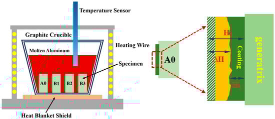
Figure 1.
Aluminum liquid corrosion experimental instrument.
Definition and uncertainty of ΔH. The corrosion thickness was measured from cross-sections using ImageJ after pixel-to-length calibration with a stage micrometer. For each specimen, multiple positions spanning the clad thickness were evaluated, and results are reported as mean ± standard deviation (SD) across positions and replicates. The ΔH plot shows error bars = ±1 SD; the replicate count (n) is indicated in the caption.
- —mean microhardness at the test condition/strain ; identical to . Unit: HV.
- —arithmetic mean hardness calculated by Equation (1).
- i—the -th hardness reading (indent ) acquired under the same condition . Unit: HV.
- i = 1—index of measurements within the set.
- n + 1—total number of measurements used to compute in Equation (1).
- ε—the test condition or strain level corresponding to the set of readings (e.g., before/after exposure, or strain level 1/2).
- ε1,ε2—the two conditions/strain levels compared in Equation (2).
- —difference in mean hardness between the two conditions, as defined by Equation (2). Unit: HV.
Composition selection and rationale. As summarized in Table 2, the TiB2–TiC fraction was set to 5, 10, and 20 wt.% to cover (i) a low-loading condition that preserves wetting, melt-pool fluidity, and a continuous Fe–B skeleton, (ii) an intermediate condition suitable for evaluating particle pinning and the interruption/refinement of the Fe–Al IMC layer at acceptable porosity, and (iii) an upper-bound condition within the present processing window (see Table 3 for parameters). Ceramic fractions above 20 wt.% were not tested in this study; based on widely reported processability limits for laser-clad Fe-based coatings with ceramic reinforcements, excessive ceramic tends to decrease melt flow and increase agglomeration/porosity. Accordingly, the quantitative analysis in this paper is confined to ≤20 wt.%.
3. Experimental Results
3.1. Macroscopic Morphology
Figure 2 illustrates the macroscopic morphological characteristics of the in situ synthesized TiB2-TiC composite coatings prepared via laser cladding technology. At ≤200× screening, no macroscopic lack-of-fusion or cracking was observed; however, localized micron-scale pores are occasionally discernible and are addressed qualitatively in Section 3.2 and Section 3.4. Compared to traditional metal matrix composites, the cladding layer surface quality did not degrade progressively with increasing ceramic content, and uniform weld textures were observed across all samples. However, due to the propensity of titanium to undergo thermal oxidation at elevated temperatures [22], localized darkening occurred in samples with excessive Ti-based ceramic additions (Figure 2c,d), despite high-flow argon shielding (12 L·min−1).
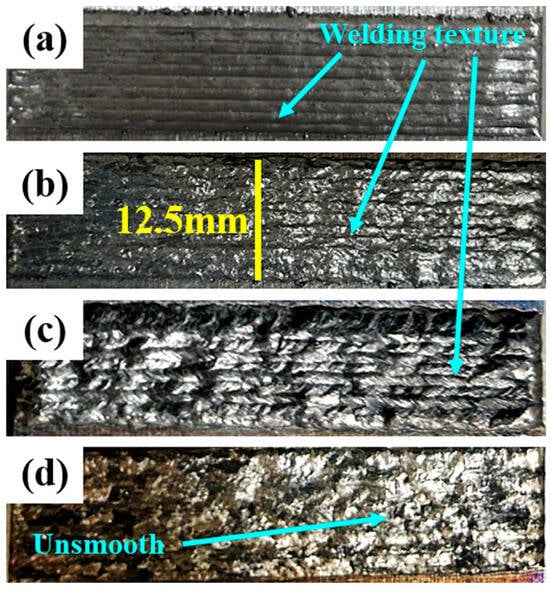
Figure 2.
Macro-morphology of cladding surfaces at different ceramic (Ti + B4C) contents: (a) 0 wt.%, (b) 5 wt.%, (c) 10 wt.%, (d) 20 wt.%. Cladding-track texture is evident on all samples; with higher ceramic content the surface becomes more irregular. All panels share the same field of view; yellow bar = 12.5 mm.
3.2. Phase Analysis
Figure 3 presents the XRD patterns of specimens with varying ceramic (Ti + B4C) contents. The XRD analysis of the A0 coating reveals that the primary phases in the conventional Fe-B-based alloy coating are α-(Fe,Cr) and M2B-type (Fe,Cr)2B. Upon introducing the in situ ceramic powder system (Ti + B4C) into the Fe-B alloy, distinct diffraction peaks corresponding to TiC and TiB2 ceramic phases emerge in the B1-B3 cladding layers, facilitated by mechanical ball-mixing and laser-induced high-temperature catalysis. Figure 3 presents the XRD patterns of specimens with varying ceramic (Ti + B4C) contents. The XRD analysis of the A0 coating reveals that the primary phases in the conventional Fe–B–based alloy coating are α-(Fe,Cr) and M2B-type (Fe,Cr)2B. Upon introducing the in situ ceramic powder system (Ti + B4C) into the Fe–B alloy, distinct diffraction peaks corresponding to TiC and TiB2 emerge in the B1–B3 cladding layers, facilitated by mechanical ball-mixing and laser-induced high-temperature processing. With increasing nominal (Ti + B4C), the relative intensities of characteristic TiB2/TiC reflections become progressively stronger (Figure 3), consistent with the in situ reaction 3Ti + B4C → 2TiB2 + TiC. An apparent slight low-angle tendency of the α-(Fe,Cr) (110) peak can be discerned; considering peak overlap and instrumental uncertainty (zero/specimen displacement), we interpret this qualitatively as being consistent with solid-solution and/or tensile residual strain, rather than reporting absolute Δ2θ values. However, characteristic peaks of unreacted B4C are also detected, indicating incomplete in situ synthesis when excessive ceramic content exceeds an optimal threshold, leading to residual B4C in the cladding layers. However, characteristic peaks of unreacted B4C are also detected, indicating incomplete in situ synthesis when excessive ceramic content exceeds the optimal threshold, leading to residual B4C impurities in the cladding layers. Accordingly, within the present processing window and among the three tested fractions (5, 10, 20 wt.%), the coating shows the best combined performance at 10 wt.% TiB2–TiC (lowest mass-loss together with the most favorable IMC morphology); we therefore regard ~10 wt.% as an indicative threshold for balancing densification and IMC suppression under the current conditions.
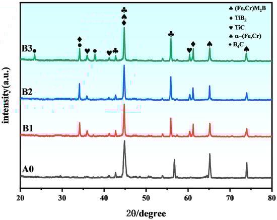
Figure 3.
XRD patterns of A0, B1, B2 and B3 with phase annotations (TiB2, TiC, α-(Fe,Cr), (Fe,Cr)MxBγ, B4C). The relative intensities of TiB2/TiC increase with the nominal (Ti + B4C) addition. A slight low-angle tendency of α-(Fe,Cr)(110) is qualitatively noted after routine instrumental checks.
Furthermore, the eutectic network skeleton within the TiB2-TiC reinforced Fe-B composite coatings remains structurally stable, predominantly composed of Fe-rich (Fe,Cr)2B. A gradual low-angle shift in the α-(Fe,Cr) diffraction peaks suggests lattice distortion (solid solution strengthening) within the cladding layers. Considering the atomic radii of Fe (1.24 Å), Ti (1.47 Å), B (0.85 Å), and C (0.77 Å), it is hypothesized that Ti atoms predominantly occupy substitutional solid solution sites, while B and C atoms form interstitial solid solutions [23].
Based on thermodynamic data and prior studies [20], the in situ reactions can be described as follows:
3Ti + B4C = TiC + 2TiB2
Fe + Ti = FeTi
8Fe + B4C = 4Fe2B + C
4Fe + B4C = 4FeB + C
2Fe + Ti = Fe2Ti
2FeB + Ti = 2Fe + TiB2
3Fe2Ti + B4C = 6Fe + 2TiB2 + TiC
3FeTi + B4C = 3Fe + 2TiB2 + TiC
2Fe2B + Ti = 4Fe + TiB2
The thermodynamic software HSC 6.0 was employed to calculate the temperature-shown in Figure 4, the Gibbs free energy values for all reactions in the system are negative, confirming their thermodynamic spontaneity. Notably, the target reaction exhibits the lowest ΔG and ΔH values, indicating not only a stronger driving force for spontaneous progression but also the formation of the most thermodynamically stable products within the system. Consequently, TiB2 and Al2O3 are identified as the dominant equilibrium phases, demonstrating preferential formation under the given conditions.
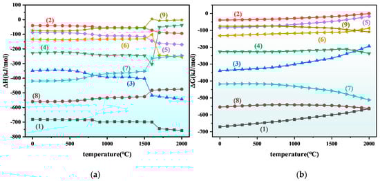
Figure 4.
Thermodynamic curves of Ti + B4C system at different temperatures: (a) enthalpy change (b) Gibbs free energy. (1) 3Ti + B4C = TiC + 2TiB2 (2) Fe + Ti = FeTi (3) 8Fe + B4C = 4Fe2B + C (4) 4Fe + B4C = 4FeB + C (5) 2Fe + Ti = Fe2Ti (6) 2FeB + Ti = 2Fe + TiB2 (7) 3Fe2Ti + B4C = 6Fe + 2TiB2 + TiC (8) 3FeTi + B4C = 3Fe + 2TiB2 + TiC (9) 2Fe2B + Ti = 4Fe + TiB2.
Qualitative interface evidence and limitation. In high-magnification BSE/SE images, particles attributed to former B4C typically show a bright reaction rim at the ceramic/matrix boundary, which is consistent with the in situ formation of TiB2 and TiC, in agreement with the XRD phase identification. At high ceramic loading, some particles retain a residual B4C core with an incomplete rim, indicating partial conversion. Because element-mapping (EDS/EPMA) and TEM were not acquired for this dataset, particle-scale phase assignment remains qualitative, and we refrain from definitive compositional claims.
3.3. Microstructure Analysis of Cladding Layer
Figure 5 displays cross-sectional microstructures of specimens from different experimental groups. A dendrite-free zone is observed at the coating-substrate interface, indicating uniform atomic arrangement and robust metallurgical bonding. This confirms the feasibility of the in situ synthesis system and provides a foundation for subsequent performance evaluations [24].
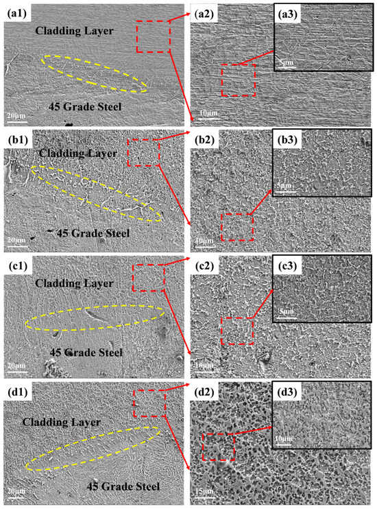
Figure 5.
Cross-sectional SEM micrographs of cladding layers at different ceramic (Ti + B4C) contents: (a) 5 wt.%, (b) 10 wt.%, (c) 20 wt.%. Left: low-magnification overview showing the AISI 1045 steel substrate and the cladding layer; middle/right: higher magnifications of the cladding microstructure. Arrows indicate representative pores; porosity is qualitatively assessed from cross-sections (no micro-CT available). Scale bars: left panels 20 µm; middle panels 10/15 µm as labeled; insets 5/10 µm. High-magnification subpanels of (d): (d1) top zone, (d2) mid-thickness, (d3) coating/substrate interface, highlighting particle clustering, pores/microcracks, and interfacial IMC (where present). Scale bars as indicated.
As defined in Figure 5, panels (a–c) correspond to 5/10/20 wt.% overviews, while (d, d1–d3) present the 20 wt.% sample at increasing magnifications (top/middle/interface) to resolve local defects and IMC features.
As shown in Figure 5(a1–a3), the coating exhibits a dense and homogeneous structure without pores or cracks. However, discontinuous or fragile eutectic structures appear as lamellar features. With 5 wt.% ceramic additions (TiB2-TiC), the originally uniform eutectic network in the Fe-B matrix becomes fragmented and disordered. This disruption likely arises from localized chemical imbalances caused by ceramic phase incorporation, which destabilizes eutectic formation. Furthermore, the co-precipitation of TiB2 and TiC (synthesized under similar temperature conditions) promotes particle aggregation during solidification, further compromising structural homogeneity [25].
Figure 5(b1–b3) illustrate the microstructure of the B2 specimen (10 wt.% ceramic). Compared to B1, the B2 sample demonstrates a more continuous and uniform eutectic network. This improvement is attributed to two factors: (1) optimal TiC/TiB2 content provides abundant nucleation sites, lowering nucleation barriers; (2) increased interparticle interactions reduce agglomeration, enabling stable ceramic dispersion and mitigating suppression of eutectic growth.
At 20 wt.% ceramic content (Figure 5(c1–c3)), severe particle agglomeration disrupts the eutectic network. Phase analysis (Figure 5(c2)) confirms residual B4C, indicating incomplete in situ reactions. The cladding process is hypothesized as follows: Initially, Ti powder envelops B4C particles, initiating in situ synthesis. As the molten pool cools, high-melting-point phases (TiB2, TiC, unreacted B4C) precipitate first. Subsequent Ti consumption of residual B4C generates finer TiB2/TiC particles, which diffuse outward. However, excessive ceramic content drives preferential attachment of TiB2/TiC to unreacted B4C, forming large ceramic aggregates. Concurrently, competitive B-atom consumption between Ti and (Fe,Cr)M2B phases destabilizes M2B eutectic formation, resulting in chaotic microstructures that degrade material performance [26].
During coating fabrication, density differences between in situ synthesized TiB2 (4.50 g/cm3), TiC (4.93 g/cm3), and the Fe-B matrix (7.85 g/cm3) induce upward ceramic migration in the molten pool. Consequently, the upper cladding layer exhibits significantly higher ceramic concentration than the lower regions. To analyze this heterogeneity, backscattered electron imaging and elemental mapping were selectively performed on the upper layers [27].
Figure 6 displays the backscattered electron scanning electron microscopy (BSE-SEM) images and elemental mapping analysis of Fe-B-based composite cladding layers with varying ceramic (TiB2-TiC) contents. As shown in Figure 6(a1,a2), the B1 specimen (5 wt.% ceramic) exhibits incomplete and fragmented network-like eutectic structures. Cr enrichment remains evident in these regions, which, combined with XRD phase analysis (Figure 3), suggests a stacking configuration dominated by (Fe,Cr)M2B and α-Fe. Furthermore, Ti segregation is observed, with localized aggregation likely corresponding to TiB2-TiC ceramic clusters. This phenomenon disrupts the equilibrium and continuity of the eutectic reaction, leading to a structural transition from interconnected eutectic networks to partially isolated lamellar eutectic phases.
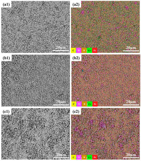
Figure 6.
Different ceramic content (TiB2-TiC) boron-iron-based composite coating microstructure backscattered scanning electron microscopy and elemental analysis layered image: (a1) 5wt.%; (a2) 5 wt.% mapping; (b1) 10 wt.%; (b2) 10 wt.% mapping; (c1) 20 wt.%; (c2) 20 wt.% mapping.
For the composite cladding with 10 wt.% ceramic (TiB2-TiC) in Figure 6(b1,b2), a relatively complete network-like eutectic skeleton is observed. Compositional analysis (Figure 7) reveals that the eutectic framework of the B2 specimen is densely populated with blocky TiB2 and petal-shaped TiC phases. The distinct growth morphologies of TiB2 and TiC originate from their divergent crystal structures. TiB2 adopts an A1B2-type hexagonal crystal system, where its high Jackson factor (5.3) promotes atomically smooth solid–liquid interfaces during solidification, favoring a two-dimensional nucleation growth mechanism. Ti and B atoms alternately accumulate along the densely packed {0001} planes and sub-packed {1010} planes, ultimately forming flattened hexagonal platelets that predominantly manifest as rectangular or polygonal particles under molten pool flow effects [28]. In contrast, TiC exhibits a NaCl-type cubic structure with isotropic growth characteristics. The centrosymmetric distribution of C atoms at octahedral interstitial sites eliminates growth anisotropy, resulting in equiaxed grains that evolve into symmetric flower-like particles in the cladding layer [29].
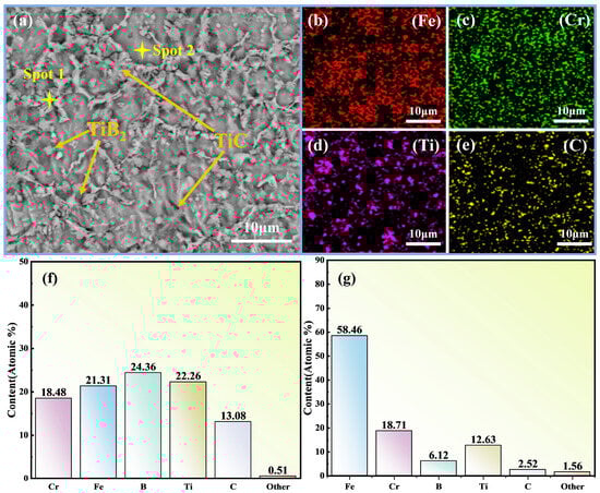
Figure 7.
Element distribution in the cladding layer of B2 sample. (a) SEM micrograph of the cladding layer with analysis positions (Spot 1 and Spot 2) and typical phases (TiB2, TiC) indicated; (b) EDS elemental map of Fe; (c) EDS elemental map of Cr; (d) EDS elemental map of Ti; (e) EDS elemental map of C; (f) EDS quantitative composition at Spot 1 (atomic %); (g) EDS quantitative composition at Spot 2 (atomic %).
Based on XRD (Section 3.1), the matrix is α-(Fe,Cr) and the eutectic network consists of Fe-rich (Fe,Cr)M2B together with TiB2/TiC. The EDS maps in Figure 7b–e show elemental distributions only and indicate a comparatively homogeneous spatial distribution of Fe, Cr, Ti and C; they do not directly identify phases. The micrographs in Figure 7a,f,g further suggest that TiB2 participates in the eutectic and TiC tends to nucleate synergistically on TiB2 surfaces. With a reduced B level, its affinity for Cr is diminished, thereby mitigating Cr segregation within the eutectic.
When the ceramic content increases to 20 wt.%, large-scale ceramic aggregates form in the cladding layer. In situ, massive agglomerates form through epitaxial growth. This results in structural instability, stress concentration, and deteriorated mechanical properties. Additionally, as previously analyzed, reduced B content suppresses Cr enrichment trends.
Figure 8 illustrates the microstructural evolution of Fe-B-based composite coatings reinforced with varying ceramic (TiB2-TiC) contents. At the initial stage of the experiment, the Fe-B alloy, Ti powder, and B4C particles were melted under the thermal effect of a high-energy laser beam, inducing elemental diffusion within the molten pool. As the temperature gradually decreased, solidification commenced. Based on Gibbs free energy calculations, TiB2-TiC phases preferentially nucleated and precipitated during cooling.
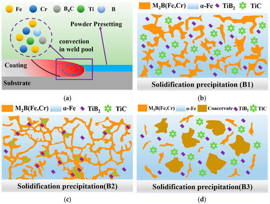
Figure 8.
Micro-forming schematic diagram of ceramic composite coatings with different contents. (a) Powder presetting on the substrate/coating and convection in the weld pool; (b) Solidification precipitation B1: dispersed M2B(Fe,Cr) in an α-Fe matrix with TiB2 and TiC particles; (c) Solidification precipitation B2: network-like M2B(Fe,Cr) together with α-Fe, TiB2, and TiC; (d) Solidification precipitation B3: coarsened α-Fe with M2B(Fe,Cr), coacervate regions, and dispersed TiB2/TiC.
At a low ceramic content (5 wt.%), the ceramic phases caused localized chemical composition imbalance, compromising the stability of the eutectic structure and resulting in fragmented and disordered eutectic formations. When the ceramic content increased to 10 wt.%, the ceramic system provided a stable B source, enabling the co-growth and mutual anchoring of TiB2-TiC and M2B(Fe,Cr) phases. This synergistic interaction facilitated the formation of a uniform, dense, and stable ceramic-reinforced eutectic network skeleton.
For the B3 specimen with excessive ceramic content (20 wt.%), the mobility of ceramic phases within the molten pool was restricted, leading to incomplete in situ synthesis reactions. Following laser irradiation, rapid cooling of the molten pool triggered the preferential precipitation of incompletely reacted B4C particles (highest melting point: 2350 °C). Newly formed TiB2-TiC phases subsequently nucleated and grew epitaxially on these B4C particles, ultimately forming heterogeneous ceramic agglomerates unevenly distributed in the middle-upper regions of the cladding layer. Concurrently, insufficient reaction kinetics and reduced B availability intensified Ti-induced B depletion from the Fe-B matrix, significantly inhibiting the development of eutectic boride frameworks. This resulted in coarse ceramic aggregates and sparse, short lamellar eutectic structures within the coating.
3.4. Corrosion Performance Analysis of Molten Aluminum
Figure 9 presents the microstructural morphology of specimens after 60 h of corrosion in molten aluminum. As shown in Figure 9(a0,a1), when conventional Fe-B alloy contacts molten aluminum, element exchange occurs at the interface, forming a compound layer dominated by FexAly (Fe2Al5, FeAl3), which inhibits further penetration and erosion by the aluminum melt. The eutectic structure within the coating provides structural support and anchoring. However, weak zones exist between interconnected lamellar structures, leading to brittle fracture. Additionally, the compound layer near the coating region is primarily composed of Fe2Al5, which exhibits weak interfacial bonding and is prone to spalling. These factors result in molten aluminum penetrating the compound layer after 60 h of corrosion, forming secondary corrosion fronts with crack clusters at the coating interface, thereby accelerating service failure [30,31].
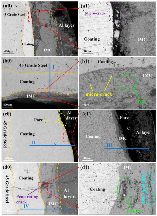
Figure 9.
Micromorphology of molten aluminum after corrosion for 60 h: (a0) B1 coating; (a1) Local enlarged image; (b0) B3 coating; (b1) Local enlarged image; (c0) B2 coating; (c1) Local enlarged image. (d0,d1) further reveal extensive defects at the corrosion interface, including through-thickness cracks, spalling cracks, and corrosion pits.
In Figure 9(b0), the B3 specimen exhibits a conventional three-layer corrosion structure: steel substrate (45# steel), composite cladding layer, and FexAly intermetallic compound (IMC) layer. Elemental line scanning analysis (Line Scan I in Figure 10) reveals a stepwise increase in Al content and a gradual decrease in Fe content across the layers, with trace amounts of Ti and Cr detected in the IMC region. This indicates that the eutectic structure and TiB2-TiC phases play critical roles in corrosion resistance: These interfacial features—non-conformal contact and local dewetting gaps in Figure 9, together with the sharp drop of Al on the coating side in the line scan of Figure 10—are consistent with limited wetting/spreading of molten Al on the eutectic and TiB2–TiC surfaces under the present conditions. In addition, the TiB2–TiC particles help stabilize the corrosion layer and improve adhesion at the substrate/IMC interface, reducing spalling and dissolution of corrosion products [18]. In this work, the corrosion layer refers to the reaction-affected zone that forms at the coating/molten-Al interface during immersion. It typically consists of compact Fe–Al intermetallics (reaction layer, adherent to the coating) and may include a thin outer band of corrosion products. We report the layer thickness as the average distance from the original coating surface to the outer boundary of the continuous reaction zone, measured on polished cross-sections. A thinner, more uniform layer generally indicates better resistance because it reflects slower interdiffusion and fewer fast pathways for Al ingress. When the Fe-based matrix contacts molten Al, interdiffusion produces Fe–Al intermetallic compounds (IMCs) that grow with time and temperature (often showing a tongue-like morphology. The ceramic reinforcements act differently: TiB2 is chemically stable and creates rigid, non-reactive barriers that block interdiffusion pathways; TiC is comparatively less inert and benefits from being embedded in a boron-rich matrix, which helps interrupt IMC continuity and limits through-thickness penetration. Overall, a higher fraction and better dispersion of hard ceramics reduce the effective diffusion area, suppress IMC coarsening, and thus retard corrosion-layer growth. Corrosion products are the reaction products formed at the coating/molten-Al interface during immersion. In our system the dominant products are Fe–Al intermetallic compounds (IMCs)—mainly Fe2Al5 and FeAl3—generated by mutual diffusion of Fe and Al. A thin Al-rich solidified layer may locally adhere on top of the IMC, and minor surface oxides can appear at open regions; unless stated otherwise, our thickness values refer to the IMC layer only. The ceramic reinforcements (TiB2/TiC) are essentially inert under the present conditions and remain as discrete particles rather than dissolving into the corrosion products. XRD is used for phase identification (Figure 6), whereas EDS/line scans (Figure 10) show elemental distributions consistent with these products. Functionally, the IMC layer can initially impede penetration of molten Al (Figure 9), but when it becomes cracked or porous it provides paths for Al ingress and accelerates failure.
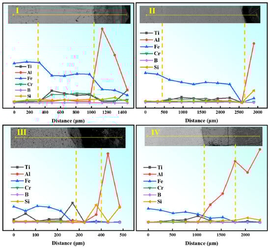
Figure 10.
EDS line scan results of microstructure after 60 h of aluminum liquid corrosion. (I): Line-scan collected along path I indicated in the inset, traversing from the coating surface across the coating/transition layer to the substrate; (II): Line-scan along path II (longer traverse) from surface → coating → transition layer → substrate; (III): Line-scan along path III within a representative region of the coating and across the coating/transition interface; (IV): Line-scan along path IV from the coating towards the substrate across the coating/transition interface. Notes: Yellow dashed vertical lines mark the boundaries between surface/coating/transition layer/substrate; distance (µm) is measured along each path from the left endpoint shown in the inset; the element-color legend applies to all panels.
A magnified view (Figure 9(b1)) reveals the presence of a planar liquid-solid (PLS) interface in the IMC layer, which significantly inhibits interdiffusion between the substrate and molten aluminum while improving interfacial adhesion [15]. However, numerous microcracks within the IMC layer facilitate molten aluminum penetration into the cladding layer.
For the B2(c0) specimen with 10 wt.% ceramic content, a four-layer microstructure is observed: metal substrate (45# steel), composite cladding layer, IMC layer, and solidified Al layer. Unlike other specimens, the Al and IMC layers are incompletely bonded, with large interfacial pores. This is likely attributed to spalling-type cracks in the IMC layer, causing detachment during post-corrosion sample preparation. Elemental mapping (Line Scans II and III in Figure 10) confirms consistent elemental distributions. Figure 9(d0,d1) further reveal extensive defects at the corrosion interface, including through-thickness cracks, spalling cracks, and corrosion pits. The corrosion interface is the reaction front formed during immersion where the coating contacts molten Al—i.e., the boundary between the coating side (cladding/steel) and the corrosion products (Fe–Al IMC layer, mainly Fe2Al5/FeAl3), and on the Al side the IMC/Al contact line. This is the locus of Fe ↔ Al interdiffusion and IMC nucleation/growth. When we refer to “defects at the corrosion interface,” we mean interfacial gaps/dewetting voids, microcracks, or local spalling along this boundary (see Figure 9). Phase identification follows XRD; EDS shows elemental distributions only. Molten aluminum infiltrates the coating through these microcracks, forming erosion channels and corrosion pits. Additionally, spalling cracks promote rapid dissolution of the IMC layer in molten aluminum, leading to complete coating failure (complete coating failure means that the coating no longer provides a continuous barrier against molten Al—i.e., the IMC/cladding becomes discontinuous due to spalling and through-thickness cracks, creating percolating channels that allow molten Al to reach the substrate and cause large-area delamination/dissolution; see Figure 9(d0,d1) for a representative morphology). Comparative analysis demonstrates that the B2 specimen exhibits the highest corrosion resistance among the three groups. Qualitatively, specimens exhibiting more apparent pores prior to exposure tended to show larger thickness loss ΔH after molten-Al attack; we refrain from claiming a quantitative correlation in the absence of volumetric porosity data.
A limitation of this study is the lack of volumetric porosity data; future work will quantify porosity (area/volume fraction and size distribution) using micro-CT and ASTM-style image analysis to enable statistical correlations with ΔH.
Overall, microcracks are observed in the IMC layers of all specimens. This is attributed to the Fe-rich (Fe,Cr)M2B phase in the eutectic structure, which adopts a body-centered tetragonal (BCT) lattice similar to Fe2B. The inherent corrosion heterogeneity and structural asymmetry of this phase reflect the intrinsic limitations of conventional Fe-B alloys, where molten aluminum exploits microcracks as corrosion pathways [32]. However, the B2 specimen benefits from homogeneous Cr and Ti distribution, which facilitates uniform protective mechanisms and avoids localized corrosion weak points caused by elemental segregation [33]. The uniform dispersion of TiB2-TiC further enhances corrosion resistance by mitigating localized attack. Despite residual crack-related risks, the B2 specimen maintains superior durability in molten aluminum due to its optimized corrosion-resistant microstructure.
3.5. Corrosion Amount and Corrosion Rate Analysis
A T-L-K model has been developed by researchers to quantitatively evaluate the resistance of materials to molten aluminum corrosion [9]. However, practical operating conditions reveal that microcrack formation within coatings significantly accelerates service life degradation. To address this, the present study incorporates microcrack effects into the computational framework and optimizes the corrosion prediction formula based on experimental data. The following assumptions are proposed to define material corrosion behavior: (1) The diffusion coefficient in the intermetallic compound (IMC) layer is independent of its chemical composition. (2) Aluminum concentration within the IMC layer remains uniformly distributed, unaffected by spatial position. Parameter sourcing—All mechanical and transport parameters used in this section are literature-derived for comparable materials/temperatures and are cited at first use; they are employed without calibration to the present dataset, and no parameter was tuned to match .
According to the T-L-K model, IMC thickness evolution is governed by its growth at the C1 interface (coating/IMC boundary) and dissolution at the C2 interface (IMC/molten aluminum boundary).
- is the molar mass of the IMC layer, reported as 2.47 × 10⁻¹ kg·mol−1 [34];
- is the density of IMC layer, reported as 4.2 × 10³ kg · m3 [34];
- D is the mutual diffusion coefficient of the IMC layer, reported as 3.9 × 10⁻⁹ m2·s−1 [14];
- is the saturated concentration of iron in liquid molten aluminum, which is 1.07 × 10³ mol/m3 [35];
- is the fracture toughness of the compound layer (MPa·m1/2);
- is the crack propagation inhibition coefficient of the compound layer (IMC);
- is the crack correction factor;
- and are the aluminum concentration (mol/m3) at interface 1 and interface
- is the corrosion inhibition factor;
- KIC(T0) is the fracture toughness at the reference temperature (20 °C), with a value of 9.74 MPa·m1/2 [36];
- α is the sensitivity coefficient of temperature to fracture toughness;
- T is the actual operating temperature (750 °C);
- is the strain rate of compound layer (IMC);
- d is the grain size in IMC, d0 reference grain size (Å);
- γ is the sensitivity coefficient of loading rate to fracture toughness;
- δ is the phase transition coefficient;
- the overall thermal expansion coefficient of material is 10.95 × 10⁻⁶ °C [14];
- λ is the influence coefficient of thermal conductivity on fracture toughness;
- is the influence coefficient of crack length on the diffusion rate of Al element;
- is the overall fracture toughness of the cladding layer (MPa·m1/2);
- is the ratio of crack length to reference length L0, which indicates the degree of crack propagation.
- is the ratio of stress intensity factor to fracture toughness, which indicates the stress concentration effect at the crack tip.
- and are the reference temperature (°C) and the reference aluminum concentration (mol/m3), respectively. Cn and m are empirical indices;
- when , the dissolution and growth of IMC layer reach equilibrium, and the maximum thickness of IMC layer (μm) can be obtained.
Parametric sensitivity (qualitative). Within the present frame work, the corrosion thickness follows . Increasing the effective transport (e.g., larger interdiffusion or higher interfacial driving ) increases , whereas higher fracture toughness reduces crack-assisted spalling according to the energy criterion . The inhibition factor and the crack-correction factor shift the predicted curves monotonically in the expected directions. These results are non-calibrated scenario/sensitivity envelopes; no parameter was tuned to match .
By incorporating the experimental data from the specimens in this chapter, the computational results are summarized in Figure 11. After introducing TiB2-TiC ceramic phases into the Fe-B-based alloy, the fracture toughness (KIC0, KIB1) of the cladding layer and intermetallic compound (IMC) layer at high temperatures (760 °C) shows limited improvement compared to the A0 specimen. Notably, the B3 specimen exhibits even lower fracture toughness than A0, consistent with the corrosion morphology observations where IMC layers in all specimens develop microcracks of varying sizes. These microcracks facilitate the formation of through-thickness corrosion channels for molten aluminum penetration. Figure 11b displays the stabilized IMC layer thickness after corrosion, with the B2 specimen demonstrating the thinnest IMC layer, corroborating its superior corrosion resistance. Furthermore, as shown in Figure 11c, the B2 specimen achieves the highest corrosion inhibition factor (ε) and crack correction factor (β). Nevertheless, microcracks remain a critical factor limiting the service life of this composite coating system. Finally, Figure 11d quantifies the corrosion layer thickness and corrosion rate across specimens, confirming the performance hierarchy: B2 (best) > B1 > B3 (worst).
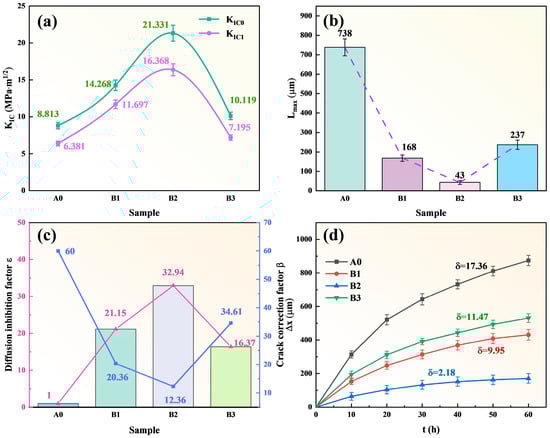
Figure 11.
Sample data of each group: (a) High temperature fracture toughness (KIC) of clad ding layer and compound layer (IMC); (b) The thickness of the compound layer after stable corrosion (Lmax); (c) Corrosion inhibition factor and crack correction factor; The magenta line shows the trend of the bar-plot quantity (left y-axis), whereas the blue line represents the crack correction factor β (right y-axis); (d) Relationship between corrosion thickness loss and corrosion time.
Scope—Model outputs are scenario/sensitivity envelopes based on literature-derived parameters rather than statistical fits; quantitative prediction for this system will require future direct measurements.
3.6. Corrosion Mechanism
Figure 12 illustrates the failure modes and strengthening mechanisms of TiB2-TiC-reinforced Fe-B-based compo site coatings in molten aluminum. Upon exposure to molten aluminum at 760 °C, elemental interdiffusion occurs: Al and Si penetrate the composite cladding layer, while Fe and Cr dissolve into the molten aluminum, forming a transition layer (intermetallic compound, IMC). For the B1 specimen (5 wt.% ceramic), Al preferentially reacts with α-(Fe,Cr) to form an IMC layer dominated by FexAly phases (FeAl3, Fe2Al5, Fe4Al9). Due to the disordered and incomplete eutectic (Fe,Cr)M2B structure within the specimen, the overall resistance to aluminum erosion is compromise [38], leading to corrosion reactions such as (Fe,Cr)2B + Al → Cr-Al-B + Fe-Al [14]. Furthermore, the absence of a robust eutectic network in the FexAly IMC layer promotes defect formation (e.g., spalling, cracks, corrosion pits). The failure mechanism involves molten aluminum infiltrating new coating regions through cracks, accelerating degradation. However, uniformly dispersed ceramic phases in the IMC region temporarily inhibit crack propagation and aluminum penetration, constituting the primary strengthening mechanism for the B1 specimen.
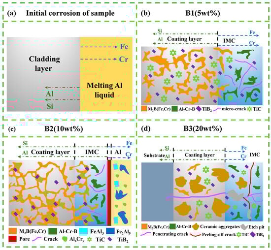
Figure 12.
Schematic illustration of the initial corrosion stage and corrosion features of coatings with different TiB2–TiC powder additions in molten Al. (a) Initial corrosion of sample: diffusion directions of Al/Si from the melt into the coating and Fe/Cr outward from the coating; (b) B1 (5 wt.%) coating: corrosion morphology showing dispersed M2B(Fe,Cr), Al–Cr–B products, TiB2/TiC particles, and micro-cracks near the IMC region; (c) B2 (10 wt.%) coating: network-like M2B(Fe,Cr) and Al–Cr–B phases with IMC growth and an Al accumulation band at the outer surface; (d) B3 (20 wt.%) coating: coarsened ceramic aggregates in the coating, with penetrating cracks and peeling-off cracks around the IMC region. The legend at the bottom applies to all panels.
For the B2 specimen (10 wt.% ceramic), the cladding layer features a more complete eutectic structure, where ceramic particles enhance the stability of the network. However, the body-centered orthorhombic (BCO) lattice of (Fe,Cr)M2B imposes inherent limitations on load-bearing capacity and fracture toughness. Under cyclic thermal stresses, microcracks develop near the IMC/Al interface, causing interfacial spalling and pore formation. Concurrently, reduced Ti and Cr segregation improves overall corrosion resistance by mitigating localized attack.
In the B3 specimen (20 wt.% ceramic), excessive ceramic aggregates and structural defects (e.g., voids) severely degrade stability. Cyclic thermal stresses from molten aluminum induce extensive spalling and through-thickness cracks, resulting in rapid coating failure [39].
In summary, crack propagation is the critical factor limiting corrosion resistance in this system. The B2 specimen demonstrates optimal performance due to its homogeneous ceramic distribution, relatively intact (Fe,Cr)M2B eutectic network, and uniformly dispersed Cr, which enhances oxidation resistance.
4. Conclusions
- Fe-B-based composite coatings with varying TiB2-TiC ceramic contents were in situ synthesized via laser cladding technology. At a ceramic content of 10 wt.%, the (Fe,Cr)M2B eutectic network structure exhibited high integrity and uniform distribution, with TiB2-TiC phases acting as reinforcing agents to enhance the load-bearing threshold and structural stability. Additionally, elemental segregation of Cr and Ti within the coating was significantly alleviated.
- During the 60 h molten aluminum corrosion test, the TiB2-TiC-reinforced Fe-B-based composite coatings exhibited pronounced microcrack formation, enabling molten aluminum to penetrate through microcracks in the IMC layer, creating through-thickness corrosion channels. The B2 specimen demonstrated optimal corrosion resistance in this system, approximately 5.3 times higher than that of conventional Fe-B-based alloys. This performance is attributed to the uniform dispersion of ceramic particles, which effectively hindered crack propagation, combined with the barrier effect of Cr-derived oxide films that retarded aluminum infiltration.
- Quantitative corrosion analysis of the TiB2-TiC-reinforced Fe-B-based composite coatings revealed that, compared to Al2O3-TiB2-reinforced Fe-B-based coatings, this system exhibited lower fracture toughness in both the composite layer and IMC layer but a higher crack correction factor (β). Overall, the B2 specimen achieved the highest corrosion inhibition factor within the system, consistent with experimental observations.
A limitation of this study is the absence of high-resolution compositional mapping (EDS/EPMA) and TEM; future work will acquire these data to quantify reaction-rim chemistry and further validate the proposed in situ pathway.
Author Contributions
Conceptualization, L.C.; methodology, L.C.; software, L.C. and S.L.; validation, L.C. and S.L.; formal analysis, L.C.; investigation, L.C.; resources, J.Y.; data curation, S.L.; writing—original draft preparation, L.C.; writing—review and editing, J.Y. and S.L.; visualization, L.C.; supervision, J.Y.; project administration, J.Y.; funding acquisition, J.Y. All authors have read and agreed to the published version of the manuscript.
Funding
This research received no external funding.
Institutional Review Board Statement
Not applicable.
Informed Consent Statement
Not applicable.
Data Availability Statement
The data supporting the findings of this study are openly available in the article. The data presented in this study are available on request from the corresponding author. The data are not publicly available due to institutional policy restrictions.
Acknowledgments
The authors would like to thank the laboratory technicians and research assistants for their support in the experimental setup and data collection. The authors also acknowledge the administrative and technical assistance provided by the School of Shandong University of Science and Technology.
Conflicts of Interest
The authors declare no conflicts of interest.
Abbreviations
The following abbreviations are used in this manuscript:
| MDPI | Multidisciplinary Digital Publishing Institute |
| 3D | Three-Dimensional |
| wt.% | Weight Percent |
| Fe-B | Iron–Boron |
| TiB2 | Titanium Diboride |
| TiC | Titanium Carbide |
| B4C | Boron Carbide |
| IMC | Intermetallic Compound |
| FexAly | Iron–Aluminum Intermetallic Compounds |
| SEM | Scanning Electron Microscopy |
| BSE | Backscattered Electron |
| SE | Secondary Electron |
| EDS | Energy-Dispersive X-ray Spectroscopy |
| XRD | X-ray Diffraction |
| SPS | Spark Plasma Sintering |
| AISI | American Iron and Steel Institute |
References
- Labe, D.; Pongratz, D.; Hugoviczl, P. Manufacturing sustainable aluminum from recycled scrap: The science of “dirty” alloys. Prog. Mater. Sci. 2022, 128, 100947. [Google Scholar]
- Zhao, L.; Song, L.; Macías, J.G.S. Correlation between microstructure and mechanical properties of AlSi10Mg fabricated by laser powder bed fusion: A review. Addit. Manuf. 2022, 56, 102914. [Google Scholar]
- Wang, M.; Xue, J.; Gao, R. Interfacial morphology and corrosion behavior of bulk Fe2B in liquid aluminum. Mater. Charact. 2019, 152, 1–11. [Google Scholar] [CrossRef]
- Zhang, X.; Chen, W. Review of corrosion and wear resistance of cast metals in molten aluminum and its alloys. J. Chin. Soc. Nonferrous Met. 2015, 25, 1715–1731. (In Chinese) [Google Scholar] [CrossRef]
- Stemper, L.; Tunes, M.A.; Tosone, R. On the potential of red-dot aluminum alloys. Prog. Mater. Sci. 2022, 124, 100873. [Google Scholar] [CrossRef]
- Xu, G.; Wang, K.; Dong, X. Review on corrosion resistance of mild steels in liquid aluminum. J. Mater. Sci. Technol. 2021, 71, 12–22. [Google Scholar] [CrossRef]
- Jurči, P.; Dlouhý, I. Cryogenic treatment of martensitic steels: Microstructural basis and its effect on mechanical properties, wear and corrosion performance. Materials 2024, 17, 548. [Google Scholar] [CrossRef]
- Aribo, S.; Fakorede, A.; Ige, O. Erosion–corrosion behaviour of hybrid 6063 aluminium alloy composites. Wear 2017, 376–377, 608–614. [Google Scholar] [CrossRef]
- Xu, G.; Wang, K.; Dong, X. Experimental and theoretical study on corrosion resistance of iron alloys in aluminum melts. Metall. Mater. Trans. A 2019, 50, 4665–4676. [Google Scholar] [CrossRef]
- Long, J.; Ding, W.; Yang, Y. Corrosion resistance and mechanism of Fe–Cr–Si alloys in molten aluminum. Corros. Sci. 2022, 201, 110303. [Google Scholar] [CrossRef]
- Wang, Y.J.; Fu, H. Interfacial morphology and corrosion–wear behavior of cast Fe–3.5 wt.%B steel in liquid zinc. Corros. Sci. 2018, 131, 290–299. [Google Scholar] [CrossRef]
- Zhang, X.; Chen, W.; Luo, H. Corrosion resistance and interfacial morphology of novel Fe–Cr–Mo–B alloy cast steel in molten aluminum. Corros. Sci. 2017, 125, 20–28. [Google Scholar] [CrossRef]
- Ling, Z.; Chen, W.; Lu, T. Interfacial morphology and tribo-corrosion behavior of Fe–15.3 wt.%Cr–3.1 wt.%B–6.2 wt.%Mo alloy in molten aluminum. Wear 2019, 430–431, 81–93. [Google Scholar] [CrossRef]
- Xu, G.; Wang, K.; Dong, X. Multi-scale corrosion resistance mechanism of novel Fe alloys in dynamic aluminum melts. Corros. Sci. 2020, 163, 108276. [Google Scholar] [CrossRef]
- Ma, S.; Xing, J.; Liu, G. Effect of chromium concentration on microstructure and properties of Fe–3.5B alloys. Mater. Sci. Eng. A 2010, 527, 6800–6808. [Google Scholar] [CrossRef]
- Yang, Y.; Yin, B.; Shang, Y. Preparation and characterization of novel TiB2–12(Fe–Co–Cr–Ni) cermets and their corrosion resistance in molten aluminum. Corros. Sci. 2021, 190, 109643. [Google Scholar] [CrossRef]
- Pan, C.; Gong, M.; Feng, S. Induction-clad Ni-coated TiC particle-reinforced Ni60 coating in molten aluminum alloy. Surf. Coat. Technol. 2021, 419, 127278. [Google Scholar] [CrossRef]
- Ali, A.; Ahmad, S.N. Mechanical and tribological properties of TiB2/Al2O3 coatings prepared on high-speed steel by electron beam deposition. Tribol. Int. 2022, 174, 107681. [Google Scholar] [CrossRef]
- Fang, Y.; Zhao, X.; Wu, T. Hot-pressing sintering and characterization of ultrafine-grained high-strength TiB2–TiN–Al0.3CoCrFeNi cermet materials synthesized by in situ reaction. Ceram. Int. 2024, 50, 20504–20514. [Google Scholar] [CrossRef]
- Zheng, Y.; Lian, G.; Lu, H. Defects, microstructure and properties of in situ synthesized TiB2–TiC–Bi ceramic phases by laser cladding. Ceram. Int. 2024, 50, 41097–41116. [Google Scholar] [CrossRef]
- Yuan, J.; Li, X.; Pan, G. Effect of SiO2–Si3N4 ceramic reinforcements on microstructure and molten aluminum corrosion resistance of laser-cladded Co-based coatings. Ceram. Int. 2025, 51, 13493–13506. [Google Scholar] [CrossRef]
- Chen, L.; Yu, T.; Guan, C. Microstructure and properties of Fe-based coatings reinforced with TiC and TiB2 by laser cladding. Ceram. Int. 2022, 48, 14127–14140. [Google Scholar] [CrossRef]
- Zhuang, D.D.; Tao, W.W.; Ni, H.M. Distribution and properties of TiC in TiC–CrMnFeCoNi coatings fabricated by laser cladding combined with ultrasonic treatment. Surf. Coat. Technol. 2023, 468, 129744. [Google Scholar] [CrossRef]
- Wang, Y.; Xu, L.; Zhao, L. Tribo-corrosion behavior of Fe–Cr–B alloy coatings fabricated by high-deposition-rate and conventional laser-directed energy deposition. Tribol. Int. 2024, 192, 109245. [Google Scholar] [CrossRef]
- Dong, B.X.; Li, Q.Y.; Shu, S.L. Size-tunable in situ TiB2–TiC particle-reinforced Al–Cu–Mg composites: High-temperature tribological behavior and mechanism. Tribol. Int. 2023, 177, 107943. [Google Scholar] [CrossRef]
- Zheng, Y.; Wang, Y.; Li, B. Achieving strength–ductility synergy in Al–5Cu alloy by in situ synthesized dual-phase TiB2–TiC particles. J. Alloys Compd. 2025, 1022, 179772. [Google Scholar] [CrossRef]
- Qi, X.; Li, Y.; Cui, W. Improving wear and corrosion resistance of laser-cladded Ni-based composite coatings by tailoring in situ TiB2–TiC. Ceram. Int. 2025, 51, 9442–9454. [Google Scholar] [CrossRef]
- Soleimani, F.; Adeli, M.; Soltanieh, M. Preparation and wear behavior of TiC/TiB2 reinforced Ni–Al intermetallic composites. J. Mater. Res. Technol. 2024, 30, 5770–5784. [Google Scholar] [CrossRef]
- Yang, S.; Cui, C.; Cui, S. Refinement and strengthening of Ti–46Al–4Nb alloy by in situ TiC nanoparticles and TiB2 whiskers. J. Alloys Compd. 2022, 892, 162195. [Google Scholar] [CrossRef]
- Yang, J.; Oliveira, J.P.; Li, Y. Laser technologies for dissimilar joining of aluminum alloys to steels: A critical review. J. Mater. Process. Technol. 2022, 301, 117443. [Google Scholar] [CrossRef]
- Yang, Y.; Luo, Z.; Zhang, Y. Dissimilar joining of aluminum and steels: A review. J. Manuf. Process. 2024, 110, 376–397. [Google Scholar] [CrossRef]
- Li, X.; Feng, Y.; Liu, B. Effect of NbC particles on microstructure and mechanical properties of laser-cladded AlCoCrFeNi high-entropy alloy coatings. J. Alloys Compd. 2019, 788, 485–494. [Google Scholar] [CrossRef]
- Zhang, J.; Gao, Y.; Xing, J. Effect of chromium addition on microstructure and wear resistance of Fe–B cast alloys. Tribol. Lett. 2011, 44, 31–39. [Google Scholar] [CrossRef]
- Sun, D.; Zhu, L.; Cai, Y. Tribological comparison of laser-cladded CrMnFeCoNi coatings reinforced by three types of ceramics. Surf. Coat. Technol. 2022, 450, 129013. [Google Scholar] [CrossRef]
- Cong, D.; Zhou, H.; Ren, Z. Improvement of thermal fatigue resistance of hot-work die steel by local laser surface remelting and alloying. Opt. Laser Technol. 2014, 54, 55–61. [Google Scholar] [CrossRef]
- Zhen, Y.; Xu, G.; Han, F. Enhancement of thermal fatigue resistance of Fe–Cr–B alloys by in situ particle induction. Mater. Lett. 2024, 377, 137380. [Google Scholar] [CrossRef]
- Xu, G.; Wang, K.; Zhen, Y. Application of Fe–Cr–B-based composites with multi-scale corrosion-resistant phases in high-temperature liquid aluminum. J. Mater. Res. Technol. 2024, 30, 6897–6909. [Google Scholar] [CrossRef]
- Zhou, J.; Cheng, Y.; He, B. Properties of multi-scale TiC ceramic particles reinforced high-entropy alloy coatings prepared by high-speed laser cladding: Microstructure, wear and corrosion. Appl. Surf. Sci. 2025, 685, 162061. [Google Scholar] [CrossRef]
- Ling, Z.; Fu, Z.; Yang, X. A novel Fe–Cr–Mo–B–Al steel with excellent tribo-corrosion resistance in liquid aluminum. Corros. Sci. 2022, 206, 110484. [Google Scholar] [CrossRef]
Disclaimer/Publisher’s Note: The statements, opinions and data contained in all publications are solely those of the individual author(s) and contributor(s) and not of MDPI and/or the editor(s). MDPI and/or the editor(s) disclaim responsibility for any injury to people or property resulting from any ideas, methods, instructions or products referred to in the content. |
© 2026 by the authors. Licensee MDPI, Basel, Switzerland. This article is an open access article distributed under the terms and conditions of the Creative Commons Attribution (CC BY) license.