Fabrication and Characteristics of Porous Hydroxyapatite-CaO Composite Nanofibers for Biomedical Applications


Abstract
:1. Introduction
2. Materials and Methods
2.1. Synthesis and Characterization of Porous Hydroxyapatite Nanofibers
2.2. Characterization of the p-HApF
2.3. In Vitro Study of Drug Loading and Release
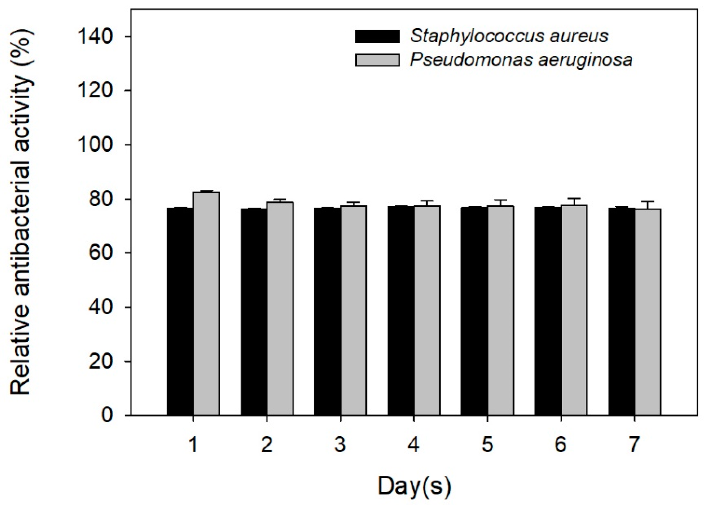
2.4. Antibiotic Activity against Staphylococcus aureus and Pseudomonas aeruginosa
3. Results and Discussions
4. Conclusions
Author Contributions
Funding
Conflicts of Interest
References
- Ben-Arfa, B.A.; Salvado, I.M.; Ferreira, J.M.; Pullar, R.C. Novel route for rapid sol-gel synthesis of hydroxyapatite, avoiding ageing and using fast drying with a 50-fold to 200-fold reduction in process time. Mater. Sci. Eng. C Mater. Biol. Appl. 2017, 70, 796–804. [Google Scholar] [CrossRef] [PubMed]
- Cüneyt Taş, A.; Korkusuz, F.; Timuçin, M.; Akkaş, N. An investigation of the chemical synthesis and high-temperature sintering behaviour of calcium hydroxyapatite (HA) and tricalcium phosphate (TCP) bioceramics. J. Mater. Sci. Mater. Med. 1997, 8, 91–96. [Google Scholar] [CrossRef] [PubMed]
- Rao, R.R.; Roopa, H.N.; Kannan, T.S. Solid state synthesis and thermal stability of HAP and HAP—beta-TCP composite ceramic powders. J. Mater. Sci. Mater. Med. 1997, 8, 511–518. [Google Scholar] [CrossRef] [PubMed]
- Li, H.; Zhang, N.; Wang, X.; Geng, X.; Yang, X.; Wang, H.; Li, B.; Liang, C. Synthesis and cytotoxicity of carbon nanotube/hydroxyapatite in situ composite powders prepared by chemical vapour deposition. Mater. Res. Innov. 2014, 18, 338–343. [Google Scholar] [CrossRef]
- Ramanan, S.R.; Venkatesh, R. A study of hydroxyapatite fibers prepared via sol-gel route. Mater. Lett. 2004, 58, 3320–3323. [Google Scholar] [CrossRef]
- Franco, P.Q.; João, C.F.C.; Silva, J.C.; Borges, J.P. Electrospun hydroxyapatite fibers from a simple sol–gel system. Mater. Lett. 2012, 67, 233–236. [Google Scholar] [CrossRef]
- Pasuri, J.; Holopainen, J.; Kokkonen, H.; Persson, M.; Kauppinen, K.; Lehenkari, P.; Santala, E.; Ritala, M.; Tuukkanen, J. Osteoclasts in the interface with electrospun hydroxyapatite. Colloids Surf. B Biointerfaces 2015, 135, 774–783. [Google Scholar] [CrossRef] [PubMed]
- Zhang, W.; Chai, Y.; Xu, X.; Wang, Y.; Cao, N. Rod-shaped hydroxyapatite with mesoporous structure as drug carriers for proteins. Appl. Surf. Sci. 2014, 322, 71–77. [Google Scholar] [CrossRef]
- Li, D.; Huang, X.; Wu, Y.; Li, J.; Cheng, W.; He, J.; Tian, H.; Huang, Y. Preparation of pH-responsive mesoporous hydroxyapatite nanoparticles for intracellular controlled release of an anticancer drug. Biomater. Sci. 2016, 4, 272–280. [Google Scholar] [CrossRef] [PubMed]
- Pistone, A.; Iannazzo, D.; Espro, C.; Galvagno, S.; Tampieri, A.; Montesi, M.; Panseri, S.; Sandri, M. Tethering of Gly-Arg-Gly-Asp-Ser-Pro-Lys Peptides on Mg-Doped Hydroxyapatite. Engineering 2017, 3, 55–59. [Google Scholar] [CrossRef]
- Gu, L.; He, X.; Wu, Z. Mesoporous hydroxyapatite: Preparation, drug adsorption, and release properties. Mater. Chem. Phys. 2014, 148, 153–158. [Google Scholar] [CrossRef]
- Cheah, W.K.; Ooi, C.W.; Othman, R.; Yeoh, F.Y. Synthesis of mesoporous hydroxyapatite through a soft template route using non-ionic surfactant. ASEAN Eng. J. Part B 2012, 1, 57–69. [Google Scholar]
- Yao, J.; Tjandra, W.; Chen, Y.Z.; Tam, K.C.; Ma, J.; Soh, B. Hydroxyapatite nanostructure material derived using cationic surfactant as a template. J. Mater. Chem. 2013, 13, 3053–3057. [Google Scholar] [CrossRef]
- Zhao, Y.F.; Ma, J.; Tan, G. Synthesis of mesoporous hydroxyapatite through neutral templating. Int. J. Nanosci. 2006, 5, 499–503. [Google Scholar] [CrossRef]
- Münchow, E.A.; Pankajakshan, D.; Albuquerque, M.T.; Kamocki, K.; Piva, E.; Gregory, R.L.; Bottino, M.C. Synthesis and characterization of CaO-loaded electrospun matrices for bone tissue engineering. Clin. Oral Investig. 2016, 20, 1921–1933. [Google Scholar] [CrossRef] [PubMed]
- Nazeer, M.A.; Yilgor, E.; Yagci, M.B.; Unal, U.; Yilgor, I. Effect of reaction solvent on hydroxyapatite synthesis in sol-gel process. R. Soc. Open Sci. 2017, 4, 171098. [Google Scholar] [CrossRef] [PubMed]
- Hatzistavrou, E.; Chatzistavrou, X.; Papadopoulou, L.; Kantiranis, N.; Chrissafis, K.; Boccaccini, A.R.; Paraskevopoulos, K.M. Sol-gel hydroxyapatite-CaO composites: Fabrication and bioactivity studies. Key Eng. Mater. 2009, 396–398, 99–102. [Google Scholar] [CrossRef]
- Baddiel, C.B.; Berry, E.E. Spectra structure correlations in hydroxy and fluorapatite. Spectrochim. Acta 1966, 22, 1407–1416. [Google Scholar] [CrossRef]
- Wang, H.; Zhang, P.; Ma, X.; Jiang, S.; Huang, Y.; Zhai, L.; Jiang, S. Preparation, characterization of electrospun meso-hydroxylapatite nanofibers and their sorptions on Co(II). J. Hazard Mater. 2014, 265, 158–165. [Google Scholar] [CrossRef] [PubMed]
- Taherian, M.; Rojaee, R.; Fathi, M.; Tamizifar, M. Effect of different sol–gel synthesis processes on microstructural and morphological characteristics of hydroxyapatite-bioactive glass composite nanopowders. J. Adv. Ceram. 2014, 3, 207–214. [Google Scholar] [CrossRef]
- Bilton, M.; Milne, S.J.; Brown, A.P. Comparison of hydrothermal and sol-gel synthesis of nano-particulate hydroxyapatite by characterisation at the bulk and particle level. Open J. Inorg. Non-Met. Mater. 2012, 2, 1–10. [Google Scholar] [CrossRef]
- Russell, S.W.; Luptak, K.A.; Suchicital, C.T.A.; Alford, T.L.; Pizziconi, V.B. Chemical and structural evolution of sol-gel-derived hydroxyapatite thin films under rapid thermal processing. J. Am. Ceram. Soc. 1996, 79, 837–842. [Google Scholar] [CrossRef]
- Hatzistavrou, E.; Chatzistavrou, X.; Papadopoulou, L.; Kantiranis, N.; Kontonasaki, E.; Boccaccini, A.R.; Paraskevopoulos, K.M. Characterization of the bioactive behaviour of sol-gel hydroxyapatite-CaO and Hydroxyapatite-CaO-bioactive glass composites. Mater. Sci. Eng. C 2010, 30, 497–502. [Google Scholar] [CrossRef]
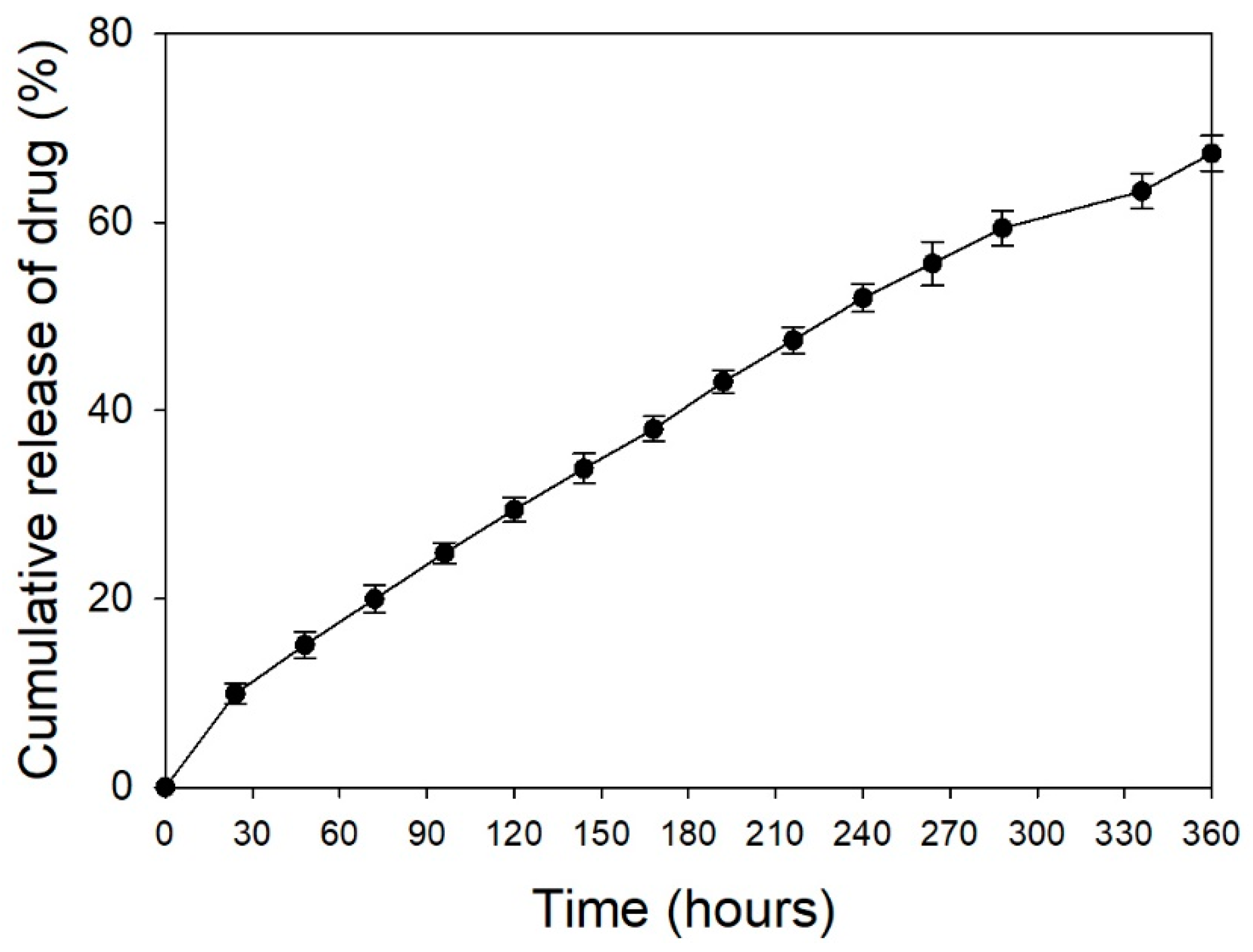
- Dash, S.; Murthy, P.N.; Nath, L.; Chowdhury, P. Kinetic modeling on drug release from controlled drug delivery systems. Acta Pol. Pharm. 2010, 67, 217–223. [Google Scholar] [PubMed]
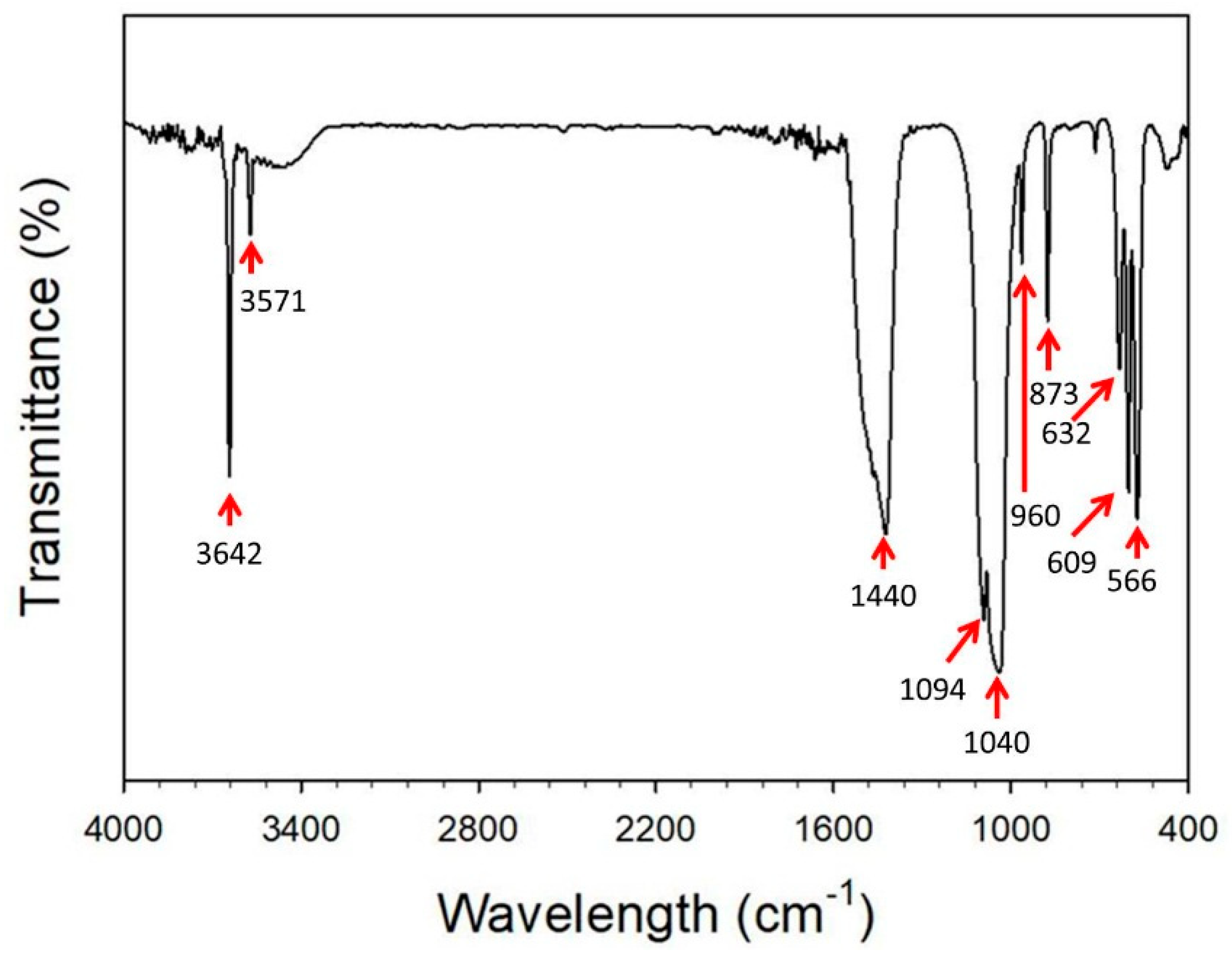
 : CaO, PDF 70-4068;
  : hydroxyapatite, PDF 84-1998;
  : CaCO3, PDF 85-1108).
: CaO, PDF 70-4068; : hydroxyapatite, PDF 84-1998; : CaCO3, PDF 85-1108).
: CaCO3, PDF 85-1108).
: CaO, PDF 70-4068; : hydroxyapatite, PDF 84-1998; : CaCO3, PDF 85-1108).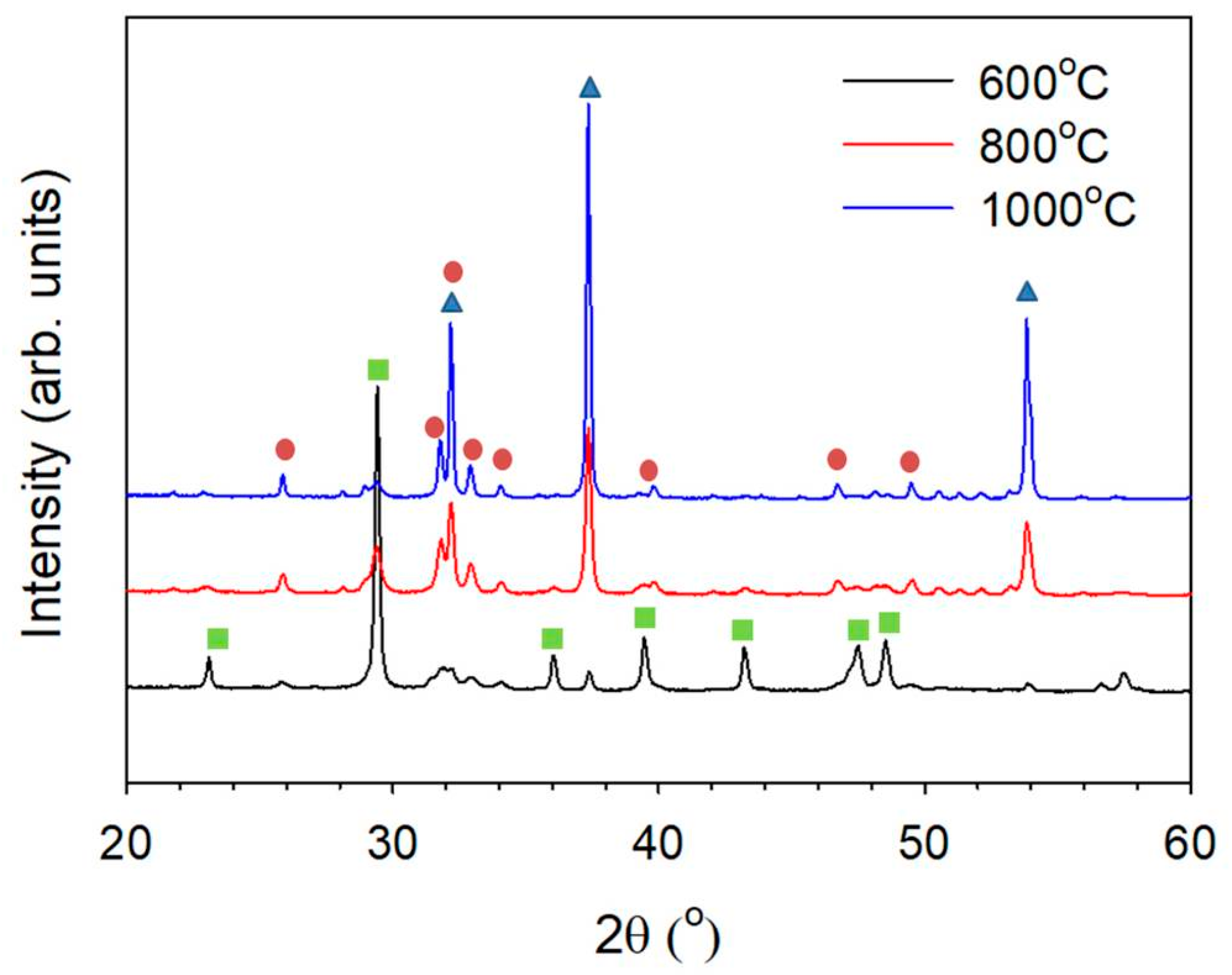 : CaO, PDF 70-4068; : hydroxyapatite, PDF 84-1998; : CaCO3, PDF 85-1108).
: CaO, PDF 70-4068; : hydroxyapatite, PDF 84-1998; : CaCO3, PDF 85-1108).
: CaO, PDF 70-4068; : hydroxyapatite, PDF 84-1998; : CaCO3, PDF 85-1108).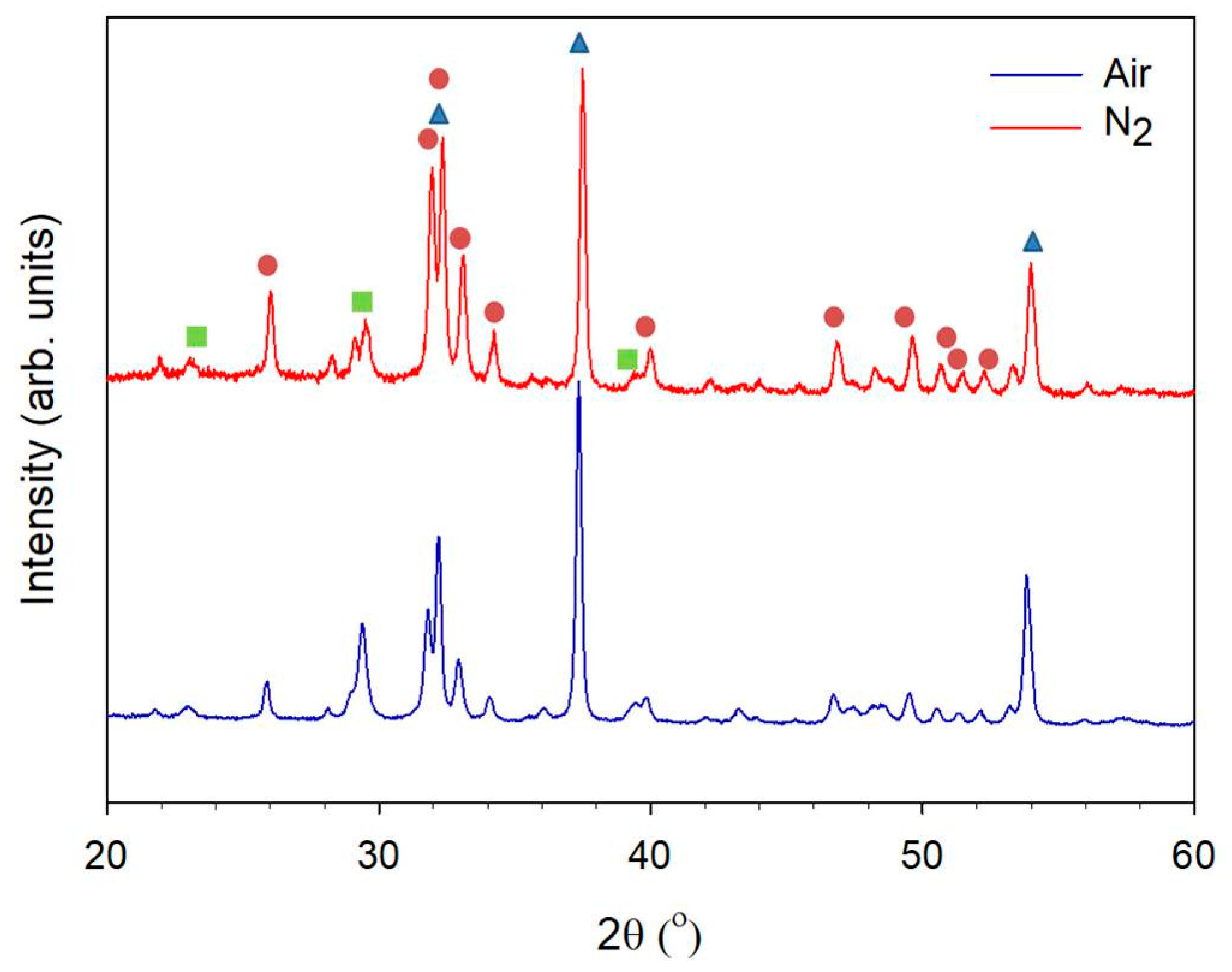


© 2018 by the authors. Licensee MDPI, Basel, Switzerland. This article is an open access article distributed under the terms and conditions of the Creative Commons Attribution (CC BY) license (http://creativecommons.org/licenses/by/4.0/).
Share and Cite
Tsai, S.-W.; Huang, S.-S.; Yu, W.-X.; Hsu, Y.-W.; Hsu, F.-Y. Fabrication and Characteristics of Porous Hydroxyapatite-CaO Composite Nanofibers for Biomedical Applications. Nanomaterials 2018, 8, 570. https://doi.org/10.3390/nano8080570
Tsai S-W, Huang S-S, Yu W-X, Hsu Y-W, Hsu F-Y. Fabrication and Characteristics of Porous Hydroxyapatite-CaO Composite Nanofibers for Biomedical Applications. Nanomaterials. 2018; 8(8):570. https://doi.org/10.3390/nano8080570
Chicago/Turabian StyleTsai, Shiao-Wen, Sheng-Siang Huang, Wen-Xin Yu, Yu-Wei Hsu, and Fu-Yin Hsu. 2018. "Fabrication and Characteristics of Porous Hydroxyapatite-CaO Composite Nanofibers for Biomedical Applications" Nanomaterials 8, no. 8: 570. https://doi.org/10.3390/nano8080570