Abstract
Fibers are widely used in different industrial processes, for example in paper manufacturing or lost circulation problems in the oil industry. Recently, interest towards the use of fibers at the microscale has grown, driven by research in bio-medical applications or drug delivery systems. Microfluidic systems are not only directly relevant for lab-on-chip applications, but have also proven to be good model systems to tackle fundamental questions about the flow of fiber suspensions. It has therefore become necessary to provide fiber-like particles with an excellent control of their properties. We present here two complementary in situ methods to fabricate controlled micro-fibers allowing for an embedded fabrication and flow-on-a-chip platform. The first one, based on a photo-lithography principle, can be used to make isolated fibers and dilute fiber suspensions at specific locations of interest inside a microchannel. The self-assembly property of super-paramagnetic colloids is the principle of the second fabrication method, which enables the fabrication of concentrated suspensions of more flexible fibers. We propose a flow gallery with several examples of fiber flow illustrating the two methods’ capabilities and a range of recent laminar flow results.
1. Introduction
The flow of fiber suspensions occurs in a large number of industrial processes and applications, ranging from paper fabrication [1] to lost circulation problems in the oil industry [2]. A good control of these processes relies on the understanding of the underlying mechanisms, notably the interaction between fibers and flows. These interactions depend strongly on the fiber and flow properties of the given situation and are often found to be complex in industrial applications.
Recent efforts to build lab-on-a-chip applications has created increasing interest in microscopic systems containing fiber-like particles, for example for biomedical applications, drug delivery or micro-filtration devices [3,4]. In this case, the precise understanding of the fiber flow interactions is a necessary ingredient for the development of efficient devices.
Well-controlled model systems are needed to gain this fundamental understanding, and the fabrication of fibers with controlled and tunable properties is crucial. Carbon nanotubes, micro-structures fabricated from soft-lithography-derived-techniques [5,6] or techniques combining capillarities and coating [7] are attractive strategies to fabricate suspensions of microscopic objects with a well-defined geometry and volumic fraction. However, the collection and the suspension of these particles, as well as the injection of the suspension itself into a microfluidic device are problematic issues, which would become even more difficult for flexible particles: clearly, in situ fabrication methods are required to obtain well-controlled systems. It is possible to use microfluidic flow-focusing to fabricate long fibers of different geometries [8], but this approach is limited when decreasing the sizes to tens of microns. In this paper, we present a review of the methods developed in our group, which allow the combination of the microfabrication of fibers and the observation of their flow in microfluidic channels. One of them is based on an existing UV-curing method of micro-objects directly inside micro-channels [9,10], whereas the second uses self-assembly properties of magnetic colloids into chains to fabricate long and flexible filaments.
2. Microfabrication of Suspensions of Polymeric Fibers by Photo-Polymerization
2.1. Principle and Setup Description
We adapted a microscope-based photolithography method initially developed by Dendukuri et al. [11] to produce confined fibers directly inside a microfluidic chip. The idea is to project UV light through a fiber-shaped lithography mask into a microfluidic channel filled with a reactive substance. The solution, a mixture of an oligomer and photo-initiator, crosslinks under UV light: the illumination of the target fluid region through the mask polymerizes it within hundreds of milliseconds. A schematic drawing of the method for fiber fabrication is presented in Figure 1. When using an all-PDMS (polydimethylsiloxane) channel, oxygen diffuses through the PDMS walls and inhibits the radical crosslinking reaction close to the channel walls. The two inhibition layers formed in this way at the upper and lower walls prevent the fibers from sticking to the latter. The light projection along the channel height therefore leads to free fibers with a rectangular cross-section. The inhibition layers can be taken advantage of to adapt the fiber geometry, for example to control the confinement, as we will see later in this article.
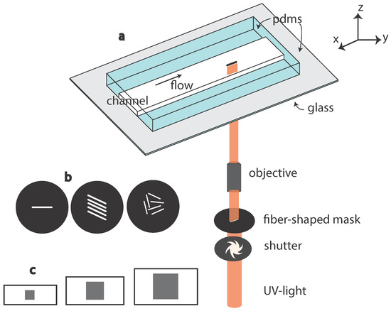
Figure 1.
(a) Schematic drawing of the in situ fiber fabrication technique, using a microscope-based projection lithography technique. UV light is projected into the channel through a fiber-shaped mask, polymerizing the polymer inside the channel, typically within 100 ms; (b) one or several fiber shapes can be used on the mask depending on the number of fibers to make in one step; (c) the polymerization is prevented close to the PDMS walls due to the presence of oxygen allowing free fibers to be fabricated. The thickness of the inhibition layer being constant, the confinement increases with the channel height.
The choice of the oligomer and the concentration of photo-initiator should be made in regards to the targeted mechanical properties of the fabricated fiber [12,13]; see Section 2.3.3. The photo-initiator excitation wavelength should match the light source available and the setup constraints (like the transmission of UV light). Here, we use Darocur 1173 photo-initiator (PI; Ciba Specialty Chemicals Inc., Basel, Switzerland) (2-hydroxy-2-methylpropiophenone, Sigma, Saint Louis, MO, USA), whose excitation peak is around 365 nm. This peak is twice more intense with an HBO lamp as compared to a Xcite120Q source, leading to faster curing with the HBO lamp. For an application requiring softer materials or the presence of water, one can benefit from the solubility of polyethylene glycol diacrylate (PEGDA) in water to fabricate soft hydrogel particles.
As illustrated in Figure 1, we built a fabrication and flow study platform in a single setup. A transparent all-PDMS (Sylgard 184; Corning, Midland, MI, USA) microchannel is made with traditional soft-lithography techniques [12]. It is then placed on the stage of an inverted microscope (Zeiss Axio Observer, Oberkochen, Germany) equipped with a UV light source, a shutter and a fiber-shaped mask (Shutter Uniblitz V25, Lamp HBO 130W, Osram, Munchen, Germany). The UV light is filtered through a narrow-UV-excitation filter set (11004v2 Chroma, Burlington, VT, USA) with an emission peak at 365 nm.
We work with rectangular-section microchannels where the width is up to ten-times larger than the height. The orders of magnitude of channel dimensions are: width 200–500 m, height 20–50 m and a length of several centimeters.
The lithography mask determines specifically the aspect ratio in the plane (x, y) perpendicular to the optical axis. It consists of a transparent-fiber shape drawn in the center part of a 25 mm-diameter black disk. We place this mask in the field stop position of the microscope to get it focused into the objective image plane. The mask is designed with AUTOCAD 2009 and printed at high resolution (50,800 dpi) in order to limit defects on the border line and black spots inside the fiber shape. Anti-UV coated tubings are used to connect the inlet and outlet of the microchannel to a syringe or fluid reservoir, preventing inside polymerization.
2.2. Fabrication Protocol
We describe here the typical workflow of a fabrication experiment. The preparation prior to the experiment involves the design of the mask, the design and fabrication of the microchannel, accordingly, and the placement of the channel and mask on the microscope. We use a mixture of polyethylene glycol diacrylate (PEGDA, Mw = 575, Sigma) (without solvent) with Darocur 1173 photo-initiator (PI) (2-hydroxy-2-methylpropiophenone, Sigma) at 10 wt % and introduce the mixture into the channel by pressure difference. Just before exposition to UV light, we position the chip to get the fabrication of the particle in the chosen location. A camera (PIXELINK, Gloucester, ON, CA) is used for direct observation of the channel. Then, the computer-controlled shutter opens, typically for 200 ms in our setup, and the fiber is crosslinked in the channel. A movie showing the fiber fabrication is available in Supplementary Materials Video S1.
The focusing step is the most delicate one due to the corrections of microscope objectives for achromatic aberrations. It is usually necessary to calibrate the optical system under UV light prior to fabrication, in particular in the case of high-magnification objectives, which have a short depth of field. On our system, using the microscope objective 10×, the focusing done with visible light is corrected with UV light. For objectives 20× and higher, we had to slightly “unfocus” when switching to UV light: for example, a quarter of a full knob rotation for the 40×. This can be avoided using objectives with very small achromatic aberration in UV.
It may be useful to perform the fabrication without stopping the flow [11]. We often worked with a y-shaped microfluidic channel (see Figure 2) allowing, in one of the entry branches, the fiber fabrication with a low-imposed flow rate for high fabrication quality. The second branch was used to adjust the final flow rate, but could be used to inject a different fluid or suspension of particles. We used this fabrication and flow platform to study the flow dynamics of fibers with varying initial orientation [14].
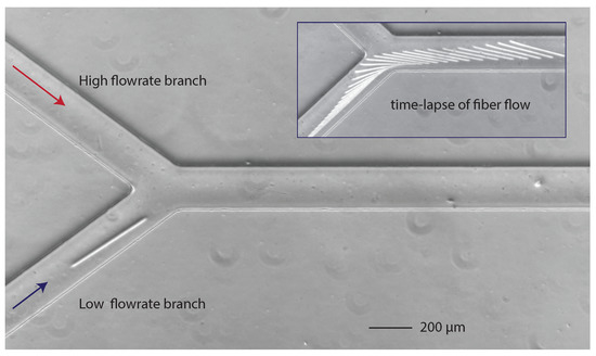
Figure 2.
Y-shaped microfluidic channel for in-flow fabrication with a fiber made in the low-flow rate branch. Inset: successive positions of the flowing fiber.
2.3. Control of Fiber Properties
2.3.1. Fiber Geometry
The lithography technique offers the possibility of making isolated fibers or a fairly limited number of fibers at precise positions inside the channel as illustrated in Figure 3d–f. Their geometry is entirely controlled by the design of the lithography mask. The fiber length and width are proportional to its dimensions, modulo a reduction factor due to both the microscope objective and tube lens. For an objective of a magnitude of 10, we typically obtain a reduction factor of 4.5, increasing to 18.2 for an objective of 40×. This needs to be determined for each experimental setup. Low-magnification objectives were preferred because of their larger depth of field allowing an easier focusing. Typically, the width of fibers is a few tens of microns, whereas their length is a few hundreds.
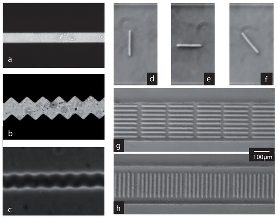
Figure 3.
Examples of photopolymerized fibers. Left panel: (a) example of the mask used to fabricate the fibers. The mask shown here is smooth and will allow the fabrication of smooth fibers like the ones shown in the top row of the right panel; (b,c) the surface roughness of the fiber can be increased by drawing its borders with saw-tooth lines instead of straight ones ((b) mask; (c) resulting fiber). Right panel: top, isolated fibers (d–f); and suspensions of fibers (g,h) fabricated at varying initial orientation. A movie showing the fabrication of the parallel fiber suspension is available in Supplementary Materials Video S1.
As explained earlier, the particle height is given by the channel height and the thickness of the inhibition layers along the upper and lower channel walls. In order to measure this thickness, one can fabricate a particle of a width much smaller than the expected height. As it flows downstream, the fiber turns on its side to lower its confinement, its height appearing in the field of view to be precisely measured. In our operating conditions, we found an inhibition layer thickness of around 6 m. Note that this value is slightly higher than the 2.5 m given in [9], but remains of the same order of magnitude. The fiber height is thus given by the channel height minus twice the thickness of the inhibition layer. For example, for a channel height of 30 m, a fiber height of 18 m is obtained.
The produced fibers do not necessarily need to be smooth, but can also be fabricated with a rough surface. The Figure 3 shows a simple mask (a) and a mask drawn with a saw-tooth contour (b) used to fabricate respectively a smooth fiber (d–f) or a rough one (c). We expect such a roughness to modify fiber-fiber or fiber wall interactions.
2.3.2. Orientation and Concentration
As said before, orientation, inter-particle distance and fiber geometry are entirely determined by the design of the lithography mask, the magnification of the objective used and the placement of the channel on the microscope. When isolated fibers are drawn on the mask, individual fibers of a given geometry can thus be positioned at precise positions inside the channel, varying for example their orientation (see the top row of Figure 3).
A higher particle concentration can be adjusted with the mask; however, one must be careful when fabricating particles very close to each other. There is a threshold distance below which the fluid separating the particles will partially cure during illumination. The threshold distance between two fibers can easily be experimentally determined using lithography masks of two fibers drawn side by side. For a fabrication using the objective 40×, we found it to be 9 m. The right panel (d,e) of Figure 3 shows two examples of a suspension of fibers obtained in this way, all parallel (d) or perpendicular (e) to the flow direction. The fibers’ length is 200 m and the width 14 m, and they are separated by a distance of 12 m.
2.3.3. Fiber Elasticity
We mechanically characterized the fiber through an in situ measurement of its Young’s modulus with an adapted “bending beam” test [13]. The advantages of this in situ test are two-fold. First of all, the test reproduces the exact fabrication conditions used for the micro-fabrication (e.g., UV light intensity, exposure time, etc.), and second, the mechanical properties are tested in the fluid environment used to produce the fiber suspensions. This might be particularly important when working with diluted polymer solutions and, thus, hydrogels. The adapted bending test is the first in situ Young’s modulus measurement method for particles fabricated with the photo-polymerization method.
A fiber is fabricated across a confined microchannel, sitting inside slots, allowing it to deform under the drag force created by the flow. Images of the bending fiber are captured at steps of increasing flow rates, as illustrated in Figure 4. The measurement of the deformation at controlled flow forcing provides direct access to the fiber material Young’s modulus.
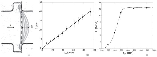
Figure 4.
Adapted from [13] with permission from the Royal Society of Chemistry, 2015. (a) Successive positions of deformed fiber; (b) measured fiber deformation with respect to the flow velocity; (c) results of Young’s moduli for different exposure times. A movie showing the fiber deforming under flow is available in Supplementary Materials Video S2.
The experiment [12,13] was conducted for five formulations in order to explore a range of Young’s moduli. All contain PEGDA at Mw = 575 with Darocur 1173 photo-initiator at concentrations varying from –. Young’s moduli between 1 and 12 MPa were obtained depending on the photo-initiator content and the exposure time, as shown in Figure 4. Note that the nature of the gel, initiator, microscopic optics and projected UV light lamp all lead to a strongly setup-dependent measurement technique requiring an in situ measurement. The modulus can be varied further when working with polymer solutions at different dilutions in water, creating hydrogels with even lower Young’s moduli [15].
2.4. Fiber Confinement and Flow Geometry
As the geometry of the fibers produced using the UV fabrication method depends on the channel geometry through the channel height, fiber dimensions and channel geometry are intrinsically linked. In parallel, the channel geometry also determines the type of flow a fiber or fiber suspension experiences in the channel.
First of all, the fiber is confined in the direction of the channel height. As introduced before, the fiber height is given by the channel height minus twice the inhibition layer. The inhibition layer thickness being constant, the fiber confinement, given by the fiber height over the channel height, can thus be varied by changing the channel height (see Figure 1c). Very specific flow properties result from this confinement and will be discussed in the flow gallery (see Section 5).
Furthermore, the fiber height being comparable to the channel height, to obtain square cross-sections and large aspect ratios (typically a length over width larger than 10), the channel height needs to be small compared to the channel width. This configuration is called a Hele-Shaw cell. In such a flow geometry, a plug flow is obtained in the direction of the channel width, and the shear is localized in the channel height with a small shear layer next to the lateral walls. The fabrication method thus determines not only the confinement of the fiber in the microfluidic channel, but also the overall flow geometry.
3. Microfabrication of Suspensions of Fibers by Colloidal Self-Assembly
We now present a second microfluidic in situ fabrication method to obtain suspensions of flexible fibers at a much higher concentration. We adapted an experimental technique initially developed by Goubault et al. [16] to generate elastic filaments in capillaries. This way, we are able to obtain flexible fibers with a well-controllable geometry, at high concentrations, directly inside microfluidic geometries onto a microscope.
3.1. Principle of Fabrication
The fabrication technique relies on the self-assembly property of superparamagnetic colloids and magneto-stimulated bridging between them. A microfluidic channel filled with a solution of such colloids is placed on the stage of a microscope equipped with a coil to produce a vertical magnetic field. When the magnetic field is applied, each colloidal particle acquires a magnetic moment parallel to the magnetic field B, along the height of the channel. Dipolar interactions are attractive in a solid angle along the direction of the field and with an apex of 55. They induce self-assembly of one-dimensional structures aligned with B. Since the particles are superparamagnetic, once the magnetic field is removed, the colloids move freely and independently in the solution due to Brownian motion. To form permanent filaments, we add polymer to the colloidal suspension. The polymers adsorbed on the surface of each particle will also adsorb to the neighboring particles in the chain (as illustrated in Figure 5) if the surfaces remain close enough during long enough time [17]. There is thus a threshold in the magnitude of the magnetic field above which permanent bridging is achieved and below which the chain will disassemble when the magnetic field is switched off. This threshold is essential to obtain a controlled one-dimensional structure. If particles were simply adhesive, the many collisions that they experience due to their Brownian motion would lead to random aggregation.
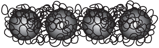
Figure 5.
Super-paramagnetic colloids bridged by a polymer chain, forming flexible fibers.
3.2. Experimental Protocol
The fabrication method consists of three steps as described in Figure 6. Left sketches illustrate each step seen from the side: the height and length of the microfluidic channel are visible. Right-side pictures are extracted from the experiment and show the channel from above. In the first step, the solution of superparamagnetic colloidal particles and polymer in water is introduced into the microchannel placed on the microscope stage (Figure 6(1)). Then, the flow is stopped, and a vertical magnetic field is applied (Figure 6(2)). During this step, the attractive magnetic interactions cause the colloids to self-assemble, and permanent bridging is achieved by the polymer. In the last step, the magnetic field is removed (Figure 6(3)).
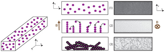
Figure 6.
Principle of fabrication of fibers using super-paramagnetic colloids. Left drawings represent a vertical section view of the channel through the three steps of fabrication, illustrated on the right by frames of the channel captured from above on the microscope, extracted from an experiment.
The superparamagnetic particles are provided by Ademtech (V2G colloids, radius 375 nm, magnetic susceptibility ). They are dispersed at a volume fraction of wt % in an aqueous solution containing wt % of polyacrylic acid (PAA, Mw = 250,000, Sigma) and wt % NP10 surfactant (nonyl phenol ethoxylate, Sigma). The fabrication and flow experiments are done on a Nikon-inverted microscope equipped with a large coil creating a vertical magnetic field in its center. The microchannel is made with traditional soft-lithography techniques. We use a PDMS mold plasma-bonded to a glass slide. It is placed on the microscope stage at the center of the coil. During the fabrication step, we apply a magnetic field of 25 mT for 35 min. Note that any residual flow within the channel at this step would perturb the bridging and prevent the fabrication of the fibers.
The permanently-formed fibers sediment in the channel with random directions. Figure 7 shows a time series of images taken from above of the sedimenting fibers starting when the magnetic field is removed.
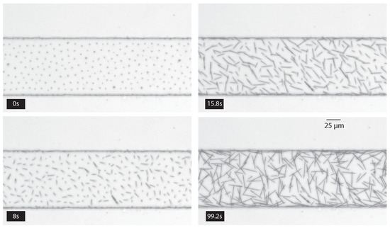
Figure 7.
Successive photographs of the channel from above starting when the magnetic field is removed until the end of the sedimentation of fibers to the bottom of the channel. The channel height (and fiber length) is 28 m. A video of these fabrication steps is available in Supplementary Materials Video S3.
3.3. Control of Fiber Properties
3.3.1. Fiber Geometry
The fibers are characterized by a necklace-like shape: their diameter is given by the diameter of the colloidal particles as illustrated in Figure 5. As the magnetic field is applied in the direction of the channel height, if the magnetic field is applied quickly compared to the sedimentation of the colloids, the fiber length is only limited by the channel height. One can however add a sedimentation step prior to the application of the magnetic field to fabricate filaments shorter than the channel height [18]. In both cases, monodisperse fibers are obtained (see Figure 7).
The fiber aspect ratio can be very large: typical aspect ratios (fiber length over fiber width) are 30–50, but aspect ratios as high as 265 can be obtained [19]. As fibers form as chains of spherical particles, their surface roughness is given by the particles’ radius and could be modified by changing the dimension of the particles.
3.3.2. Fiber Position, Orientation and Concentration
When applying the magnetic field, the vertical columns formed by the assembled colloids show a strong ordering: the dipolar magnetic interactions between columns is repulsive and the equilibrium distance, d, between columns is only determined by their length, L, and [20]. One can see the strong ordering of the filaments, showing a constant distance between chains in top left image of Figure 7. This ordering leads to a homogeneous fiber concentration and random orientation once fibers have sedimented to the bottom of the channel (see Figure 7). One can however take advantage of the fact that the formed fibers are magnetic and can use a magnetic field to orient the fibers in the desired direction (see Figure 8).
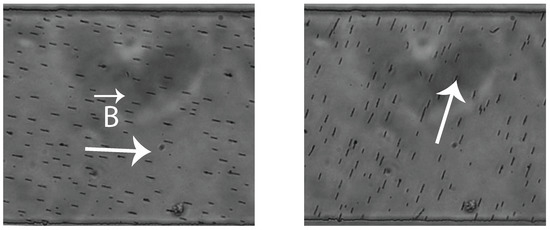
Figure 8.
Photographs of suspensions of short fibers with an imposed orientation using an external magnet.
The maximum concentration of filaments is set by the above-cited relationship between L and d. Below this limit, the fiber concentration in the suspension can be adjusted by tuning the initial volume fraction of colloids. We illustrate this in Figure 9 showing pictures of fiber suspensions fabricated at three volume fractions both during the fabrication (top row) and after sedimentation (bottom row). The channel geometry used for the fabrication is the same for all three bottom pictures with a height of 24 m.
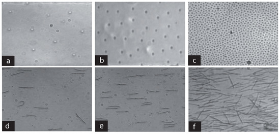
Figure 9.
Variations of fiber concentration with the initial volume fraction of colloids in a given channel. (a–c) The fabrication phase in a 24 m-high channel for three different particle concentrations, leading to a large range of fiber concentrations (d–f). Note that the fibers are aligned with the imposed flow.
3.3.3. Elasticity
Fiber elasticity depends on the nature of the polymer bridging the particles together. A bending modulus of J·m was measured [16] for filaments obtained with the same protocol, colloids and polymer we use in our experiments. A way of increasing the fiber rigidity is to form chains of more than one array of particles. If the volume fraction of particles in solution is increased, it becomes possible to form chains that interact laterally with a half-colloid-long shift (according to the 55). The field threshold to permanently bridge these lateral interactions is larger because the force in directions not aligned with the field is smaller. However, it is possible to use intense-enough fields to generate chains made of two or three rows of particles, as illustrated by Figure 10.
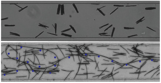
Figure 10.
The top picture shows fibers formed by several chains of colloids bridged together. The bottom picture shows a very long (several centimeters) single-row fiber fabricated in the tubing connecting the inlet of the channel. Blue dots help with locating the fiber.
3.4. Fiber Confinement and Flow Geometry
The fabrication process, using a vertical magnetic field, implies that the length of the fibers is comparable to the channel height. The value of the channel height is thus imposed by the desired length of the fibers to be fabricated. As typically the channel width is two- or three-times the fiber length, channels with a nearly square cross-section are used, in contrast to the channels used for the UV method. This has two important consequences: the flow in the channel is close to a three-dimensional Poiseuille flow [21], as observed in a capillary tube, and fibers are not confined between the top and bottom wall of the channel.
However, as the magnetic fibers are made of colloids filled with iron oxide nanoparticles, they are much denser than water. Thus, when the field vanishes the magnetic fibers sediment to the bottom of the chamber, and all fibers are found in a narrow layer close to the bottom wall. The height of this layer is determined by the Brownian motion of the fibers against the confining gravity forces. One could thus consider this situation as a ’gravity-confined’ suspension.
4. Comparison of the Two Fabrication Methods
Traditional soft-lithography methods for the fabrication of microfluidic channels allow the user to easily design a suitable channel geometry so that the desired fiber design matches the type of flow geometry required. This way, a platform enabling fiber fabrication, observation and two-dimensional or three-dimensional flow is obtained. The two methods of in situ fabrication of microscale fibers presented in this paper are easy to implement on a lab-on-a-chip flow platform, and both allow for a direct flow of fibers downstream a microfluidic channel. These two methods are complementary on the fiber initial position, orientation, geometry, concentration, elasticity and surface characteristics and enable a choice of a number of important features for their flow: the initial state before flow and the flow geometry. We summarize and compare, in Table 1, all of these parameters to provide a clear overview of the fabrication techniques’ capabilities.

Table 1.
Comparison of the two micro-fiber fabrication methods. Typical dimensions are given in italics.
5. Flow Gallery
In this section, we give a number of examples of the flow dynamics of individual fibers and fiber suspensions. These examples illustrate not only the intriguing phenomena that occur during the flow of fiber suspensions, but also give an idea of the large variety of questions that can be treated with the model systems presented in the previous paragraphs. We also specifically present some useful methods to analyze the fibers’ flow dynamics.
5.1. Transport of a Single Confined Fiber
We used the photo-lithography technique to study the transport of individual confined fibers in a Hele-Shaw microchannel. We previously reported [12,14] experimental results completed with numerical simulations, treating in particular the role of confinement and orientation on the fiber dynamics. We have shown that under these confined conditions, a transport anisotropy is observed: a fiber-oriented perpendicular to the flow direction is transported faster compared to a parallel fiber under similar flow conditions [14]. When such an isolated and confined fiber is flowing with an angle (different from zero or ninety degrees) to the main flow direction, it will thus drift with respect to the flow direction and will inevitably approach one of the lateral walls of the microchannel. Hydrodynamic interactions between the fiber and the wall align the fiber parallel to the latter. Any small perturbation will cause the fiber to rotate again and to drift away from the wall with a constant orientation until the interaction with the opposite wall will again lead to fiber alignment. This series of rotation and drift leads to a very regular oscillation of the fiber between the two walls, as illustrated by Figure 11 and described in more detail in [22]. This phenomenon could for example be used as an active mixing method.
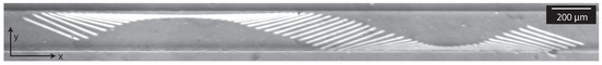
Figure 11.
Time-lapse image of a fiber flowing in the channel. Two hundred milliseconds separate two successive positions. The channel width is 200 m; fiber length 290 m. The corresponding video is available in Supplementary Materials Video S4.
The dynamics becomes more complicated when the fiber is flexible enough to be deformed by the viscous flow (see Figure 12) when approaching the channel walls. Due to the deformation of the fiber, the symmetry between fiber approach and departure is broken. The precise effect of flexibility on the oscillation dynamics remains however still largely unexplored.
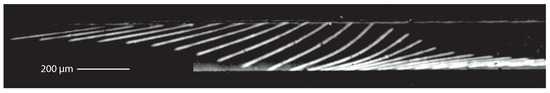
Figure 12.
Chronophotography of an elastic fiber bending during the drift flow.
5.2. Two-Dimensional Dynamics of Fiber Suspensions Near a Flow Constriction
Fabrication of ordered suspensions is illustrated by two cases of different initial fiber orientation in the right panel of Figure 3d,e. In such experiments, the objective was to investigate the flow of ordered suspensions towards a constriction. The lithography mask contains respectively eleven and eight fiber shapes. It is carefully aligned on the microscope to fabricate all of the fibers inside the channel, before manually moving the stage to position the mask upstream and fabricate a new batch of fibers. The operation is repeated as many times as necessary. Fabrication was done at zero flow, then a calibrated hydrostatic pressure was imposed to start the flow. In this case, we designed the channels in such a way as not to allow fibers to flow above each other.
The fiber dynamics at the approach of a constriction was investigated in both configurations (fibers all parallel or all initially perpendicular to the flow direction) [12,23]. Figure 13 shows images of the parallel suspension at different times after the flow is applied. The initial configuration of the suspension is well organized, and when the flow is applied, the fibers in the middle of the first row experience the largest flow velocity and, thus, pass through the constriction. The two outer fibers on both sides are then blocked by the wall of the constriction. When the second row approaches, the outer fibers of the first row are pushed and rotate, allowing the fibers closest to the constriction to pass, while most outer fibers are still blocked. This mechanism is illustrated in the first column of Figure 13 where 200 ms separate the different frames. Then, the suspension disorganizes, breaking its lateral symmetry, and clogging occurs rapidly, as can be seen on the second column of Figure 13. Note that the time between frames in this column is 3 s. From that moment onwards, the flow of fibers into the constriction is drastically slowed down as shown on the third column of Figure 13 where the time between frames is 6 s.
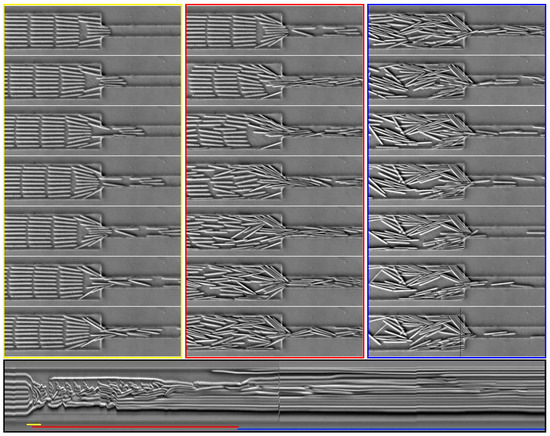
Figure 13.
Time series of images showing the behavior of a suspension of 200 m-long fibers, oriented parallel to the flow, which goes from left to right on the pictures. The first column (yellow) focuses on the initial times (200 ms between frames); the second column (red) shows the lateral symmetry breaking on a longer time scale (3 s after applying the flow, 3 s between frames); and the third column (blue) shows later times (20 s after applying the flow, 6 s between frames). The suspension changes from an ordered spatial organization to a disorganized state, which evolves very slowly. The bottom image is a spatio-temporal representation. Time is represented as the x-axis going from left to right (≈60 s in total), whereas the y-axis represents a line from each picture always positioned at the same place and indicated as a black line on the bottom right image. The colored lines indicate the start and duration of corresponding sets of images shown above. The corresponding video is available in Supplementary Materials Video S5.
The bottom image of Figure 13 is a spatio-temporal representation showing the time evolution of a given area. Here, time goes from left to right, whereas the vertical axis corresponds to the pixels of a vertical line from each picture. Its position on the pictures is indicated by the thin black line on the last frame on the bottom right of Figure 13. This type of representation is very useful to obtain a global view of a time-dependent phenomena. Each elongated bright object corresponds to a fiber passing through the observed line, but the length of the object is not the fiber length, but the duration of the passage. The shorter the object, the fastest the fiber. On the spatio-temporal image, one can identify the passage and reorientation of the first row (from the beginning to the end of the yellow line). Then, in the first half of the red line, the fibers enter the constriction quickly, and the lateral symmetry starts to be broken. From this moment onwards, all horizontal objects on the spatio-temporal image are very long, meaning that the dynamics is strongly slowed down, and the constriction remains clogged.
The observed dynamics are very different in the perpendicular configuration (shown in Figure 14). During the first period (the first column in Figure 14), the first fibers accumulate at the constriction as their orientation prevents them from passing through. Then, they start to bend slightly (as can be seen in the fifth image of this column). The fiber deformation can also be seen in the spatio-temporal image at the bottom of Figure 14, where a black area appears in the last third of the period indicated by the yellow line. Then, the first fibers rotate, breaking the lateral symmetry, and subsequently, clusters of several fibers are formed in the upstream channel, as can be seen in the middle column. Note that the dynamics during this period are faster than for the two other columns (total duration of the first column (yellow): 6 s; middle column (red): 2.8 s; last column (blue): 12 s). The flow of the suspension then becomes very heterogeneous: clusters accumulate on one side, whereas isolated fibers are transported quickly into the constriction at an almost constant speed on the other side (left column of Figure 14). This can be easily seen in the spatio-temporal image, where during the end of the intermediate period (indicated in red) and during all of the last period (indicated in blue), the bright objects have almost the same size. The cluster formation is seen more easily in the second spatio-temporal image showing a cut in the direction of the flow in Figure 15.
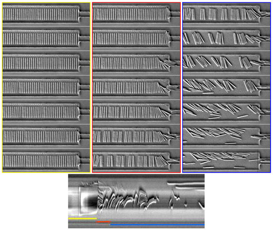
Figure 14.
Time series of images showing the behavior of a suspension of 200 m-long fibers oriented perpendicular to the flow. Flow goes from left to right in the pictures. The first column focuses on the initial times (0.85 s between frames); the second shows the lateral symmetry breaking on a longer time scale (6 s after applying the flow, 0.4 s between frames); and the third one shows later times (10 s after applying the flow, 1.7 s between frames). The suspension changes from an ordered spatial organization to a disorganized state, which evolves very slowly. The bottom image is a spatio-temporal representation of a cut perpendicular to the flow direction. Time is represented as the x-axis going from left to right (≈12 s in total), whereas the y-axis represents a line drawn in black on the last image. Note that the total number of images treated here is smaller than the one used for Figure 13, resulting in a smaller spatio-temporal image. The corresponding video is available in Supplementary Materials Video S6.
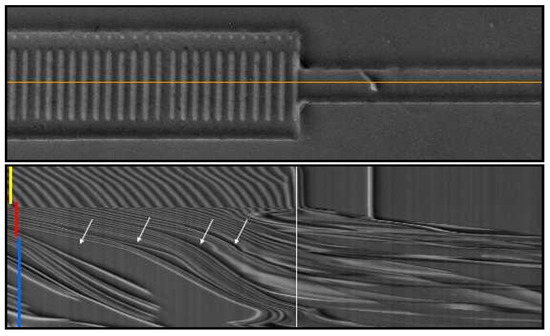
Figure 15.
Spatio-temporal representation of a cut parallel to the flow direction. The top image is the first image of the whole image sequence of the fiber suspension shown in Figure 14. The orange line indicates the cut used to build the spatio-temporal representation of the image sequence shown below. Here, time goes from top to bottom (total duration around 12 s), and the horizontal axis corresponds to the orange line drawn in the picture above. The position of the constriction is indicated in white, and the colored lines indicate the start and duration of corresponding sets of images shown in Figure 14. In this representation, cluster formation upstream of the restriction can be easily seen. The white arrows indicate empty spaces separating clusters.
Finally, Figure 16 shows a suspension of flexible fibers transported perpendicular to the flow direction. The fibers are strongly deformed by the flow when arriving at the constriction. Subsequently, they enter the constriction easily, being still deformed, and only relax back to a straight shape further downstream. Then, quickly, clusters start to form upstream as in the previous example for more rigid fibers (Figure 14). Again, this leads to a lateral symmetry breaking after which fibers go through the constriction as clusters of mainly undeformed fibers, and the dynamics is slowed down. A spatio-temporal representation of these dynamics looks very similar to the one represented in Figure 14 and is thus not shown explicitly.
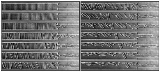
Figure 16.
Time series of images showing the behavior of a suspension of 250 m-long fibers oriented perpendicular to the flow, which goes from left to right in the pictures. The consecutive images (from top to bottom in the two columns) are separated by 1.2 s and the total duration is 18 s. The corresponding video is available in Supplementary Materials Video S7.
5.3. Collective Dynamics of Flexible Fibers Close to the Bottom Wall
We present in this section examples of the flow of fibers fabricated with the colloidal self-assembly method in a microchannel. They represent the flow of a dense suspension of very flexible and rough fibers confined by gravity to a narrow layer close to the channel bottom.
Before the pressure-induced flow starts, the distribution of fibers in the channel is homogeneous (see Figure 7). For high enough concentrations, many collisions between fibers are provoked when the flow is started and aggregates start to form. Contrary to fiber clusters observed in sedimentation, these aggregates are immobilized within the channel. They grow in size as more fibers flow into the channel. We believe that their formation is triggered by fibers slowed down by or adhering to the bottom wall. In the three examples shown in Figure 17, a frame indicates the cluster location, before and after its formation.
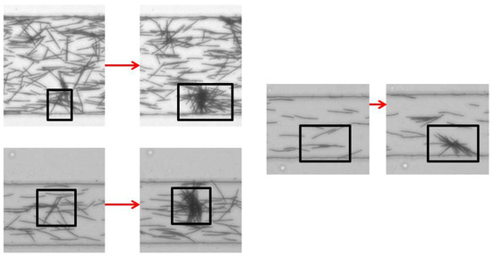
Figure 17.
Three cases of fiber clustering. The first picture is taken before the formation of the cluster. One can note the orientations of the fibers in the cluster, mostly perpendicular to the flow direction. The channel width is 100 m. The corresponding video is available in Supplementary Materials Video S8.
These flocs of fibers are not persistent in the flow and detach after some time. We observed that in most cases, a cluster leaves as a whole; but then, inter-fiber contacts break immediately, and fibers disentangle. A small cluster is usually left behind, probably due to the fact that one or a few fibers were blocked at the bottom wall prior to the clustering. We illustrate such disaggregation of a cluster in Figure 18.
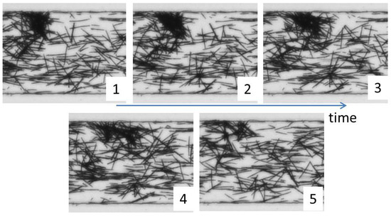
Figure 18.
Disaggregation of a fiber cluster caused by incoming fibers. The channel width is 100 m. The corresponding video is available in Supplementary Materials Video S9.
At even higher concentrations, we observed the formation of a fiber network flowing downstream at a constant velocity. Some isolated fibers remain in the channel and flow faster than the network, which extends across the channel width. Successive pictures illustrate this behavior in Figure 19.
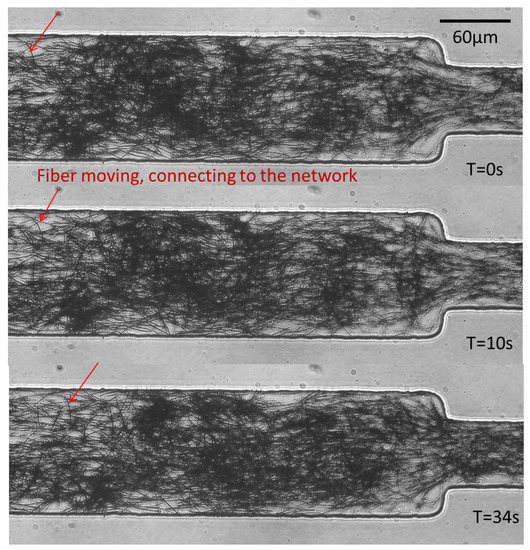
Figure 19.
Formation of a network of fibers, all flowing at the same velocity, extending over the channel width. Fiber density fluctuations can be seen between the three pictures; however, all fibers have flown by the same distance.
6. Conclusions
In this paper, we described two attractive methods to fabricate microscopic fibers directly inside microfluidic channels. Intimately linked with the channel geometry, they provide a large choice for the design of fiber characteristics, such as geometry, mechanical properties or surface roughness. Both techniques are in situ and microscope-based. In the first case, fibers or fiber suspensions are produced by UV-polymerization, whereas in the second method, we use the assembling properties of super-paramagnetic colloidal particles initially introduced in the channel to obtain fiber suspensions.
Flow of single particles, as well as suspensions of fibers at varying concentrations can be easily obtained using these methods, as we have illustrated by a number of examples.
In the future, these methods can be used to tackle fundamental problems on the interaction of complex particles with viscous flows. The better understanding of these fundamental questions might pave the way to the development of sophisticated microfluidic flow separation or analytical biomedical devices. These methods might be used, as well as building blocks for the design of microfluidic devices as flow sensors, or valves, or targeted delivery devices.
Supplementary Materials
Zenodo DOI:10.5281/zenodo.195103 (https://zenodo.org/record/195103). Video S1: Microfluidic fabrication technique of fibers by in situ photopolymerization; Video S2: In situ microfluidic measurement of the fiber’s Young’s modulus; Video S3: Microfluidic fabrication technique of fibers by super-paramagnetic particles self-assembly; Video S4: Fiber oscillating between the two lateral walls of a microfluidic channel; Video S5: Flow through a constriction of a suspension of parallel fibers fabricated by photo-polymerization; Video S6: Flow through a constriction of a suspension of rigid perpendicular fibers fabricated by photo-polymerization; Video S7: Flow through a constriction of a suspension of flexible perpendicular fibers fabricated by photo-polymerization; Video S8: Concentrated suspension of fibers flowing through a microfluidic constriction; and Video S9: Fibers made by colloids self-assembly flowing through a constriction and forming non-permanent clusters.
Acknowledgments
We thank Yoann Maurin for his help with the experiments on the auto-assembled fibers and Osvanny Ramos and Gerard Daccord for interesting discussions on fiber clustering. A.L. acknowledges funding from the European Research Council (ERC) under the Framework Programme Horizon 2020 of the European Commission (Grant Agreement no. 682367).
Author Contributions
H.B., O.d.R. and A.L. conceived and designed the experiments; H.B. performed the experiments; H.B., O.d.R. and A.L. analyzed the data; H.B. O.d.R., and A.L. wrote the paper.
Conflicts of Interest
The authors declare no conflict of interest.
References
- Lundell, F.; Söderberg, L.D.; Alfredsson, P.H. Fluid Mechanics of Papermaking. Annu. Rev. Fluid Mech. 2011, 43, 195–217. [Google Scholar] [CrossRef]
- Gupta, N.; Suhaimi, M.; Taty Taty, B.; Meyer, A.; Forni, G.; de Crevoisier, L.; Rouat, S.; Commerçon, S. Novel Fiber-Based Lost Circulation Treatment Cured Total Losses in Depleted Zones in Emeraude Field. In Proceedings of the Offshore Mediterranean Conference and Exhibition, Ravenna, Italy, 25–27 March 2015; Volume 94, p. 9.
- Jun, Y.; Kang, E.; Chae, S.; Lee, S.H. Microfluidic spinning of micro- and nano-scale fibers for tissue engineering. Lab Chip 2014, 14, 2145–2160. [Google Scholar] [CrossRef] [PubMed]
- Pamme, N. Continuous flow separations in microfluidic devices. Lab Chip 2007, 7, 1644–1659. [Google Scholar] [CrossRef] [PubMed]
- Merkel, T.J.; Herlihy, K.P.; Nunes, J.; Orgel, R.M.; Rolland, J.P.; DeSimone, J.M. Scalable, shape-specific, top-down fabrication methods for the synthesis of engineered colloidal particles. Langmuir 2010, 26, 13086–13096. [Google Scholar] [CrossRef] [PubMed]
- Tavacoli, J.W.; Bauër, P.; Fermigier, M.; Bartolo, D.; Heuvingh, J.; du Roure, O. The fabrication and directed self-assembly of micron-sized superparamagnetic non-spherical particles. Soft Matter 2013, 9, 9103–9110. [Google Scholar] [CrossRef]
- Lee, D.Y.; Pham, J.T.; Lawrence, J.; Lee, C.H.; Parkos, C.; Emrick, T.; Crosby, A.J. Macroscopic nanoparticle ribbons and fabrics. Adv. Mater. 2013, 25, 1248–1253. [Google Scholar] [CrossRef] [PubMed]
- Jeong, W.; Kim, J.; Kim, S.; Lee, S.; Mensing, G.; Beebe, D.J. Hydrodynamic microfabrication via “on the fly” photopolymerization of microscale fibers and tubes. Lab Chip 2004, 4, 576–580. [Google Scholar] [CrossRef] [PubMed]
- Dendukuri, D.; Doyle, P. The Synthesis and Assembly of Polymeric Microparticles Using Microfluidics. Adv. Mater. 2009, 21, 4071–4086. [Google Scholar] [CrossRef]
- Helgeson, M.E.; Chapin, S.C.; Doyle, P.S. Hydrogel microparticles from lithographic processes: Novel materials for fundamental and applied colloid science. Curr. Opin. Colloid Interface Sci. 2011, 16, 106–117. [Google Scholar] [CrossRef] [PubMed]
- Dendukuri, D.; Pregibon, D.C.; Collins, J.; Hatton, T.A.; Doyle, P.S. Continuous-flow lithography for high-throughput microparticle synthesis. Nat. Mater. 2006, 5, 365–369. [Google Scholar] [CrossRef] [PubMed]
- Berthet, H. Single and Collective Fiber Dynamics in Confined Microflows. Ph.D. Thesis, Université Pierre et Marie Curie, Paris, France, 2012. [Google Scholar]
- Duprat, C.; Berthet, H.; Wexler, J.S.; du Roure, O.; Lindner, A. Microfluidic in situ mechanical testing of photopolymerized gels. Lab Chip 2015, 15, 244–252. [Google Scholar] [CrossRef] [PubMed]
- Berthet, H.; Fermigier, M.; Lindner, A. Single fiber transport in a confined channel: Microfluidic experiments and numerical study. Phys. Fluids 2013, 25, 103601. [Google Scholar] [CrossRef]
- Chapin, S.C.; Pregibon, D.C.; Doyle, P.S. High-throughput flow alignment of barcoded hydrogel microparticles. Lab Chip 2009, 9, 3100–3109. [Google Scholar] [CrossRef] [PubMed]
- Goubault, C. Colloides Magnétiques: Auto-Organisation et Applications Biologiques. Ph.D. Thesis, University Pierre et Marie Curie, Paris, France, 2004. [Google Scholar]
- Cohen-Tannoudji, L.; Bertrand, E.; Bressy, L.; Goubault, C.; Baudry, J.; Klein, J.; Joanny, J.F.; Bibette, J. Polymer Bridging Probed by Magnetic Colloids. Phys. Rev. Lett. 2005, 94, 28–31. [Google Scholar] [CrossRef] [PubMed]
- Coq, N.; Ngo, S.; du Roure, O.; Fermigier, M.; Bartolo, D. Three-dimensional beating of magnetic microrods. Phys. Rev. E 2010, 82, 1–10. [Google Scholar] [CrossRef] [PubMed]
- Babataheri, A.; Roper, M.; Fermigier, M.; Du Roure, O. Tethered fleximags as artificial cilia. J. Fluid Mech. 2011, 678, 5–13. [Google Scholar] [CrossRef]
- Jing, L. Field-Induced Structures in Ferrofluid Emulsions. Phys. Rev. Lett. 1995, 74, 2828. [Google Scholar]
- Guyon, E.; Hulin, J.P.; Petit, L.; Mitescu, C. Physical Hydrodynamics; Oxford University Press, Ed.; Oxford University Press: Oxford, UK, 2015. [Google Scholar]
- Nagel, M.; Brun, P.T.; Berthet, H.; Lindner, A.; Gallaire, F.; Duprat, C. Oscillations of confined fibers transported in microchannels. J. Fluid Mech. 2016. submitted. [Google Scholar]
- Lindner, A. Flow of complex suspensions. Phys. Fluids 2014, 26, 101307. [Google Scholar] [CrossRef]
© 2016 by the authors; licensee MDPI, Basel, Switzerland. This article is an open access article distributed under the terms and conditions of the Creative Commons Attribution (CC-BY) license (http://creativecommons.org/licenses/by/4.0/).