Article

A Linear-Elastic Numerical Method and Optimisation Strategies for Dowel-Laminated Timber in Australia

1
School of Civil Engineering, The University of Sydney, Sydney, NSW 2006, Australia
2
Faculty of Civil Engineering and Resource Management, AGH University of Science and Technology, Mickiewicza 30 Av., 30-059 Krakow, Poland
*
Authors to whom correspondence should be addressed.
Appl. Sci. 2026, 16(11), 5330; https://doi.org/10.3390/app16115330
Submission received: 13 April 2026 / Revised: 13 May 2026 / Accepted: 17 May 2026 / Published: 26 May 2026
(This article belongs to the Special Issue Novel Timber Structures and Materials in Building Engineering)

Abstract

Dowel-laminated timber (DLT) is a composite structural material manufactured entirely from wood. Increasing awareness of the sustainability, end-of-life recyclability, and potential health concerns associated with synthetic adhesives used in cross-laminated timber (CLT) and glulam has intensified industry and academic interest in adhesive-free mass-timber systems like DLT. In Australia, however, DLT remains under-researched. This paper addresses global and local knowledge gaps by developing a linear-elastic numerical modelling method for DLT using Australian finite element analysis software Strand7 and investigating structural optimisation strategies, including the use of Australian hardwoods. A finite element model captured the characteristic response of a DLT beam from the University of Liverpool within the linear-elastic range. Reduced dowel spacing, alteration of lamella thicknesses and targeted dowel placement in the shear zones increased global stiffness in the parametrisation study. Incorporating Australian hardwood in the outer lamellae further improved bending performance. Structural viability in the Australian context was indicated through the design of a project-scale DLT beam prototype assessed to relevant Australian Standards. The modelling approach and findings are presented alongside a discussion of behavioural nuances, contributing to the growing body of research on DLT.

1. Introduction

With the building and construction sector contributing approximately 38% of global emissions [1], there has been a significant shift towards reducing the carbon footprint of new buildings by considering climate-sensitive design, increased use of renewable materials and low-impact construction practices, and long-term urban planning. In this context, mass-timber systems such as glulam and cross-laminated timber (CLT) have emerged as prominent construction materials [2]. Despite this, formaldehyde, a known human carcinogen [2], has been identified as a component in adhesives used in glulam and CLT, raising potential health concerns [3,4,5,6].
The use of synthetic adhesives has also been identified as increasing the embodied energy of mass-timber products [7]. In addition, the presence of adhesive compounds complicates their recyclability and end-of-life pathways [8].

1.1. Adhesive-Free Mass Timber and DLT

Awareness of these drawbacks has prompted an interest in adhesive-free solutions that maintain the benefits of mass timber while removing the chemical binders. Dowel-laminated timber (DLT) has emerged as a leading technology in this field. Other adhesive-free technologies include nail laminated timber (NLT) and rotary dowel welding [7].
DLT consists of the binding of timber planks known as lamellae with timber dowels, creating an all-wood structural material [8,9]. The manufacture of DLT is straightforward. Sawn timber lamellae are first assembled into the desired configuration, holes are drilled across the assembled lamellae, and timber dowels are inserted to create a composite member. The lamellae are typically softwood; however, the dowels may be manufactured from densified softwood or hardwood [4,6,7].
Commercial use of DLT has grown in the last two decades, with Han et al.’s review of adhesive- and metal-free technologies reporting over 20 manufacturers operating in Europe in 2022 [7]. An early proof of concept for DLT was Woodcube by Architekturagentur, a five-storey residential building which was designed and constructed as part of the 2013 International Architecture Exhibition (IBA) in Hamburg. The building was constructed from Thoma Holz100 panels in combination with a concrete core, resulting in a building that is 90% pure timber [10]. Despite their viability, DLT systems such as Thoma Holz100 [11] and Rombach NUR-HOLZ [12] rely on certification processes and technical guidelines, and coverage in building standards is limited [7].
Han et al. also summarised 15 studies in academia which typically fell into the streams of experimental studies and numerical studies. Studies like the Sotayo et al. (2020) [8] study “Development and structural behaviour of adhesive free laminated timber beams and cross laminated panels” have established the structural viability of DLT through the physical testing of DLT systems and by comparing them with equivalent glulam counterparts. They recorded beams achieving 70% of the strength of an equivalent glulam beam in a four-point bending test at The University of Liverpool. More recently, the study by Yeh et al. (2024) at the National Cheng Kung University tested DLT beams of compressed wood dowels, finding that increasing the number of dowels along the length of a member increased stiffness, echoing findings of Sotayo et al. (2020) and Xu et al. (2022) [5,8,13].
Studies like Bouhala et al. (2020), O’Ceallaigh (2023) and Ren et al. (2024) used a validated numerical model to allow for the study and optimisation of beams without extensive physical experiments [1,9,14]. All used user-defined subroutines in ABAQUS finite element analysis (FEA) software to capture the elastic and plastic orthotropic properties of wood.
Bell (2018) identified barriers to the market in the UK, such as investigating fire resistance, vibration response, creep behaviour over time, out-door performance under biodegradation and weathering, thermal conductivity, acoustic properties, and environmental life-cycle impact assessment [15].
For a comprehensive literature review of the state of adhesive-free alternatives to mass timber, readers should see “Adhesive- and Metal-Free Assembly Techniques for Prefabricated Multi-Layer Engineered Wood Products: A Review on Wooden Connectors” by Han, Kutnar, Sandak, Šušteršič, and Sandberg [7].

1.2. Essential Structural Concepts

1.2.1. Composite Action

In DLT, lamellae are mechanically interconnected using dowels installed at discrete spacings. As deformation occurs locally at the dowel/lamella interface, the member typically exhibits partial composite action signified by interlaminar slip. Consequently, the global stiffness of a DLT beam is governed by the connection slip modulus, which is influenced by parameters such as dowel diameter, dowel spacing, dowel material properties, and lamella material properties [7].

1.2.2. Gamma Method

The gamma method is a simplified design process used to calculate the bending stiffness and strength for composite mass-timber elements and is detailed in Eurocode 5 [16]. The method is based on the Euler–Bernoulli hypothesis with modifications for composite action between lamellae through the stiffness component  γ i , to produce the effective stiffness  E I e f f in Equation (1) [17]. For DLT, the stiffness component can be determined from physical testing and used to estimate global deflection and bending stress.
E I e f f = i = 1 n E i I i + γ i E i A i z i 2

1.2.3. Shear Flow

Shear Flow is the distribution of shear force per unit length along the interface between elements in a beam Equation (2) [18]. For DLT, the Shear Flow theorem can be used to calculate the average shear transfer required allowing for the design of the connections between lamellae.
q = V I · y ¯ A

1.3. Australian Context

Australia has lagged in the adoption of mass timber in construction [19], and consequently, research on DLT in Australia remains minimal. Studies exploring how DLT could be applied locally, aligned with Australian standards, or adapted to native timber species, are beneficial to bridging this gap.
One study that has done this is Khan et al.’s (2025) exploration of testing approaches for hardwood dowels, from Deakin University [6]. They explored the mechanical characterisation of Australian Tasmanian oak and eucalyptus grandis dowels as the primary connector for DLT, reporting they were the first to do so. They documented the strength and elastic modulus for the dowels which were validated using LS-DYNA FEA software, serving as a library for future studies investigating hardwood dowels [6].
The application of native Australian hardwoods for DLT lamellae is an interesting research avenue, given that Han et al. noted most of the research on DLT has focused on lamellae materials made up of Norway spruce, Scots pine and European oak [7]. Commercial hardwood species such as spotted gum are renowned for their very high mechanical properties, natural durability, and aesthetic appeal, but are challenging for conventional mass-timber applications due to their difficulty in being glued and glue-line delamination leading to frequent failings to meet standards [20]. DLT’s reliance on dowel–lamella contact instead of glue for the transfer of shear force could make it well suited for these hardwoods.
In Australian practice, composite timber beam design is governed by AS1720.1-2010 Timber Structures, Part 1: Design Methods [21]. AS1720.1-2010 does not have explicit provisions for DLT or dowel-type fasteners. For members subject to bending, clause 3.2.1.1 defines the moment capacity where co-efficients take into account the load duration, moisture content, temperature, load sharing, stability, and characteristic bending strength of the wood. While this clause can be used to check some aspects of DLT member strength capacity, assessment of local crushing effects due to dowels and dowel strength are not included. General design and loading criteria for structures are obtained from AS1170.0-2002: Structural Design Actions, Part 0: General principles [22], and AS1170.1 Structural Design Actions, Part 1: Permanent, imposed and other actions [23].
In the broader context, Australia faces a housing crisis with an urgent need for housing supply [24] while striving for global sustainability targets such as net-zero by 2050 [25]. There has been a growing focus on low-carbon construction and rapid, prefabricated housing solutions [26,27], as highlighted by the Australian Building Code Board (ABCB) (2024). Adhesive-free technologies like DLT present an opportunity due to their potential environmental credentials and compatibility with local hardwoods.

1.4. Paper Aims and Novel Contributions

This research paper seeks to strengthen the global and local research base on DLT in Australia by addressing identified knowledge gaps.
In particular, the paper aims to (i) develop and document an analytical elastic numerical modelling approach for DLT using Strand7 FEA software Student Version, capable of reproducing the characteristic linear-elastic response of DLT (Section 2), (ii) apply a validated numerical DLT model, calibrated against a four-point bending configuration, to conduct a parametric study improving structural performance and discussing local dowel effects (Section 3), and (iii) use the outcomes of the parametric investigation to design a project-scale DLT beam, using Australian hardwood lamellae, in accordance with relevant Australian Standards AS1170.0, AS1170.1, and AS1720.1.
The novelty of the paper is found both in an Australian and international context. To the best of the authors’ knowledge, the study of Australian FEA software Strand7 for analysing DLT, and the application of local hardwood lamellae in DLT numerical modelling have not been explored. In a global context, parametrisation insights and presentation of alternative modelling techniques contribute to the growing DLT research base.

2. Numerical Modelling of DLT

2.1. Theoretical Framework and Methodology

Strand7 FEA software was chosen, as it is an Australian finite element analysis (FEA) package used in both industry and research for the structural analysis of complex systems [28].
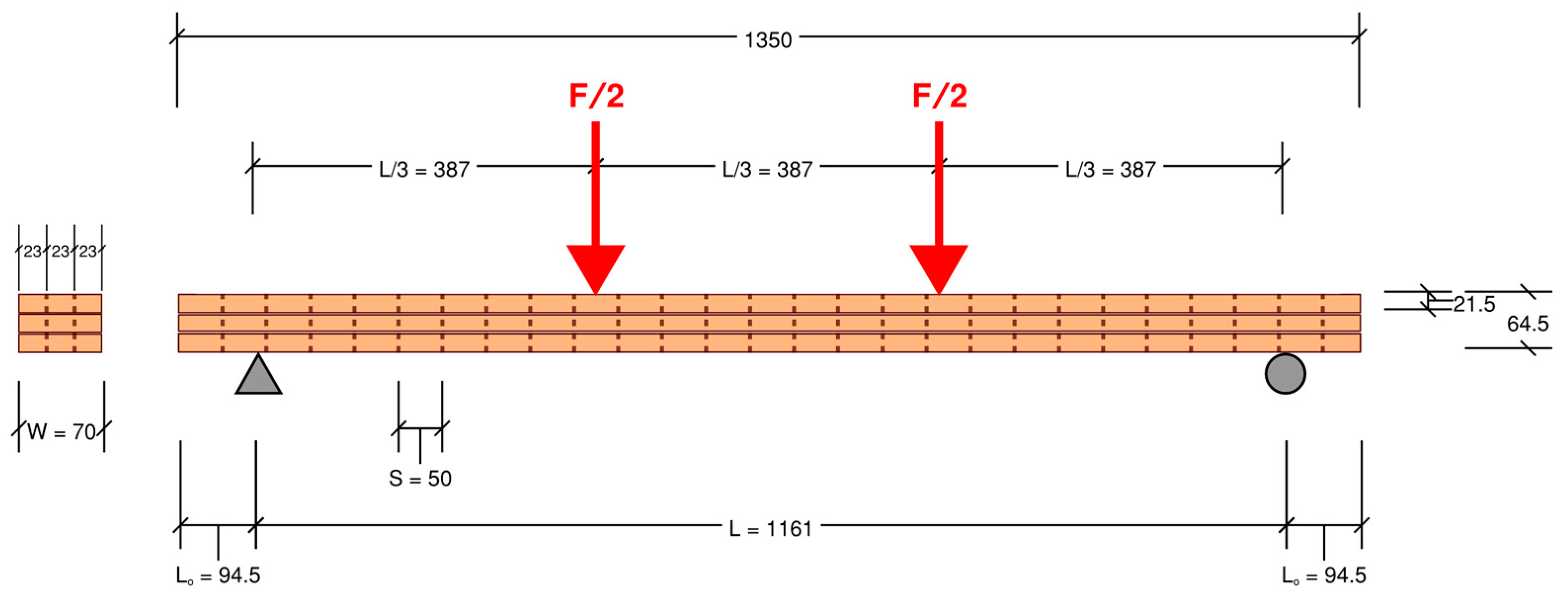
In the absence of a previous study documenting an approach for a DLT beam in Strand7, a validated numerical model approach was used. The AFLT Beam 1 from Sotayo et al. (2020) was selected, due to its 3-lamella arrangement (allowing for minimisation of elements in Strand7), its superior stiffness (4.6 GPa) compared to other beams (3.9 GPa), and its greater sample size (5) compared to the other beams (3) [8]. The four-point bending test and material set-up used throughout the paper is outlined in Figure 1 and Table 1. An iterative modelling approach was conducted, whereby prototypes were compared with the physical test results and refined until the model captured the characteristic response of the physical experiment. The first version was a 2D beam made up of beam elements for dowels and lamellae, and pinned links for the transfer of normal forces. This was further refined to a plate model, then a 3D brick model which captured the partial-composite behaviour of DLT. The key characteristic indicators required for validation were the following:
  • (Experimental). Similar overall deformation profile under four-point bending consistent physical experiments.
  • (Experimental). Observable interlaminar slip consistent with physical experiments.
  • (Structural Theory). Partial-composite stress behaviour for DLT, where (i) a near-composite stress profile is observed at midspan and (ii) shear stresses are observable at the lamella-to-lamella interaction where they are transferred.
  • (Experimental). Similar displacements to the physical experiment.
Once the numerical model was validated as capturing the characteristic response in the linear-elastic zone, it was used for parametric investigation, allowing for the alteration of variables similar to a physical experiment. The following parameters were explored:
  • Dowel Spacing (20 mm, 30 mm, 40 mm, 50 mm, 100 mm, and 200 mm).
  • Dowel Diameter (5 mm, 10 mm, and 15 mm).
  • Lamella Thickness (even lamellae, thinner inner lamella, and thicker inner lamella).
  • Lamella Material (C24 Scots Pine and Australian spotted gum).

2.2. Assumptions, Boundary Conditions and Limitations

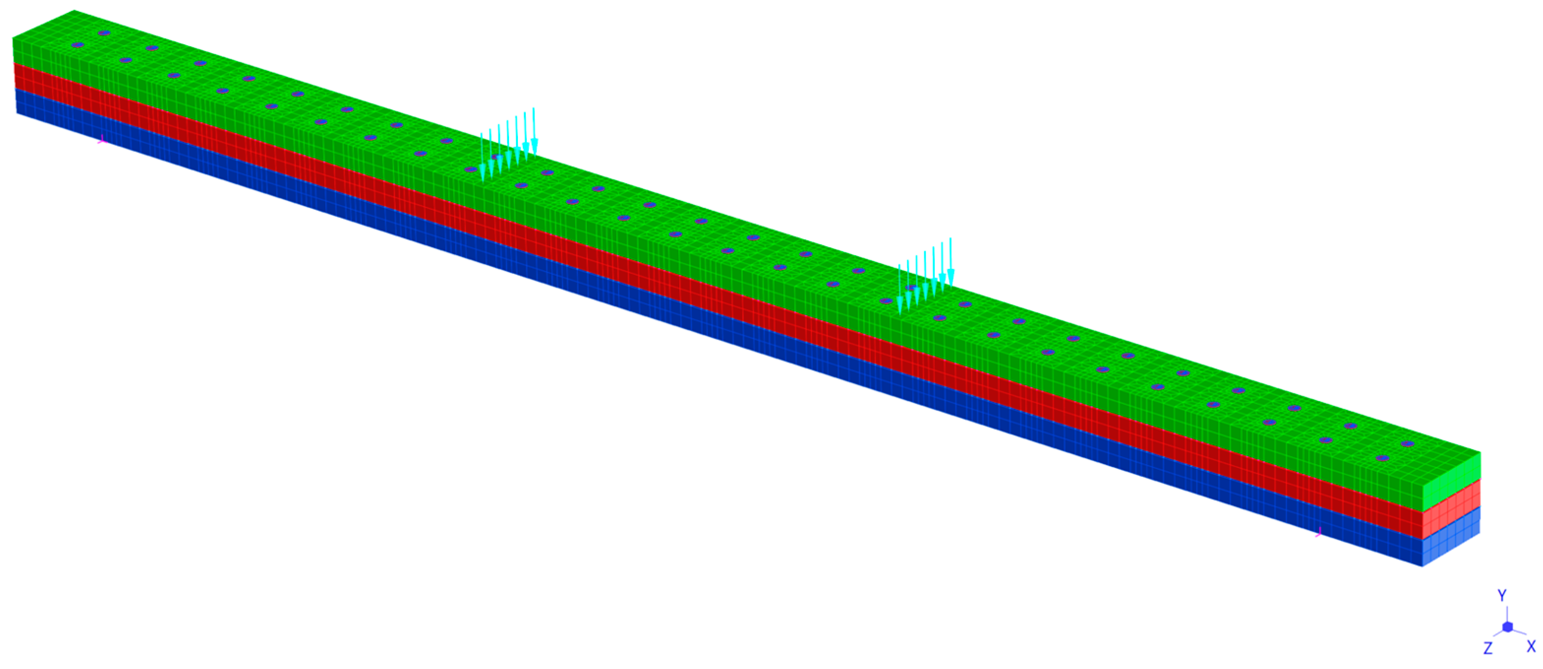
The numerical model used in this paper, shown in Figure 2, utilised assumptions and simplifications to reduce computational demand, explore an analytical approach, and allow for replication without extensive knowledge of FEA software.

2.2.1. Material Modelling Assumptions

The numerical model adopted a linear- elastic orthotropic material formulation throughout, due to software limitations. Strand7 supports nonlinear material behaviour through stress–strain table definitions; however, the available yield criteria are formulated for isotropic materials [29]. For orthotropic materials in Strand7, only linear analysis is specified [30]. This is distinct from platforms such as LS-DYNA, which supports non-linear models with orthotropic material properties, as used by Khan et al. (2025) [6].
The material properties used in the numerical model are shown in Table 2. As the material properties for the C24 Scots Pine Lamellae were not published, values from EN 338 Table 1 [31] were used. The shear modulus of compressed-wood dowels was also not reported; instead, it was estimated by scaling uncompressed C24 Scots Pine using the ratio of elastic moduli. Both substitutions introduce uncertainty into absolute stiffness predictions. Given that EN 338 values represent mean grade properties, the lamella substitution is unlikely to introduce systematic bias in either direction; however, it prevents exact replication of the physical specimen. The dowel shear modulus estimate could introduce error in either direction; however, its contribution to global stiffness is estimated to be secondary to the longitudinal elastic modulus of the lamellae.
Orthotropic material properties were assigned to the brick elements using the longitudinal and perpendicular elastic moduli sourced from EN 338, in the absence of published radial and tangential properties from Sotayo et al. [8]. For the 4-point bending test, the longitudinal modulus is expected to govern the global stiffness response, so omission of radial–tangential distinction is expected to have a negligible effect on global deflection predictions.
For the spotted gum models, the longitudinal elasticity was obtained from WoodSolutions Australia as 19 GPa [32]. In the absence of shear properties and elastic properties perpendicular to the grain, longitudinal/perpendicular ratios for a comparable hardwood American white oak were obtained from the USDA Wood Handbook [33]. Note the tangential and radial values were averaged to obtain the perpendicular ratio. Similarly to above, both assumptions introduce uncertainty into the absolute stiffness predictions.
As the model assumed homogeneity in material behaviour, the inherent variability of timber such as knots, grain deviation, and density variation was neglected. With visual defects observable in the AFLT sample of the Sotayo et al. study [8], this would have led to slightly higher stiffness and strength in the numerical model.
The dowels were constructed from 2D beam elements to simplify the dowel–lamella interaction. Strand7 does not allow for orthotropic properties to be assigned to beam elements, so isotropic mean-modulus of elasticity and shear-modulus values were assigned which would lead to higher global stiffness. Similar to above, as the effect of dowel properties are estimated to be secondary to the lamella properties, the impact on global stiffness is estimated to be minimal.
The mesh grid was typically 10 mm, with more detailed refinement at dowel interfaces to capture local effects.

2.2.2. Contact and Interface Assumptions

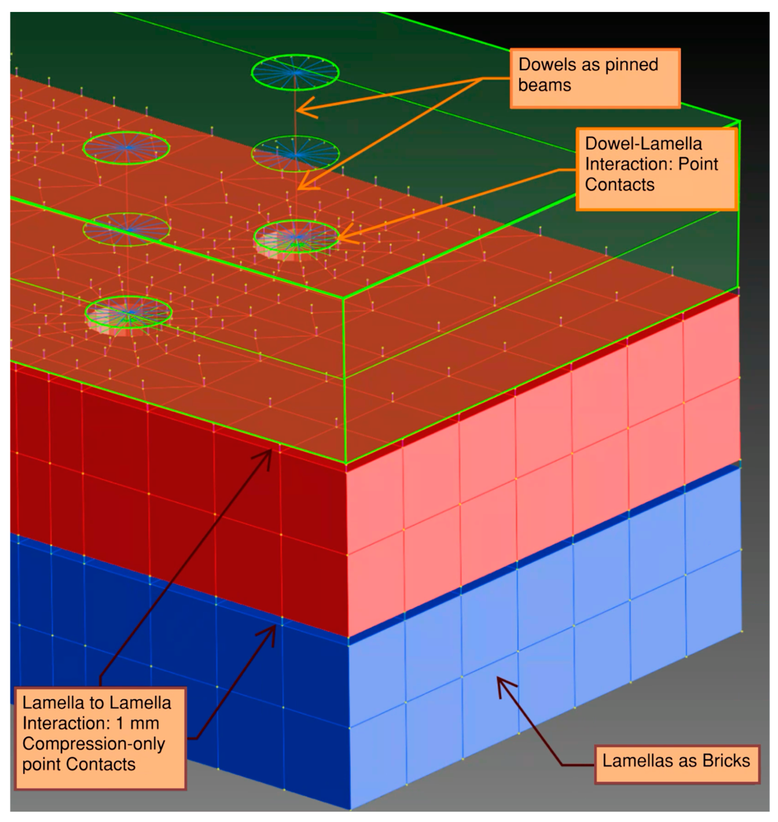
Figure 3 shows key model components. The dowel–lamella interface was modelled using compression-only point contacts assigned an infinite stiffness at three locations per lamella. These represented the normal forces being transferred between the dowels and lamellae. At a global level, the impact on overall deflection is expected to be limited; however, for local stress results, spikes were observed at these locations. While these are physically indicative of the bearing stresses that develop where dowels bear against the lamella face, the point-contact idealisation concentrates force transfer at discrete nodes, rather than distributing it over the physical contact area. The magnitude of these local stresses should therefore be interpreted with caution, rather than taken as quantitatively accurate predictions of bearing stress.
In addition to the point contacts, 2 rigid links for each dowel at the centroid of the centre lamella were necessary for model convergence. These members likely restricted realistic dowel rotation, potentially leading to a modest overestimation of global stiffness.
The lamella–lamella interface was also modelled using compression-only point-contacts assigned an infinite stiffness. These elements represented the normal forces transferred between the lamella. The use of nodal point contacts introduces a simplification in the modelling; however, as the mesh density was fine, any impact is considered negligible. As they were compression only, friction between lamellae due to surface roughness or compression is not accounted for. The shear resistance due to the friction was considered negligible in proportion to the shear resistance provided by dowels. A 1 mm gap was introduced between the lamellae to prevent unintended node merging and contact overlap within the mesh. This gap would likely decrease global stiffness results; however, given its small magnitude relative to the overall beam depth, its influence on predicted load-deflection response is expected to be negligible. Loads were applied as plate forces across a 10 mm width. Elevated local stress or deformation was not observed at these points in the numerical model, as with the nodal supports at each end.

2.2.3. Data Processing Method

A nonlinear static solver was used with discrete load increments of 1 kN from 0 to 8 kN, enabling the load-displacement response at midspan to be tracked incrementally and compared against the experimental data of Sotayo et al. (2020) [8]. Global stress results were reported as Von Mises stresses at element centroids. For localised stress investigations at dowel locations, nodal stresses were extracted to capture peak values at the contact interfaces.

2.2.4. Validation Scope

The model was validated against a single beam configuration, AFLT Beam 1 from Sotayo et al. (2020) [8], in a four-point bending configuration within the linear-elastic loading range of 2 kN.

2.2.5. Time-Dependent and Environmental Effects

Creep, shrinkage, and moisture-induced relaxation were not modelled, meaning that all results correspond to short-term loading conditions. For bending strength assessment in Australia, these factors are accounted for within the moment capacity in AS1720.1-2010 clause 3.2.1.1; however, for long-term serviceability assessments, appropriate long-term modification factors would need to be applied to the model outputs.

2.2.6. Parametric Study Limitations

The parametric study examined each variable independently, meaning interaction effects between parameters was not investigated. As a first-principles study, a single-variable approach was deemed appropriate, with the focus being to establish clear directional trends and compare them with the experimental results.
Overall, the combined modelling and validation assumptions mean that the study’s findings should be interpreted qualitatively, rather than quantitatively.

2.3. Verification, Calibration and Limitations of Final Model

2.3.1. Verification According to Structural Theory

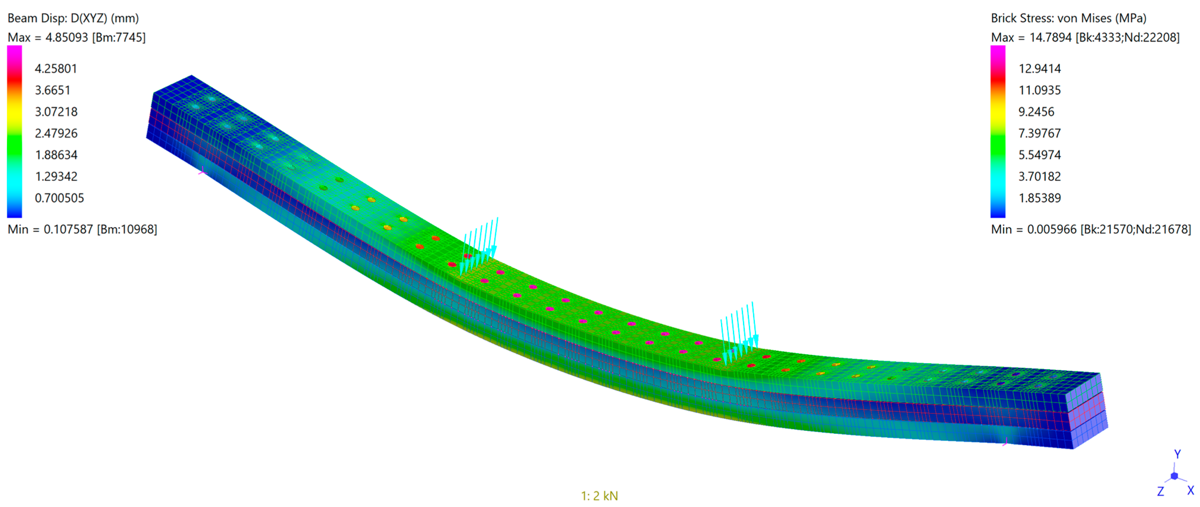
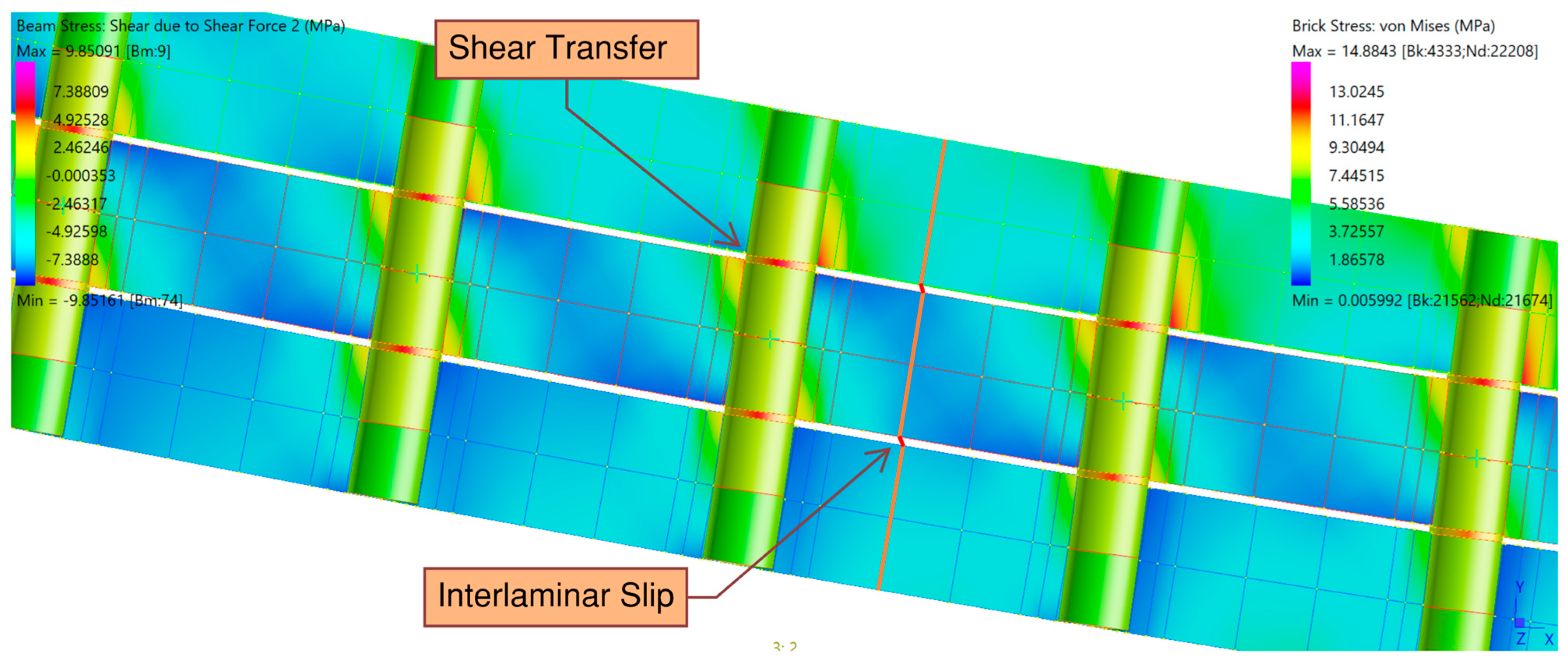
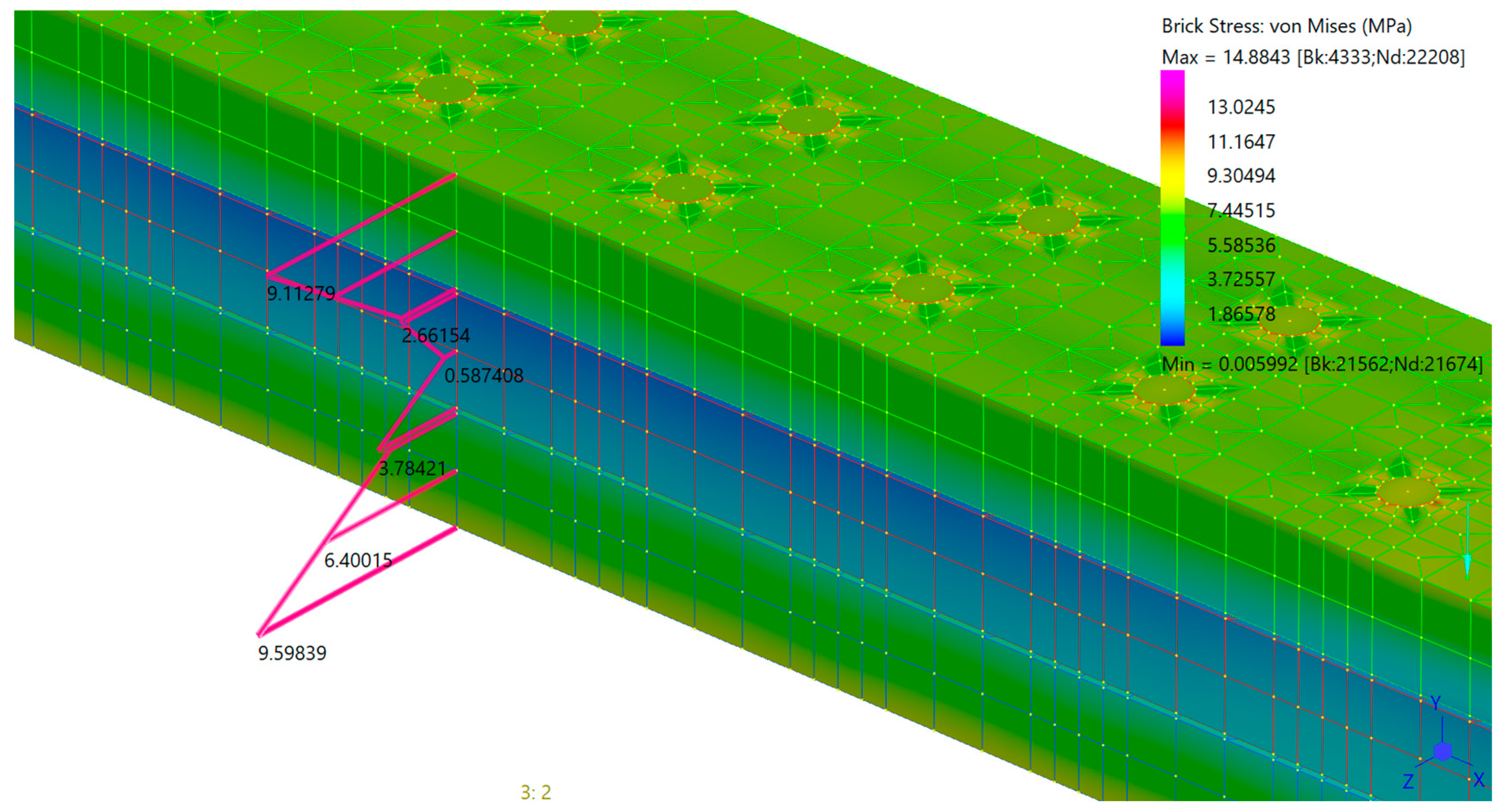
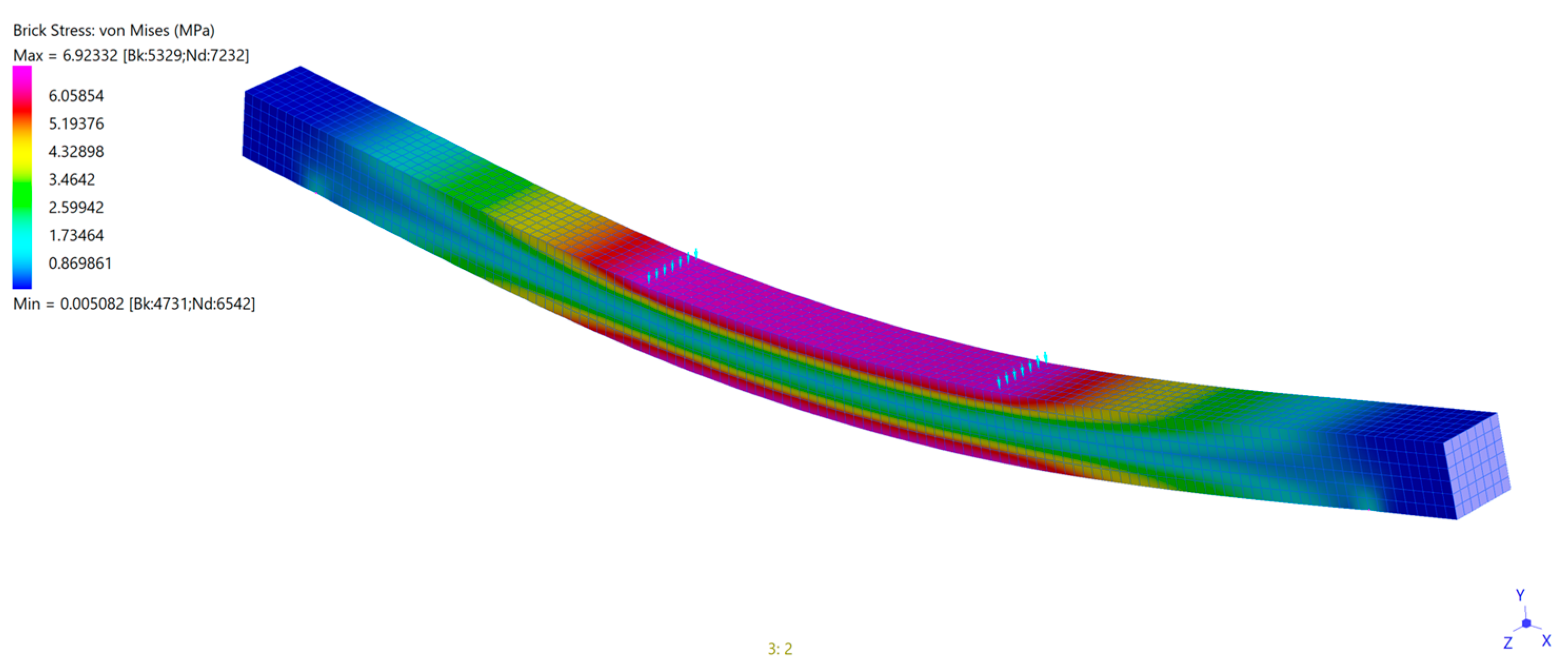
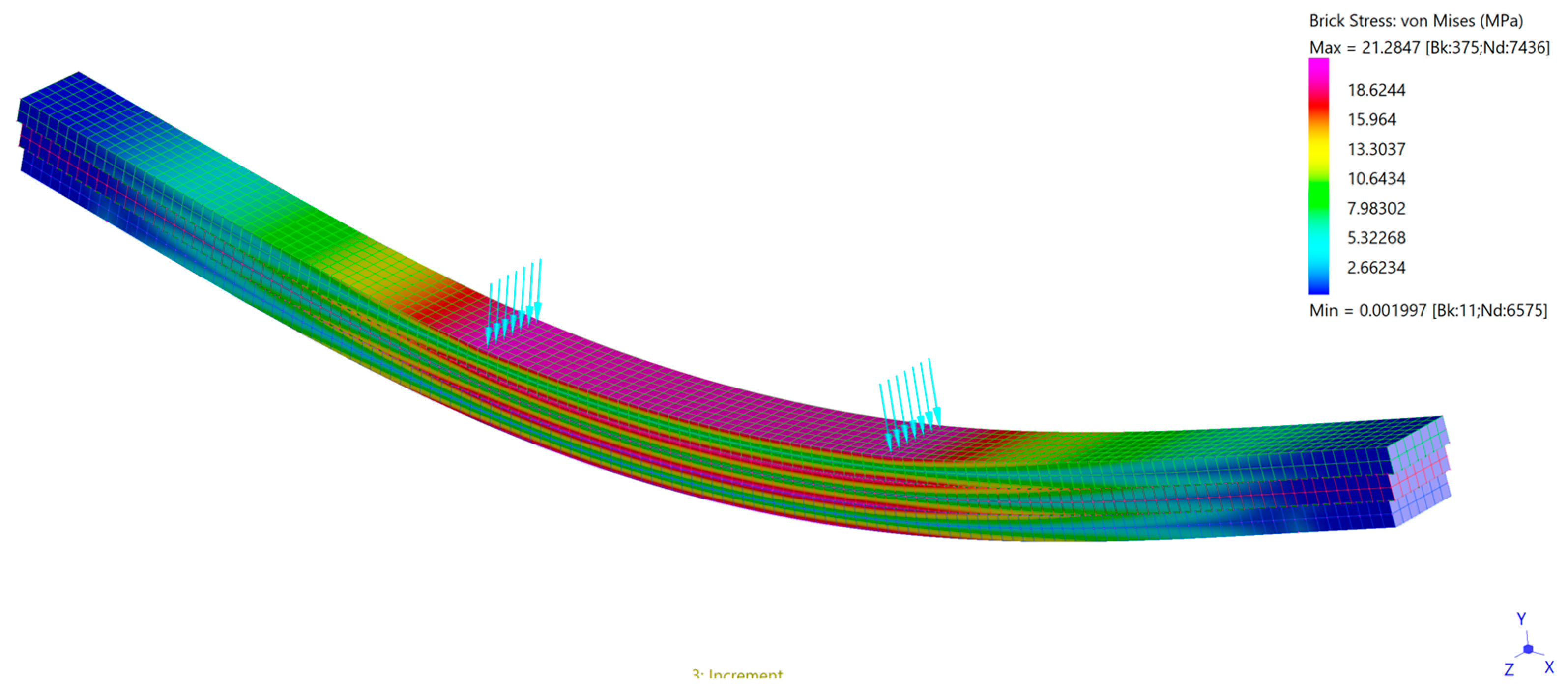
Figure 4, Figure 5 and Figure 6 show the bending and stress results for the numerical brick model at 2 kN. Figure 6 shows the stress profile taken at mid-span, showing the expected bending behaviour characterising composite members. In Figure 5, a section is shown in the shear zone of the beam, between the left-hand support and left-hand load cell. The transfer of axial forces onto the dowel is shown clearly in the beam stress at the lamella interface, resulting in a bending moment on the dowel, which results in local stresses on the lamellae.

2.3.2. Verification According to Experimental Results

The overall deformation pattern of the numerical model (Figure 4) demonstrates a clear correlation with the experimental deformation profile, where the beam exhibits central deflection under the two point loads with rotation at the supports [8]. Both the physical and numerical beams display characteristic curvature of a four-point bending system, indicating that the model accurately captures global stiffness and boundary conditions.
Observable interlaminar slip due to the embedment deformation is shown in Figure 5. While the Sotayo et al. 2020 study did not present a section of the AFLT Beam 1, similar deformation patterns were observed in their Beam 2 sample [8]. Comparable interlaminar slip and dowel-embedment were also documented by O’Ceallaigh et al. (2023), in their 3-lamella DLT beam, and Xu et al. (2022) in their 3-lamella dowel-laminated CLT timber study [5,9].
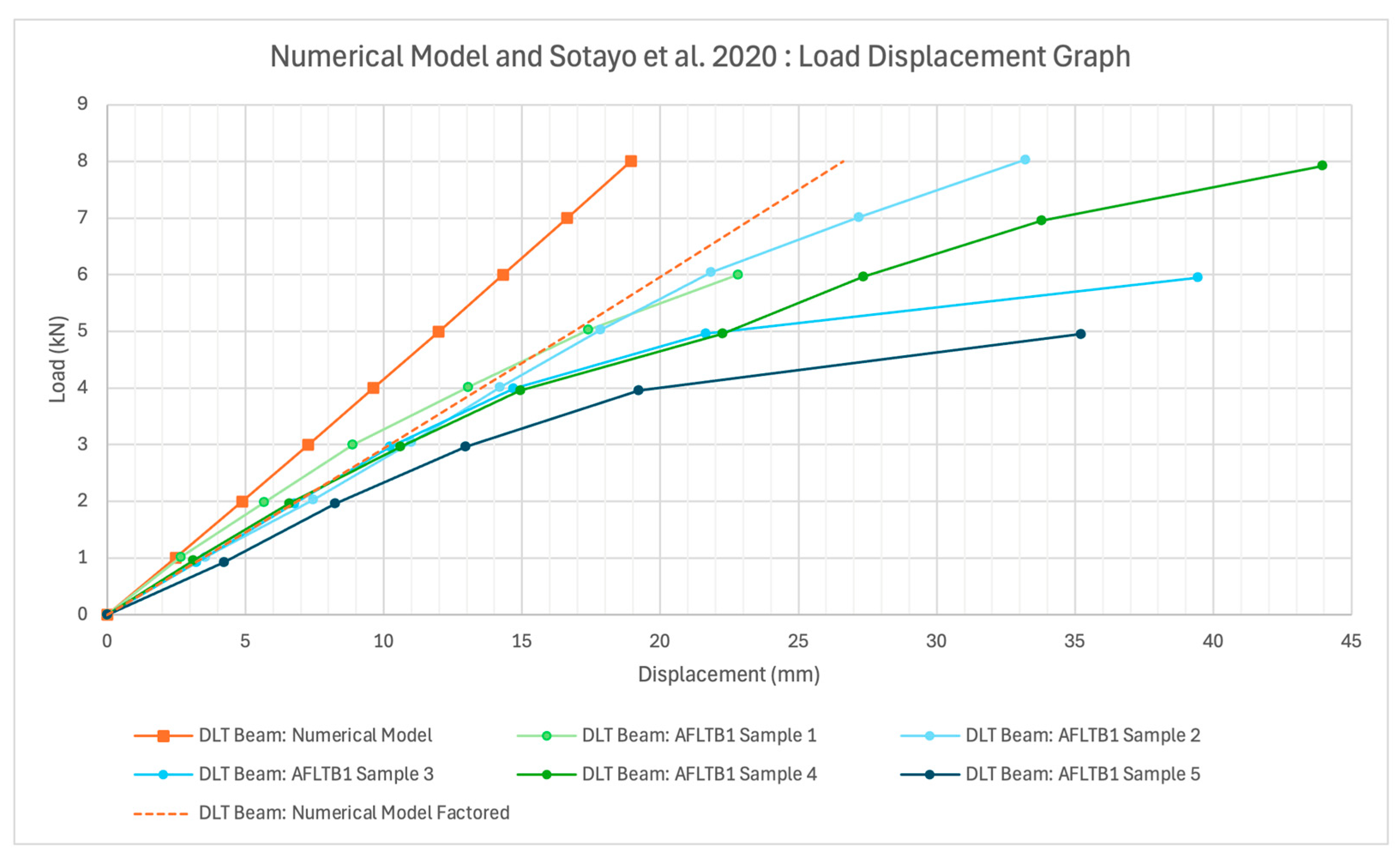
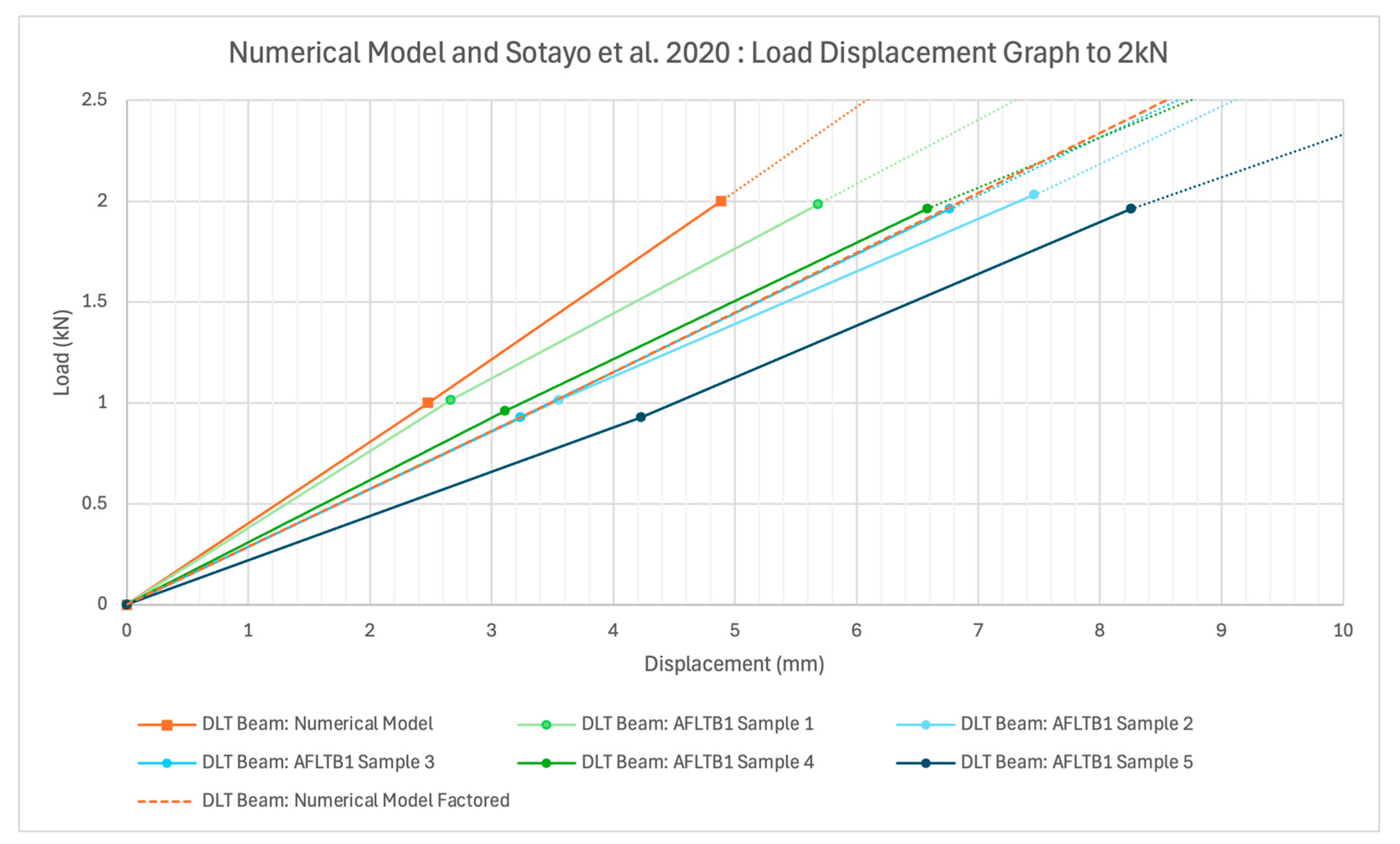
Figure 7 shows the numerical model results plotted against the experimental results from the Sotayo et al. study [8], with Figure 8 showing the results to 2 kN. Comparing the results from the brick model to the results from the five samples of AFLTB1:
  • The numerical model undergoes linear-elastic deformation up to 8 kN, while the physical beams appear to undergo linear-elastic deformation up to approximately 2 kN, after which they undergo plastic deformation (as shown by the curvature of results after which point). This is shown in Section 3.3, where at 2 kN average compressive, tensile and bearing stresses for the numerical model are shown to be within limits.
  • The deflection of the numerical model remains comparable to the mean deflection of the physical beam at 2 kN, where a difference of 29% using a line of best fit was recorded, forming the basis of the reduction factor used in “DLT Beam: Numerical Model Factored.” AFTB1 Sample 1 records an average deflection difference of 14% up to 2 kN, demonstrating reasonable agreement. The overestimation of stiffness is likely due to both the modelling simplifications and idealised material assumptions.
  • The stiffness of the experimental beams varies significantly, even within the linear-elastic zone, with AFLTB1 Sample 5 recording 1.6 times the deflection of Sample 1 at 1 kN. This indicates significant variability in the timber qualities, as noted by Sotayo et al. in their study [8].
The validation range of 0–2 kN corresponds to a mean experimental midspan deflection of 6.89 mm, equivalent to a span-to-deflection ratio of approximately span/168. This exceeds the suggested serviceability limits for floor beams prescribed by AS 1170.0, which range from span/250 to span/500, indicating that the 0–2 kN load range is representative of realistic in-service conditions.
Overall, while the numerical model overestimates stiffness, it captures the partial-composite behaviour of the Sotayo et al. AFLT Beam 1 [8], and reproduces similar deformation trend in the linear-elastic zone. This validates the numerical model’s suitability for the subsequent parametric studies, with the behaviour being used to illustrate the broader behaviour of DLT.

3. Optimisation of the DLT Numerical Model

3.1. Comparison with a Solid Beam, Beam Without Dowels, and Glulam

3.1.1. Solid-Beam Numerical Analysis and Verification

A solid beam (Figure 9) of the same dimensions in Figure 1 was modelled in Strand7 and verified using the gamma method. The stress results of the beam for 2 kN are shown below in Figure 9, showing a typical linear-elastic stress profile at mid-span, an indicator of homogenous or fully composite behaviour.

3.1.2. No-Dowel Numerical Analysis and Verification

A model with dowels removed is shown in Figure 10. The lamellae act independently, slipping against each other and displaying their own linear-elastic stress profile, indicating non-composite behaviour. This model was again verified using the gamma method, where the gamma coefficient  γ i was zero.

3.1.3. Glulam Model

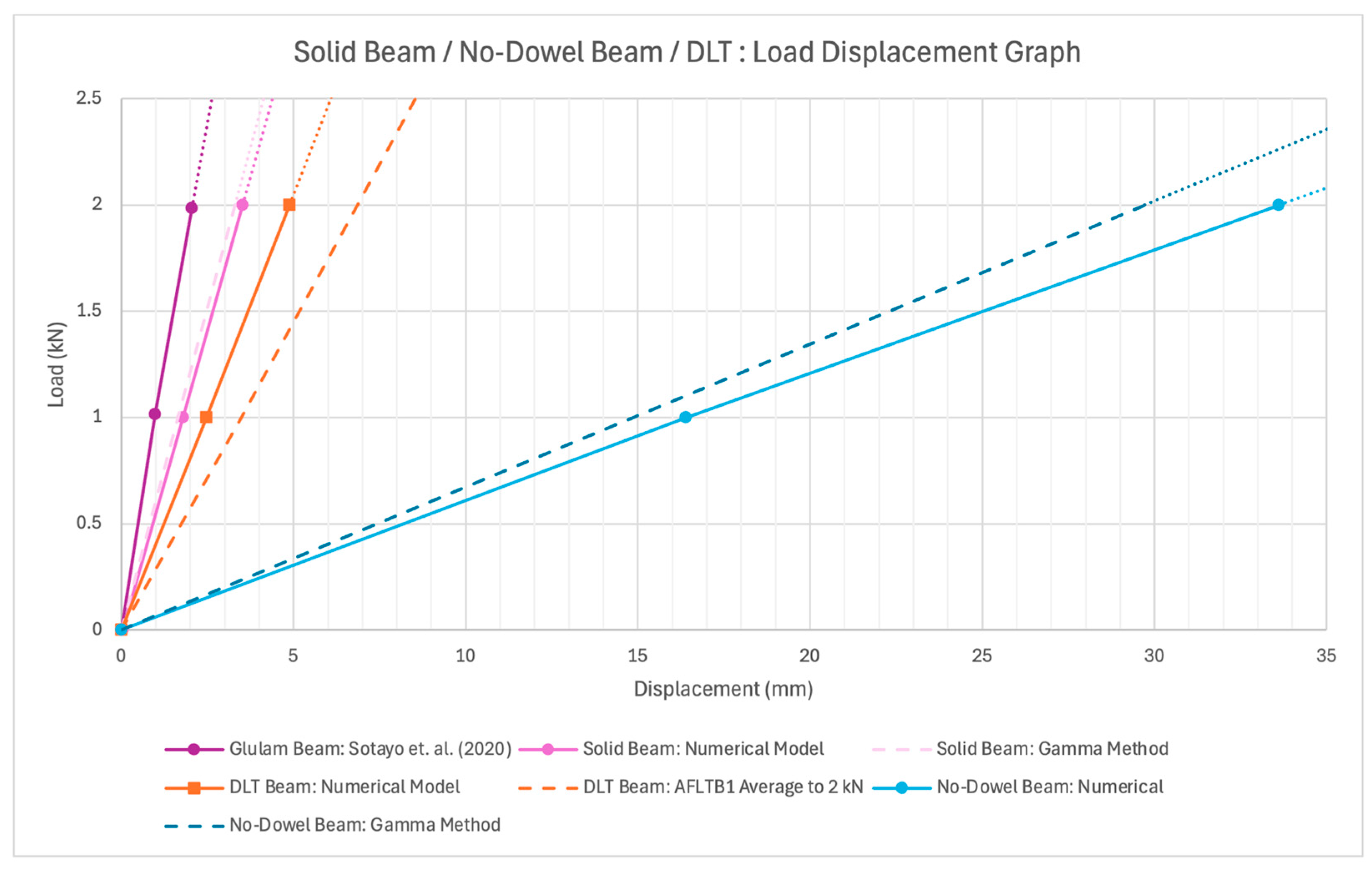
The Sotayo et al. 2020 study [8] tested glulam beams of the same dimensions as the AFLT Beam 1 [8]. The study reported they were both made from C24 Scots pine, so it serves as a fully-composite comparison to the DLT model. The results from the study are plotted below, in Figure 11.

3.2. Dowel Spacing

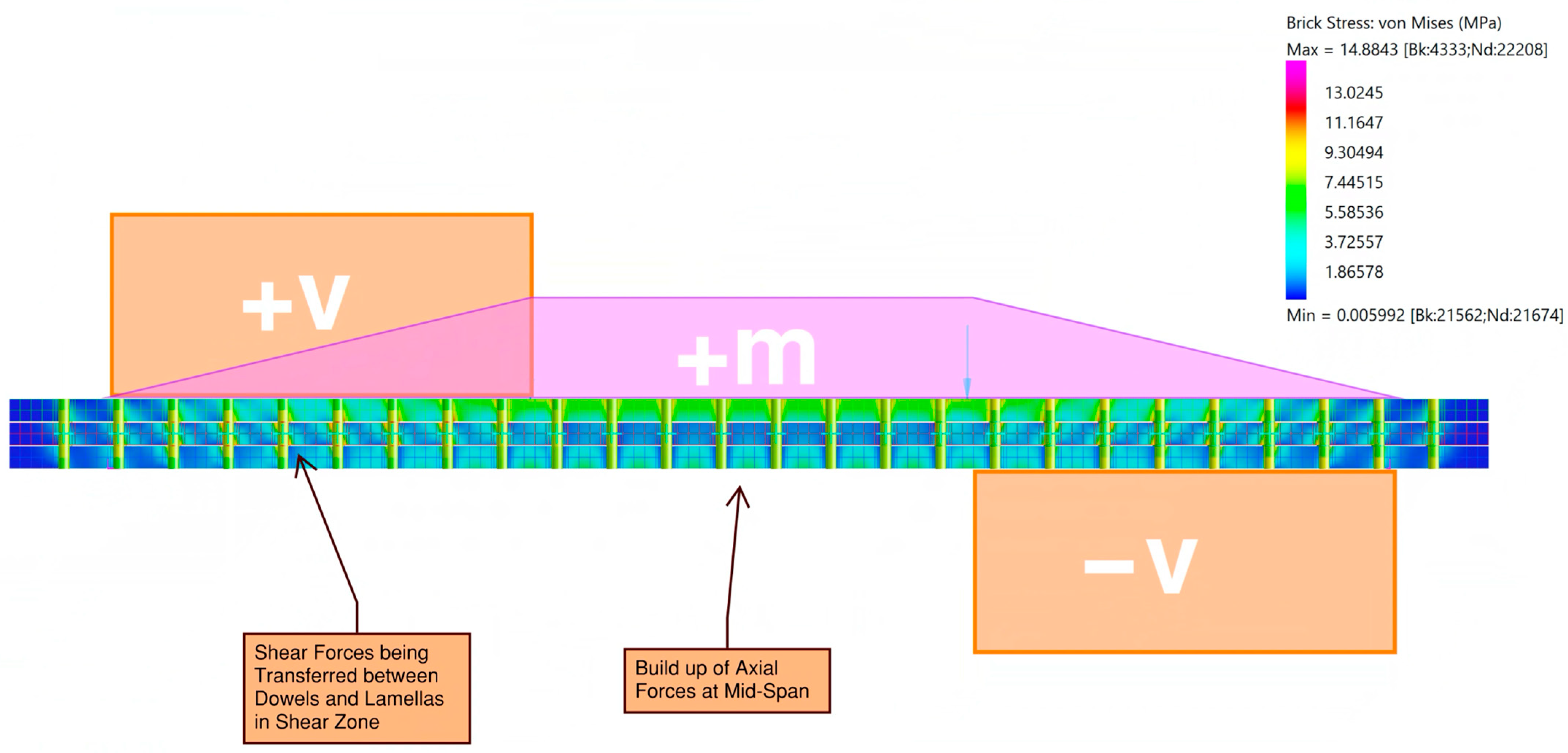
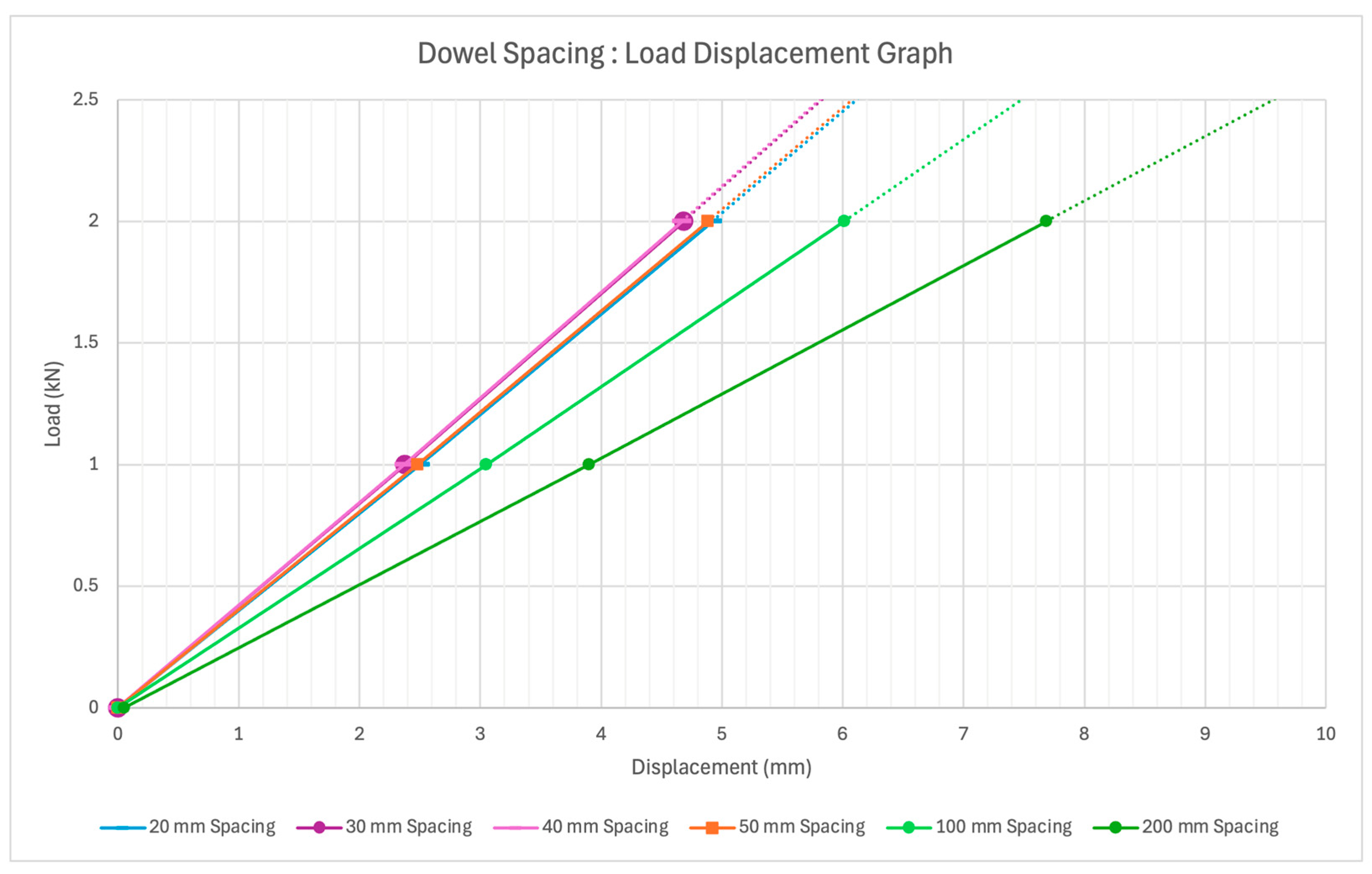
The effect of dowel spacing on global stiffness was explored with results shown in Figure 12. Shown below in Figure 13, is the bending moment and shear diagram overlayed on a section of the numerical model, with the ends extending past the supports neglected.

3.3. Dowel Diameter

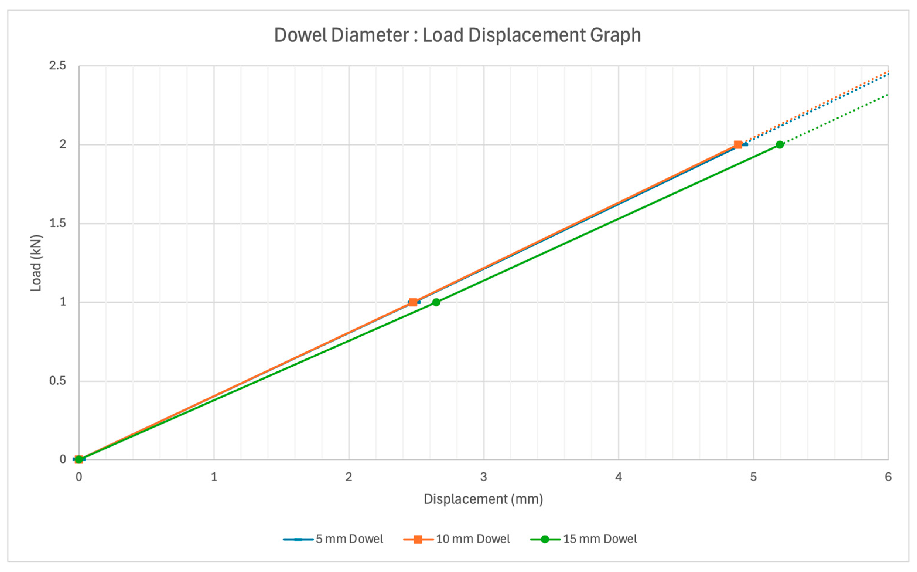
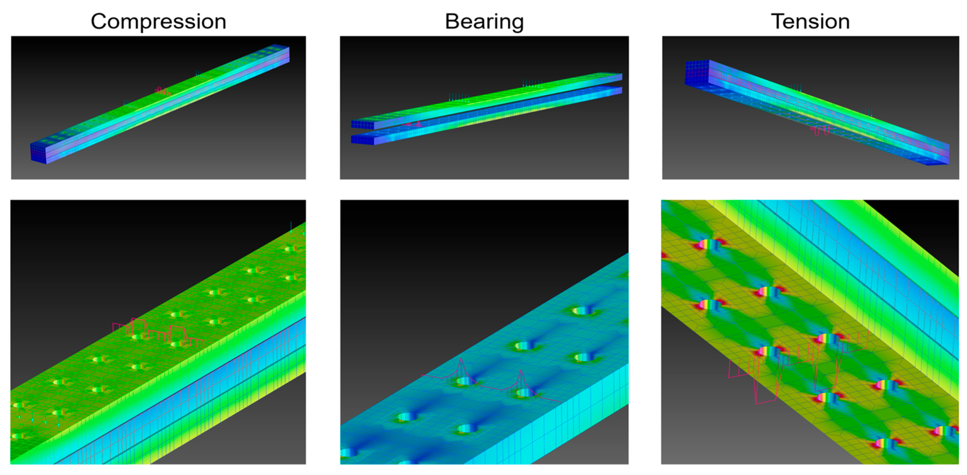
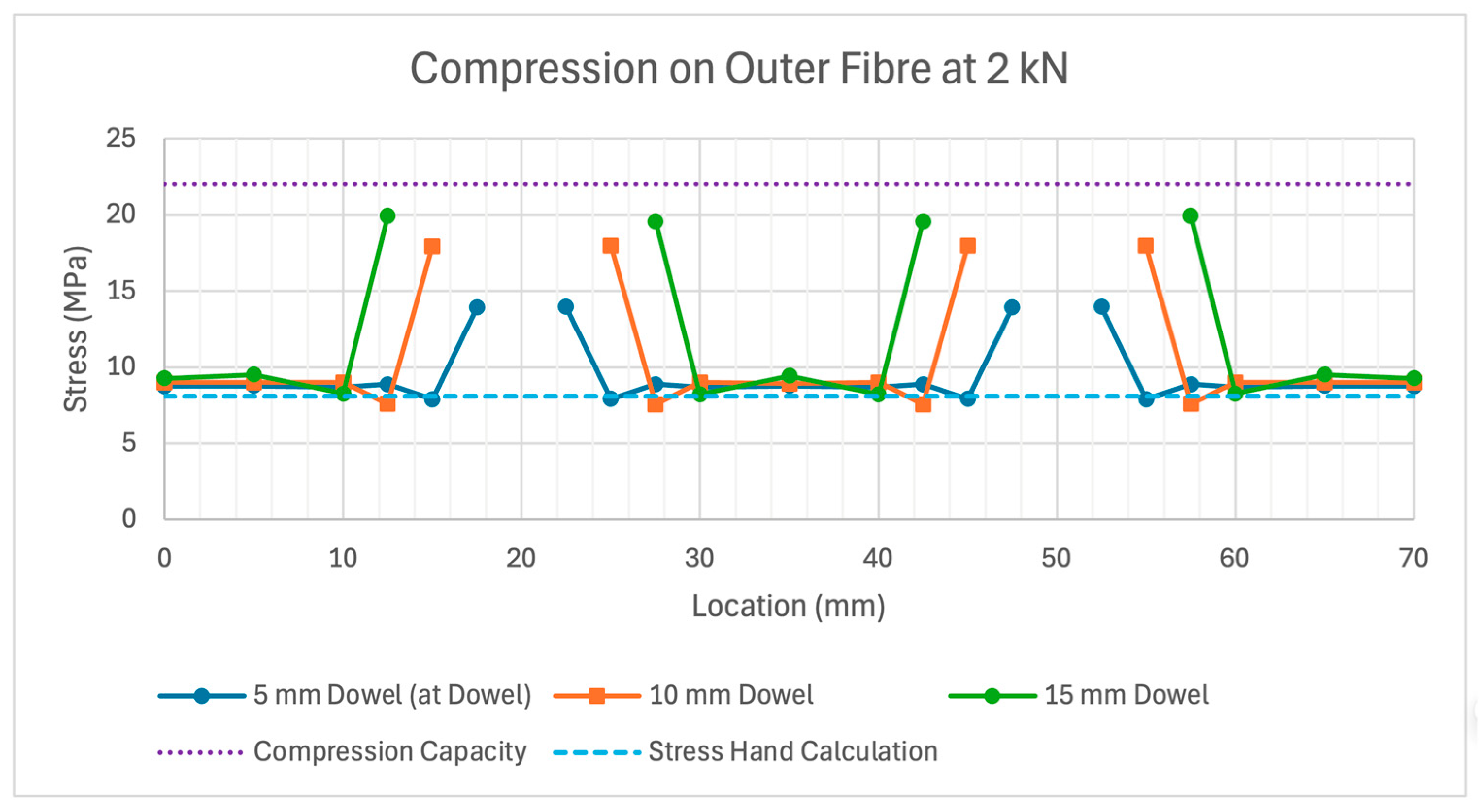
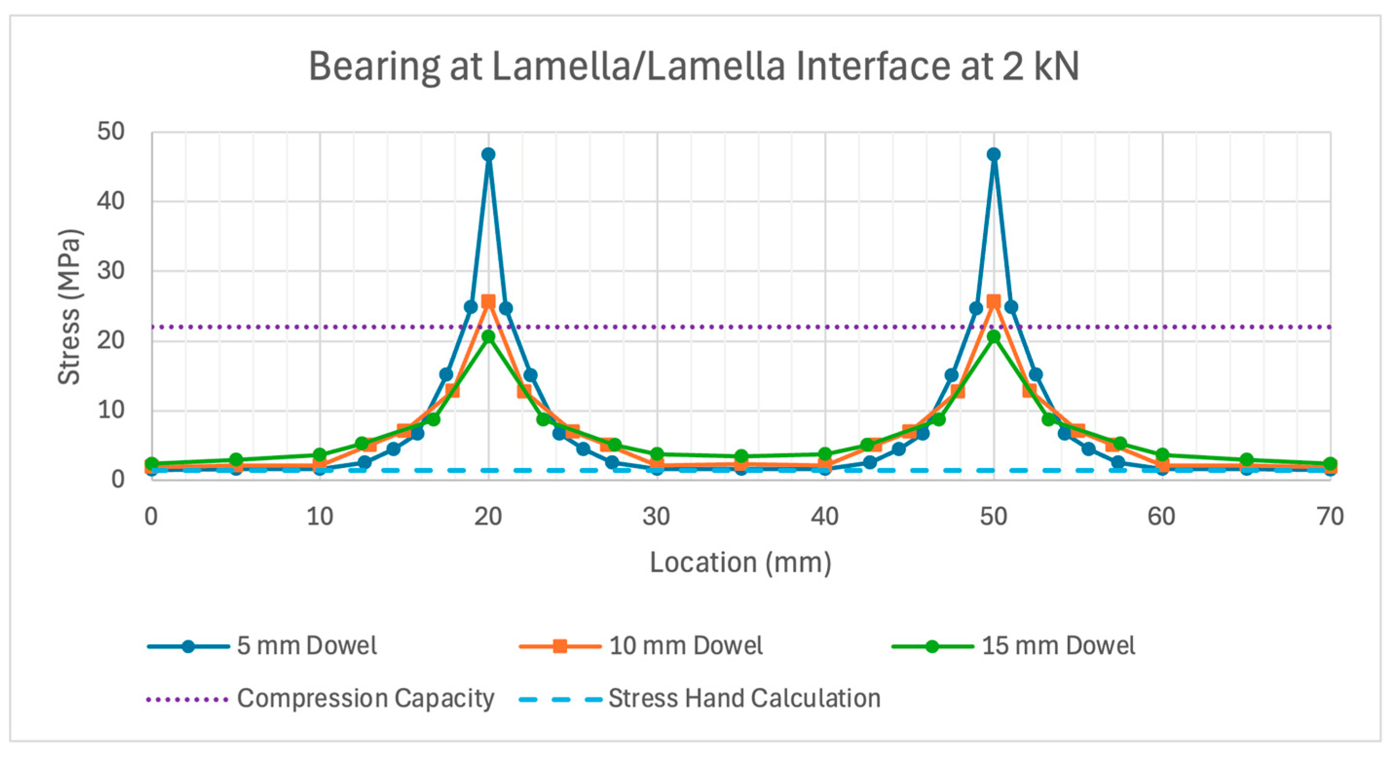
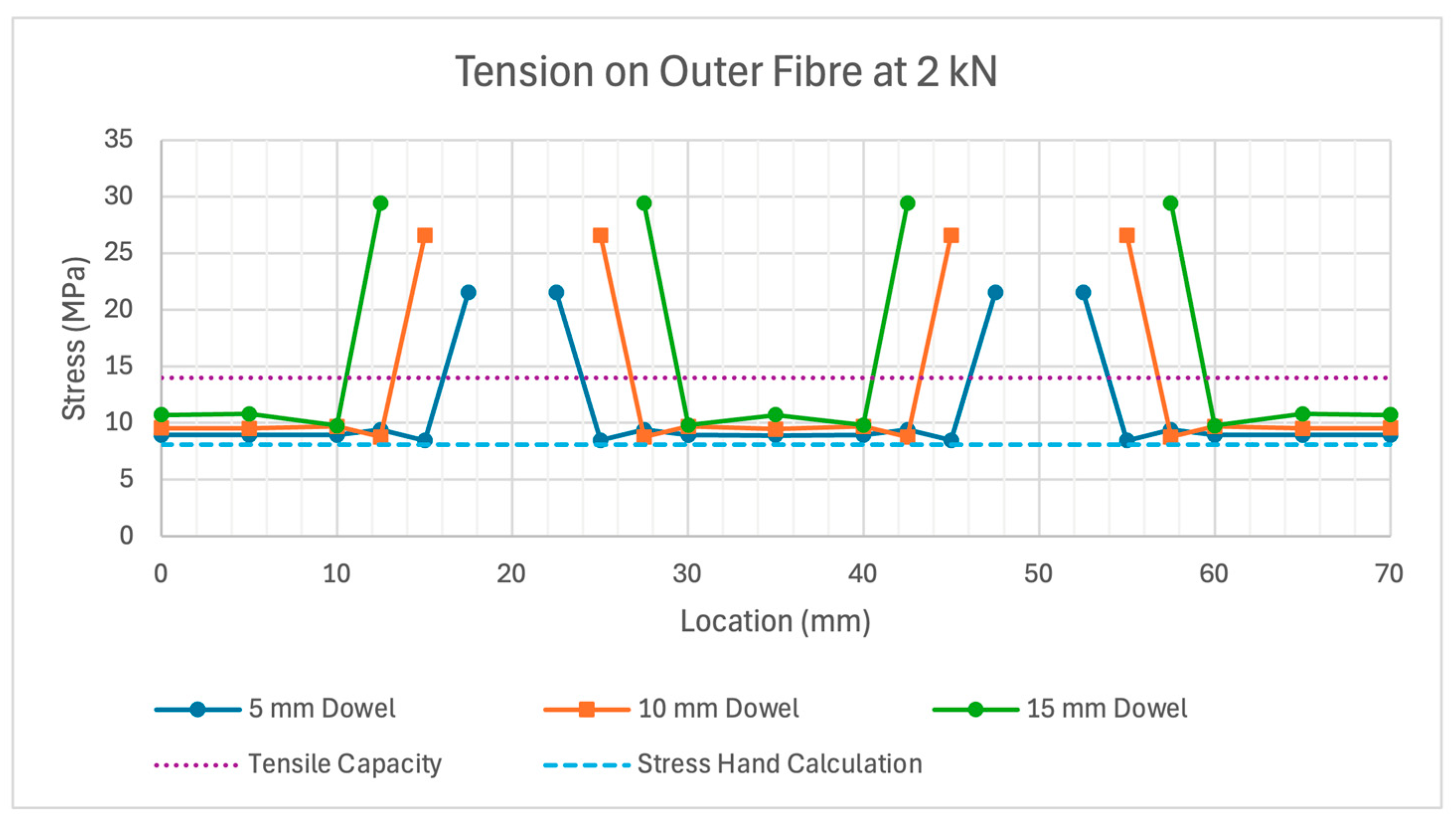
The effect of dowel diameter on global stiffness was explored with results shown in Figure 14. To investigate the local effects of dowels, three locations were investigated, as shown in Figure 15. Figure 16, Figure 17 and Figure 18 show the stress results for compressive outer fibre at midspan, bearing in shear zone, and tensile outer fibre at midspan, respectively. Also plotted are calculations predicting the average shear flow stress between lamella 1 and 2 and the axial stress at midspan.

3.4. Lamella Thickness

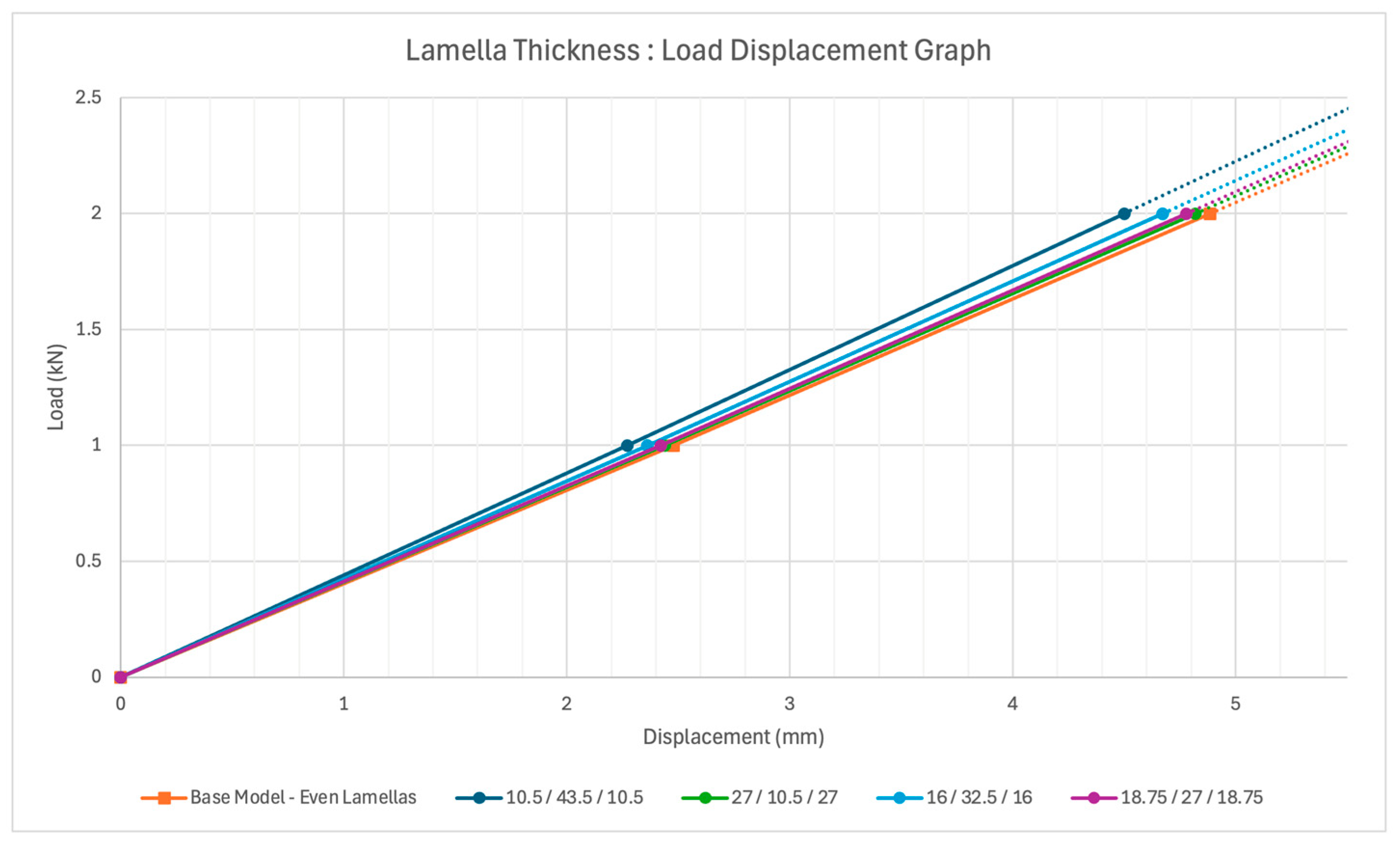
The alteration of lamella thickness within the section build-up was explored with results shown in Figure 19.

3.5. Wood Type

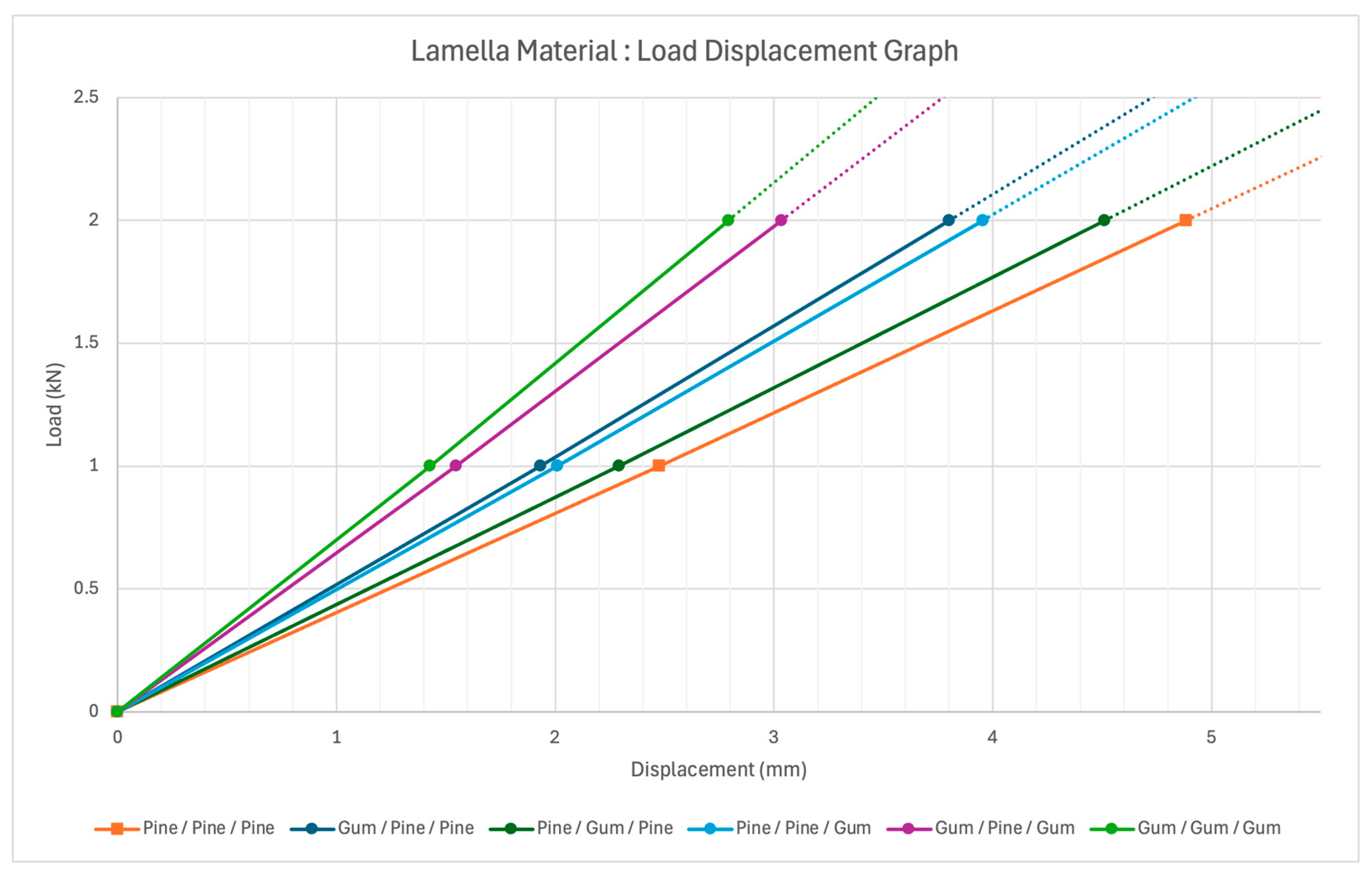
The wood-type for each lamella was varied to investigate the effect of spotted-gum on global stiffness, with results shown in Figure 20. Orthotropic properties used for the spotted-gum lamella are shown in Table 3.

3.6. Optimised Beam

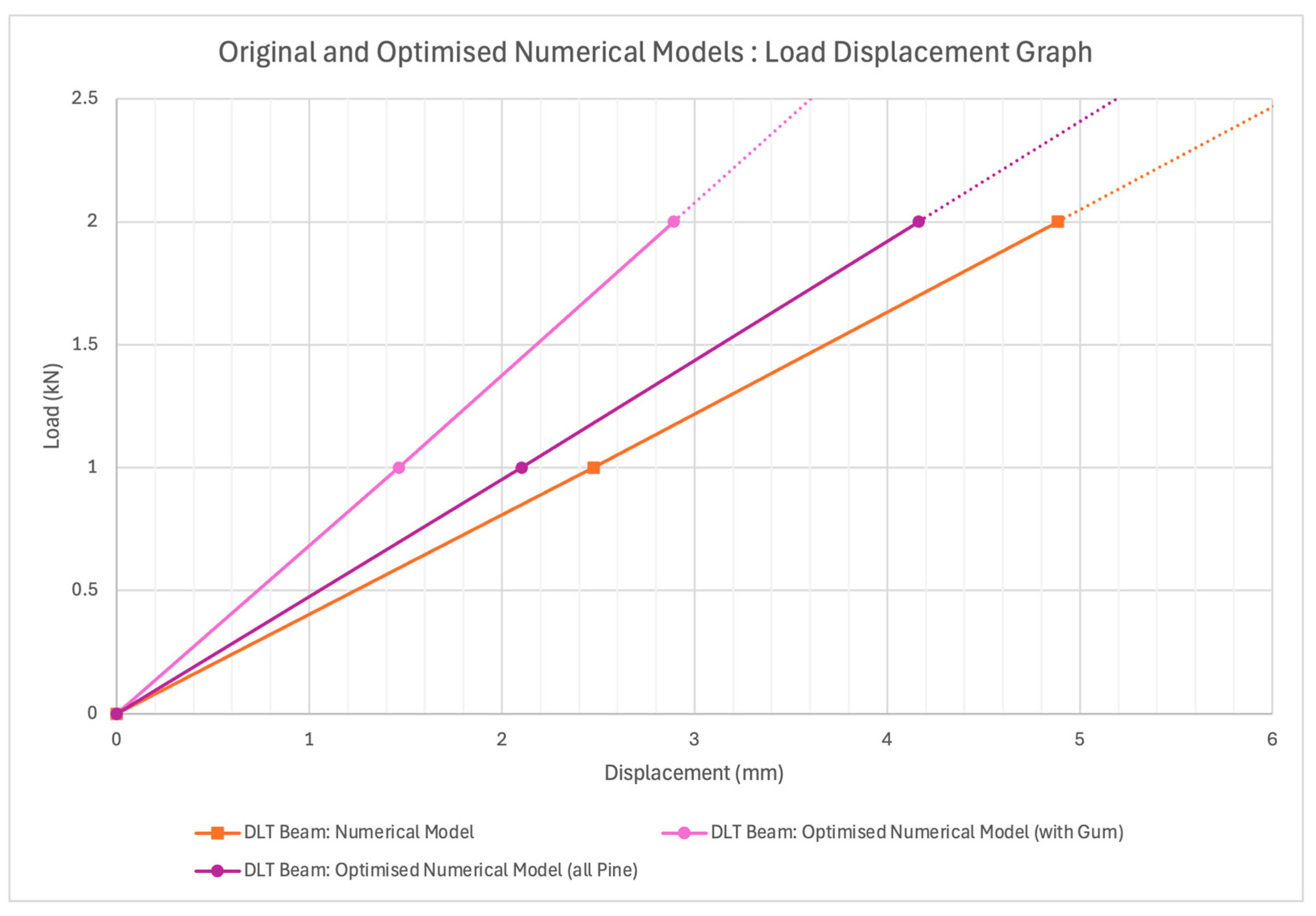
The insights from the parametric study were integrated into an optimised beam, with results shown in Figure 21. These included
  • Dowel Spacing: 50 mm → 40 mm.
  • Dowel Placement: Consistent Dowel Spacing → Reduced Dowels in Centre Zone.
  • Dowel Diameter: 10 mm → 10 mm.
  • Lamella Thickness: 21.5 mm/21.5 mm/21.5 mm → 10.5 mm/42.5 mm/10.5 mm.
  • Lamella Material: Pine/Pine/Pine → Gum/Pine/Gum.

3.7. XYZ Scaled 5 m Beam

A scaled 5 metre beam was modelled by scaling the original numerical model by 3.7 in each direction to obtain a 238 mm × 259 mm × 5000 mm beam.
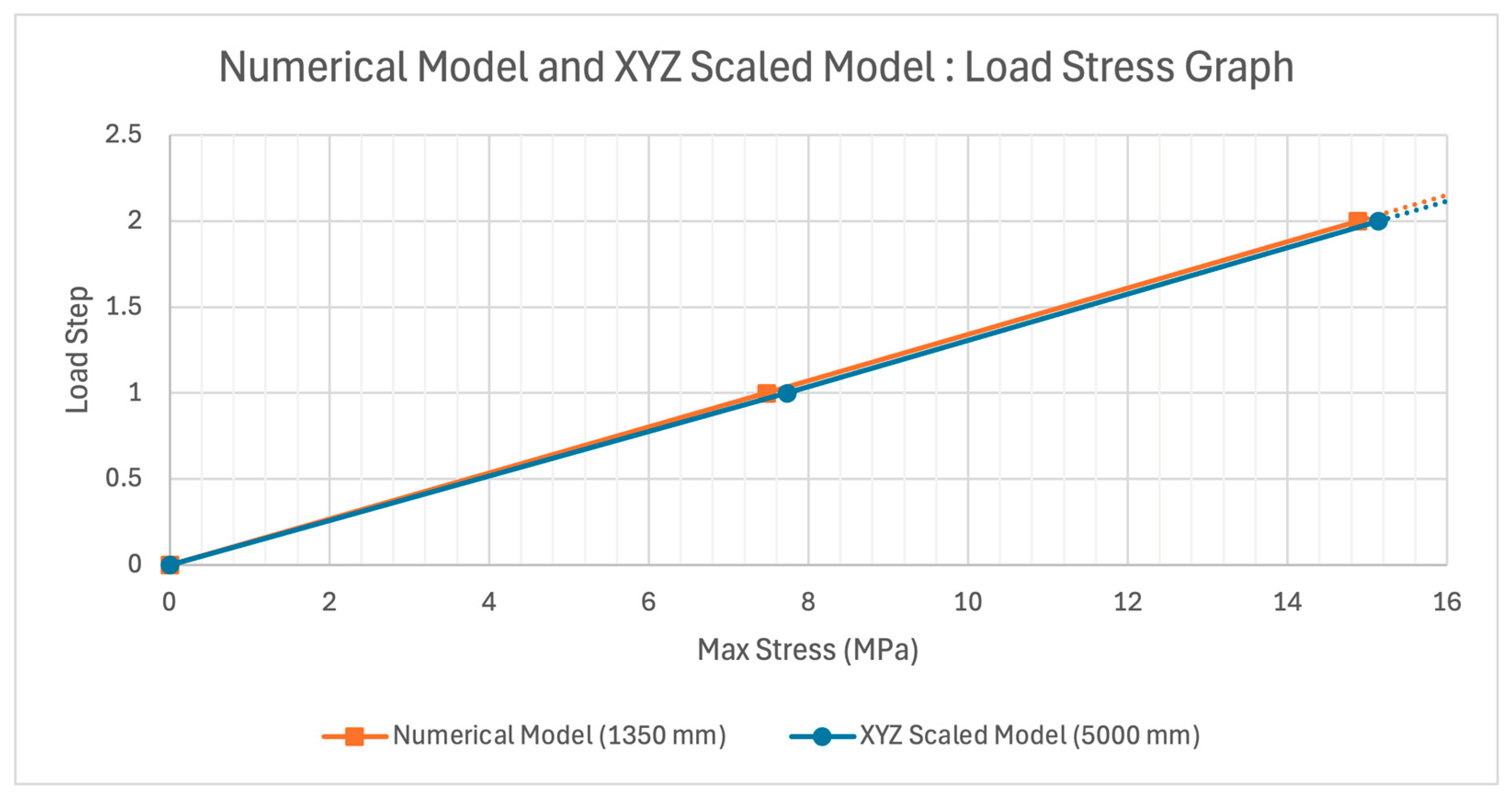
Figure 22 confirms that the scaled beam maintains elastic similarity with the original model. When geometrically similar beams share the same material and linear-elastic properties, their stress distributions remain unchanged with scale [34].

3.8. Dowel-Laminated Gum (DLG): An Optimised, Project-Scale DLT Beam Prototype

3.8.1. Material and Modelling Set-Up

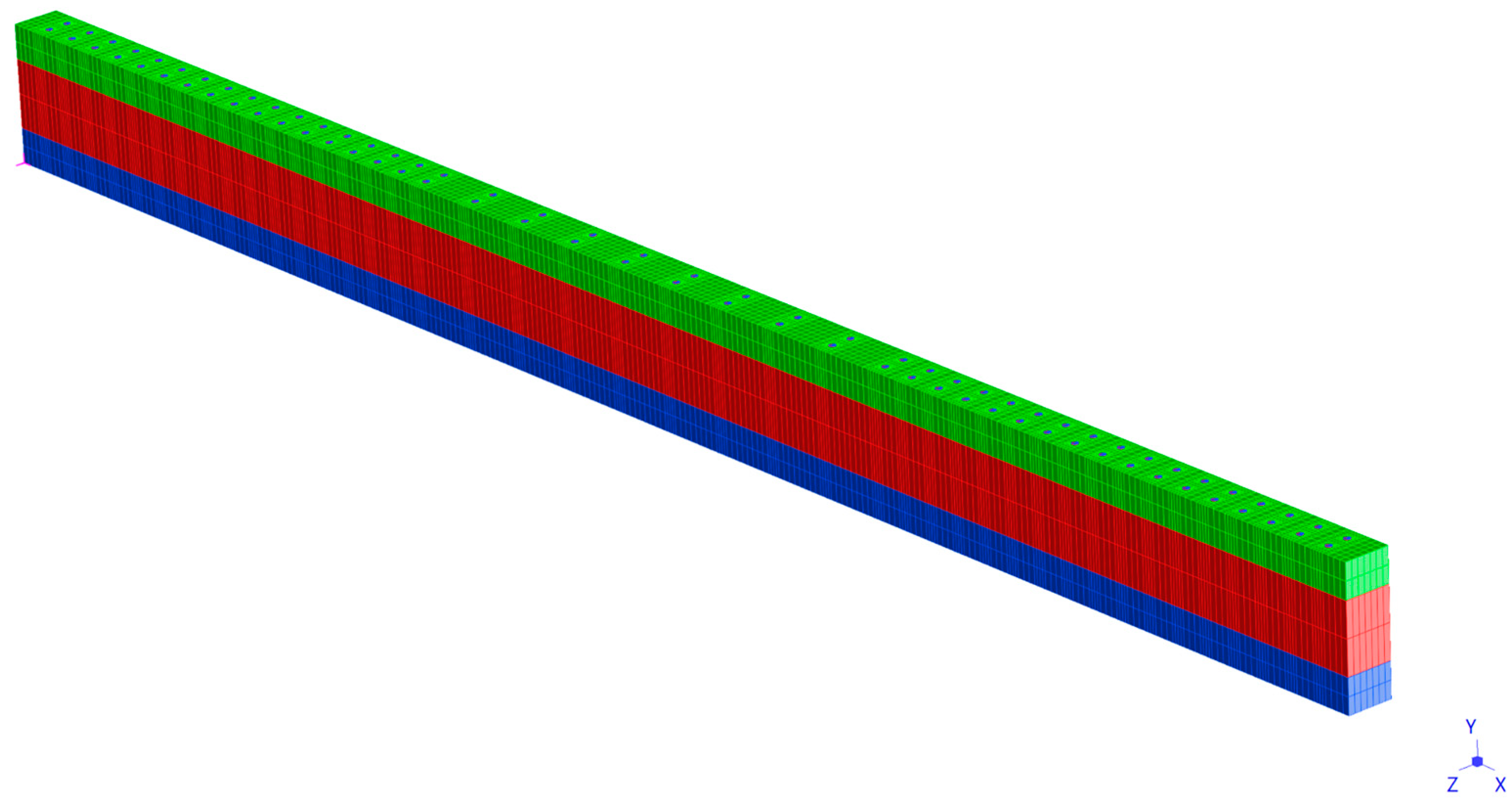
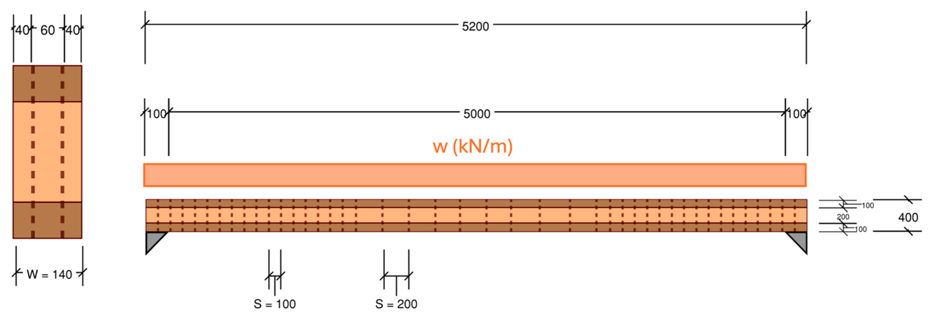
A project-scale beam prototype named Dowel-Laminated Gum (DLG) shown in Figure 23 and Figure 24 was developed using the optimisation insights from the parametric study. Geometric inputs for the beam are shown in Table 4 and Table 5. The beam was loaded with residential floors loads from AS1170.1 Structural Design Actions, Part 1: Permanent, imposed and other actions [23], shown in Table 6. The load combinations were obtained from AS1170.0-2002: Structural Design Actions, Part 0: General principles [22], shown in Table 7. The assumed tributary area was 5 metres by 5 metres to represent a low-rise residential application.
The geometry of the section geometry was a deep, thin section to replicate a realistic section size and improve flexural efficiency. The member bending strength was checked against AS1720.1 clause 3.2.1.1 [21]. The assumptions included a duration of peak action of 5 months, seasoned structural timber, full lateral restraint on the top lamella, and no temperature effects. A serviceability limit span/360 was chosen as a mid-range limit from the limits suggested in AS1170.0 Table C1.
The deflection results were scaled by the stiffness reduction factor calculated in Section 3.4 to calibrate the DLG results. The DLG beam was compared to the predicted deflection of an equivalent glulam beam of the same dimensions and lamella composition, calculated using the gamma Method. The loads were applied as a universally distributed load along the top of the beam, with plate supports at either end.
The design began by using a span-over-depth ratio of 12.5 to find the depth of 400 mm, and then assigning a realistic beam width of 140 mm. The optimisation insights from the parametric study were introduced. Note that the lamella thickness ratio of 16 mm/32 mm/16 mm was used to assign a realistic thickness to the central lamella.
  • Dowel Spacing and Placement: 40 mm (optimised model) × 3.7 (length scaling factor) = 148 mm → 100 mm spacing in high shear zone, 200 mm in low shear mid-span zone.
  • Dowel Diameter: 10 mm (optimised model) × 2 (width scaling factor) = 20 mm → 20 mm.
  • Lamella Thickness: 16 mm/32 mm/16 mm × 6.2 (depth scaling factor) = 99 mm/202 mm/99 mm → 100 mm/200 mm/100 mm.
  • Lamella material: Gum/Pine/Gum (optimised model) → Gum/Pine/Gum.

3.8.2. Deflection Results

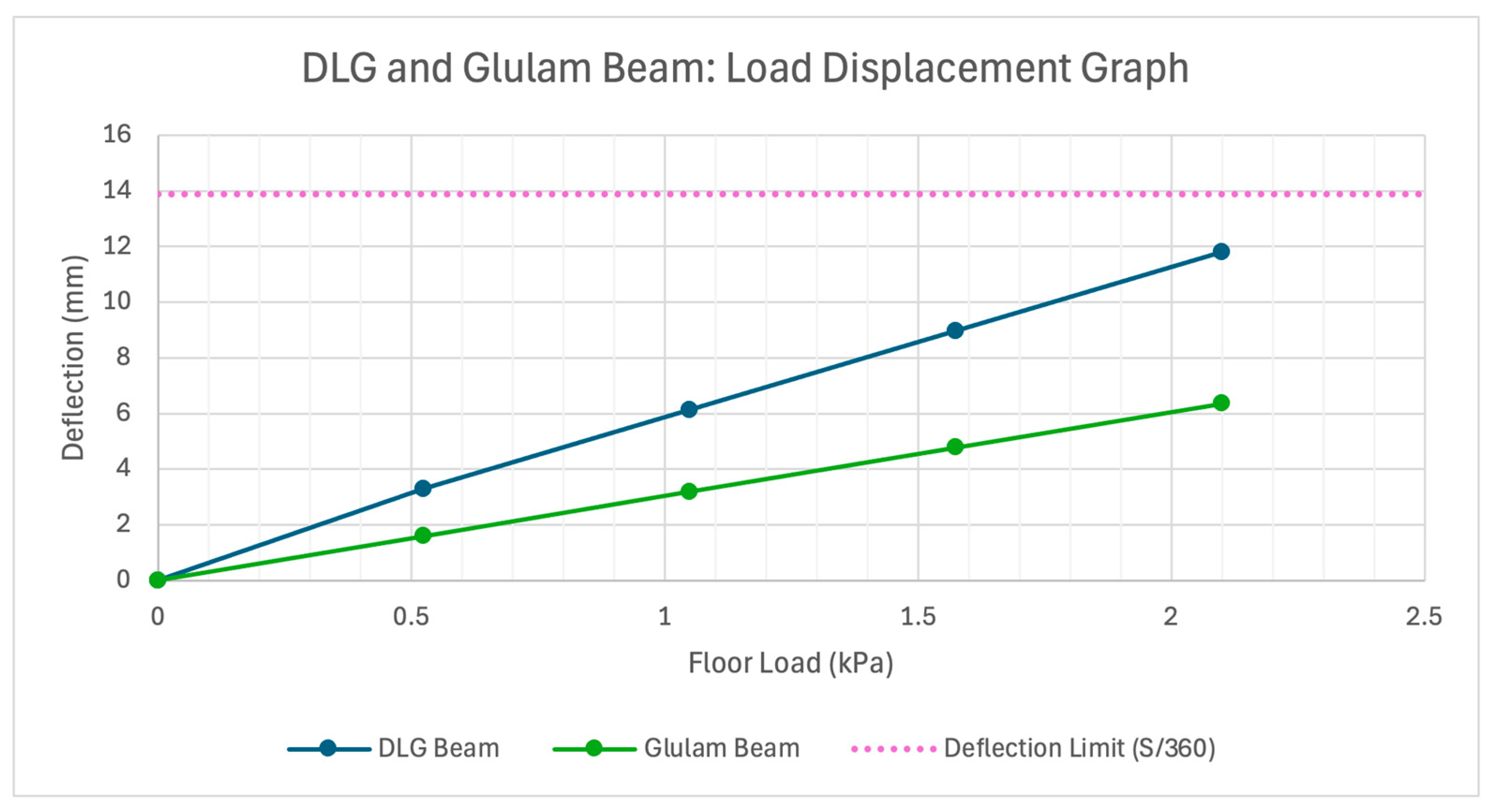
Deflection results for the DLG and glulam beams are shown in Figure 25.

3.8.3. Stress Results

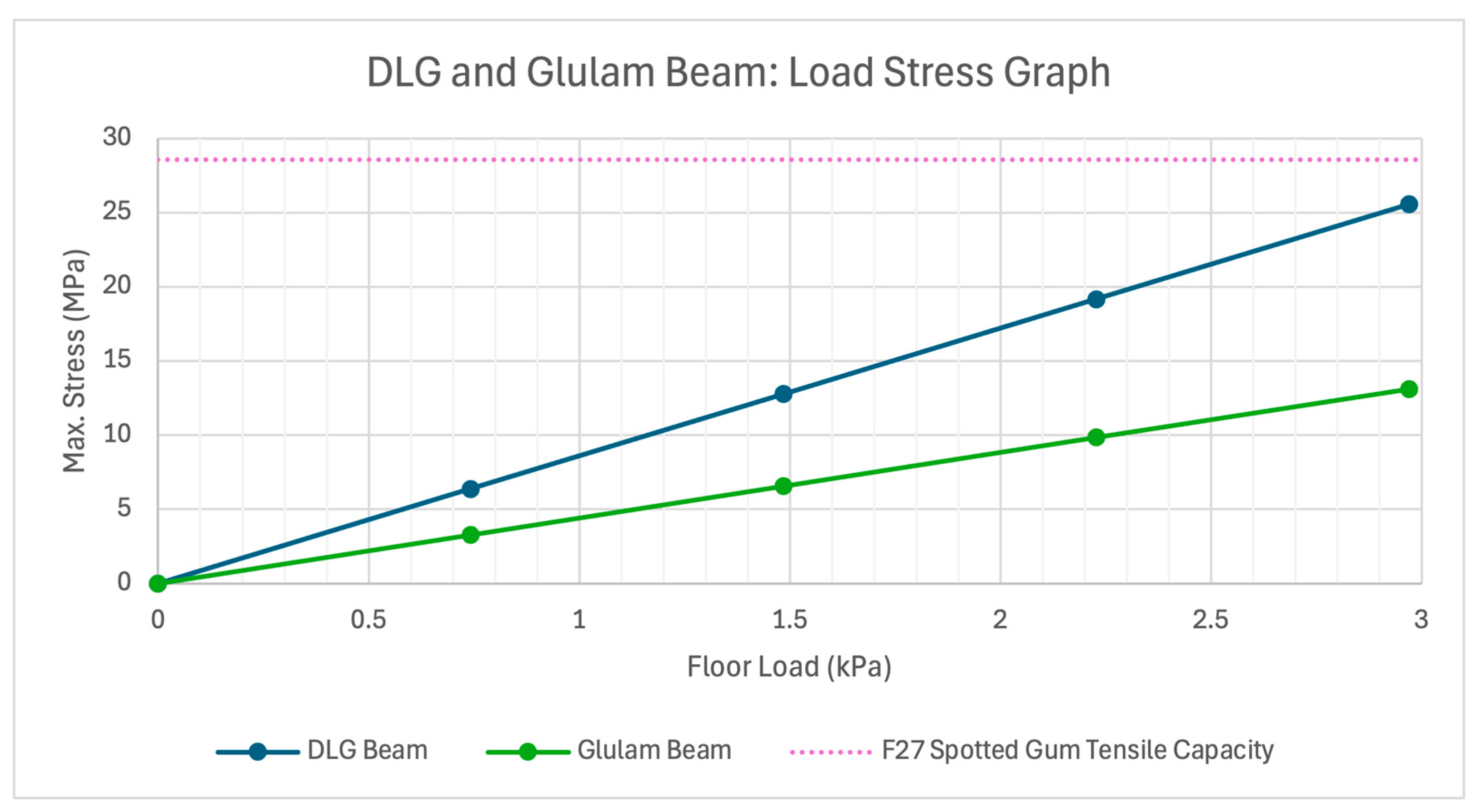
Stress results for the DLG and glulam beam are shown in Figure 26.

4. Discussion

4.1. Engineering Insights from Model Behaviour

The numerical results provide several insights into DLT structural behaviour. The first parametric study indicates DLT occupies a position between fully composite glulam and non-composite stacked timber. This is highlighted in Figure 11, where the DLT (Orange) sits between the glulam and solid beam (Purple/Pink), representing a fully composite/homogenous material, and the no-dowels beam (Blue), representing a non-composite material.
In terms of project-based structural design, a DLT beam can be checked against ultimate limit state (ULS) and serviceability limit state (SLS) criteria. For the SLS, geometric and material alterations can improve stiffness to comply with deflection limits. In this paper, a 14.7% reduction in deflection was made through the optimisation of dowel spacing, dowel diameter, lamella thickness, and dowel placement. Reduced dowel spacing from 50 mm to 40 mm in isolation reduced deflection by 4.4% and, similarly, alteration of lamella thicknesses from an even to a thicker centre (10.5 mm/42.5 mm/10.5 mm) reduced deflection by 7.9% at 2 kN. For dowel diameter, the optimal diameter of 10 mm had 6% less deflection than the lower bound of 15 mm and 0.6% less deflection than a 5 mm dowel. An intriguing observation in Figure 12 is the rate of stiffness benefit with dowel spacing alteration. While the 50 mm dowel spacing was stiffer than the 100 mm spacing by approximately 25%, double the number of dowels were used, suggesting a trade-off point between stiffness increase and practicality. The parametric study suggests an optimised geometric arrangement can be achieved for DLT beams to improve SLS compliance.
In terms of materials, the introduction of spotted gum had a clear impact on the global stiffness of the DLT beam, as shown in Figure 20. This is expected, due to spotted gum’s higher elastic modulus (19 GPa) relative to C24 Scots Pine (11 GPa). The optimal configuration was the Gum/Pine/Gum beam, which only had 8% more deflection than the fully hardwood beam, aligning with composite theory. When combined with the geometric improvements, the optimised beam with spotted gum outer lamellae had 41% less deflection than the original beam (Figure 21).
For the ULS, tensile rupture on the lower lamella and dowel embedment or bearing deformation are key design parameters to be checked. The parametric study showed that tensile stress at the outer fibre at midspan can be reduced by smaller diameter dowels, while bearing stresses in the shear zone can be reduced by larger dowels, as shown in Figure 15, Figure 16, Figure 17 and Figure 18. This inverse relationship could be managed by the alteration of dowel diameter across the beam, whereby larger dowels are concentrated in shear-dominant zones, and smaller dowels are concentrated in bending-dominant zones.
The effect of dowel location was investigated in Figure 13. In the midspan zone, tension can be seen building up in the lower lamella before dissipating near the dowels, as opposed to the constant stress in the top lamella. This is a consequence of the fixing method of the hardwood dowels; as they are dry-hammered in, they create discontinuity and leave less effective area available to take tension. Since dowels contribute predominantly to shear transfer, concentrating dowels near the supports (where shear demand is highest) and away from the midspan (where axial tension is highest) in simply supported arrangements is structurally efficient. Similar to the SLS, these conditions suggest geometric optimisation can improve ULS compliance.
For a four-point bending test, this is straightforward; however, for loading arrangements for beams in buildings a more nuanced process would be required. An example would be for a floor load in a low-rise residential building, where tensile rupture and bearing stresses would have to be checked for various live-load arrangements. The minimum number of dowels required for each zone could then be specified.
The optimisation insights from the parametric study were used to design a project-scaled beam prototype called DLG, imagined in a low-rise residential setting. Loading conditions were obtained from the relevant Australian Standards. For SLS, the DLG beam satisfied the span/360 serviceability criterion, with a midspan deflection of 11.4 mm. This value incorporates the scaled deflection obtained using the stiffness-reduction factor derived in Section 2.3.2. The equivalent glulam beam, designed using the gamma method, exhibited approximately twice the stiffness of the DLG beam.
For the ULS, the stress results presented in Figure 26 were within the capacity limits calculated in accordance with AS 1720.1, with a maximum stress of 26 MPa for the 1.2G + 1.5Q load combination. While the DLG beam achieved approximately half the stiffness of an equivalent glulam member and relied on a number of modelling assumptions, these results suggest that DLT beams may be structurally viable in an Australian context. The modelling methodology and parametric insights presented in this paper are not limited to the Australian context; however, the DLG ULS check is specific to the Australian regulatory environment. Researchers or practitioners in other regions seeking to perform a similar ULS check would need to substitute the relevant national loading standard, timber design code, and species’ characteristic values accordingly; for example, Eurocode 5 in the European context [16].
The gamma method and shear flow approach provide simplified analytical tools for estimating deflection and stress in partially composite beams, and their accuracy relative to the numerical model was explored in the dowel diameter study. For shear flow, the underestimation of stress concentrations shown in Figure 17 is expected, as the analytical method assumes homogeneous shear connection across the full width and length of the beam. While the hand calculations showed reasonable agreement for global bending stress predictions, the presence of localised stresses in the numerical model highlight the need for numerical modelling in DLT design.
The limitation of the linear-elastic model was highlighted in the investigation on dowel diameter at critical compression, tension, and bearing locations shown in Figure 15. In Figure 17, bearing capacity for the dowels is exceeded for the 5 mm dowel and marginally exceeded for the 10 mm dowel. This indicates the point at which a plastic response would be expected; however, the linear-elastic model does not capture this. As such, the numerical response of the lamellae remains linear. This is observed in Figure 7, where the experimental results begin to separate from the numerical results as the beams undergo plastic behaviour. Notwithstanding this limitation, timber members in engineering practice are typically designed to remain within the linear-elastic range under SLS and ULS conditions. Within this elastic range, the model demonstrated reasonable agreement with experimental results, suggesting that an analytically based model could serve as a practical and accessible design tool for engineers.

4.2. Suitable Applications for DLT in Structures

Despite its lower stiffness compared with glued products, DLT could be suitable in applications where serviceability is not critical or where other benefits such as sustainability or ductility are prioritised.
As discussed earlier, DLT suffers from local deformation at the dowel interfaces in the shear zones [8]. For smaller-span beams, where shear is a dominating factor, this presents an obstacle to DLT design. However, for longer spans, where bending becomes the dominating factor, DLT benefits from its composite behaviour as the lamellae contribute more substantially to bending resistance. In building applications, this could be applicable to roof beams, secondary girders, and lightly loaded long-span members where deflection limits are moderate and dead load is low.
DLT’s sustainability and aesthetic benefits support its application in temporary structures, where long-term deflection, creep, and moisture effects are less critical. In these contexts, serviceability limits and loading conditions can be less stringent [22,23], allowing for more efficient material use and lightweight design. The absence of adhesives also allows for disassembly, reuse, and recycling at the end of the structure’s life, aligning with circular construction principles [7]. Sotayo et al. [8] discussed the potential application of DLT in seismic zones, based on its ductile failure modes.

4.3. Opportunities for Future Research

Opportunities remain to further expand the body of research on DLT in both an Australian and global context.
Numerical modelling of DLT captures local stress concentrations around dowel locations that can exceed those obtainable through hand calculation. While the modelling procedure developed in this paper reproduces the characteristic partial-composite response of DLT within the linear-elastic range, capturing quantitative results beyond this region requires models that account for post-yield timber behaviour. As discussed in Section 2.3, Strand7 does not currently support the orthotropic properties and plastic behaviour of wood. Platforms such as Abaqus and LS-DYNA, which support user-defined models and dedicated timber material formulations, could be better suited for this purpose.
In terms of parametric study, a limitation of the present paper is the restricted number of parameters explored. Broadening the parametric framework to encompass additional variables such as dowel properties and interaction effects among parameters may yield further improvements in global stiffness. In addition, integrating AI-assisted optimisation methods could automate the exploration of parameter combinations and support the identification of efficient configurations.
Bio-based adhesives and wood welding represent further avenues for improving composite action and stiffness, both of which could be approximated numerically through spring elements in Strand7.
In the Australian context, the application of local hardwoods presents a significant opportunity both for structural performance and domestic timber-industry development. To bridge the gap, experimental testing of DLT beams incorporating Australian hardwoods as both lamellae and dowels would provide a proof of concept and establish the experimental base for future numerical studies. The publishing of material properties in experimental studies is essential to allow for complete model validation. The study on Australian hardwood dowels by Khan et al. (2025) [6], covering the mechanical behaviour of Tasmanian oak and eucalyptus grandis under axial and flexural loading, provides a dataset from which experimental and numerical studies could be developed.
The absence of DLT and hardwood dowel guidance in AS1720.1 represents a regulatory gap that is also seen in the Eurocode. Performance-based solutions for DLT developed to align with the National Construction Code would be necessary for industry adoption.


5. Conclusions

This paper investigated the structural performance of DLT with the objective of outlining a linear-elastic modelling procedure and identifying optimisation strategies. The model and insights were used to develop a prototype beam relevant to Australian practice.
Section 2 developed a linear-elastic numerical modelling methodology in Australian FEA software Strand7. The numerical model was validated within the linear-elastic load range of 0–2 kN for the purposes of the parametric study; however, it overestimated the average deflection of the experimental beams by 29% at 2 kN. Despite this, the model captured characteristic DLT behaviour exhibited in the Sotayo et al. [8], O’Ceallaigh et al. [9], and Xu et al. [5] studies, including interlaminar slip.
The parametric study in Section 3 investigated four parameters influencing DLT structural performance: dowel spacing, dowel diameter, lamella thickness, and lamella material. The results indicated that geometric changes including reduced dowel spacing and altered lamella thicknesses can improve global stiffness. Using a native Australian hardwood (spotted gum) in the outer lamellae produced the most substantial stiffness improvements. The parametric findings were synthesised into an optimised beam concept which achieved 14.7% less deflection than the baseline numerical model. When combined with spotted-gum outer lamellae, 41% less deflection was achieved. A project-scale beam prototype called DLG was designed with loading conditions defined by relevant Australian standards, adopting a 1.5 kPa live load applied over a 5-metre-by-5-metre tributary area and represented as an equivalent uniformly distributed load on the beam. The beam satisfied both SLS and ULS requirements, indicating the structural viability of a DLT beam in an Australian context.
In Section 4, DLT behaviour in the linear-elastic zone was investigated with reference to engineering design. Key behavioural insights included the influence of dowel diameter on the failure modes, and comment on the placement of dowels in the shear and bending zones.
A key limitation of the numerical model was its inability to capture the plastic deformation which characterises DLT failure modes, dowel embedment, and tensile rupture. Strand7 does not currently support orthotropic plasticity for timber in the modelling environment. Consequently, other finite-element platforms (e.g., ABAQUS) would be required to capture the full mechanical response of DLT.
In summary, this paper contributes to the international and Australian research base on DLT by addressing identified knowledge gaps in numerical modelling procedures and stiffness optimisation strategies. The outcomes provide a basis for continued experimental development and numerical model refinement. They also indicate DLT’s potential as an adhesive-free mass-timber system that can support more sustainable construction practices in Australia.

Author Contributions

Conceptualization, B.H., J.H. and F.T.; methodology, B.H., J.H., F.T., C.I. and A.P.; software, B.H., C.I., A.P. and F.T.; validation, B.H. and F.T.; formal analysis, B.H., J.H. and F.T.; investigation, B.H. and F.T.; resources, F.T. and K.S.; data curation, B.H.; writing—original draft preparation, B.H.; writing—review and editing, B.H., J.H., C.I., A.P., F.T. and K.S.; visualization, B.H. and F.T.; supervision, J.H. and F.T.; project administration, B.H., J.H., A.P., C.I., F.T. and K.S. All authors have read and agreed to the published version of the manuscript.

Funding

This research received no external funding.

Institutional Review Board Statement

Not applicable.

Informed Consent Statement

Not applicable.

Data Availability Statement

The original contributions presented in this study are included in the article. Further enquiries can be directed to the corresponding authors.

Acknowledgments

This paper was completed as an undergraduate honours thesis and forms part of a broader research programme within the University of Sydney School of Civil Engineering, investigating the application of mass-timber systems in Australia. The authors would like to thank the academic staff at the School of Civil Engineering for their support.

Conflicts of Interest

The authors declare no conflicts of interest.

Abbreviations

The following abbreviations are used in this manuscript:
DLTDowel-laminated timber
CLTCross-laminated timber
AFLTAdhesive-free laminated timber
FEFinite element
FEAFinite element analysis
DLGDowel-laminated gum

References

  1. Ren, H.; Bahrami, A.; Cehlin, M.; Wallhagen, M. Proposing new adhesive-free timber edge connections for cross-laminated timber panels: A step toward sustainable construction. Case Stud. Constr. Mater. 2024, 20, e02975. [Google Scholar] [CrossRef]
  2. Ren, H.; Bahrami, A.; Cehlin, M.; Wallhagen, M. Performance of innovative adhesive-free connections for glued-laminated timber under flexural load. Structures 2024, 70, 107904. [Google Scholar] [CrossRef]
  3. Puettmann, M.E.; Wilson, J.B. Life-cycle Analysis of Wood Products: Cradle-to-gate LCI of Residential Wood Building Materials. Wood Fiber Sci. 2005, 37, 18–29. [Google Scholar]
  4. Guan, Z.; Sotayo, A.; Oudjene, M.; El-Houjeyri, I.; Harte, A.; Mehra, S.; Haller, P.; Namari, S.; Makradi, A.; Belouettar, S.; et al. Development of Adhesive Free Engineered Wood Products—Towards Adhesive Free Timber Buildings. In Proceedings of the 2018 World Conference on Timber Engineering, Seoul, Republic of Korea, 20–23 August 2018. [Google Scholar]
  5. Xu, B.-H.; Zhang, S.-D.; Zhao, Y.-H.; Bouchaïr, A.; Zhang, B. Mechanical properties of adhesive-free cross-laminated timber. ASCE J. Struct. Eng. 2022, 148, 04022135. [Google Scholar] [CrossRef]
  6. Khan, I.U.; Subhani, M.; Ghabraie, K.; Ashraf, M. Exploring and refining testing approaches for hardwood dowels under axial and flexural loading: An experimental and numerical study. Wood Mater. Sci. Eng. 2025, 1–23. [Google Scholar] [CrossRef]
  7. Han, L.; Kutnar, A.; Sandak, J.; Šušteršič, I.; Sandberg, D. Adhesive-and Metal-Free Assembly Techniques for Prefabricated Multi-Layer Engineered Wood Products: A Review on Wooden Connectors. Forests 2023, 14, 311. [Google Scholar] [CrossRef]
  8. Sotayo, A.; Bradley, D.F.; Bather, M.; Oudjene, M.; El-Houjeyri, I.; Guan, Z. Development and structural behaviour of adhesive free laminated timber beams and cross laminated panels. Constr. Build. Mater. 2020, 259, 119821. [Google Scholar] [CrossRef]
  9. O’Ceallaigh, C.; Harte, A.M.; McGetrick, P. Numerical examination of the behaviour of dowel laminated timber elements utilising compressed wood dowels. In Proceedings of the World Conference on Timber Engineering, Oslo, Norway, 19–22 June 2023. [Google Scholar] [CrossRef]
  10. Archdaily. Woodcube/Architekturgentur. Available online: https://www.archdaily.com/421676/woodcube-architekturagentur (accessed on 8 September 2025).
  11. Thoma, E. Thoma Parts Catalogue System Holz100. 2012. Available online: https://www.thoma.at/cms/wp-content/uploads/2017/07/parts_catalog.pdf (accessed on 10 September 2025).
  12. Rombach Bauholz + Abbund Gmbh. NURHOLZ Flyer. 2025. Available online: https://www.nur-holz.com/de/service/downloads?acceptCookies=Necessary&cachebust=6a0e28ed3e991 (accessed on 10 September 2025).
  13. Yeh, Y.-H.; Yeh, Y.-C. Bending Behaviour and Failure Modes of Non-Glue-Laminated Timber Beams Composed of Wooden Dowels and Self-Tapping Screws. Buildings 2024, 14, 394. [Google Scholar] [CrossRef]
  14. Bouhala, L.; Fiorelli, D.; Makradi, A.; Belouettar, S.; Sotayo, A.; Bradley, D.F.; Guan, Z. Advanced numerical investigation on adhesive free timber structures. Compos. Struct. 2020, 246, 112389. [Google Scholar] [CrossRef]
  15. Bell, T.A. A Detailed Investigation into the Engineering Properties and Challenges Affecting the Potential Introduction of a UK Grown Dowel-Laminated Timber Floor Panel into the Domestic Construction Market. Ph.D. Thesis, University of Strathclyde, Glasgow, UK, 2018. [Google Scholar]
  16. EN 1995-1-1:2004; Eurocode 5: Design of Timber Structures—Part 1-1: General—Common Rules and Rules for Buildings. CEN: Brussels, Belgium, 2004.
  17. Forest and Wood Products Australia Limited. Mid-Rise Timber Building Structural Engineering; WoodSolutions Technical Design Guide 50; Forest and Wood Products Australia: Melbourne, Australia, 2023; pp. 66–74. [Google Scholar]
  18. Gorenc, B.E.; Tinyou, R. Steel Designers Handbook, 4th ed.; New South Wales University Press: Sydney, Australia, 1981. [Google Scholar]
  19. Zaman, A.; Chan, Y.-Q.; Jonescu, E.; Stewart, I. Critical challenges and potential for widespread adoption of mass timber construction in Australia- An analysis of industry perceptions. Buildings 2022, 12, 1405. [Google Scholar] [CrossRef]
  20. Leggate, W.; McGavin, R.L.; Outhwaite, A.; Gilbert, B.P.; Gunalan, S. Barriers to the Effective Adhesion of High-Density Hardwood Timbers for Glue-Laminated Beams in Australia. Forests 2022, 13, 1038. [Google Scholar] [CrossRef]
  21. AS 1720.1:2010; Timber Structures—Design Methods. Standard Australia: Sydney, Australia, 2010.
  22. AS 1170.0:2002; Structural Design Actions Part 0: General Principles. Standard Australia: Sydney, Australia, 2002.
  23. AS 1170.1:2002; Structural Design Actions—Part 1: Permanent, Imposed and Other Actions. Standard Australia: Sydney, Australia, 2002.
  24. Goetze, E. Planning Isn’t the Only Reason Australia Isn’t Adding Enough Homes, Builders Say. ABC News, 6 November 2025.
  25. Department of Climate Change, Energy, the Environment and Water. Net Zero. Available online: https://www.dcceew.gov.au/climate-change/emissions-reduction/net-zero (accessed on 15 November 2025).
  26. ABCB. Prefabricated, Modular and Offsite Construction Handbook; Australian Building Codes Board: Canberra, Australia, 2024.
  27. Infrastructure NSW. State Infrastructure Plan 2024–2025: A 5-Year Plan; Infrastructure NSW: Sydney, Australia, 2025.
  28. Strand7. About Us. Available online: https://www.strand7.com/html/Strand7PtyLtd.htm (accessed on 8 September 2025).
  29. Strand7 Pty Ltd. Materials. Available online: https://www.strand7.com/html/materials.htm (accessed on 8 September 2025).
  30. Strand7 Pty Ltd. Materials: Orthotropic. Available online: https://www.strand7.com/strand7r3help/Content/Topics/Materials/MaterialsOrthotropic.htm (accessed on 8 September 2025).
  31. EN 338; Structural Timber—Strength Classes. BSI Standards: London, UK, 2016.
  32. WoodSolutions. Gum, Spotted. Available online: www.woodsolutions.com.au/wood-species/hardwood/gum-spotted (accessed on 14 November 2025).
  33. Forest Products Laboratory. Wood Handbook—Wood as an Engineering Material; Forest Products Laboratory: Hanover, NH, USA, 2021.
  34. Ramu, M.; Raja, V.P.; Thyla, P.R. Establishment of structural similitude for elastic models and validation of scaling laws. KSCE J. Civ. Eng. 2013, 17, 139–144. [Google Scholar] [CrossRef]
Figure 1. Experimental set-up.
Applsci 16 05330 g001
Figure 2. Brick model, 3D perspective.
Applsci 16 05330 g002
Figure 3. Brick model, diagrammatic detail.
Applsci 16 05330 g003
Figure 4. Brick model, stress and deflection for 2 kN.
Applsci 16 05330 g004
Figure 5. Brick model section, local stresses and interlaminar slip at 2 kN.
Applsci 16 05330 g005
Figure 6. Numerical model, stress profile at midspan.
Applsci 16 05330 g006
Figure 7. Numerical model and Sotayo et al.’s [8] load displacement graph to 8 kN.
Applsci 16 05330 g007
Figure 8. Numerical model and Sotayo et al.’s [8] load displacement graph to 2 kN.
Applsci 16 05330 g008
Figure 9. Solid-beam numerical model, 3D stress perspective for 2 kN.
Applsci 16 05330 g009
Figure 10. No-dowel numerical model, 3D stress perspective for 2 kN.
Applsci 16 05330 g010
Figure 11. Solid beam, glulam [8], no-dowel, DLT [8], load displacement graph.
Applsci 16 05330 g011
Figure 12. Dowel spacing, load displacement graph.
Applsci 16 05330 g012
Figure 13. Bending moment and shear force diagram (not to scale) overlayed on stress beam section for 2 kN.
Applsci 16 05330 g013
Figure 14. Dowel diameter, load displacement graph.
Applsci 16 05330 g014
Figure 15. Strand7 stress study key (not to scale).
Applsci 16 05330 g015
Figure 16. Compression stresses on outer fibre at midspan.
Applsci 16 05330 g016
Figure 17. Bearing stresses in shear zone.
Applsci 16 05330 g017
Figure 18. Tensile stresses in outer fibre at midspan.
Applsci 16 05330 g018
Figure 19. Lamella thickness, load displacement graph.
Applsci 16 05330 g019
Figure 20. Wood type, load displacement graph.
Applsci 16 05330 g020
Figure 21. Original and optimised numerical models, load displacement graph.
Applsci 16 05330 g021
Figure 22. Original and scaled beam, load stress graph.
Applsci 16 05330 g022
Figure 23. DLG numerical model, 3D perspective.
Applsci 16 05330 g023
Figure 24. DLG beam, diagram.
Applsci 16 05330 g024
Figure 25. DLG and glulam-beam deflection results (factored).
Applsci 16 05330 g025
Figure 26. DLG and glulam-beam results (factored).
Applsci 16 05330 g026
Table 1. Sotayo et al. AFLT Beam 1 geometric and material properties [8].
Beam# of SamplesLamellae (Width × Depth × Length) (mm)Number of LamellaeLamellae SpeciesDowel SpeciesDowel Diameter (mm)Dowel Spacing (mm)
AFLTB1570 × 21.5 × 13503Scots PineCompressed Scots Pine1050
Table 2. Available material properties for beam components from Sotayo et al. and those used as substitutes.
ComponentWood TypeMean Modulus of Elasticity Parallel (E Long)Mean Modulus of Elasticity Perpendicular (E Perp)Mean Shear Modulus G Mean DensitySource
LamellaC24 Scots Pine 11,000 MPa370 MPa690 MPa420 kg/m3EN338 Table 1 [31]
DowelC24 Scots Pine Compressed25,000 MPaN/A1568.2 MPa1300 kg/m3EN338 Table 1 [31], Sotayo et al. 2020 [8]
Table 3. Spotted-gum material property inputs.
Model ComponentWood TypeMean Modulus of Elasticity Parallel E LongEstimated Mean Modulus of Elasticity Perpendicular Estimated Mean Shear Modulus GMean Density
LamellaF27 Spotted gum19,000 MPa2232.5 MPa1190.67 MPa990 kg/m3
Table 4. DLG beam, geometric inputs.
SpanTotal LengthDepthLamella ThicknessesLamella MaterialWidth
5000 mm5200 mm400 mm100 mm/200 mm/100 mmF27 Spotted Gum/C24 Scots Pine/F27 Spotted Gum140 mm
Table 5. DLG beam, dowel set-up.
Dowel DiameterDowel ColumnsDowel SpacingDowel Material
20 mm2100 mm in shear zone, 200 mm in midspan zoneCompressed Scots Pine
Table 6. DLG beam loads for AS1170.0:2002 and AS1170.1:2002.
LabelLoad
GDead Load of Beam + 0.5 kPa Flooring
Q1.5 kPa Residential Floor Load
Table 7. DLG beam load combinations for AS1170.0:2002 and AS1170.1:2002.
CheckLoad Combination
SLSG + Q
ULS1.2G + 1.5Q
Disclaimer/Publisher’s Note: The statements, opinions and data contained in all publications are solely those of the individual author(s) and contributor(s) and not of MDPI and/or the editor(s). MDPI and/or the editor(s) disclaim responsibility for any injury to people or property resulting from any ideas, methods, instructions or products referred to in the content.