Abstract
The article focuses on floor composite beams used in buildings. Within the scope of the conducted analytical and numerical studies, the authors compared the typical solution—namely, the T-shaped reinforced concrete beam—with various types of composite beams, the height of which could not exceed the predetermined usable depth of the beam cross-section. The analyses focused on traditional steel–concrete composite beams, which are widely used in civil engineering, as well as modern solutions, such as timber–timber and steel–timber composite beams. A new type of a steel–timber composite beam with a cold-formed girder made of two channels was presented in this study. Due to the flexibility of the connections, the timber–timber and steel–timber composite beams were examined under three different connection conditions: full composite action, partial composite action, and no composite action (friction only). Composite beams with timber slabs are consistent with the principles of sustainable construction, which makes their comparison with conventional solutions particularly relevant. The load-deflection curves and the bending resistance of the analysed elements were obtained using numerical simulations. In the numerical analyses, advanced material models were used. Composite beams with timber elements had lower stiffness than the steel–concrete composite beam. For this reason, meeting the serviceability limit state can be more challenging for such structures. Furthermore, the degree of shear connection in the composite beams with timber elements had a strong impact on their load-bearing capacity and end-slip. The steel–timber composite beam with a cold-formed girder had the most favourable resistance-to-mass ratio. The analytical results, and especially the numerical findings, provide a foundation for future experimental investigations.
1. Introduction
Concrete, steel, timber, and steel–concrete composite beams are well known solutions in civil engineering. General rules for designing these elements are presented in multiple standards. The production of steel and concrete causes significant CO2 emissions. However, the use of timber elements, instead of structural elements made of steel and concrete, can help reduce such emissions. Winchester and Reilly demonstrated that the intensity of CO2 in timber production is under 25% of that of cement and under 50% of that of steel [1]. The increase in the use of timber structures and new solutions with timber elements could help reduce greenhouse gas emissions [2]. The growing availability of engineered wood products has led to an increased use of timber and the development of innovative structural solutions. Timber is a renewable, easy to produce material with low density [3]. Engineering wood products and, in particular, laminated veneer lumber (LVL) and cross-laminated timber (CLT), are characterised by a lower number of defects than solid timber. LVL beams can have service holes and notches [4]. Beams made of engineering wood products can be strengthened using pre-stressed bars [5] and carbon fibre reinforced polymer sheets and laminates [6]. One of the new solutions using engineering wood products is a timber–timber composite beam. Chiniforush et al. investigated timber–timber composite beams with cross-laminated timber (CLT) slabs and laminated veneer lumber (LVL) girders [7]. The authors analysed the load carrying capacity and stiffness of the beams and observed the failure mode, i.e., the brittle tension failure at the bottom fibre of the laminated veneer lumber girders. They also studied the impact of shear connection type. Single and double threaded screws, coach screws, screws in cementitious grout, and glued-in dowels were analysed in push-out tests. Bedon et al. investigated the structural performance of shear connections with inclined self-tapping screws in numerical simulations [8]. They noticed that both the properties of timber and the interface damage contacts in the region of connectors had a crucial impact on the numerical analysis. Timber slabs made of engineering wood products are also used in metal–timber composite beams. The girders of these composite elements are made of aluminium [9] or steel [10,11]. They can be extruded [9], welded [12], cold-formed [13], and hot-rolled [14]. Different cross-sections are used in the girders, e.g., I-sections [15], channels [16], rectangular tubes [17], and U-shaped cross-sections [18]. Many types of connections for metal–timber composite beams have been investigated, i.e., bolts [19], screws [20,21], bolts in grout pockets [22,23], hybrid-anchored screws [24], screws with nail plates [25], and screws with epoxy adhesive [26]. In the numerical models, the connections can be modelled as discrete connectors or as mesh-dependent connectors. Hassanieh et al. developed 3D finite element models of steel–timber composite connections with coach screws and bolts meshed with solid elements [27]. Zero length springs with a seven-parameter load-slip model were used as connectors in a steel–timber composite beam with an LVL slab [28]. Connectors modelled as wires of an axial connection type were used by Chybiński and Polus in the numerical model of an aluminium–timber composite beam [9]. A non-linear load-slip response for one connector was implemented into the model. In the case of aluminium–timber composite beams with partial shear connections, zero-length translator-type connectors and a trilinear load-slip curve were used [29]. Romero et al. used mesh-independent connectors to join an LVL slab with a steel beam [30]. The slot type was used for translational behaviour, while the align type was used for rotational behaviour. Due to the use of these connections, the slip along the longitudinal direction of composite beams was possible. A multilinear load-slip curve was used to describe the mechanical behaviour of the connectors. In the numerical models of metal–timber composite beams, timber slabs were modelled using different solutions. Hassanieh et al. and Chybiński and Polus used an orthotropic material and the failure of LVL was captured using the Hashin damage model [28,29]. Romero et al. adopted a bilinear stress–strain curve in compression and a linear relationship in tension [30]. Chybiński and Polus used a uniaxial elastic–plastic model to capture the LVL behaviour [9]. The authors assumed that the load-bearing capacity of the aluminium–timber composite beam was reached when stress in LVL exceeded tensile resistance.
Recently, steel–timber composite beams with thin-walled girders have been developed. These girders are characterised by a low weight. The use of lightweight thin-walled members can reduce material and assembly costs. Kyvelou et al. developed a steel–timber composite floor with particle boards and cold-formed steel beams [31,32]. Loss and Davison used omega-shaped and U-shaped girders in innovative steel–timber floors [18]. Navaratnam et al. conducted a numerical analysis of a steel–timber composite beam with a channel girder [16]. They demonstrated that the bending resistance of the composite beam (92.27 kNm) was 8.86 times higher than the one of a cold-formed girder (10.41 kNm). This solution may find application in modular construction, characterised by reduced cost [33].
The literature review revealed that past studies on timber–timber and steel–timber composite beams did not compare their structural behaviour, both with each other and with other systems such as concrete or steel–concrete composite beams. Within the framework of the conducted analytical and numerical investigations, the authors undertook a comparative study of floor composite beam solutions. The reference system was the traditional T-shaped reinforced concrete beam, which remains the most common and well-established solution in residential construction [34]. This benchmark was evaluated against the various types of composite beams, which fulfilled the requirement of not exceeding their assumed overall usable depth with their cross-sectional height. The study also encompassed conventional steel–concrete composite beams, which are extensively applied in engineering practice due to their favourable strength and stiffness characteristics [35,36], as well as novel composite alternatives such as timber–timber [37] and steel–timber [38] composite beams. The latter solutions are of particular interest in the context of sustainable construction, since they enable the increased use of renewable materials and reduce the environmental footprint. Both steel and timber beams can be connected with timber slabs. Composite action can result into multiple benefits. Composite beams have higher load-bearing capacity and stiffness than their individual girders prior to connection. Furthermore, slabs limit the possibility of lateral–torsional buckling of girders. On the other hand, composite beams need shear connections. For this reason, these solutions are more labour-intensive than non-composite beams. The literature presents applications of steel–timber composite elements. A steel–timber composite bridge with a post-tensioned laminated timber deck, welded plate steel girders, and steel cross-frames was built in 1993 [39]. Steel–timber composite beams with CLT slabs and hot-rolled girders were used in a student residence hall [40].
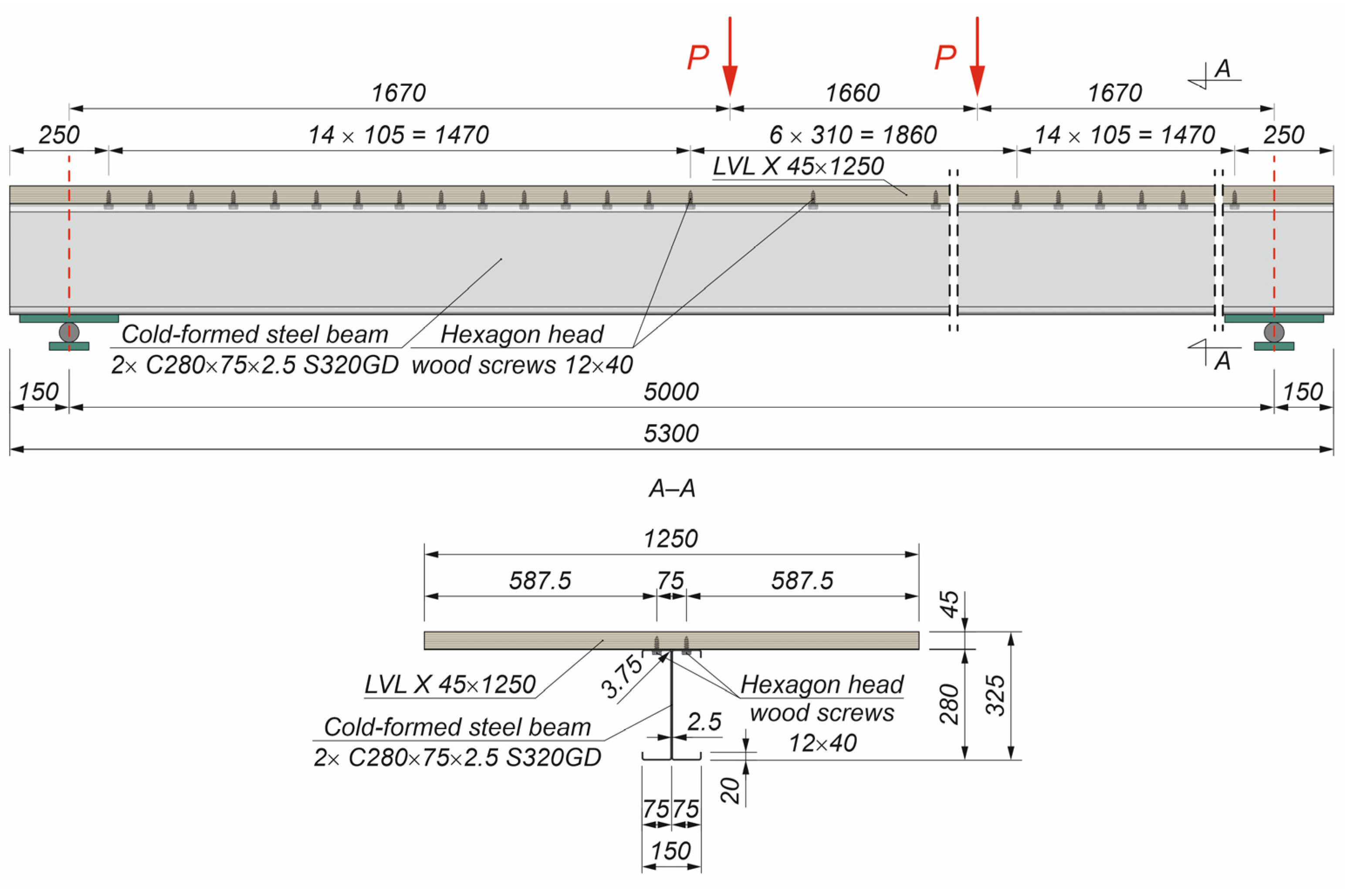
A new steel–timber composite beam with a cold-formed girder was developed in this study. The novelty was the use of two cold-formed channels connected in the shape of an I-beam as a composite beam girder. This solution offers several advantages, including the following: lightness, efficient use of materials, demountability, and possibility of use in modular structures. The steel–timber composite beams with cold-formed girders can be used in floor systems. Cold-formed girders of class 4 are exposed to local buckling. However, the neutral axis can be located in the slabs of simply supported composite beams, thus limiting the possibility of local buckling. However, steel–timber composite beams with cold-formed channels also have disadvantages. Their fire resistance is relatively low due to the low fire resistance of their thin-walled girders. However, the fire resistance of the composite beams can be increased by covering cold-formed girders with the timber components [41]. Furthermore, local yielding can occur at the beam supports. Loss and Davison used welded stiffeners to reinforced U-beam edges [18]. The analysed U-beams had a 4 mm section thickness. Cold-formed girders can have thickness lower than 3 mm. Welding is not recommended for thin-walled girders. However, additional support elements and bolted connections can be applied at the supports of steel–timber composite beams with cold-formed girders. Last but not least, screw connections are flexible. For this reason, the impact of slipping on the stiffness and load-bearing capacity of steel–timber composite beams with screwed connections should be taken into account.
The key focus of the analyses was to investigate how connector behaviour affected the global response of the composite beams. Because the load transfer mechanisms between the constituent materials are governed by the stiffness and deformability of the connectors, the timber–timber and steel–timber beams were examined under three connection scenarios: (i) full composite action, representing an idealised rigid connection; (ii) partial composite action, simulating realistic semi-rigid behaviour of connectors; and (iii) no composite action, where the materials interact solely through frictional contact. This approach enabled the identification of the structural advantages and limitations associated with each connection type and provided insight into their potential applicability in practice.
This paragraph ends Section 1, in which the literature review and the goals of the paper are formulated. In Section 2, the materials and methods used in the study are presented. In particular, the analysed beams and their finite element models are described. The results of the numerical simulations are presented in Section 3 and discussed in Section 4. In Section 5, the main conclusions of the paper and the limitations of the investigations are discussed.
2. Materials and Methods
2.1. Analysed Beams
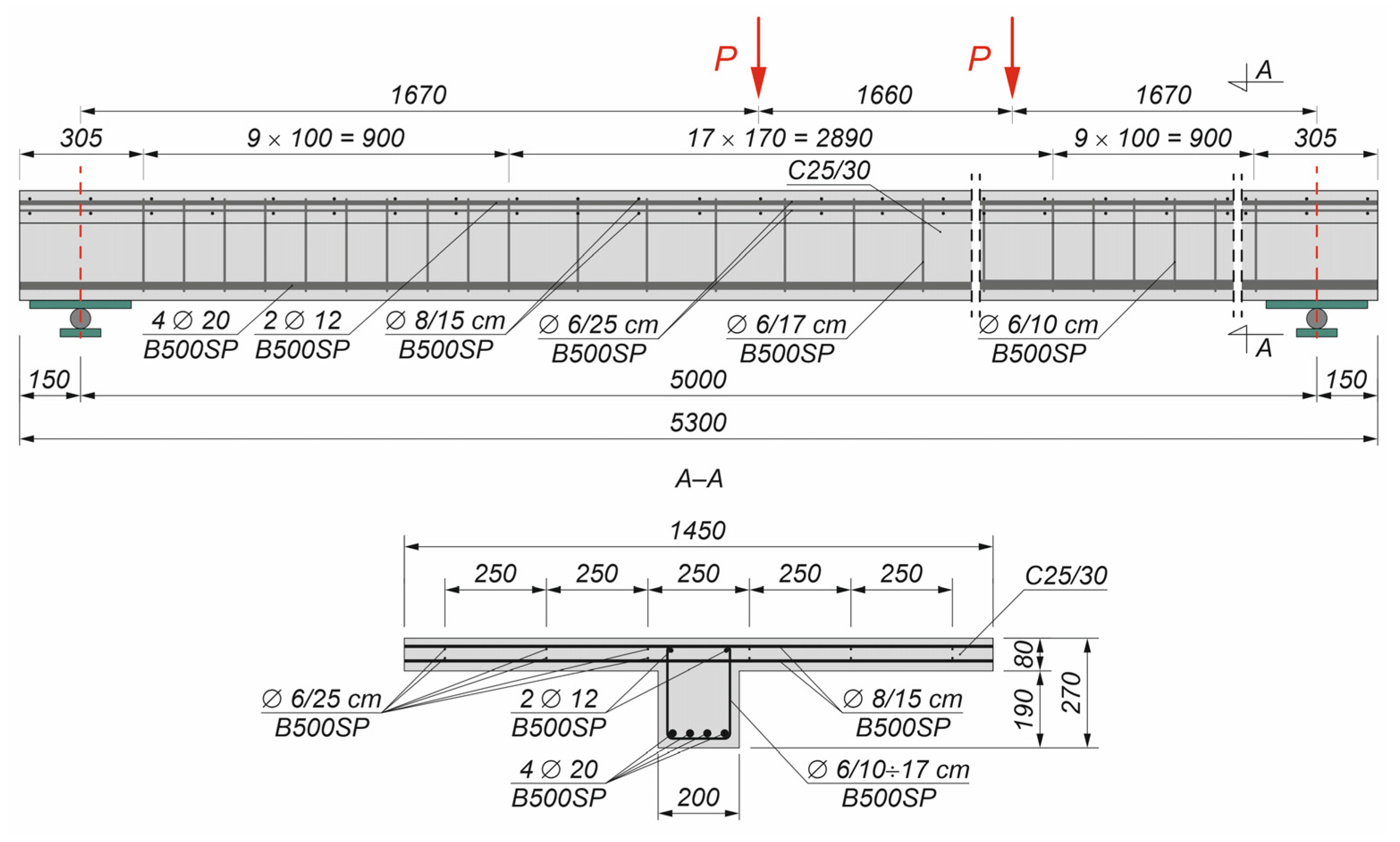
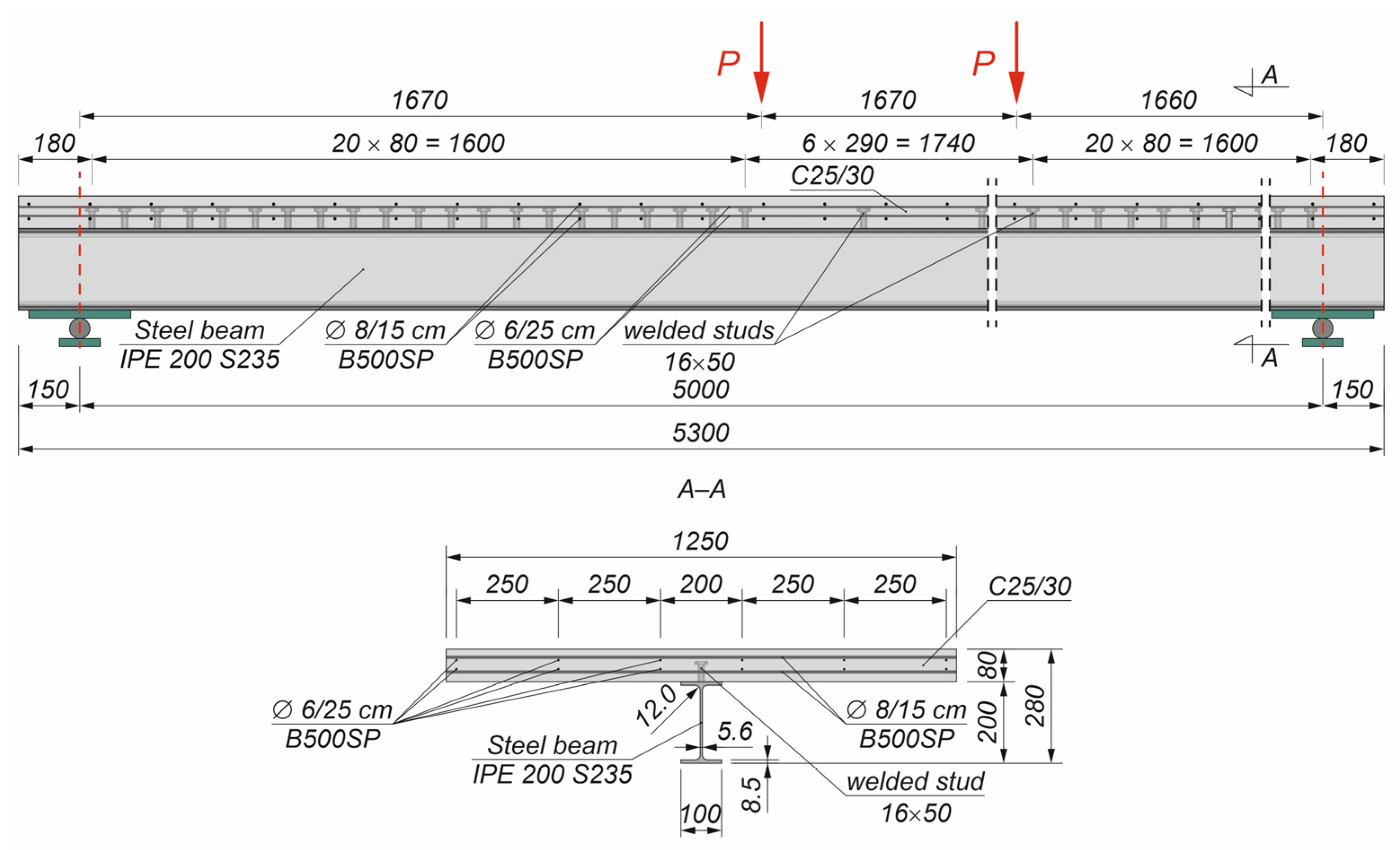
Figure 1 and Figure 2 present the geometry of the floor beam configurations analysed in this study, namely the conventional solutions of a T-shaped reinforced concrete beam and a steel–concrete composite beam, respectively. Both systems were selected as reference cases, as they are widely adopted in traditional residential construction and thus provide a meaningful baseline for comparative analyses with alternative composite beam arrangements.
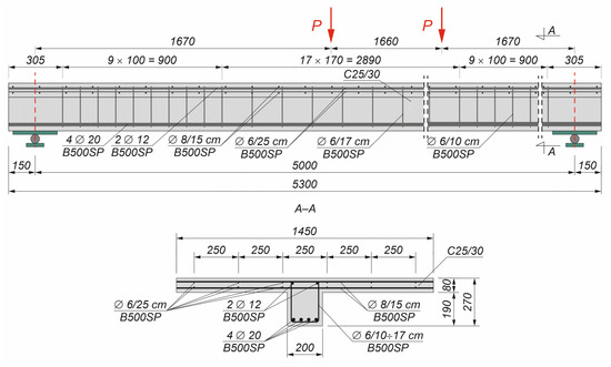
Figure 1.
Reinforced concrete T-beam (∅—rebar diameter).
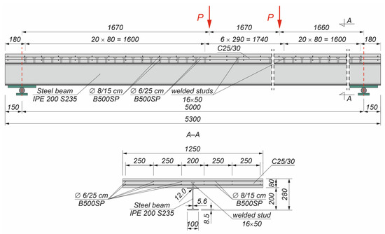
Figure 2.
Steel–concrete composite beam (∅—rebar diameter).
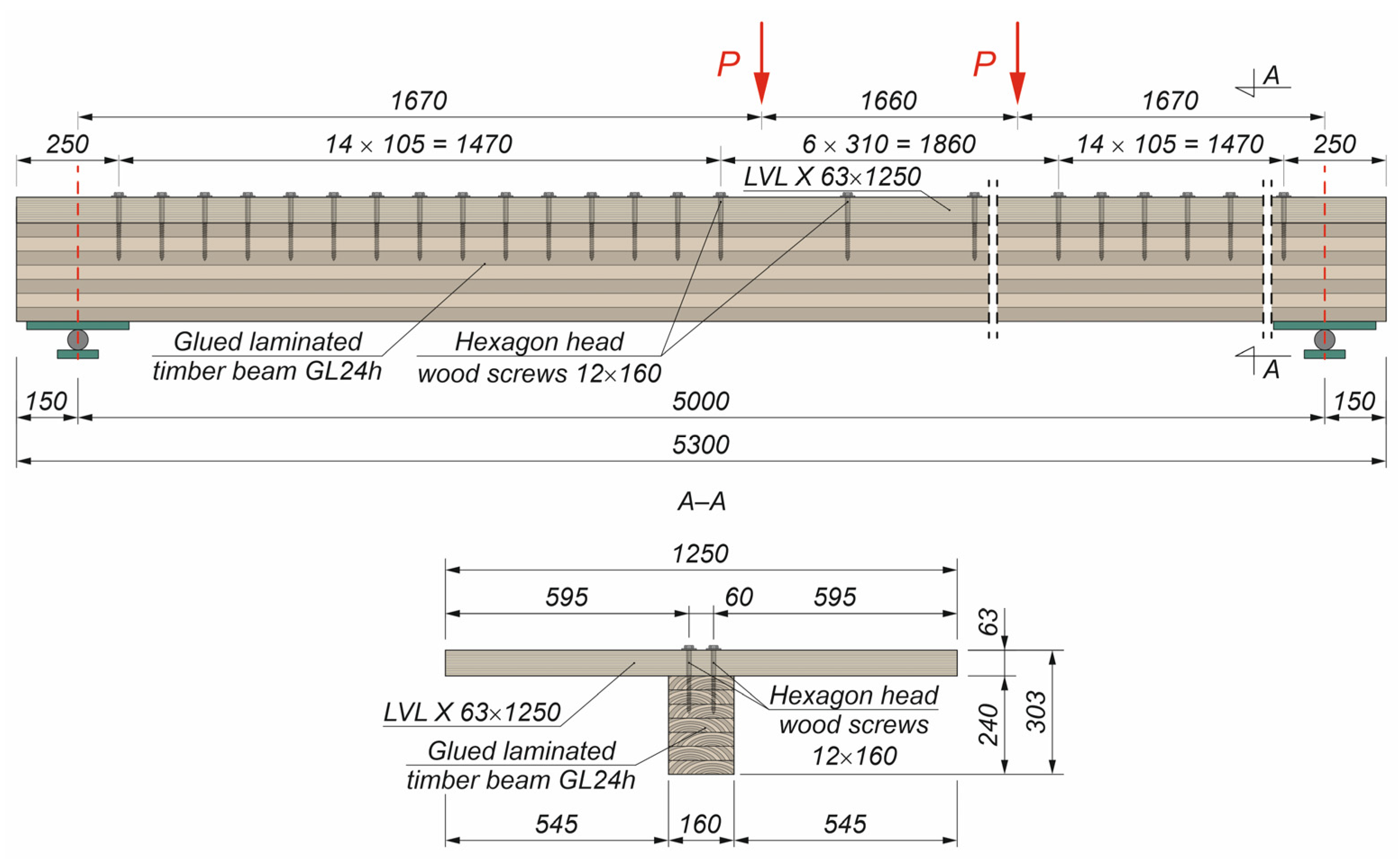
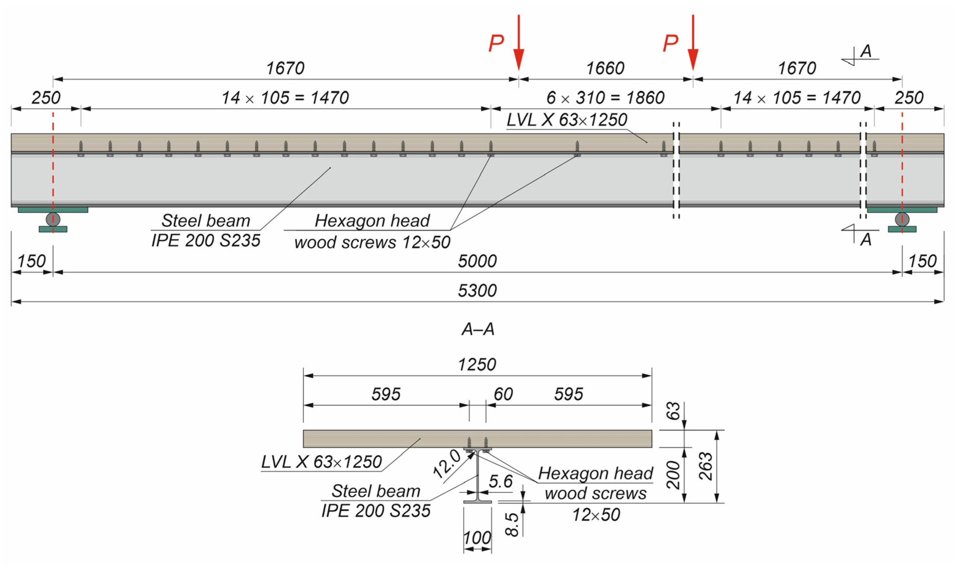
Figure 3, Figure 4 and Figure 5 present the novel beam configurations investigated in this study, namely the timber–timber composite beam, the steel–timber composite beam with a cold-formed girder, and the steel–timber composite beam with a hot-rolled girder, respectively. In each case, the illustrations correspond to the variant with partial shear connections, representing the semi-rigid interaction between the connected materials. These beams were designed as partially composite beams. The number of screws was insufficient to ensure full composite action. Furthermore, their screw connections were flexible, so the slipping had an impact on their stiffness and ultimate load.
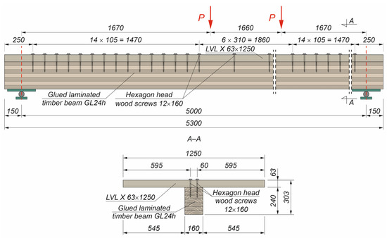
Figure 3.
Timber–timber composite beam with partial shear connections.
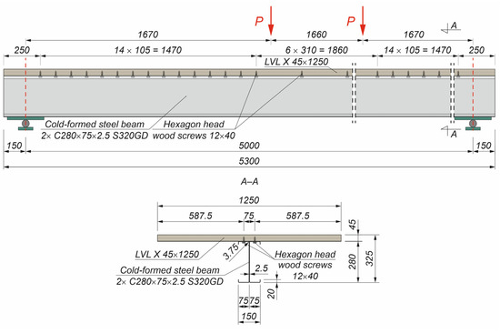
Figure 4.
Steel–timber composite beam with a cold-formed girder and partial shear connections.
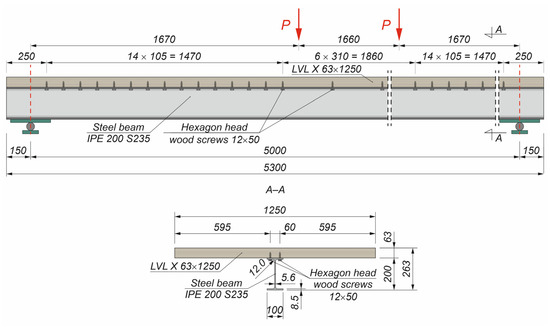
Figure 5.
Steel–timber composite beam with a hot-rolled girder and partial shear connections.
Table 1 summarises all the variants of the composite beams analysed in this study, together with the corresponding acronyms assigned to each configuration. The following assumptions were made to select the beam cross-sections: the bending resistance of the concrete beam and the composite beams with full shear connections was in the range from 140 to 150 kNm, and the construction height of the analysed elements was between 260 and 330 mm. The beams were simply supported and subjected to four-point bending. The beam span was 5 m. The distance between the loading points was 1.66 m.

Table 1.
Concrete T-beam and composite beams analysed in this paper.
The bending resistance of the reinforced concrete T-beam (142.3 kNm) was calculated based on Eurocode 2 [42], while that of the composite beams with full shear connections (Table 2) was based on Eurocode 4 [43]. The effective width of the concrete flange in the T-beam (1.45 m based on [42]) was greater than the effective width of the composite beam slab (1.25 m calculated from [43]). In the case of the elastic resistance to bending of the composite beams, the ideal cross-sections were obtained using the modular ratio. The plastic resistance to bending of the composite beams was calculated using the rectangular stress block method.

Table 2.
The bending resistance of the composite beams with full shear connections.
2.2. Numerical Models
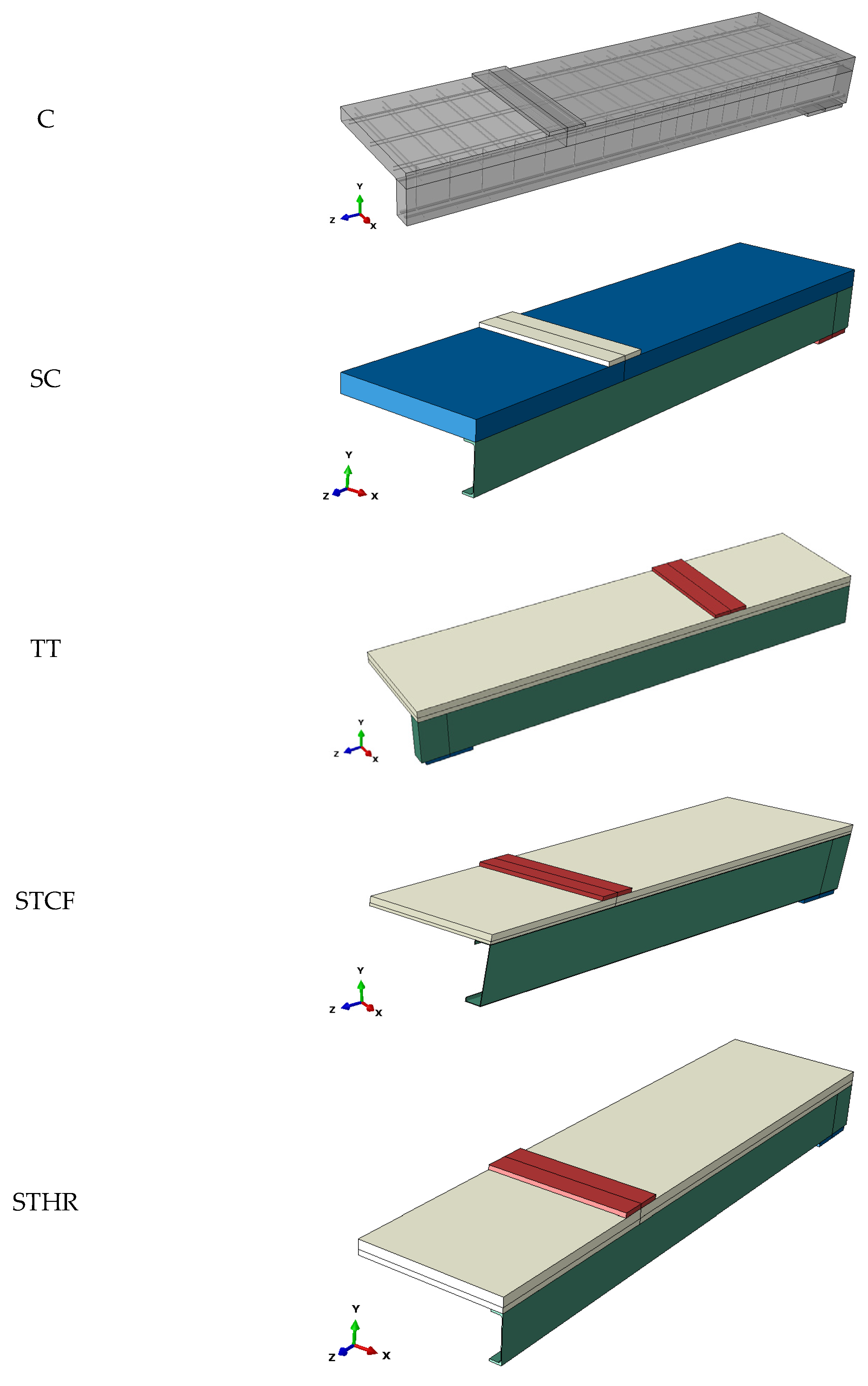
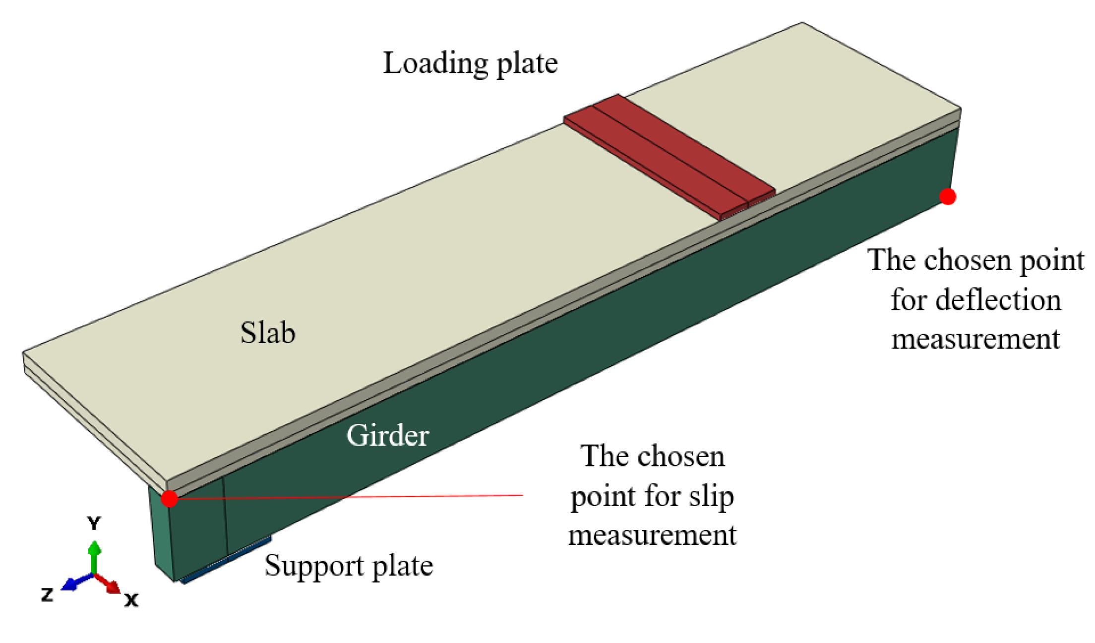
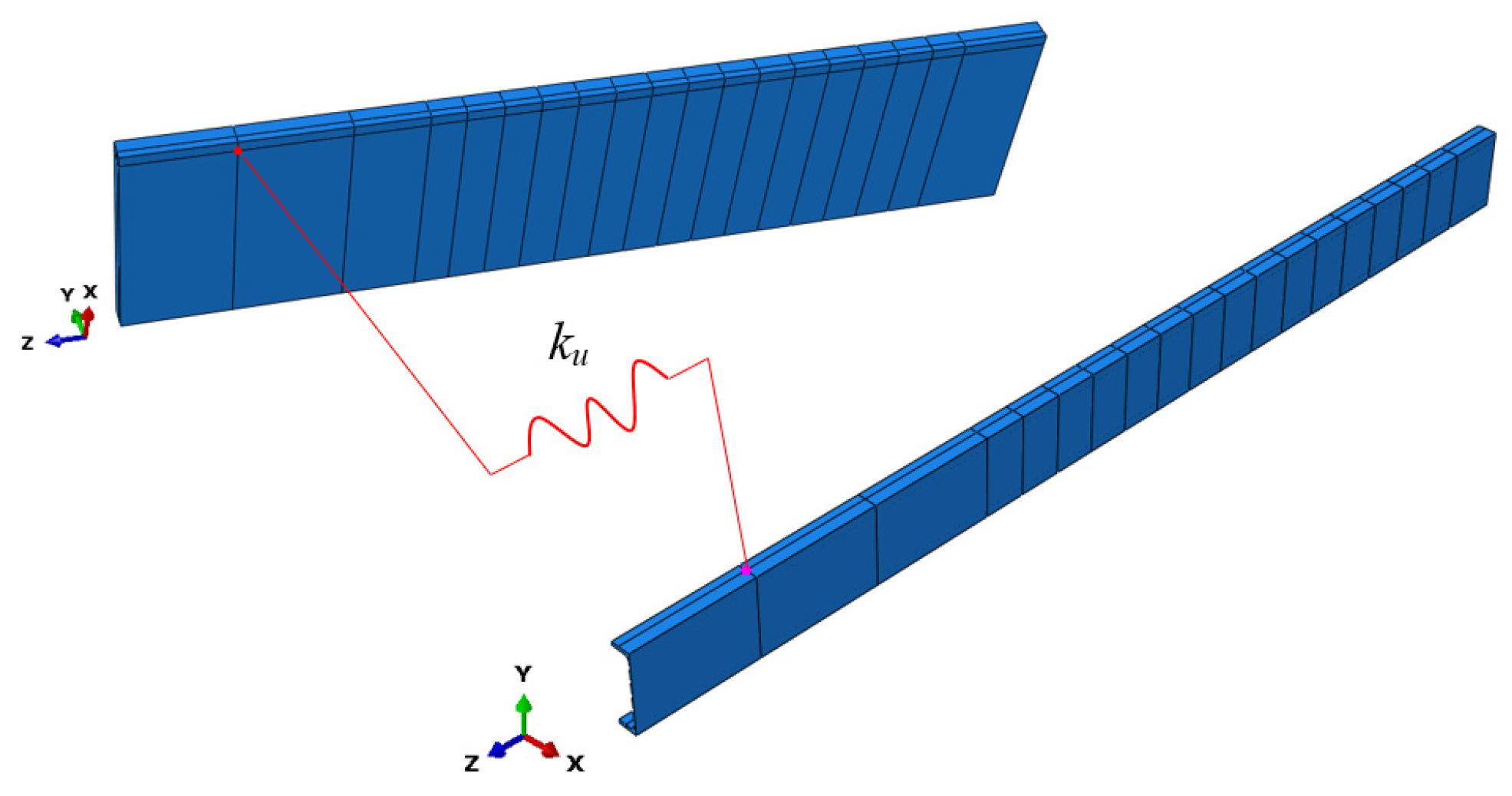
The structural behaviour of the analysed beams was investigated using numerical simulations in the Abaqus program. Each numerical model consisted of a girder, a slab, and loading and support plates. Furthermore, each beam had two planes of symmetry. For this reason, only 1/4 of each beam was modelled in the program (Figure 6). The deflection of the beams was measured in the middle of the model, while the slip was measured at its end (Figure 7). An advanced material modelling approach was used, which accounted for both plastic behaviour and failure mechanisms. This enhanced representation enables a more realistic simulation of the structural response, particularly under the loading conditions approaching the ultimate capacity, and provides a reliable basis for assessing the performance of the analysed composite beams.
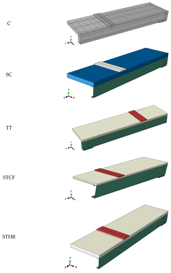
Figure 6.
Numerical models of the concrete and composite beams.
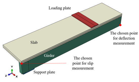
Figure 7.
A model of the timber–timber composite beam (1/4 of the beam).
The behaviour of concrete was described using the concrete damaged plasticity model (Table 3). The model from the article [44] was used with some modifications improving convergence, i.e., the dilatation angle equal to 40 instead of 31, and the viscosity parameter equal to 0.0001 instead of 0.0.

Table 3.
The concrete damaged plasticity model [44].
LVL was modelled as an orthotropic material, and its failure was predicted due to the use of Hill’s function (Table 4). LVL X was used with twenty percent of veneers crossbanded. The engineering constants for the orthotropic material were based on [45]. The LVL slab was divided into two zones (compression and tension), taking into account the position of the plastic neutral axis. For this reason, two LVL models were used in one slab. This solution was also applied by Kawecki and Podgórski in a numerical model of a timber beam [46]. The parameters of Hill’s function were calculated using the equations from [47,48]. The compressive, tensile, and shear strengths of the LVL were based on the manufacturer’s declaration [49]. The compressive strength was used as the reference value for the coefficients in compression, while the tensile strength was used in tension (Table 5). It is important to note that the elastic behaviour of LVL was described using the identified values of elastic and shear moduli presented in [45]. However, the parameters of Hill’s function were only calculated based on the LVL strength values. They were not calibrated due to the lack of laboratory tests.

Table 4.
Model of laminated veneer lumber.

Table 5.
Parameters of Hill’s function applied in the LVL model.
Glued laminated timber (GLT) was described as an orthotropic material and its failure was predicted using Hill’s function (Table 6). The engineering constants were based on [48], while the compressive, tensile, and shear strengths of GL24 h were based on the characteristic material strengths from [50]. The tensile strength was used as a reference value for Hill’s coefficients (Table 7). These coefficients were not calibrated due to the lack of laboratory tests of GLT specimens.

Table 6.
Material model of glued laminated timber.

Table 7.
Parameters of Hill’s function applied in the GLT model.
B500S grade steel used in rebars and stirrups was described as an elastic–perfectly plastic material (E = 200 GPa, ν = 0.3, fy = 500 MPa). S235 grade steel used in hot-rolled girders and plates, and S320GD grade steel used in cold-formed girders were modelled based on [51,52]. The engineering stress–strain relationships were converted to true stress–strain relationships (Table 8). The dimensions of the loading plates were 20 × 200 × 1450 mm (concrete beam) and 20 × 200 × 1250 mm (composite beams), whereas the dimensions of the supports plates were 20 × 200 × 250 mm (concrete beam), 20 × 160 × 250 mm (timber–timber composite beam), 20 × 150 × 250 mm (steel–timber composite beam with a cold-formed girder), and 20 × 100 × 250 mm (steel–timber composite beam with a hot-rolled girder). The wide support plates were used to reduce the bearing stress. The length of the loading and support plates was adjusted to the width of the girders and slabs.

Table 8.
Steel parameters.
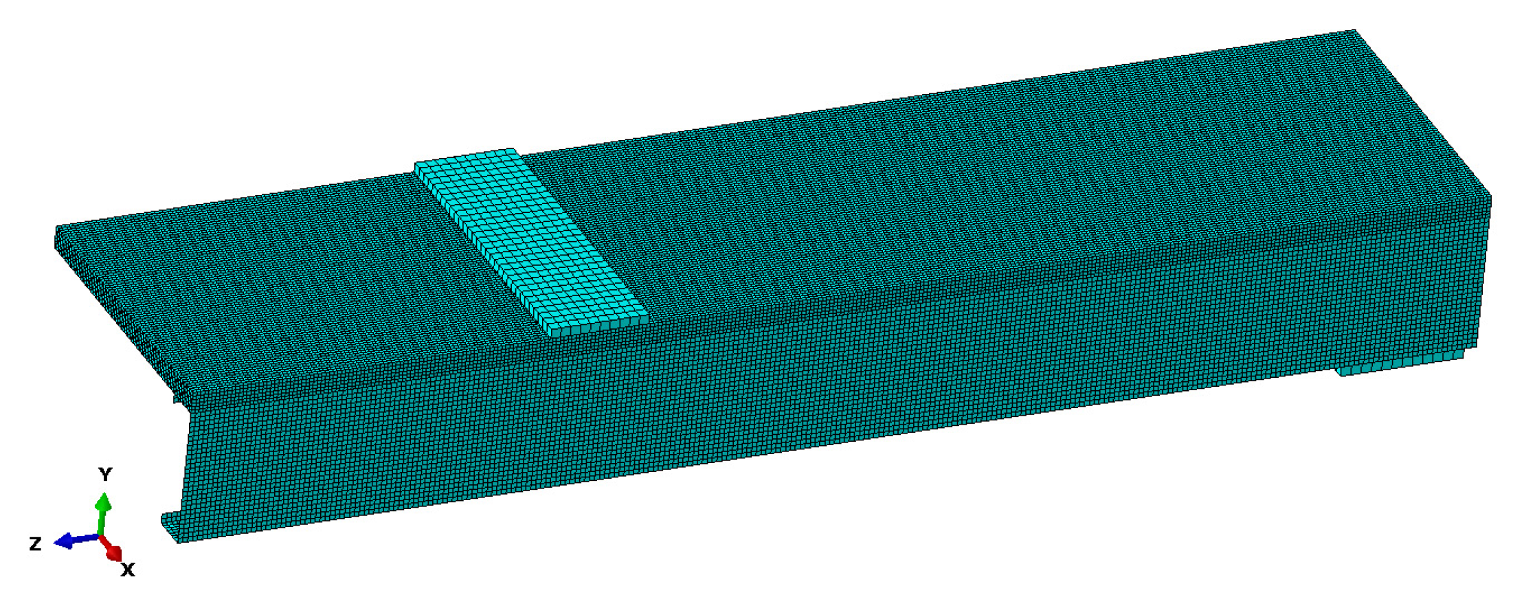
The discretization strategy applied in the numerical analyses is presented in Table 9 and schematically depicted in Figure 8. The table specifies the types of finite elements and the mesh densities assigned to different regions of the model.

Table 9.
Mesh used in the numerical models.
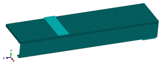
Figure 8.
Mesh used in a steel–timber composite beam with a cold-formed girder.
The rebars and the stirrups were embedded in the concrete beam. In each model of the composite beam, the contact between the beam and the steel plates was modelled. Surface-to-surface hard contact limited the penetration of the steel plates into the beam elements. The friction between the steel and timber elements, and between the steel and concrete elements, was taken into account using a coefficient of 0.3 based on the articles [53,54]. Dorn et al. observed that the friction coefficient between LVL and steel ranged between 0.1 and 0.3 for smooth steel surfaces [53]. Guezouli and Lachal calibrated friction coefficients between the steel flange girder and the concrete slab and between the studs and the concrete [54]. They analysed coefficients of 0.0, 0.1, 0.2, 0.3, 0.4, and 0.5, and observed that the load-slip curve from the numerical simulation with both friction coefficients of 0.3 was close to the reference curve from the experiment. The smallest difference between the numerical and experimental results was obtained for the coefficients of 0.2 (the coefficient between the steel flange girder and the concrete slab) and 0.3 (the coefficient between the studs and the concrete). In this paper, the coefficient of 0.3 was used both for the friction between the steel and timber elements and between the steel and concrete elements. In the case of composite beams with full shear connections, the slabs were connected with the girders using a tie option—a function often used for this type of beams [55]. In the case of composite beams with partial shear connections, discrete connections were used. Between the points located on the girders and the slabs, zero-length springs were created (Figure 9). The spring locations corresponded to the locations of the screws presented in Figure 3, Figure 4 and Figure 5. The stiffness of each spring was calculated using the equation for slip modulus provided in Eurocode 5 [56] and in [29]. The stiffness of the spring in the timber–timber and steel–timber composite beams was 2576.5 N/mm and 3657.8 N/mm, respectively. The constitutive behaviour of zero-length springs was linear. In the beams without connections, the friction between the slabs and the girders was considered.
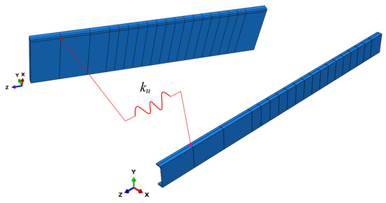
Figure 9.
One of the zero-length springs used in the steel–timber composite beam with partial shear connections.
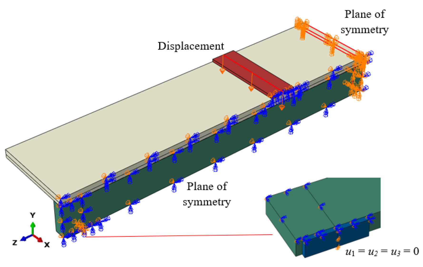
The load was applied in the form of a displacement to the loading plates. In the case of beams with LVL slabs, the displacement was applied to the centre line of the loading plate. In the case of beams with concrete slabs, the displacement was applied to the entire upper surface of the loading plate. Surface loading was used because of the convergence problem at the beginning of the numerical analysis. This approach reduced the likelihood of local damage under the loading plate in the concrete slabs compared to the timber ones. The boundary conditions, including the planes of symmetry and the fixed displacements, are presented in Figure 10.
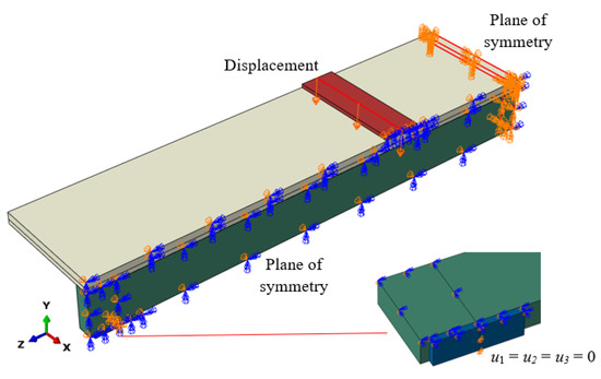
Figure 10.
Boundary conditions with planes of symmetry.
It should be emphasised that the numerical models developed in the present study were not directly validated against experimental results, since composite beams with the considered geometry and dimensions have not been tested in laboratory conditions. However, the modelling approach was founded on the authors’ prior experimental and numerical research, in which similar composite beam systems were investigated [9,29]. The experience and insights gained from these earlier studies provided a solid basis for the development of the present finite element models. The material models used in this study were based on the literature. The behaviour of concrete was described using the concrete damaged plasticity model from the article [44]. The stress–strain relationship for S320GD grade steel was discussed in [52]. The elastic parameters of LVL and GLT were based on [45,48]. The parameters of Hill’s function were calculated from the LVL strength values. These parameters were not calibrated due to the lack of laboratory tests.
3. Results
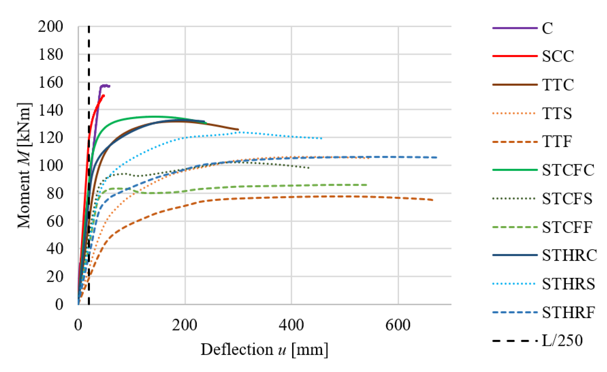
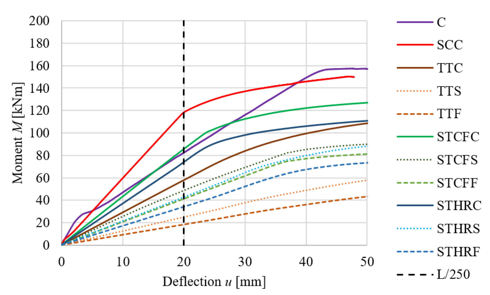
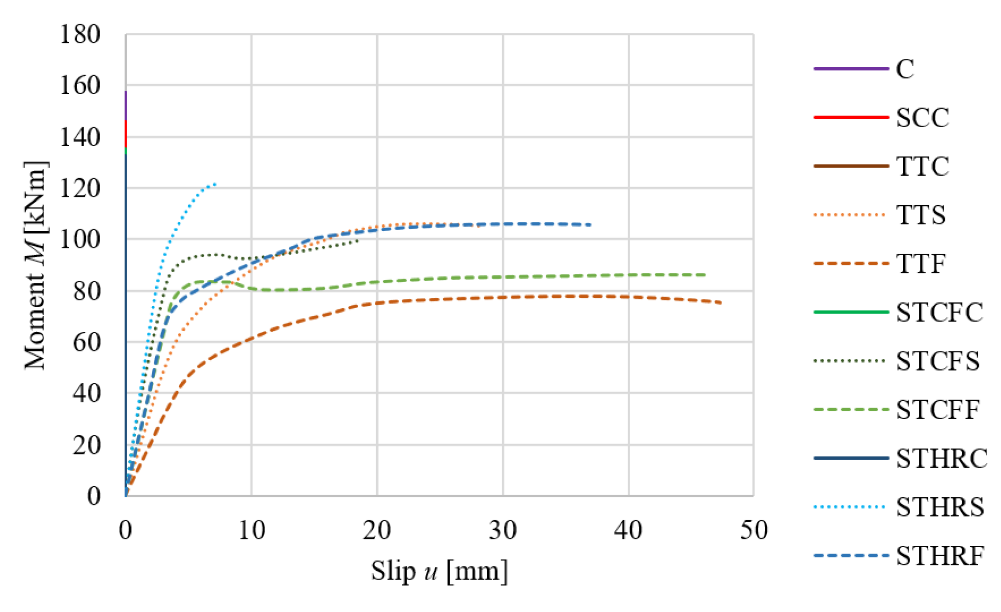
In the numerical experiments, the concrete beam and the composite beams were analysed using four-point bending. Each member was subjected to combined shear and bending in the support region and to pure bending in the midspan region. The bending was unidirectional, i.e., the beam bent in the plane perpendicular to the major axis of the cross-section. In the adopted coordinate system (Figure 10), this corresponded to bending about the x-axis, shear along the y-axis, and deflection in the y-direction. From the perspective of assessing the load-bearing capacity of the investigated composite beams, the key aspects are the relationship between the bending moment and the mid-span deflection (see Figure 11 with a full deformation range and Figure 12 with a reduced deformation range adopted for improved clarity of the results), as well as the slip along the interface between the girder and the slab at the support zone (Figure 13).
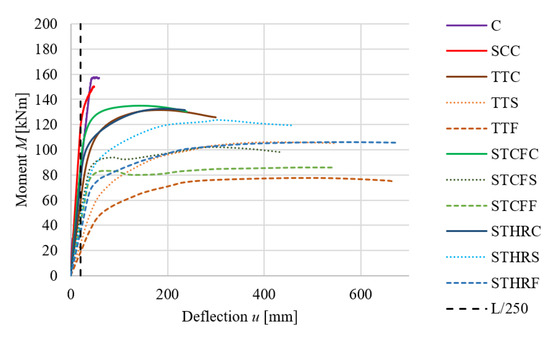
Figure 11.
Mid-span deflection–moment relationships for the analysed beams (full deformation range).
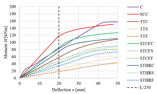
Figure 12.
Mid-span deflection–moment relationships for the analysed composite beams (reduced deformation range, i.e., 0–50 mm).
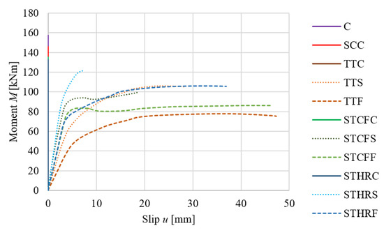
Figure 13.
End slip–moment curves relationships.
Table 10, Table 11, Table 12 and Table 13 summarise the measured quantities alongside the calculated values of all beams, where N denotes the results of the numerical analysis and T denotes those obtained from the theoretical analysis: elastic bending resistance (Mel), ultimate load-carrying capacity (Mult), mid-span deflection (uel) corresponding to Mel, slip (sel) corresponding to Mel, mid-span deflection (uult) corresponding to Mult, and slip (sult) corresponding to Mult. Particularly, in Table 10, the results for the timber–timber and steel–timber composite beams with full composite action were compared with the concrete and steel–concrete composite beams. It should be noted that for the T-shaped reinforced concrete beam and the composite beams with full composite action, the slip was equal to zero, which is indicated by the vertical lines in Figure 13.

Table 10.
Comparison of the structural behaviour of the concrete beam and composite beams with full shear connections.

Table 11.
Comparison of the structural behaviour of TT beams for different degrees of composite action.

Table 12.
Comparison of the structural behaviour of STCF beams for different degrees of composite action.

Table 13.
Comparison of the structural behaviour of STHR beams for different degrees of composite action.
The effect of the degree of composite action for different composite beam configurations is presented in Table 11, Table 12 and Table 13. Table 11 shows the results for timber–timber composite beams (TT), Table 12 for steel–timber composite beams with cold-formed girders (STCF), and Table 13 for steel–timber composite beams with hot-rolled girders (STHR).
4. Discussion
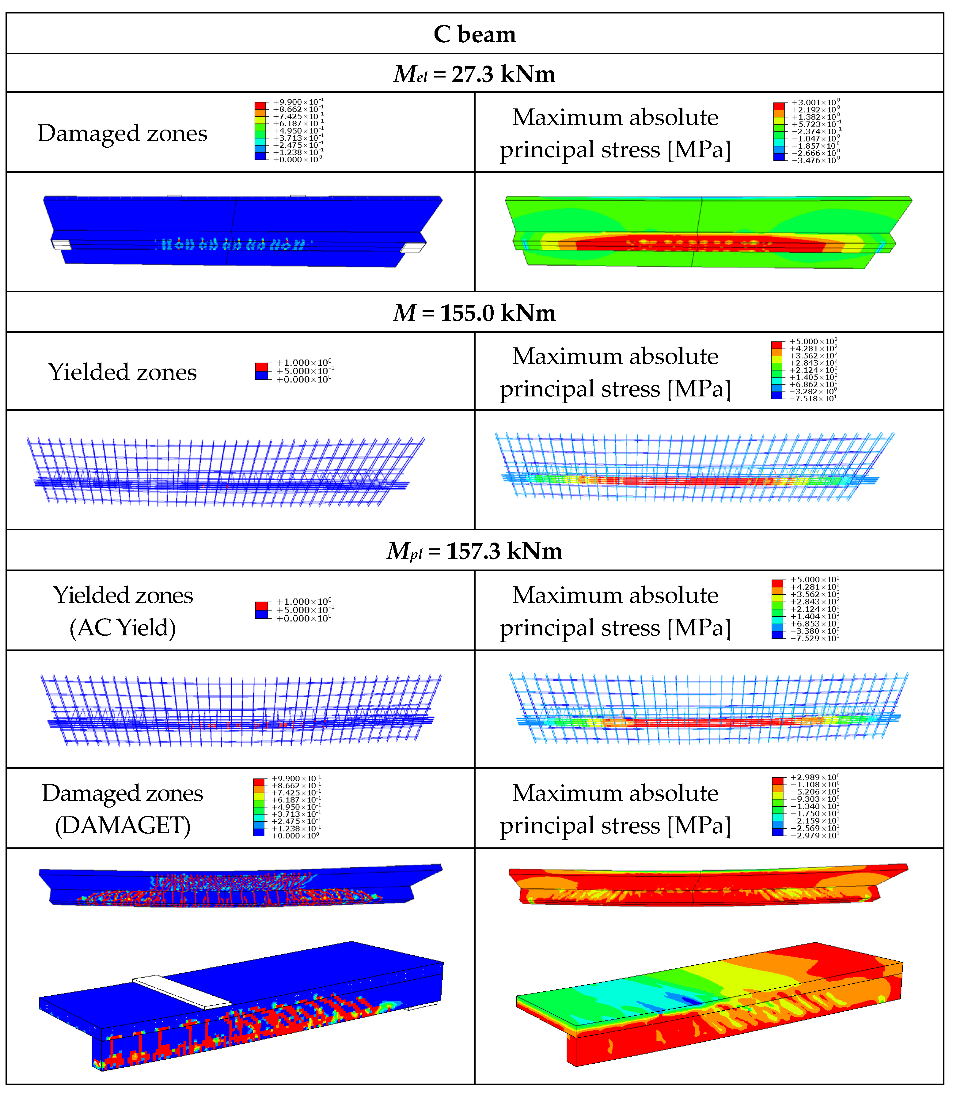
All of the analysed beams reached the ultimate load after exceeding the deflection limit (L/250). This situation demonstrates that ensuring adequate serviceability can become the governing factor in design, even when the structural load-bearing capacity is not exceeded. Reference structural systems commonly employed in multi-storey building construction comprise reinforced concrete T-beams and steel–concrete composite beams. T-beams are characterised by a complete shear connection, which prevents slip in the support regions. In composite beams, full shear interaction is difficult to achieve because the connectors always undergo some level of deformation [57]. However, connections with welded studs used in steel–concrete composite beams are rigid, making it possible to achieve a composite beam with nearly full shear interaction. In this paper, it was assumed that the SCC, TTC, STCFC, and STHRC beams were composite beams with full shear connection (enough fasteners were employed to achieve bending resistance) and full shear interaction (no slip). However, this assumption can be unrealistic, especially for TTC, STCFC, and STHRC beams, due to their flexible connections. The reinforced concrete T-beam and the composite beams with full shear connections had higher stiffness than the composite beams with partial shear connections. The bending resistance of the concrete beam in the numerical analysis was 1.1 times higher than the bending resistance in the theoretical calculations. The slab rebars and the residual strength of concrete could have had an impact on the higher load-bearing capacity of the T-beam in the numerical analysis. A typical load-deflection curve was obtained for a concrete beam, showing three ranges (Figure 14): (the cracking range, the reinforcing rebars yielding range, and the range before the concrete reached its ultimate strain) [58].
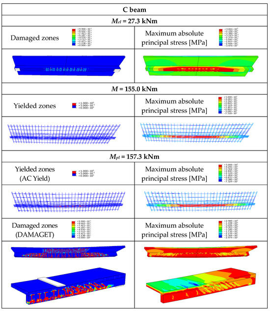
Figure 14.
Yielded zones in the rebars, maximum absolute principal stress, and cracking pattern in the concrete beam (C).
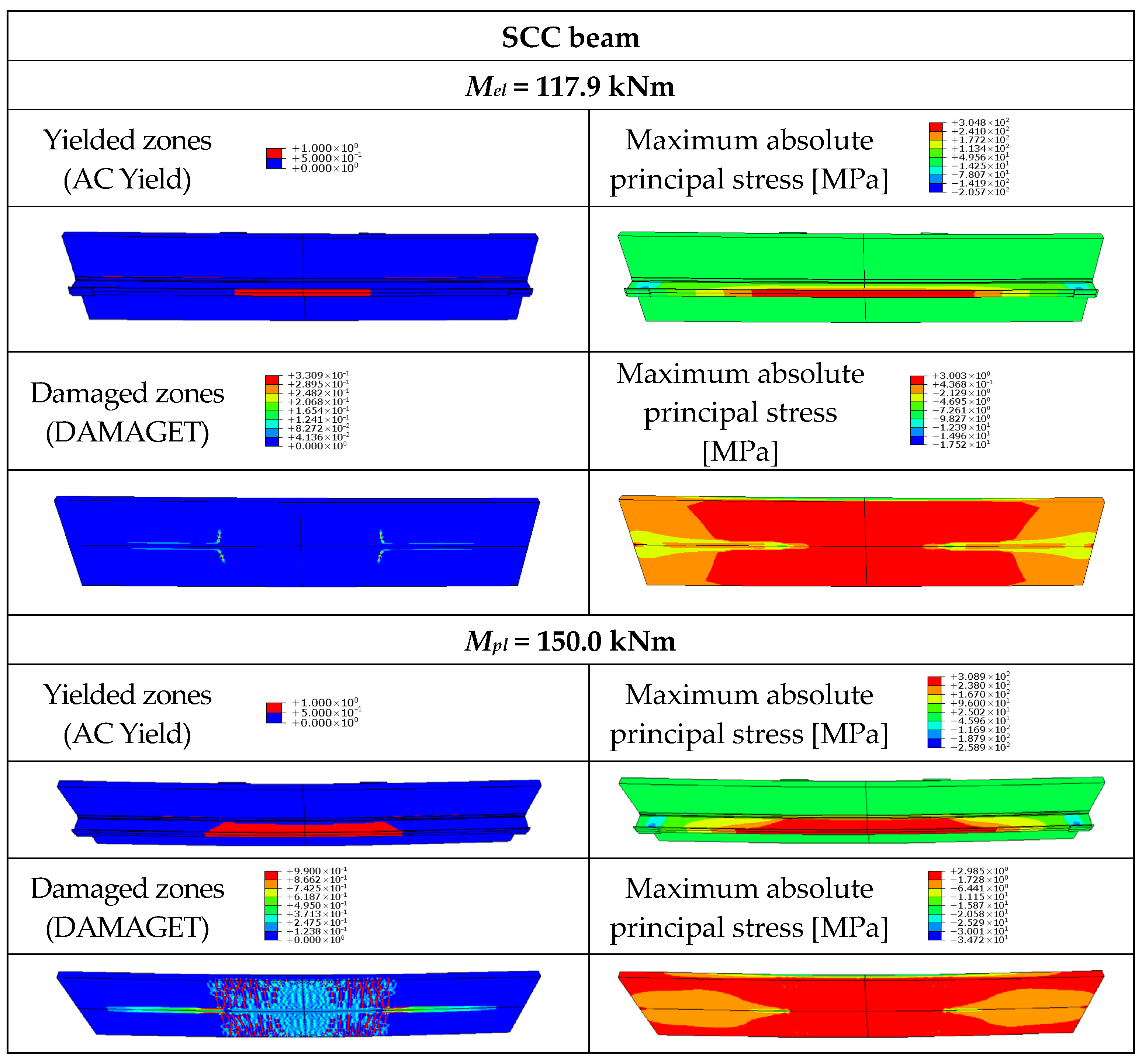
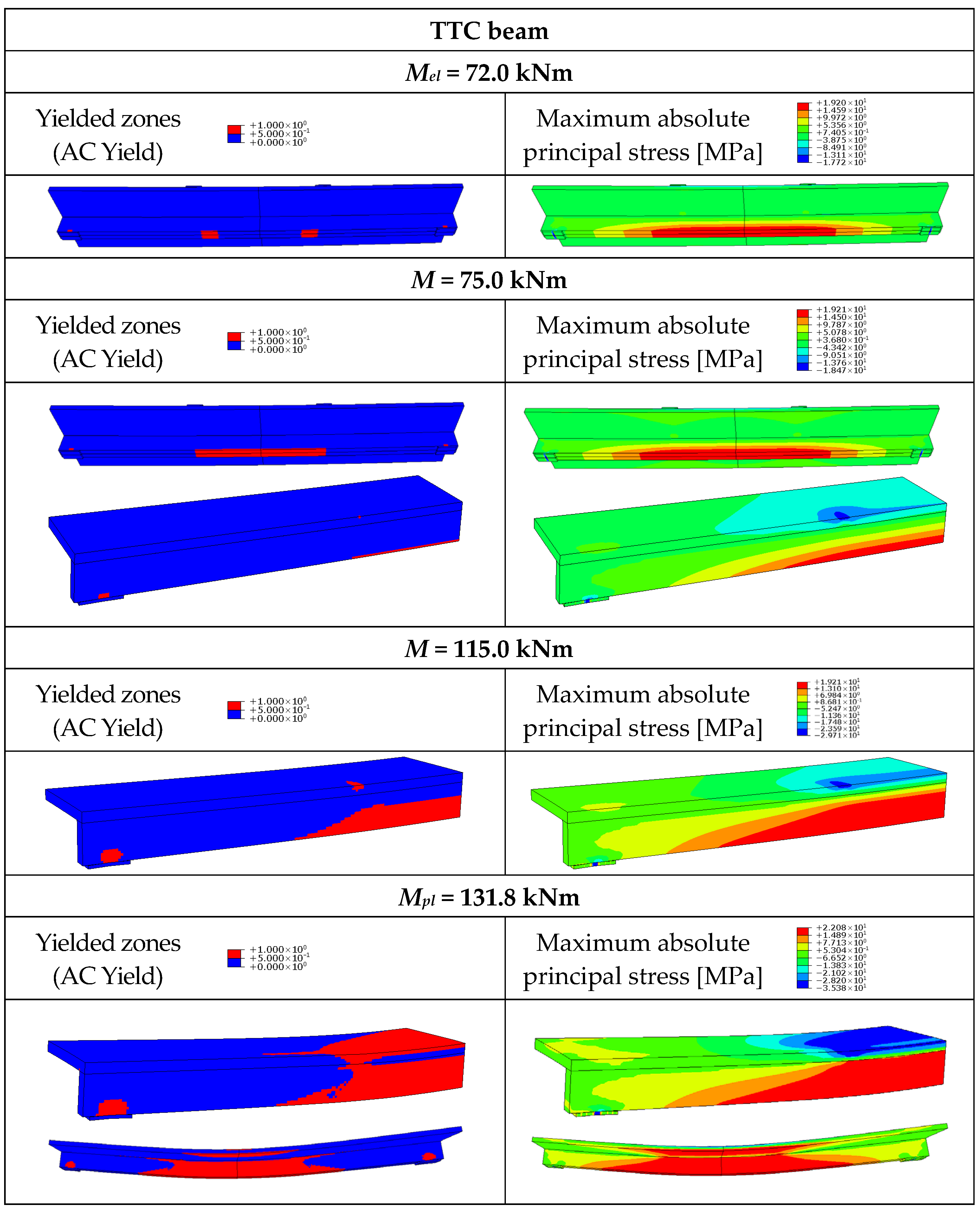
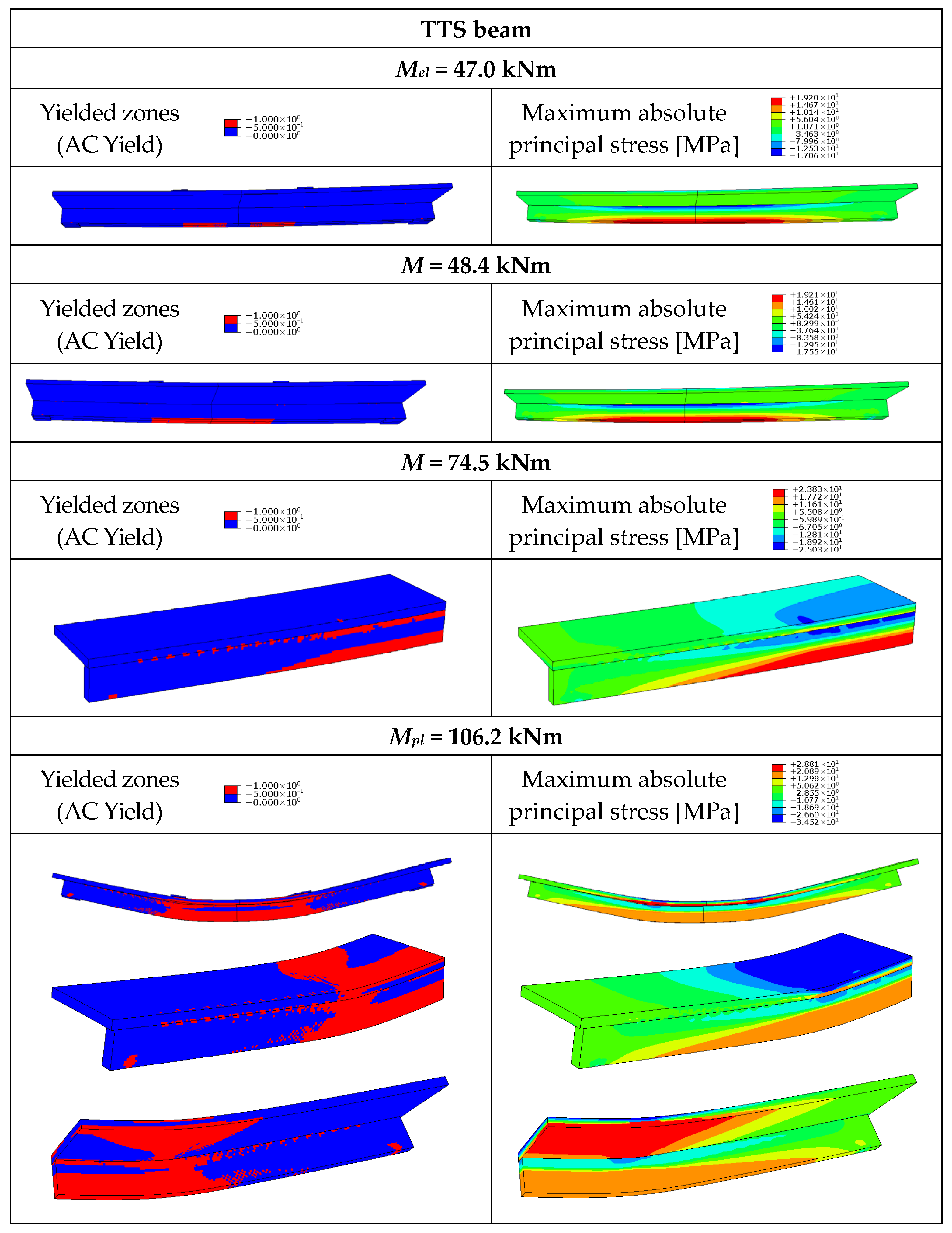
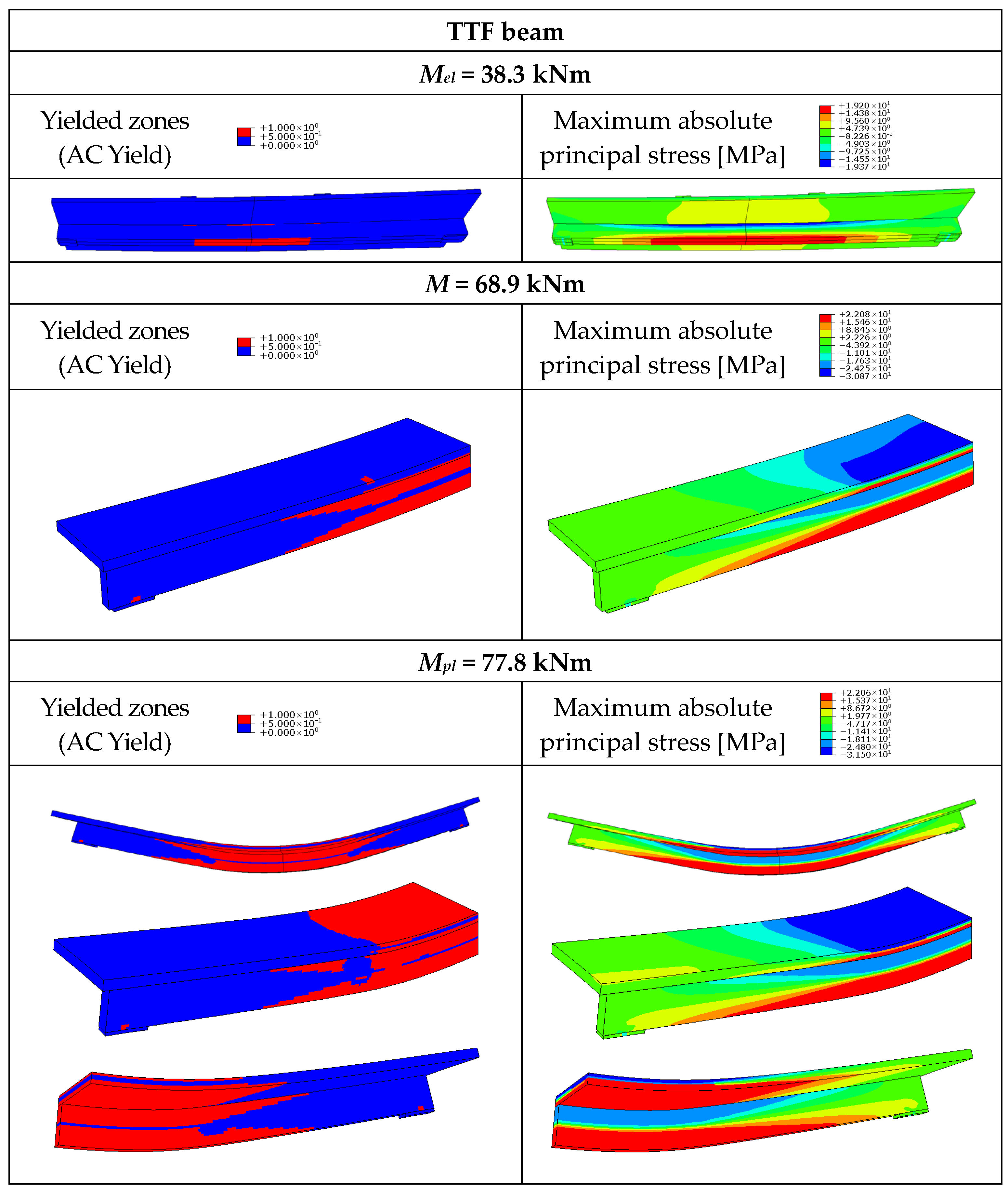
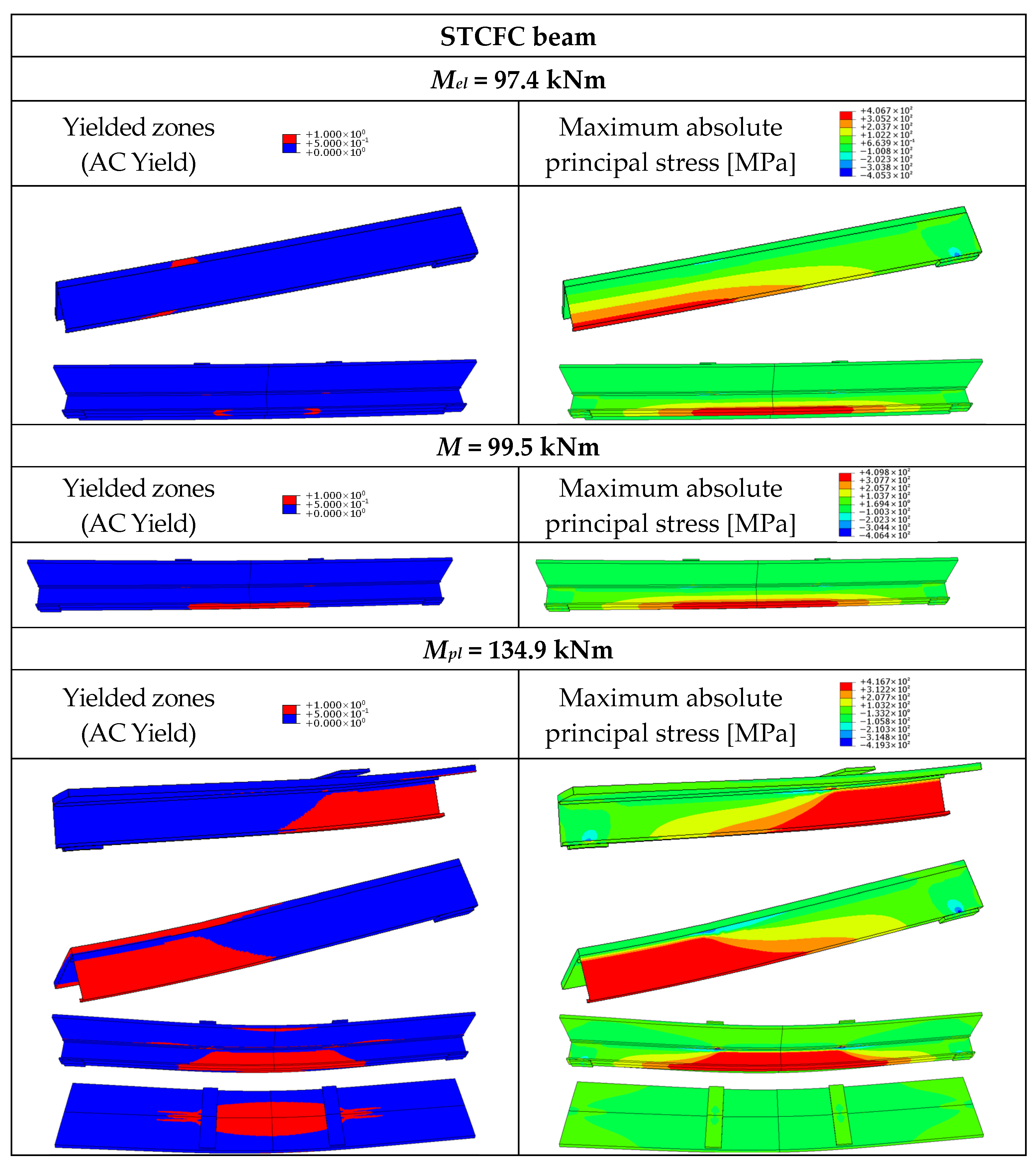
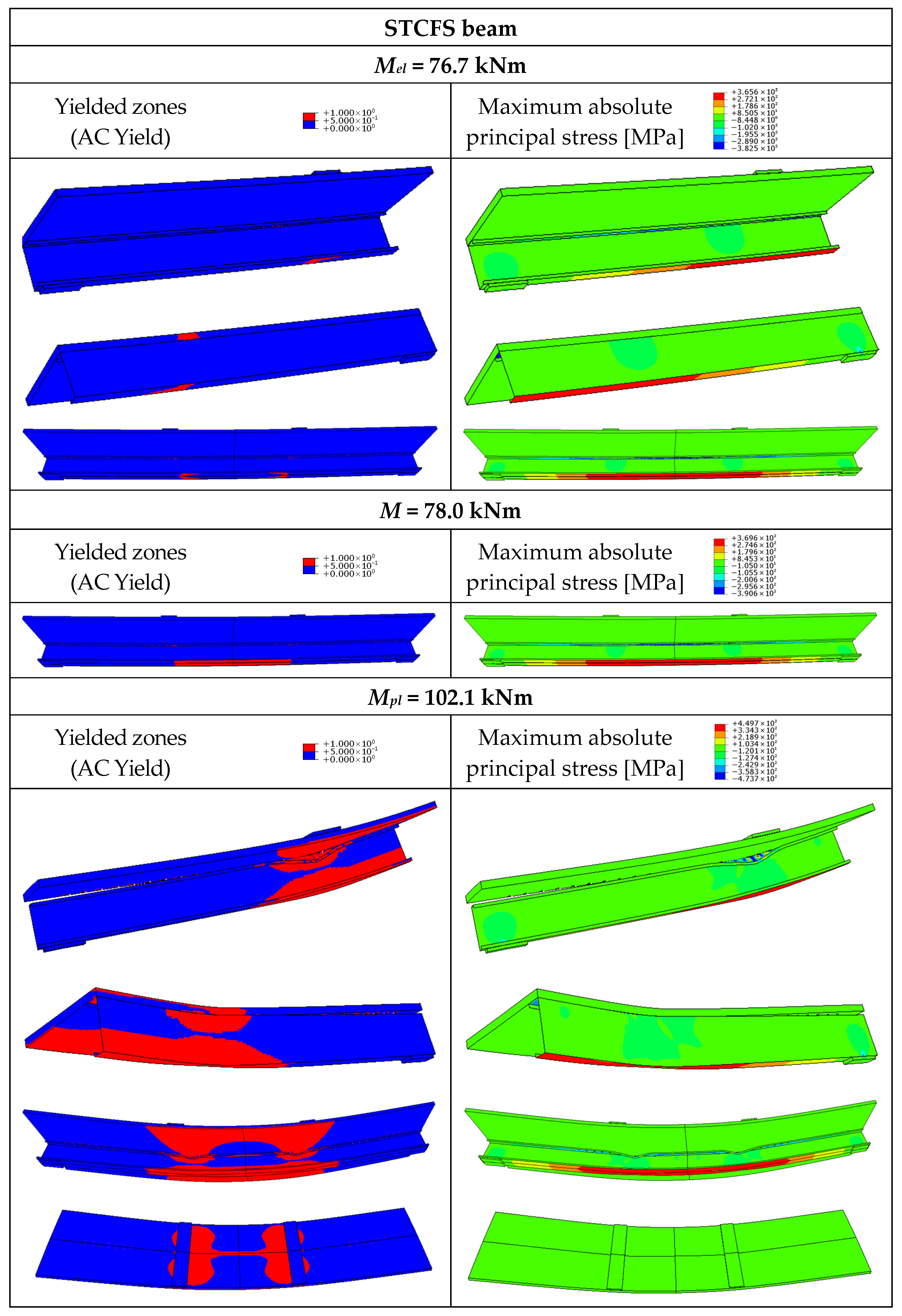
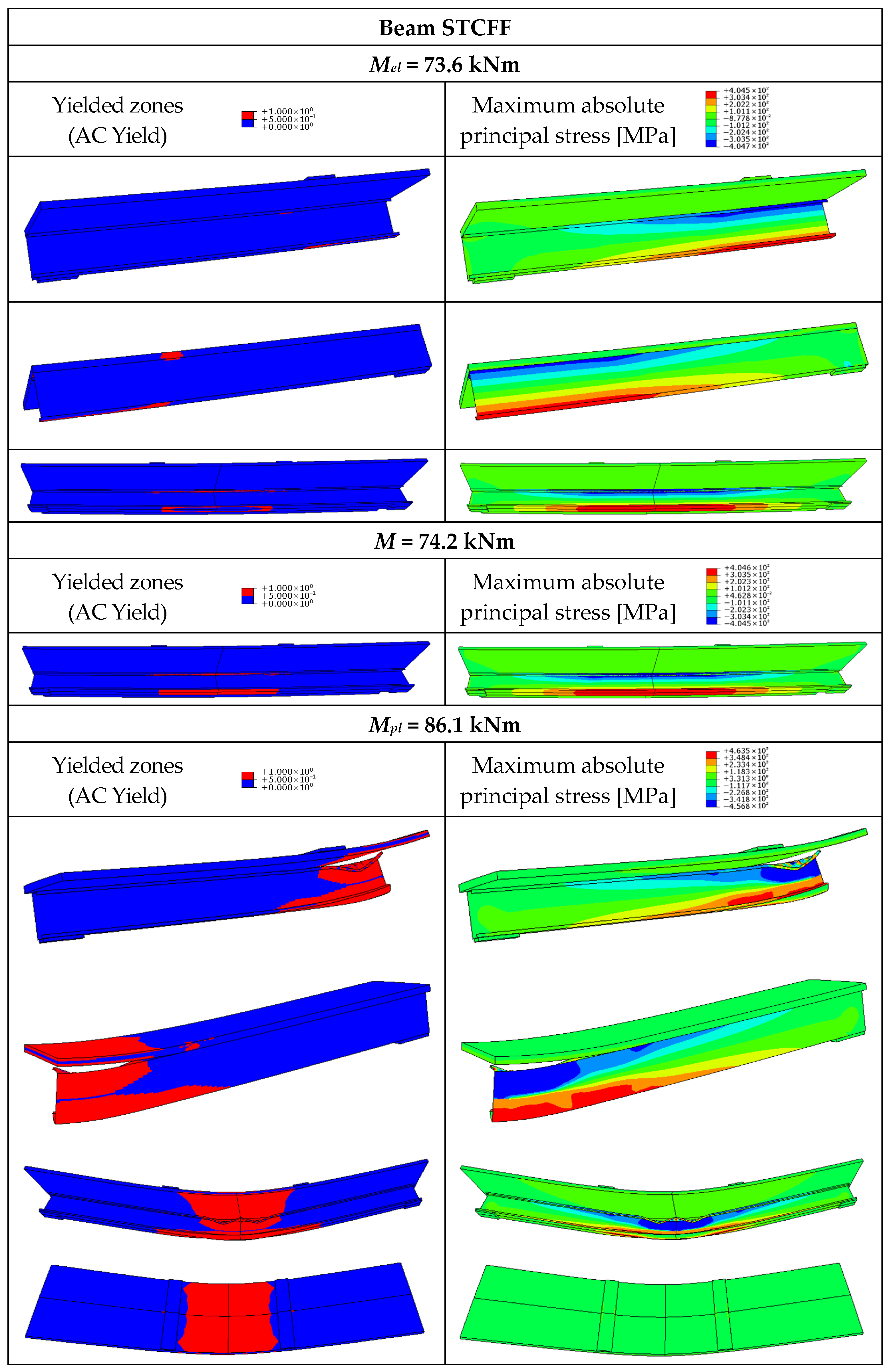
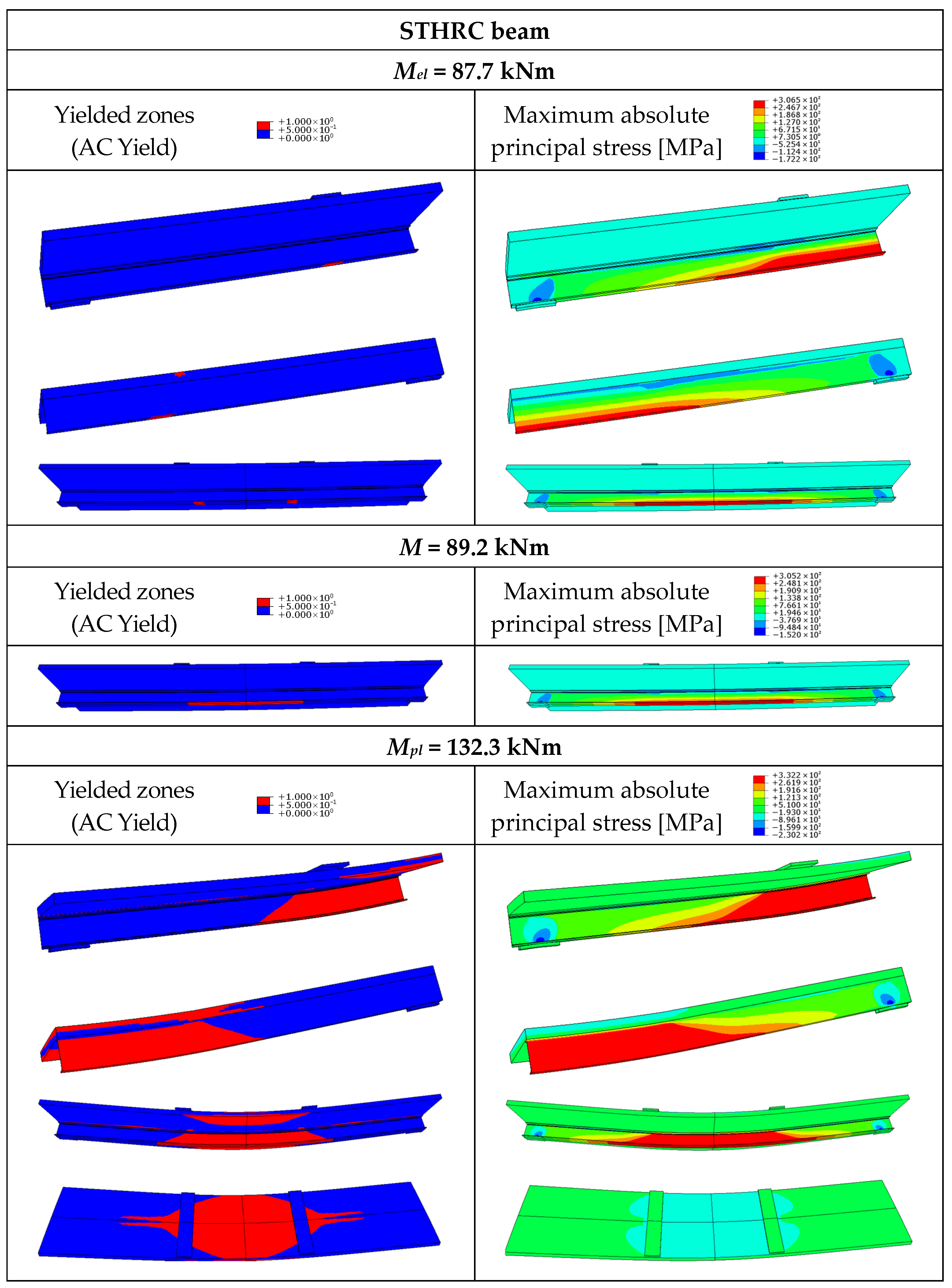
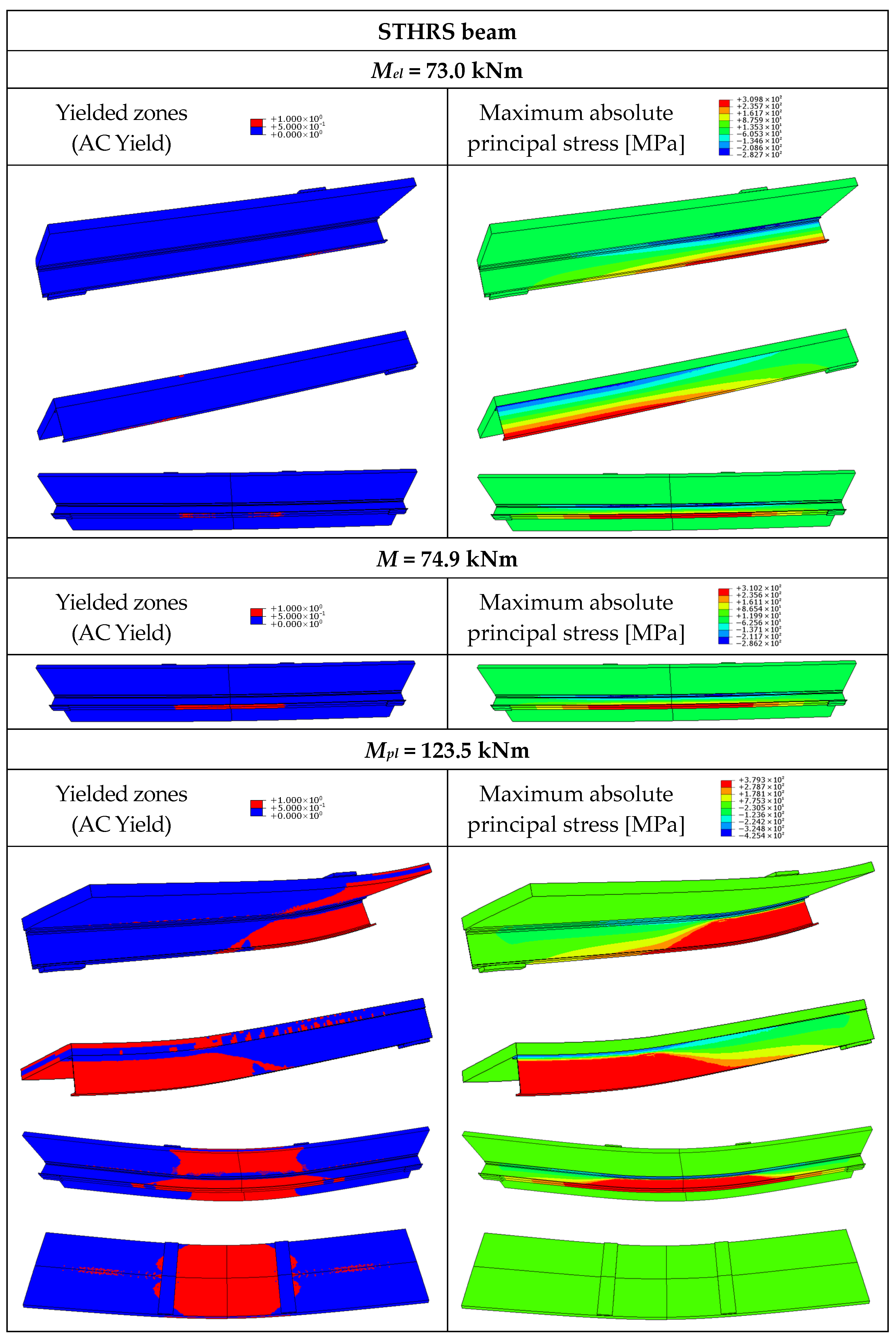
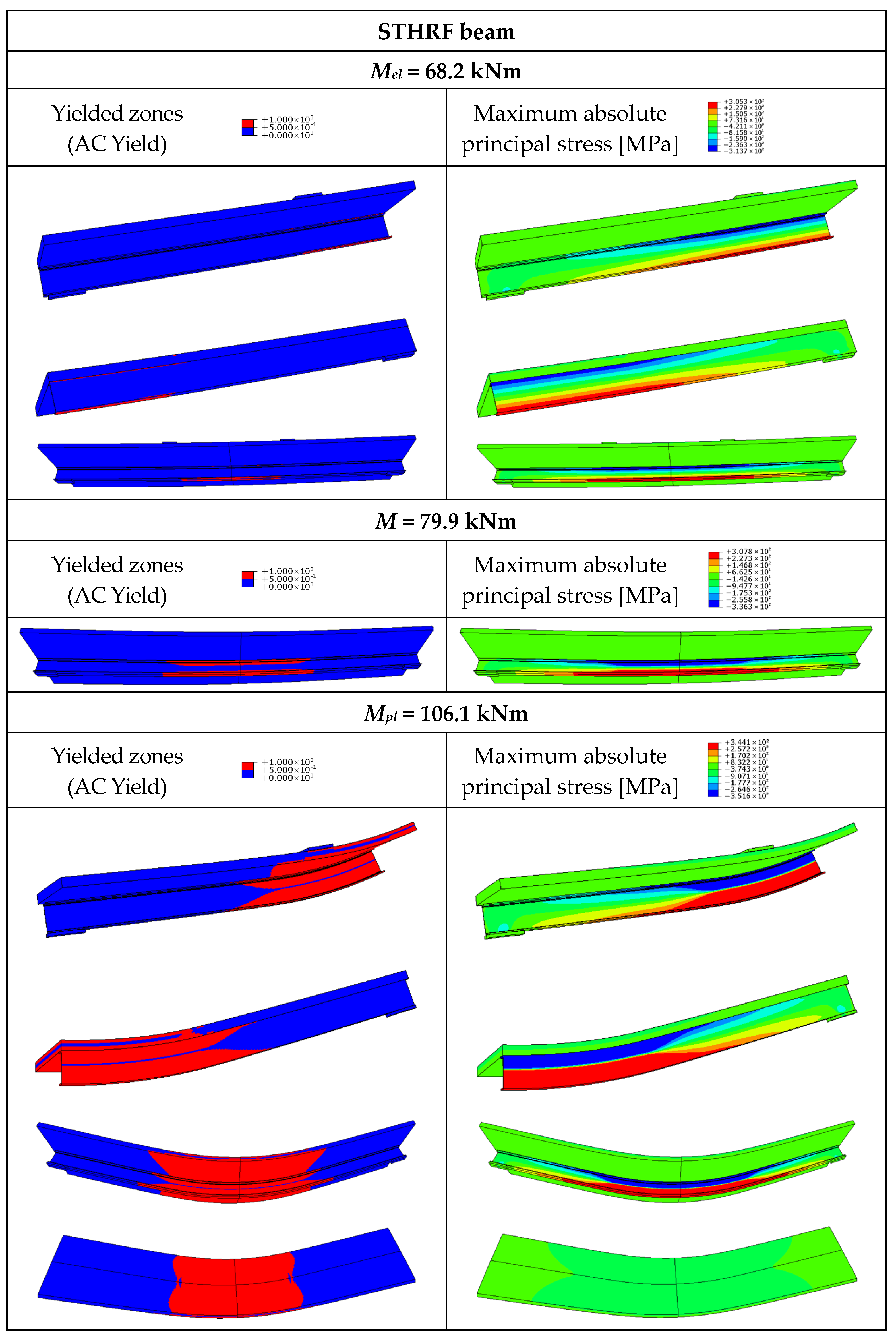
The load-bearing capacity of the steel–concrete composite beam from the numerical analysis (150.0 kNm) was 1.06 times higher than the one from the theoretical study (142.0 kNm). The yield strength of steel was used in the theoretical calculations, whereas the stress–strain relationship with maximum stress equal to the ultimate strength of steel was taken into account in the numerical model. The plastic bending resistance of the composite beams with timber slabs from the numerical simulations (131.8 kNm, 134.9 kNm, and 132.3 kNm) was lower (by factors of 1.08, 1.05, and 1.09) than that from the theoretical calculations (142.6 kNm, 141.9 kNm, and 144.0 kNm) because the numerical model accounted for the failure mode of timber. Furthermore, the theoretical model did not take into account timber orthotropy, whereas the orthotropic models of LVL and GLT were used in the numerical analyses. Last but not least, the slabs under the loading plate were affected by local yielding. The displacement was applied to the centre line of the loading plate, and separation after contact was possible. What is more, local yielding occurred at the girder support in the timber–timber composite beam. The ultimate loads of the composite beams with partial shear connections (106.2 kNm—TTS, 102.1 kNm—STCFS, 123.5 kNm—STHRS) were lower (by factors of 1.24, 1.32, 1.07) than the ultimate loads of the composite beams with full shear connections (131.8 kNm—TTC, 134.9 kNm –STCFC, 132.3 kNm—STHRC). The yielded and damaged zones, the maximum absolute principal stress corresponding to the elastic bending resistance (Mel), and the ultimate load-carrying capacity (Mult) of the analysed beams are presented in Figure 14, Figure 15, Figure 16, Figure 17, Figure 18, Figure 19, Figure 20, Figure 21, Figure 22, Figure 23 and Figure 24.
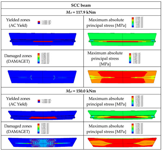
Figure 15.
Yielded zones in the rebars, maximum absolute principal stress, and cracking pattern in the steel–concrete composite beam (SCC).
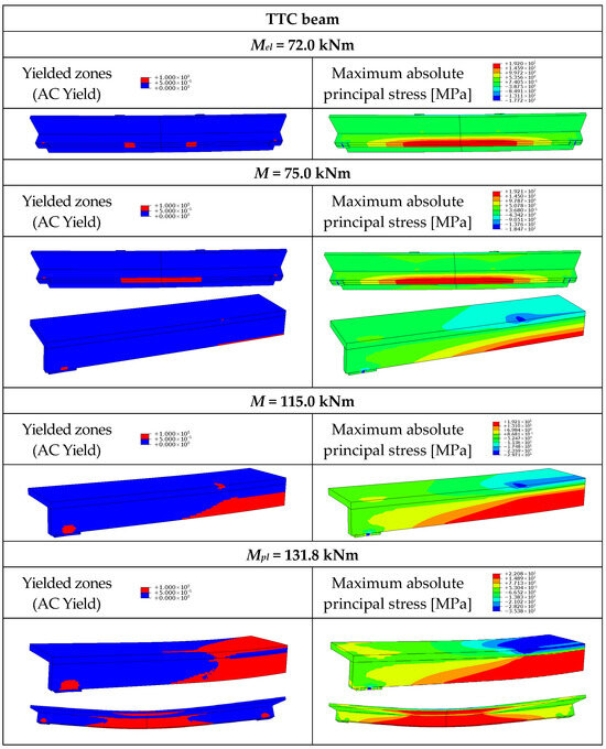
Figure 16.
Yielded zones and maximum absolute principal stress in the timber–timber composite beam (TTC).
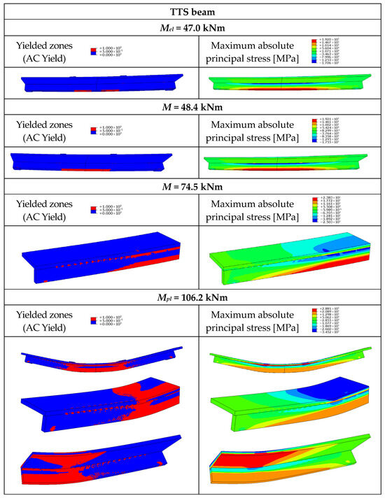
Figure 17.
Yielded zones and maximum absolute principal stress in the timber–timber composite beam with partial shear connections (TTS).
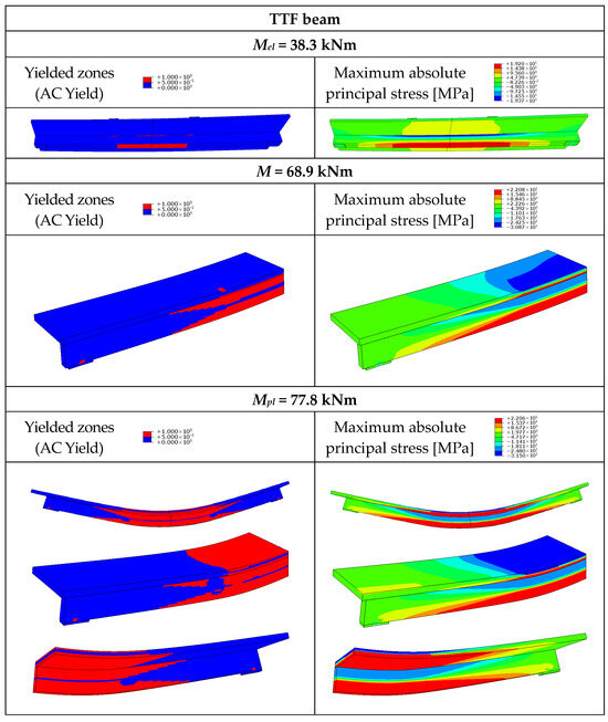
Figure 18.
Yielded zones and maximum absolute principal stress in the timber–timber beam without connections (TTF).
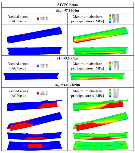
Figure 19.
Yielded zones and maximum absolute principal stress in the steel–timber composite beam with the cold-formed girder and full composite action (STCFC).
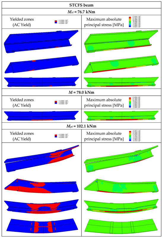
Figure 20.
Yielded zones and maximum absolute principal stress in the steel–timber composite beam with the cold-formed girder and partial shear connections (STCFS).
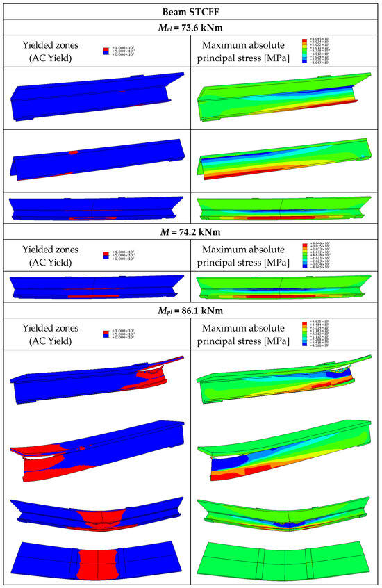
Figure 21.
Yielded zones and maximum absolute principal stress in the steel–timber composite beam with the cold-formed girder and without connections (STCFF).
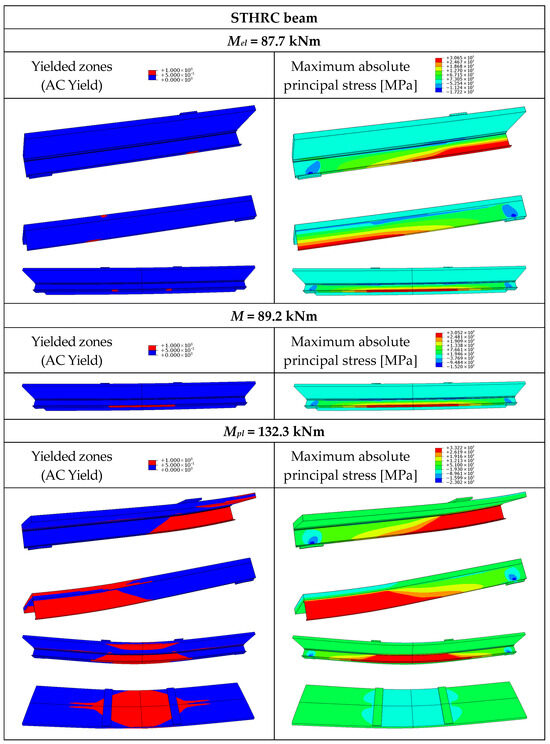
Figure 22.
Yielded zones and maximum absolute principal stress in the steel–timber composite beam with the hot-rolled girder with full composite action (STHRC).
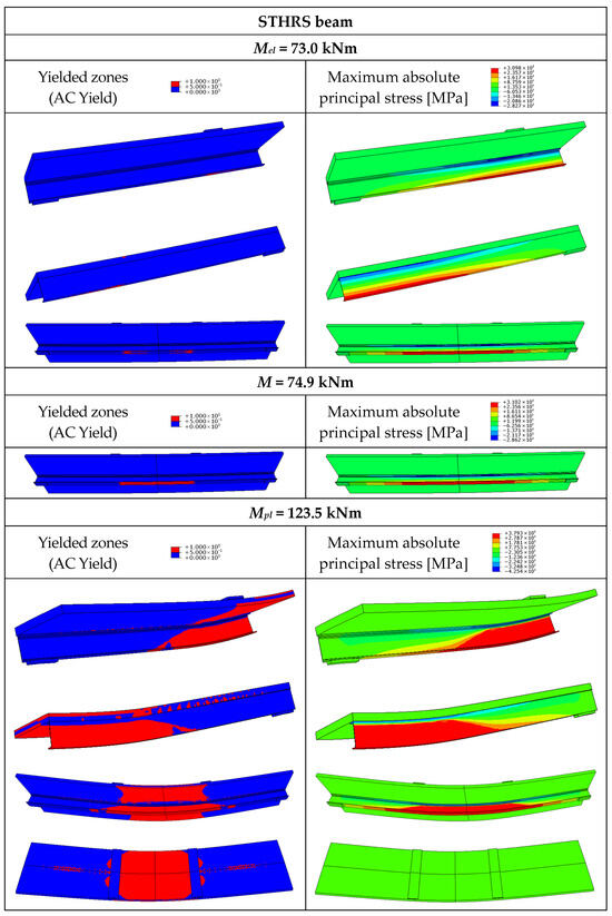
Figure 23.
Yielded zones and maximum absolute principal stress in the steel–timber composite beam with the hot-rolled girder and partial shear connections (STHRS).
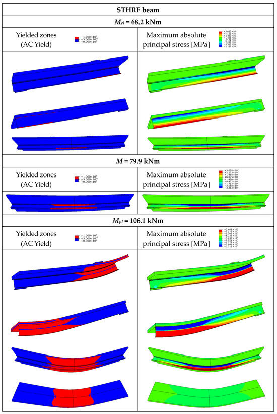
Figure 24.
Yielded zones and maximum absolute principal stress in the steel–timber composite beam with the hot-rolled girder and without connections (STHRF).
When the load reached 17% of Mult, vertical cracks occurred in the concrete T-beam (Figure 14). The length of the cracks continuously increased during the numerical analysis. The yielding of the rebars occurred at 99% of the ultimate load. The failure mode of the concrete T-beam was a combination of vertical cracks in the part of the girder subjected to pure bending and diagonal cracks in the section of the girder subjected to combined shearing and bending. The tensioned edge of the slab was cracked in the middle section of the T-beam (Figure 14).
The yielding of the bottom flange of the steel girder and the horizontal crack in the slab were observed in the SCC beam for the load equal to the elastic bending resistance of the beam (Figure 15). The failure mode of the SCC beam was a combination of horizontal cracking in the slab and yielding of the steel girder.
The tensile strength of GLT was achieved in the bottom edges of the timber girder for the load equal to the elastic bending resistance of the TTC beam (Figure 16). In the case of the TTS beam, partial composite action was observed. The stress in the lower edge of the girder was higher than in the upper edge (Figure 17).
For the TTF beam, timber strength was achieved at both the lower and upper edges of the girder (Figure 18) due to the presence of two neutral axes in the non-composite beam. When the load reached Mel, the TTC and TTS composite beams exhibited yielded zones closer to the loading plates rather than at midspan (Figure 16 and Figure 17). Shortly afterwards, yielded zones were observed in the centre of the beams. Local yielding occurred in the slabs under the loading plates of the TT beams for the moment of 68.9–75.0 kNm (75 kNm—TTC, 74.5 kNm—TTS, 68.9 kNm—TTF).
When the load reached Mpl, timber strength was achieved over the entire height of the cross-section under the loading plate of the TTC beam (Figure 16). As for the mid-span cross-section, LVL strength was achieved in the upper edge of the slab, and GLT strength was achieved over the entire height of the girder cross-section. One neutral axis was observed in this beam. In the case of the TTS beam, partial composite action was observed. The yielded zone of the slab due to compression was more extensive than the yielded zone due to tension, and the yielded zone of the girder due to tension was more extensive than the yielded zone due to compression. As for the TTF beam, two neutral axes were observed. The components of the beams worked as separate elements (Figure 18).
In the STCF beams, the yielding of the bottom flanges of the thin-walled girders and the local yielding in the slabs under the loading plates occurred for the load equal to Mel (Figure 19, Figure 20 and Figure 21). The beams exhibited yielded zones closer to the loading plates rather than at midspan. Shortly after exceeding the value of Mel, yielded zones were observed in the centre of the beams. As for the STCFF beam, the yielding occurred both in the lower and upper flanges of the thin-walled girder due to the formation of two neutral axes in the non-composite beam. When the load reached the value of Mpl, LVL strength was achieved in the upper edge of the slab, and the yield strength of steel was achieved over the entire height of the thin-walled girder in the STCFC beam (Figure 19). Local buckling was prevented in the beam with full composite action due to the fact that the neutral axis was located in the LVL slab, and the cold-formed girder was subjected to tension. Partial composite action was observed in the STCFS beam (Figure 20) and two neutral axes were observed in the STCFF beam (Figure 21). In the STCFS beam with partial composite action and the STCFF beam with no composite action, the cold-formed girders were subjected to both compression and tension. The local plastic mechanism, i.e., flange crumpling, was observed in the STCFS and STCFF beams (Figure 20 and Figure 21). Local buckling was not observed in these beams because imperfections were not reflected in their numerical models. For this reason, the load-bearing capacity of the STCFS and STCFF beams could have been overestimated.
The yielding of the bottom flanges of the steel girders was observed in the STHRC and STHRS beams (Figure 22 and Figure 23). In the case of the STHRF beam, the yield strength was achieved both in the top and bottom flange of the girder (Figure 24). When the load reached the value of Mpl, a plastic hinge occurred under the loading plate in the STHRC beam (Figure 22). Partial composite action was observed in the STHRS beam (Figure 23) and two neutral axes in the STHRF beam (Figure 24). The components of the STHRF beam worked as separate elements.
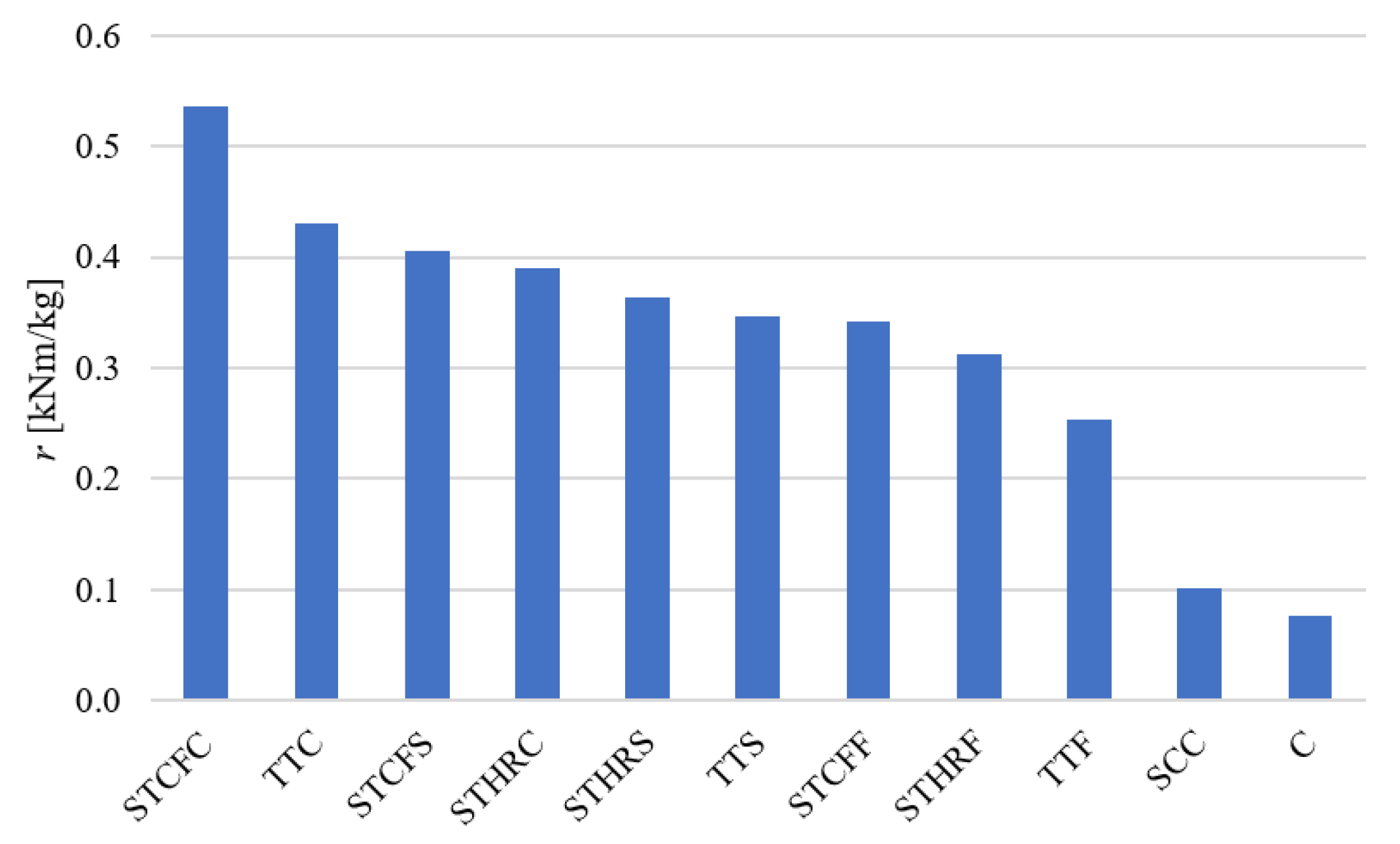
Table 14 presents the bending resistance-to-mass ratios. The steel–timber composite beam with a cold-formed girder exhibited the most favourable ratio (Figure 25). The use of this type of composite beam can help reduce material and assembly costs. All composite beams with timber slabs had higher resistance-to-mass ratios than concrete and steel–concrete composite beams.

Table 14.
Bending resistance-to-mass ratios (r) for the analysed beams.
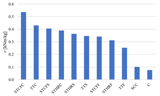
Figure 25.
Comparison of the bending resistance-to-mass ratios.
5. Conclusions
In this paper, the behaviour of relatively new timber–timber and steel–timber composite beams was compared with the behaviour of concrete and steel–concrete composite beams.
It was found that the concrete beam had the lowest bending resistance-to-mass ratio. The failure mode of the beam was a combination of concrete cracking and rebars yielding. It exhibited the highest initial stiffness until the onset of cracking. Among the tested beams, the steel–timber composite beam showed the most favourable stiffness. However, the beam’s bending resistance-to-mass ratio exceeded only that of the concrete beam. Furthermore, steel–concrete composite beams require labour intensive processes to cast their slabs. The use of timber slabs instead of concrete ones can speed up the construction processes and help reduce CO2 emissions. The timber–timber and steel–timber composite beams exhibited bending resistance similar to that of the steel–concrete composite beam. They can be easily deconstructed at the end of their service life if demountable shear connectors are used. However, the stiffness of the composite beams with timber slabs was lower than that of the steel–concrete composite beam. For this reason, the serviceability limit state may be more difficult to meet for such structures. The degree of shear connection in the composite beams with timber slabs had a strong impact on their load-bearing capacity, stiffness, and end-slip. The ultimate loads of the TTS, STCFS, and STHRS beams with partial shear connections were lower by factors of 1.24, 1.32, and 1.07 than the ultimate loads of the composite beams with full shear connections, respectively. Local damage at the supports occurred in timber–timber composite beams due to the low shear strength and low compression strength (perpendicular to grain). Furthermore, Chiniforush et al. observed that brittle tension failure of girders can occur in this type of beam [7]. The steel–timber composite beam with two cold-formed channels used as a girder had the most favourable resistance-to-mass ratio. The use of this type of composite beam can reduce material and assembly costs. However, steel–timber composite beams with cold-formed channels also have certain disadvantages. Their fire resistance is relatively low because of the poor fire performance of their thin-walled girders. Several design guidelines recommended for steel–timber composite beams are presented below. A higher level of composite action should be applied to limit the possibility of the formation of two neutral axes and to prevent local buckling of the girders under compressive stress. In the case of the composite beam with partial composite action, the local plastic mechanism (crumpling of flanges) can reduce the load-bearing capacity and should be taken into account. The connection of the flange to the slab could prevent the local buckling of the flange. In the case of non-composite beams, local buckling should be taken into account. It was not observed in this study since imperfections were not reflected in the numerical model. Steel–timber composite beams with cold-formed girders can be used in floor systems, e.g., in a storage mezzanine.
It should be emphasised that only numerical simulations and theoretical analyses were conducted in this paper. The results of finite element analyses were not weighed against the data from laboratory tests. The analysed beams were subjected exclusively to static loads. The long-term behaviour of composite beams with timber elements should be analysed in the future, along with the influence of fatigue loads, temperature, creep, and moisture content of timber on their load-bearing capacity. In the case of shear connections, the effects of the shear connector type and its diameter were not examined. Further investigation of the influence of varying connection types is recommended. Nevertheless, the analytical and numerical findings presented in this paper establish a foundation for further experimental work.
Author Contributions
Conceptualization, K.C., R.S., M.C., J.Ś., W.S., J.K.G., T.M. and Ł.P.; methodology, K.C., R.S., M.C., J.Ś., W.S., J.K.G., T.M. and Ł.P.; investigation, K.C., R.S., M.C., J.Ś., W.S., J.K.G., T.M. and Ł.P.; writing—original draft preparation, K.C., R.S., M.C., J.Ś., W.S., J.K.G., T.M. and Ł.P.; writing—review and editing, K.C., R.S., M.C., J.Ś., W.S., J.K.G., T.M. and Ł.P.; visualisation, K.C., R.S., M.C., J.Ś., W.S., J.K.G., T.M. and Ł.P. All authors have read and agreed to the published version of the manuscript.
Funding
This research was funded by the Polish Ministry of Science and Higher Education under grant 0412/SIGR/6595.
Institutional Review Board Statement
Not applicable.
Informed Consent Statement
Not applicable.
Data Availability Statement
All data are contained within the article.
Conflicts of Interest
The authors declare no conflicts of interest.
References
- Winchester, N.; Reilly, J.M. The economic and emissions benefits of engineered wood products in a low-carbon future. Energy Econ. 2020, 85, 104596. [Google Scholar] [CrossRef]
- Tupenaite, L.; Kanapeckiene, L.; Naimaviciene, J.; Kaklauskas, A.; Gecys, T. Timber Construction as a Solution to Climate Change: A Systematic Literature Review. Buildings 2023, 13, 976. [Google Scholar] [CrossRef]
- Wdowiak-Postulak, A.; Świt, G.; Dziedzic-Jagocka, I. Application of Composite Bars in Wooden. Full-Scale, Innovative Engineering Products—Experimental and Numerical Study. Materials 2024, 17, 730. [Google Scholar] [CrossRef] [PubMed]
- Navaratnam, S.; Rajeev, P. Load-Carrying Capacity of Laminated Veneer Lumber Joists with Notches and Holes. J. Struct. Eng. 2023, 149, 12. [Google Scholar] [CrossRef]
- Wdowiak-Postulak, A. Numerical, theoretical and experimental model of the static performance of timber beams reinforced with steel, basalt and glass pre-stressed bars. Compos. Struct. 2023, 305, 116479. [Google Scholar] [CrossRef]
- Bakalarz, M.M.; Kossakowski, P.G. Numerical Analysis of Laminated Veneer Lumber Beams Strengthened with Various Carbon Composites. Polymers 2024, 16, 1697. [Google Scholar] [CrossRef]
- Chiniforush, A.A.; Valipour, H.R.; Ataei, A. Timber-timber composite (TTC) connections and beams: An experimental and numerical study. Constr. Build. Mater. 2021, 303, 124493. [Google Scholar] [CrossRef]
- Bedon, C.; Sciomenta, M.; Fragiacomo, M. Mechanical Characterization of Timber-to-Timber Composite (TTC) Joints with Self-Tapping Screws in a Standard Push-Out Setup. Appl. Sci. 2020, 10, 6534. [Google Scholar] [CrossRef]
- Chybiński, M.; Polus, Ł. Theoretical, experimental and numerical study of aluminium-timber composite beams with screwed connections. Constr. Build. Mater. 2019, 226, 317–330. [Google Scholar] [CrossRef]
- Romero, A.; Odenbreit, C. Innovative demountable steel-timber composite (STC) beams: Experimental full-scale bending tests. Eng. Struct. 2024, 318, 118599. [Google Scholar] [CrossRef]
- Aspila, A.; Heinisuo, M.; Mela, K.; Malaska, M.; Pajunen, S. Elastic design of steel-timber composite beams. Wood Mater. Sci. Eng. 2022, 17, 243–252. [Google Scholar] [CrossRef]
- Liu, R.; Liu, J.; Wu, Z.; Chen, L.; Wang, J. A Study on the Influence of Bolt Arrangement Parameters on the Bending Behavior of Timber–Steel Composite (TSC) Beams. Buildings 2022, 12, 2013. [Google Scholar] [CrossRef]
- Vella, N.; Kyvelou, P.; Buhagiar, S.; Gardner, L. Experimental study of composite cold-formed steel and timber flooring systems with innovative shear connectors. Thin-Walled Struct. 2024, 205 Pt C, 112571. [Google Scholar] [CrossRef]
- Hassanieh, A.; Valipour, H.R.; Bradford, M.A. Experimental and numerical investigation of short-term behaviour of CLT-steel composite beams. Eng. Struct. 2017, 144, 43–57. [Google Scholar] [CrossRef]
- Zhou, Y.; Zhao, Y.; Wang, C.-L.; Zhou, Y.; Zheng, J. Experimental study of the shear performance of H-shaped aluminum-timber composite connections. Constr. Build. Mater. 2022, 334, 127421. [Google Scholar] [CrossRef]
- Navaratnam, S.; Widdowfield Small, D.; Gatheeshgar, P.; Poologanathan, K.; Thamboo, J.; Higgins, C.; Mendis, P. Development of cross laminated timber-cold-formed steel composite beam for floor system to sustainable modular building construction. Structures 2021, 32, 681–690. [Google Scholar] [CrossRef]
- Saleh, S.M.; Jasim, N.A. Structural behavior of timber aluminum composite beams under static loads. Int. J. Eng. Res. Technol. 2014, 3, 1166–1173. [Google Scholar]
- Loss, C.; Davison, B. Innovative composite steel-timber floors with prefabricated modular components. Eng. Struct. 2017, 132, 695–713. [Google Scholar] [CrossRef]
- Hassanieh, A.; Valipour, H.R.; Bradford, M.A. Load-slip behaviour of steel-cross laminated timber (CLT) composite connections. J. Constr. Steel Res. 2016, 122, 110–121. [Google Scholar] [CrossRef]
- Deeves, B.P.H.; Woods, J.E. Experimental investigation of steel-timber shear connections with self-tapping screws. Constr. Build. Mater. 2025, 492, 142999. [Google Scholar] [CrossRef]
- Hassanieh, A.; Valipour, H.R.; Bradford, M.A. Composite connections between CLT slab and steel beam: Experiments and empirical models. J. Constr. Steel. Res. 2017, 138, 823–836. [Google Scholar] [CrossRef]
- Ataei, A.; Chiniforush, A.A.; Bradford, M.A.; Valipour, H.R.; Ngo, T.D. Behaviour of embedded bolted shear connectors in steel-timber composite beams subjected to cyclic loading. J. Build. Eng. 2022, 54, 104581. [Google Scholar] [CrossRef]
- Hassanieh, A.; Valipour, H.R.; Bradford, M.A. Bolt shear connectors in grout pockets: Finite element modelling and parametric study. Constr. Build. Mater. 2018, 176, 179–192. [Google Scholar] [CrossRef]
- Zhao, Y.; Yuan, Y.; Wang, C.-L.; Meng, S. Experimental and finite element analysis of flexural performance of steel-timber composite beams connected by hybrid-anchored screws. Eng. Struct. 2023, 292, 116503. [Google Scholar] [CrossRef]
- Hassanieh, A.; Valipour, H.R.; Bradford, M.A. Experimental and analytical behaviour of steel-timber composite connections. Constr. Build. Mater. 2016, 118, 63–75. [Google Scholar] [CrossRef]
- Saleh, S.M.; Jasim, N.A. Structural behavior of timber aluminum composite beams under impact loads. Int. J. Sci. Eng. Res. 2014, 5, 865–873. [Google Scholar]
- Hassanieh, A.; Valipour, H.R.; Bradford, M.A.; Sandhaas, C. Modelling of steel-timber composite connections: Validation of finite element model and parametric study. Eng. Struct. 2017, 138, 35–49. [Google Scholar] [CrossRef]
- Hassanieh, A.; Valipour, H.R.; Bradford, M.A. Experimental and numerical study of steel-timber composite (STC) beams. J. Constr. Steel. Res. 2016, 122, 367–378. [Google Scholar] [CrossRef]
- Chybiński, M.; Polus, Ł. Structural Behaviour of Aluminium–Timber Composite Beams with Partial Shear Connections. Appl. Sci. 2023, 13, 1603. [Google Scholar] [CrossRef]
- Romero, A.; Yang, J.; Hanus, F.; Odenbreit, C. Numerical Investigation of Steel-LVL Timber Composite Beams. ce/papers 2022, 5, 21–30. [Google Scholar] [CrossRef]
- Kyvelou, P.; Gardner, L.; Nethercot, D.A. Composite Action Between Cold-Formed Steel Beams and Wood-Based Floorboards. Int. J. Struct. Stab. Dyn. 2015, 15, 1540029. [Google Scholar] [CrossRef]
- Kyvelou, P.; Gardner, L.; Nethercot, D.A. Finite element modelling of composite cold-formed steel flooring systems. Eng. Struct. 2018, 158, 28–42. [Google Scholar] [CrossRef]
- Thulasirangan Lakshmidevi, M.; Reddy, K.S.K.K.; Al-Ameri, R.; Kafle, B. A Review on Design Considerations and Connection Techniques in Modular Composite Construction. Appl. Sci. 2025, 15, 5256. [Google Scholar] [CrossRef]
- Wagh, S.A.; Waghe, U.P. Comparative Study of R.C.C and Steel Concrete Composite Structures. Int. J. Eng. Res. Appl. 2014, 4, 369–376. [Google Scholar]
- Tao, M.-X.; Li, Z.-A.; Zhou, Q.-L.; Xu, L.-Y. Analysis of Equivalent Flexural Stiffness of Steel–Concrete Composite Beams in Frame Structures. Appl. Sci. 2021, 11, 10305. [Google Scholar] [CrossRef]
- Chung, L.; Lim, J.J.; Hwang, H.J.; Eom, T.-S. Review of Design Flexural Strengths of Steel–Concrete Composite Beams for Building Structures. Int. J. Concr. Struct. Mater. 2016, 10, 109–121. [Google Scholar] [CrossRef]
- Suárez-Riestra, F.; Estévez-Cimadevila, J.; Martín-Gutiérrez, E.; Otero-Chans, D. Timber-Timber-Composite (TTC) beam long-term behaviour. Full scale experimental campaign and simplified analytical model. Constr. Build. Mater. 2022, 361, 129649. [Google Scholar] [CrossRef]
- Eldeib, M.; Ma, X.; Zhuge, Y.; Rameezdeen, R.; Hassanli, R.; Ellis, M.; Abd-Elaal, E.-S. Structural behaviour of steel-timber composite elements: An overview. Low-Carbon Mater. Green Constr. 2025, 3, 4. [Google Scholar] [CrossRef]
- Bakht, B.; Krisciunas, R. Testing a Prototype Steel-Wood Composite Bridge. Struct. Eng. Int. 1997, 7, 35–41. [Google Scholar] [CrossRef]
- Odeh, D.J.; Kuehnel, P. The Hybrid CLT Steel Residence Hall. Structure 2019, August, 22–24. Available online: https://www.structuremag.org/article/the-hybrid-clt-steel-residence-hall/ (accessed on 28 September 2025).
- Winter, W.; Tavoussi, K.; Riola Parada, F.; Bradley, A. Timber-steel hybrid beams for multi-storey buildings: Final report. In Proceedings of the World Conference of Timber Engineering 2016, Vienna, Austria, 22–25 August 2016. [Google Scholar]
- EN 1992-1-1; Eurocode 2: Design of Concrete Structures—Part 1-1: General Rules and Rules for Buildings. European Committee for Standardization: Brussels, Belgium, 2004.
- EN 1994-1-1; Eurocode 4: Design of Composite Steel and Concrete Structures—Part 1-1: General Rules and Rules for Buildings. European Committee for Standardization: Brussels, Belgium, 2004.
- Hafezolghorani, M.; Hejazi, F.; Vaghei, R.; Jaafar, M.S.B.; Karimzade, K. Simplified Damage Plasticity Model for Concrete. Struct. Eng. Int. 2017, 27, 68–78. [Google Scholar] [CrossRef]
- Abramowicz, M.; Chybiński, M.; Polus, Ł.; Wróblewski, T. Free Vibrations of Sustainable Laminated Veneer Lumber Slabs. Sustainability 2024, 16, 166. [Google Scholar] [CrossRef]
- Kawecki, B.; Podgórski, J. 3D Abaqus Simulation of Bent Softwood Elements. Arch. Civ. Eng. 2020, 66, 323–337. [Google Scholar] [CrossRef]
- Dassault Systèmes. Abaqus 2025 Online Documentation. 2025. Available online: https://www.3ds.com/support/documentation (accessed on 8 September 2025).
- Kawecki, B. Dobór Parametrów Modeli Obliczeniowych Pełnych Dźwigarów z Kompozytów Drewno-Polimerowych Zbrojonych Włóknami; Wydawnictwo Politechniki Lubelskiej: Lublin, Poland, 2021. [Google Scholar]
- Declaration of Performance No. 03-0006-03, STEICO LVL X. Available online: https://www.steico.com/pl/produkty/produkty-konstrukcyjne/fornir-klejony-warstwowo-lvl/steico-lvl-x-barrier-veneer (accessed on 8 September 2025).
- Kotwica, E.I.; Nożyński, W. Konstrukcje Drewniane: Przykłady Obliczeń; Stowarzyszenie Producentów Płyt Drewnopochodnych w Polsce: Szczecin, Poland, 2015. [Google Scholar]
- Chybiński, M. Nośność i Stateczność Cienkościennych Prętów Stalowych z Lokalnymi Elementami Usztywniającymi; Publishing House of Poznan University of Technology: Poznan, Poland, 2015. [Google Scholar]
- Polus, Ł. An Analysis of Load Bearing Capacity and Stiffness of Aluminium-Concrete Composite Elements Subjected to Bending. Ph.D. Thesis, Poznan University of Technology, Poznan, Poland, 2021. [Google Scholar]
- Dorn, M.; Habrová, K.; Koubek, R.; Serrano, E. Determination of coefficients of friction for laminated veneer lumber on steel under high pressure loads. Friction 2020, 9, 367–379. [Google Scholar] [CrossRef]
- Guezouli, S.; Lachal, A. Numerical analysis of frictional contact effects in push-out tests. Eng. Struct. 2012, 40, 39–50. [Google Scholar] [CrossRef]
- Aliawdin, P.; Urbańska, K. Limit analysis of steel-concrete composite structures with slip. Civ. Environ. Eng. Rep. 2011, 7, 19–34. [Google Scholar]
- EN 1995-1-1; Eurocode 5, Design of Timber Structures—Part 1-1: General—Common Rules and Rules for Buildings. European Committee for Standardization: Brussels, Belgium, 2004.
- Kyvelou, P.; Gardner, L.; Nethercot, D.A. Design of composite cold-formed steel flooring systems. Structures 2017, 12, 242–252. [Google Scholar] [CrossRef]
- Jankowiak, I. The State of Deformation and Stiffness Analysis of RC Beams Strengthened by Means of CFRP Strips at Different Load Levels. Appl. Sci. 2022, 12, 9929. [Google Scholar] [CrossRef]
Disclaimer/Publisher’s Note: The statements, opinions and data contained in all publications are solely those of the individual author(s) and contributor(s) and not of MDPI and/or the editor(s). MDPI and/or the editor(s) disclaim responsibility for any injury to people or property resulting from any ideas, methods, instructions or products referred to in the content. |
© 2025 by the authors. Licensee MDPI, Basel, Switzerland. This article is an open access article distributed under the terms and conditions of the Creative Commons Attribution (CC BY) license (https://creativecommons.org/licenses/by/4.0/).

