Abstract
This paper introduces a control strategy to recover from various spin motions to level trim flight conditions, utilizing a fixed-time nonsingular terminal sliding mode approach to minimize altitude loss. Firstly, an integral terminal sliding mode surface is constructed to guarantee the tracking errors of the spin recovery system converge to the origin within a fixed time and avoid the singularity problem. Next, a fixed-time type reaching law is proposed to weaken the chattering phenomenon and guarantee terminal sliding hyperplanes converge to zero in a fixed time. Furthermore, the stability analysis indicates the fixed-time convergence stability of the spin recovery control system and provides an accurate calculation of the settling time. Finally, comparative simulations are performed to validate the effectiveness and superiority of the developed spin recovery control scheme.
1. Introduction
Aircraft spin, as a highly nonlinear and dangerous flight condition, is characterized by a supercritical angle of attack, a large sideslip angle, and a significant yaw rate. Recovering from aircraft spin to avoid ground collisions is a challenging task that has attracted considerable attention [1,2,3,4].
The spin characteristics of an aircraft can be researched through rotary balance tests, vertical spin tunnels, bifurcation analysis, radio-controlled flight tests, and real aircraft flight tests. Recovering from aircraft spin is difficult and depends on its spin characteristics, including entry speed, intensity, and recovery time. The combination of a steep descent, delayed recognition of the spin mode, and inadequate recovery actions creates a situation where it becomes almost improbable for the pilot to achieve a successful recovery before colliding with the ground [5,6]. Hence, research on control technology for automatic recovery from aircraft spin is of utmost importance.
The first critical issue in recovering from an aircraft spin is predicting and identifying the spin state. Bifurcation analysis techniques have been widely used to investigate the spin solutions of the open-loop aircraft dynamics model. The open-loop bifurcation results have been used to provide the reference inputs for the spin recovery controller [7,8,9]. Therefore, to address the spin recovery control problem within a reasonable time, several control techniques have been investigated. Ref. [5] introduced a spin automatic recovery flight control system, minimizing altitude loss. The study highlighted the importance of initiating recovery within the first turn and quantified the relationship between altitude loss and recovery delay. In Ref. [10], a reinforcement learning intelligent control approach has been applied for fully developed spin recovery that demonstrated time optimality. In Ref. [11], spin recovery was formulated as a trajectory optimization problem, with time and altitude loss serving as cost functions to be minimized and addressed through the utilization of the direct multiple shooting method. Ref. [12] delved into the application of nonlinear dynamic inversion (NDI) techniques for resolving the spin recovery problem. However, controllers based on NDI have been criticized in [13] for their lack of robustness and inability to handle control saturation limits.
Sliding mode control (SMC) has attracted significant interest due to its simplicity, efficiency, remarkable adaptability to external disturbances, and insensitivity to fluctuations in system parameters [14]. Therefore, in Ref. [15], linear sliding mode (LSM) control was used to spin recovery, which was achieved at low trim state without thrust vectoring. Refs. [16,17] improved SMC controller design by incorporating the TSM-type reaching law, enabling direct spin recovery through aerodynamic forces, and thrust utilization. Moreover, through repetitive altitude simulations, the altitude loss allowance to prevent ground collisions was achieved [18]. In Ref. [19], an investigation was conducted to examine the influence of open-closed loop thrust control on spin recovery, employing SMC. The findings of the study revealed that the implementation of a closed-loop thrust controller effectively mitigated altitude loss during the spin recovery process, showcasing its efficacy in enhancing control precision and system performance. Furthermore, in Ref. [20], the thrust vectoring control command was strategically designed as a function of the angle of attack in both pitch and yaw directions, and its optimal integration with the aircraft’s primary control system was explored. Ref. [17] investigated the impact of fin positioning on SMC spin recovery, finding that optimal fin placement notably reduced altitude loss. In addition, Ref. [21] discusses the problem of spin recovery in aircraft and proposes a robust SMC control solution to address the issue of improper feedback data.
Altitude loss is considered a metric in spin flight, requiring swift control to avert collisions with the ground. Faster convergence speed in altitude control results in smaller altitude losses. To achieve faster convergence and higher control accuracy, an extension of finite time stability, fixed time stabilization, has received much attention for providing a predefined convergence time toward equilibrium independent of initial conditions [22]. Thus, to minimize altitude loss during spin recovery, fixed-time SMC emerges as a potential candidate for automated spin recovery.
The main innovations and merits of this paper are:
- (1)
- Unlike the finite-time controller in [23], the proposed fixed-time spin recovery controller based on the nonsingular integral terminal sliding mode (NITSM) approach has a faster convergence rate, which has helped the aircraft recover from spin motions in a shorter time and with less altitude loss. In addition, the convergence time of the proposed spin recovery controller is independent of the initial states. Thus, the success rate of spin recovery has increased remarkably.
- (2)
- Different from the conventional fixed-time control methods that depend on piecewise continuous or saturation functions, this study presents an enhanced fixed-time NITSM spin recovery strategy that avoids singularity issues. It directly constructs the NITSM surface, thus simplifying fixed-time convergence analysis with reduced computational complexity.
- (3)
- The introduced fixed-time spin recovery controller is designed to effectively mitigate the undesirable chattering phenomenon associated with SMC. Moreover, the continuity of the control law presents practical advantages, thus facilitating its implementation in engineering applications.
2. Preliminaries and Notations
2.1. Notations
Throughout this context, the following notation is adopted: For any and a positive constant , is defined as . For a vector , .
2.2. Some Definitions and Lemmas
Before the control system is designed, some necessary preliminaries regarding fixed-time stability are introduced. Consider the differential equation:
where denotes the state vector, and represents a known vector field.
Definition 1.
The equilibrium point of (1) is globally finite-time stable, and it there exists a finite time that is uniformly bounded and independent of initial states, i.e., for all , there exists , then . Thus, it is globally fixed-time stable [22].
Lemma 1.
A continuously differentiable, positive-definite, radially unbounded function V satisfying , thus [24]:
(1)
(2) Any solution of system (1) satisfies:
where , , and , . The origin is globally fixed-time stable for the system (1), and the reaching time satisfies the following:
Lemma 2.
Consider the system [25]:
The equilibrium point of the above system (4) is fixed-time stable, and its setting time depends on Equation (3).
3. Aircraft Flight Dynamics Model
3.1. Aircraft Dynamic Model
The fixed-time spin recovery control law is founded on the nonlinear dynamic model of the F-18/HARV [12]. The aircraft dynamic model with twelve state variables can be written as follows:
where u, v, and w denote velocity components, respectively. p, q, and r are roll, pitch, and yaw angular velocities. , , and represent roll, pitch, and heading angles. X and Y are the positions of the aircraft. H is aircraft altitude. , , , and represent roll, pitch, yaw, and cross-product moment of inertia. Let , then the inertia parameters , in Equation (7) can be defined as , , , , , , , and . denotes maximum available thrust.
The aerodynamic model can be represented by the following nonlinear equations:
where , , and denote coefficients of lateral force, lift force, and drag force, respectively. , , and represent coefficients of roll, pitch, and yaw moment. The nonlinear models of aerodynamical coefficients are the functions of variables , , , , p, q, and r, which can be obtained from Refs. [12,15].
3.2. Model Transformation
NDI, which stands for feedback linearization [26,27], is a control approach that harnesses the system model to achieve precise control. To facilitate the NDI-based fixed-time NITSM spin recovery control design, the flight dynamic Equations (5)–(8) can be transformed into control-oriented MIMO affine form [28].
In Equation (10), , is the state vector, is the control vector, and is the system output vector, the system matrix represents the nonlinear system dynamics and is defined as follows:
We denote control matrix as follows:
System matrix elements in Equation (11) and control matrix elements in Equation (12) are provided in Appendix A.
4. Fixed-Time NITSM Controller Formulation
4.1. Controller Design
This study aims to develop a spin recovery controller leveraging the fixed-time NITSM control methodology. Once , , and reach their desired values, then , , will converge to zero, resulting in a successful recovery from the spin state. When converges zero, the aircraft will attain level flight trim condition. This is equivalent to the control objective of steering towards the desired values within a fixed time.
Instead of using a linear sliding function in [17], the nonsingular integral terminal sliding manifold (NITSM) based on is designed.
where , , and are two positive definite diagonal matrixes, and , are defined positive constants.
Taking the time derivative of , we have the following:
To guarantee that the states of the spin recovery system (10) approach the sliding mode manifold within a fixed time, regardless of initial conditions. A fixed-time type of reaching law is chosen as follows:
where and are diagonal positive definite matrices, and .
Based on fixed time and NDI theory, the spin recovery algorithm is designed as follows:
where is invertible.
4.2. Fixed-Time Stability Analysis
Subsequently, we will provide the main result regarding the stability proof of the spin recovery system (10), as stated in Theorem 1.
Theorem 1.
For system (10), if the proposed fixed-time NITSM is chosen as (13), the spin recovery algorithm is designed as (16), and the reaching law is given by (15), it is concluded that.
(1) The ITSM (13) converges to in a fixed time.
(2) The tracking error vector in , , , and converges to the origin in a fixed time.
Two applications of Lemma 2 yield that the convergent time is bounded by:
where and .
Proof of Theorem 1.
(1) The quadratic Lyapunov function, expressed through sliding functions, is expressed as follows:
Taking the time derivative of along the dynamics (10) yields
This is equivalent to
where and .
Referring to Lemma 1, the spin recovery system (10) reaches in a fixed time, satisfying:
(2) As soon as the system’s trajectories reach , we have
By defining a Lyapunov function , is given by
which is equivalent to the following:
where and . □
By using Lemma 1 again, it is deduced that reaches the origin in a fixed time satisfying
Finally, the system state reaches the origin in a fixed time that is obtained by Equation (17).
Remark 1.
The control variables, namely , , , and , of the spin recovery system (10) can uniformly converge to their desired values within a fixed time T. To decrease the convergence time, appropriate adjustments to the gain parameters of the controller are required. However, the convergence time is also subject to saturation limits, and the control saturation constraint presents an unavoidable challenge during the spin recovery process [29].
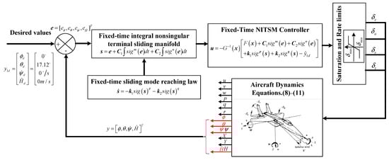
To offer a clearer summation of the control design procedure, a block diagram illustrating the control architecture is presented in Figure 1.
Figure 1.
The proposed fixed-time NITSM spin recovery control architecture.
Remark 2.
The variables highlighted in red in Figure 1 are regarded as the input states to design controller.
5. Discussions
To validate the efficacy and superiority of the proposed spin recovery controller, numerical simulations are conducted in this section using the F-18 HARV model. Parameter values are borrowed from [12]. The initial and final conditions for simulation are obtained from bifurcation analysis results. In Ref. [12], the spin solutions of the aircraft have been obtained by bifurcation analysis. As a result, the findings obtained from this analysis are not reiterated in the present paper. The initial and final reference points are listed in Table 1 and Table 2.

Table 1.
Initial and final state variables.
Table 2.
Initial and final control variables.
To evaluate the performance of the spin recovery control approach, we use the NDI and finite-time SMC spin recovery methods as comparative methods [12,18]. The simulations are conducted under two different initial spin values (oscillatory and steady).
Spin recovery control is attempted after 10 s of spin motion. During the first 10 s, the control inputs are held in the fixed position, referring to Table 2. Then, the control inputs in Equation (18) are applied at t = 10 s to converge the control variables to their desired states . The spin recovery simulation results are exhibited in Figure 2 and Figure 3, while the computed control commands are shown in Figure 4.
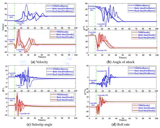
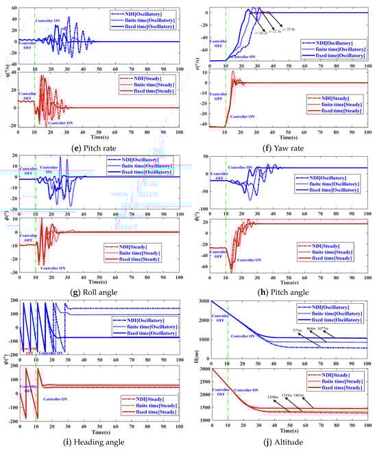
Figure 2.
System response under two different initial spin states.
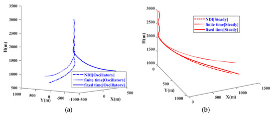
Figure 3.
Aircraft trajectory under two different (a,b) initial spin states.
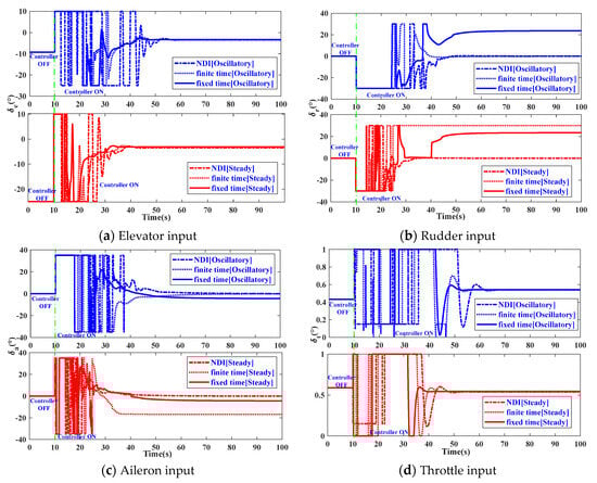
Figure 4.
Control commands under two different initial spin states.
It is apparent from Figure 2 that the proposed spin recovery controller can provide a faster convergence rate compared to NDI and the finite-time SM spin recovery control method. It can be observed that the convergence time for two initial conditions is very close to each other, indicating that the characteristic is independent of the initial conditions. It is observed from Figure 2g–i that the response curves of , , and can effectively track the desired values. For the oscillatory spin recovery, the and converge to the desired states at t = 28.92 s and t = 30.37 s, respectively. For the steady spin recovery, the and converge to the desired states at t = 23.51 s and t = 24.8 s, respectively. In the case of the oscillatory spin recovery, the aircraft spin rotation stops after completing 1.75 left turns at t = 23.35 s, as shown in Figure 2i. For the steady spin recovery, the aircraft spin rotation stops after completing 0.75 left turns at t = 14.01 s, as shown in Figure 2i. Thus, it is evident that the convergence time of is less than that of and , indicating that the aircraft spin rotation stops well before achieving level flight. More explicitly, achieves the desired altitude rate for oscillatory and steady spin recovery as shown in Figure 2j at H = 1077 m and H = 1463 m, respectively. As depicted in Figure 2j, the aircraft, subjected to two distinct spin motions, maintains a reference altitude of 3 km for 10 s, subsequently experiencing altitude losses of approximately 592 m and 677 m, respectively. The descent rates are approximately 59.2 m/s and 67.7 m/s, respectively. This indicates that aircraft require altitude margins of 1331 m and 860 m to reach the desired α, respectively. In conclusion, the proposed spin recovery controller mitigates the altitude loss compared to NDI spin recovery and the finite-time SMC method. This reduction is significant for avoiding ground collisions.
The control command curves are shown in Figure 4. The control inputs of elevator, aileron, rudder, and throttle are simultaneously applied at t = 10 s, and the control commands are constrained [17]. Figure 4 reveals that the controller is manipulating the surface downwards to reduce the , controlling the to restrain the yaw rotation, and employing in the roll direction to sustain a flight at a constant altitude. Additionally, it is evident that the aerodynamic control surfaces (, , , and ) exhibit a reduced time to withdraw from their permissible limits. To sum up, the superiority of the explored fixed-time spin recovery approach over finite time and NDI methods is clearly demonstrated through simulation results.
6. Conclusions
A novel fixed-time NITSM controller for spin recovery is exploited. Based on the conducted simulations, the proposed spin recovery controller demonstrates a superior convergence rate compared to NDI and finite-time SMC spin recovery schemes. Consequently, the aircraft can recover from spin motions in a shorter time with less altitude loss. The fixed-time NITSM spin recovery controller has exhibited satisfactory performance under two different initial spin conditions. This method of spin recovery is expected to render substantial aid in the evolution of upcoming technologies designed for automated spin recovery. Given that the saturation control problem represents a significant hindrance to minimizing convergence time, future research will aim to explore the allocation of control between aerodynamic surfaces and thrust vectors.
Author Contributions
Methodology, H.W.; validation, H.W.; investigation, H.W., Z.Z. and L.Y.; resources, H.W. and X.W.; writing—original draft preparation, H.W.; writing—review and editing, H.W., Z.Z. and Y.Y.; funding acquisition, Z.Z. All authors have read and agreed to the published version of the manuscript.
Funding
This study was supported by the National Natural Science Foundation of China (Grant No. 621733339).
Institutional Review Board Statement
Not applicable.
Informed Consent Statement
Not applicable.
Data Availability Statement
The data presented in this study are available on request from the corresponding author. The data are not publicly available due to privacy.
Conflicts of Interest
The authors declare no conflicts of interest.
Appendix A
Table A1.
System matrix elements.
Table A1.
System matrix elements.
| Symbol | Expansion Expression |
|---|---|
Table A2.
Control matrix elements.
Table A2.
Control matrix elements.
| Symbol | Expansion Expression | Symbol | Expansion Expression |
|---|---|---|---|
| 0 | 0 | ||
| 0 |
References
- Farcy, D.; Khrabrov, A.N.; Sidoryuk, M.E. Sensitivity of Spin Parameters to Uncertainties of the Aircraft Aerodynamic Model. J. Aircr. 2020, 57, 1–16. [Google Scholar] [CrossRef]
- Sidoryuk, M.E.; Khrabrov, A.N. Estimation of Regions of Attraction of Aircraft Spin Modes. J. Aircr. 2019, 56, 205–216. [Google Scholar] [CrossRef]
- Malik, B.; Masud, J.; Akhtar, S. A review of experimental techniques to predict aircraft spin and recovery characteristics. Aircr. Eng. Aerosp. Technol. 2022, 94, 187–197. [Google Scholar] [CrossRef]
- Malik, B.; Masud, J.; Akhtar, S. A Review and Historical Development of Analytical Techniques to Predict Aircraft Spin and Recovery Characteristics. Aircr. Eng. Aerosp. Technol. 2020. ahead-of-print. [Google Scholar] [CrossRef]
- Bunge, R.A.; Kroo, I.M. Automatic spin recovery with minimal altitude loss. In Proceedings of the 2018 AIAA Guidance, Navigation, and Control Conference, Kissimmee, FL, USA, 8–12 January 2018; pp. 1–22. [Google Scholar]
- Rao DM KK, V.; Sinha, N.K. A sliding mode controller for aircraft simulated entry into spin. Aerosp. Sci. Technol. 2013, 28, 154–163. [Google Scholar] [CrossRef]
- Khatri, A.K.; Singh, J.; Sinha, N.K. Aircraft Maneuver Design Using Bifurcation Analysis and Sliding Mode Control Techniques. J. Guid. Control Dyn. 2012, 35, 1435–1449. [Google Scholar] [CrossRef]
- Lee, D.C.; Nagati, M.G. Momentum Vector Control for Spin Recovery. J. Aircr. 2004, 41, 1414–1423. [Google Scholar] [CrossRef]
- Akhtar, S.; Malik, B.; Masud, J. Control Law Affect on Spin Characteristics of Aerodynamically Asymmetric Aircraft. In Proceedings of the AIAA Atmospheric Flight Mechanics Conference, Grapevine, TX, USA, 9–13 January 2017; American Institute of Aeronautics and Astronautics: Reston, VA, USA, 2017. [Google Scholar] [CrossRef]
- Kim, D.; Oh, G.; Seo, Y. Reinforcement Learning-Based Optimal Flat Spin Recovery for Unmanned Aerial Vehicle. J. Guid. Control Dyn. 2017, 40, 1074–1081. [Google Scholar] [CrossRef]
- Rao, D.M.K.K.V.; Go, T.H. Optimization of aircraft spin recovery maneuvers. Aerosp. Sci. Technol. 2019, 90, 222–232. [Google Scholar] [CrossRef]
- Raghavendra, P.; Sahai, T.; Kumar, P.A. Aircraft Spin Recovery, with and without Thrust Vectoring, Using Nonlinear Dynamic Inversion. J. Aircr. 2005, 42, 1492–1503. [Google Scholar] [CrossRef]
- Atesoglu, O.; Ozgoren, M.K. Control and Robustness Analysis for a High-alpha Maneuverable Thrust-Vectoring Fighter Aircraft. J. Guid. Control Dyn. 2009, 32, 1483–1496. [Google Scholar] [CrossRef]
- Feng, Y.; Yu, X.; Han, F. On nonsingular terminal sliding-mode control of nonlinear systems. Automatica 2013, 49, 1715–1722. [Google Scholar] [CrossRef]
- Rao, D.M.K.K.V.; Sinha, N.K. Aircraft Spin Recovery Using a Sliding-Mode Controller. J. Guid. Control Dyn. 2010, 33, 1675–1679. [Google Scholar] [CrossRef]
- Yu, S.; Yu, X.; Shirinzadeh, B. Continuous finite-time control for robotic manipulators with terminal sliding mode. Automatica 2005, 41, 1957–1964. [Google Scholar] [CrossRef]
- Salahudden, S.; Ghosh, A.K. Robust control design based aircraft flat-spin recovery using optimally deflected novel deployable fin. Aerosp. Sci. Technol. 2021, 115, 106823. [Google Scholar] [CrossRef]
- Salahudden, S.; Dwivedi, V.S.; Dwivedi, P.N. Aircraft flat-spin recovery using sliding-mode based attitude and altitude control. Proc. Inst. Mech. Eng. Part G J. Aerosp. Eng. 2021, 235, 924–936. [Google Scholar] [CrossRef]
- Salahudden, S.; Dwivedi, P.N.; Ghosh, A.K. Aircraft Spin Recovery with Altitude Loss Reduction Using Closed-Loop Thrust Control. In Proceedings of the AIAA SciTech Conference, Virtual, 11–15, 19–21 January 2021; pp. 1–11. [Google Scholar] [CrossRef]
- Salahudden, S.; Das, A.T.; Ghosh, A.K. Sliding-Mode Control and Strategic Thrust-Vectoring Based Aircraft Flat Spin Recovery with Altitude Loss Minimization. IEEE Trans. Aerosp. Electron. Syst. 2022, 58, 3271–3282. [Google Scholar] [CrossRef]
- Salahudden, S.; Sanwale, J.; Giri, D.K.; Ghosh, A.K. Aircraft Flat-Spin Recovery with Noisy Feedback Using Robust Control. In Proceedings of the AIAA AVIATION 2023 Forum, San Diego, CA, USA, 12–16 June 2023. [Google Scholar]
- Polyakov, A. Nonlinear feedback design for fixed-time stabilization of linear control systems. IEEE Trans. Automat. Control 2011, 57, 2106–2110. [Google Scholar] [CrossRef]
- Liu, K.; Wang, R.; Wang, X. Anti-saturation adaptive finite-time neural network based fault-tolerant tracking control for a quadrotor UAV with external disturbances. Aerosp. Sci. Technol. 2021, 115, 106790. [Google Scholar] [CrossRef]
- Tran, X.T.; Oh, H. A modified generic second order algorithm with fixed-time stability. ISA Trans. 2020, 109, 72–80. [Google Scholar] [CrossRef]
- Zuo, Z. Non-singular fixed-time terminal sliding mode control of nonlinear systems. IET Control. Theory Appl. 2014, 9, 545–552. [Google Scholar] [CrossRef]
- Yang, I.; Byun, S.; Seo, B. Robust Dynamic Inversion based on Sliding Mode Control for Autonomous Underwater Vehicles. IFAC Proc. Vol. 2013, 46, 79–84. [Google Scholar] [CrossRef]
- Shen, Q.; Yuan, S.; Zhu, H. Tracking and docking control of receiver aircraft based on robust dynamic inversion. In Proceedings of the IEEE Chinese Guidance, Navigation & Control Conference, Nanjing, China, 12–14 August 2016. [Google Scholar] [CrossRef]
- Wang, N.; Wu, H.N.; Guo, L. Coupling-observer-based nonlinear control for flexible air-breathing hypersonic vehicles. Nonlinear Dyn. 2014, 78, 2141–2159. [Google Scholar] [CrossRef]
- Liu, X.; Huang, W.; Du, L. An integrated guidance and control approach in three-dimensional space for hypersonic missile constrained by impact angles. ISA Trans. 2017, 66, 164–175. [Google Scholar] [CrossRef]
Disclaimer/Publisher’s Note: The statements, opinions and data contained in all publications are solely those of the individual author(s) and contributor(s) and not of MDPI and/or the editor(s). MDPI and/or the editor(s) disclaim responsibility for any injury to people or property resulting from any ideas, methods, instructions or products referred to in the content. |
© 2024 by the authors. Licensee MDPI, Basel, Switzerland. This article is an open access article distributed under the terms and conditions of the Creative Commons Attribution (CC BY) license (https://creativecommons.org/licenses/by/4.0/).