Abstract
This paper develops an analytical model to calculate the ultimate bearing capacity of the integrated plug high-strength geocell (IPGC)-reinforced foundation under a square footing. The high strength and stiffness of the geocell wall and the typical failure of the integrated plug-in joint tearing were considered. The ultimate bearing capacity of the IPGC-reinforced foundation was calculated in two separate parts. The ultimate bearing capacity of an unreinforced foundation was calculated using the modified Terzaghi equation. The increased bearing capacity of the IPGC was calculated as the function of the tearing force of the geocell wall, the height and the diameter of a geocell, the empirical static earth pressure coefficient, and the vertical additional stress coefficient under uniformly distributed rectangular loading. The results showed that the maximum error between the experimental and the theoretical results is less than 18%. The ultimate bearing capacity of IPGC-reinforced foundations decreases with larger geocell diameters. When the diameter of the geocell exceeds 1.8 times the foundation width, the confinement effect of IPGC becomes negligible. The findings of this study offer a robust analytical equation for predicting IPGC-reinforced foundations, along with valuable insights into the efficacy of IPGC reinforcement in enhancing foundation stability.
1. Introduction
The geocell, with its intricate three-dimensional honeycomb-like structure crafted from interconnected synthetic strips, serves as a robust solution for reinforcing foundations [1]. Within this structure, soil experiences heightened lateral stresses, effectively limiting the movement of soil particles and enhancing shear strength. The confinement provided by adjacent cells further bolsters resistance against external loads passively, aided by the geocell’s high hoop strength, which restricts lateral expansion (Figure 1) [2,3]. Such structural integrity, often established through methods like extrusion or adhesion, significantly mitigates the intrusion of base materials into soft soil foundations, thereby fortifying weakened substrates and minimizing settlement occurrences [4,5,6,7]. Consequently, the bearing capacity of geocell-reinforced foundations is intricately linked to factors like cell wall tensile strength, cell opening size, and joint characteristics [8,9,10,11].
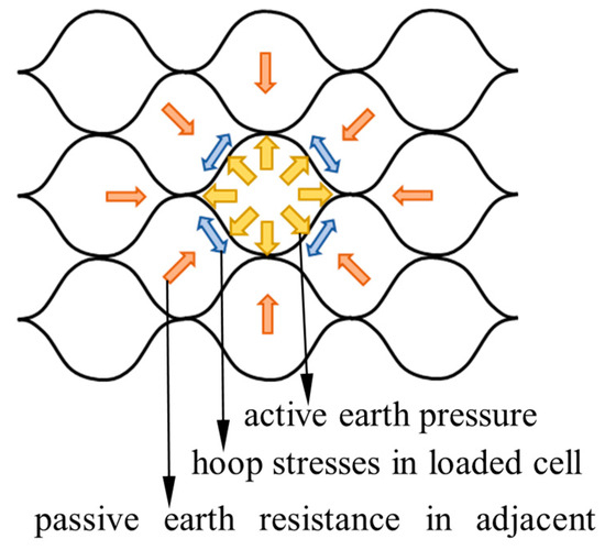
Figure 1.
Force distribution in the geocell.
The interlock-enhanced integral geocell (IPGC), as depicted in Figure 2, represents a notable advancement in high-strength geocell technology. The IPGC wall exhibits significantly higher strength in the horizontal direction than in the vertical direction. This discrepancy leads to stress concentrations at cut locations, increasing the likelihood of horizontal tearing. Consequently, such tearing can compromise the integrity of the overall connection points. The confining effect of the geosynthetic structure is limited by these connections, likely due to localized eccentric effects that occur under real-world conditions. In contrast to traditional counterparts, the IPGC wall is polypropylene, with a longitudinal tensile strength of ≥244 MPa, an elongation at break of ≤15%, and a tensile strength at the plug-in joint of ≥244 MPa. The thickness of the cell wall is (0.45 ± 0.1) mm, and the height is 50 mm. The integration of plug-in joints, formed by pins with a diameter of ≥2.5 mm inserted into geocell wall cuttings, further enhances its structural integrity. Both model tests [12] and finite element analysis [13] have underscored IPGC’s reliance on the high strength and stiffness of its geocell wall, which effectively confines the infill soil. Han et al. (2014) [12] and Dai et al. (2019) [14] conducted model experiments to compare the bearing capacity and deformation characteristics of sand foundations with those reinforced by IPGC under varying conditions. The schematic diagram of the IPGC-reinforced foundation under a square footing is presented in Figure 3. The scale ratio is about 1:12 for the testing application [12,15]. However, it is essential to note that additional tests and discussions on scale ratios are necessary if the results are to be applied to real projects. A square footing with a width of B is positioned in the center of the model box. Du is the top space of IPGC from the bottom of the footing. h is the height of the cell wall. d0 is the diameter of the maximum cell size. p is the overburden loading. The study found that foundations reinforced with IPGC have significantly higher initial stiffness and more than double the bearing capacity of foundations on a sand base.
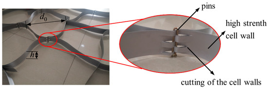
Figure 2.
Picture of IPGC (h is the height of the cell wall, and d0 is the diameter of the maximum cell size).
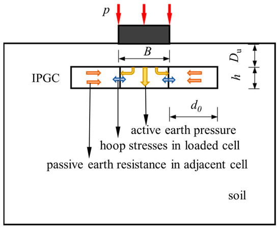
Figure 3.
The schematic diagram of the IPGC-reinforced foundation under a square footing.
Hou et al. (2024) [16] further analyzed the mechanism of IPGC-reinforced foundations using FEM3D (Abaqus, version 6.14). Referring to Dai et al. (2019) [14] and Hou et al. (2024) [16], the scale ratio is 1:1 for testing modeling in this study, which helps accurately simulate the stress and strain conditions, as illustrated in Figure 4. They investigated vertical displacement, horizontal displacement, stress distribution in the soil, and the tensile stress, friction, and contact force of the geocell wall. The results showed that the geocell reinforcement layer reduces horizontal and vertical displacements. The primary confinement of the geocell is due to the friction between the infill material and the geocell wall. The stiffness of the geocell contributes to a tensioned membrane effect and broader stress distribution, enhancing the performance of the soil foundation. Hou et al. [13,17] also found that geocells effectively prevent soil particle displacement under load due to their sidewalls. The 3D network structure with apertures permits soil particle penetration from one side of the cell to the other, thereby restraining lateral deformation and potential strain within the soil. Consequently, the applied load is distributed over a wider area, increasing the composite system’s shear strength and enhancing the foundation’s load-bearing capacity. Dai et al. (2019) [14] identified a critical failure mode wherein lateral tearing along the integrated plug-in joints can significantly diminish IPGC-reinforced foundation bearing capacity, as depicted in Figure 5. These model experiments and finite element simulations provide macroscopic and microscopic insights into the mechanism of IPGC in reinforced foundations, offering guidance for theoretical model development in this study.
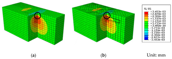
Figure 4.
Contours of horizontal displacement [15]: (a) unreinforced soil under the foundation footing and (b) reinforced soil under the foundation footing (The significant constraint caused by the geocell occurs at the top of the joint, shown as circles, while the dashed-line box indicates the IPGC).
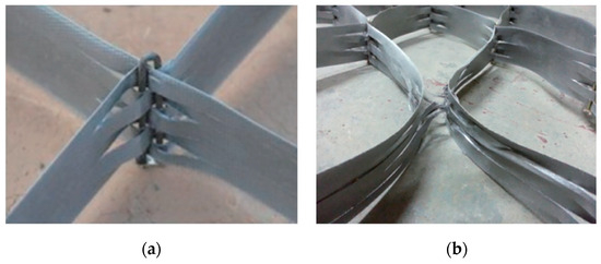
Figure 5.
Photographs of an IPGC joint [14]: (a) the plug-in joint before loading and (b) the plug-in joint after loading.
The soil suitability for good interaction in geocell applications depends on soil type, grain size, and cohesion. Gravel and crushed stone are excellent for their strength and drainage. Well-graded sand and sandy gravel offer good interlocking and support. Coarse-grained soils like coarse sand and gravel perform well due to their drainage and stability. Meanwhile, sand is ideal for geocell foundations due to its ease of compaction, effective load distribution, and minimal settlement. Its granular nature enhances load-bearing capacity, and it is readily available and cost-effective for large projects. Easy handling and installation ensure optimal geocell performance. These advantages are supported by various studies [1,3,5]. Therefore, sand was tested for using IPGC in the experimental study [12] and was also used to verify our calculation results in this study. However, the choice should align with project requirements, with soil analysis and geotechnical consultation ensuring optimal interaction.
Figure 6 presents the flow chart of the paper. The ultimate bearing capacity (pu) of an IPGC-reinforced foundation under a square footing was calculated separately: the ultimate bearing capacity (p0) of an unreinforced foundation and the bearing capacity increased by the IPGC (Δp). The modified Terzaghi equation, referring to Wang (2012) [18], was used to calculate the bearing capacity of unreinforced soil. It is the function of the cohesion of soil (c), the surcharge on two sides of the footing (q), the gravity of soil (γ), the width of a square footing (B), and the bearing capacity coefficient (Nc, Nq, Nγ). The increased bearing capacity of the IPGC was calculated as the function of the tearing force of the cell wall (F), the height of the cell wall (h), the diameter of the maximum cell size (d0), the empirical static earth pressure coefficient (K0), and the vertical additional stress coefficient under uniformly distributed rectangular loading (α).
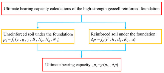
Figure 6.
Flow chart of the paper.
Despite the extensive use of experimental investigations in engineering, there is still a gap in understanding the theoretical analysis required to predict the bearing capacity of IPGC-reinforced foundations. This paper aims to bridge this gap by developing a theoretical model for designing the bearing capacity of an IPGC-reinforced foundation. The model meticulously accounts for the confinement effects resulting from the high strength and stiffness of the geocell wall and the typical failure modes associated with integrated plug-in joint tearing. By integrating theoretical frameworks with practical evaluations, this study offers valuable insights into the efficacy of IPGC reinforcement in enhancing foundation stability.
2. Methodology and Analytical Equation
2.1. Ultimate Bearing Capacity of Unreinforced Foundation under a Square Footing
The ultimate bearing capacity (p0) of an unreinforced foundation under a square footing can be calculated based on the modified Terzaghi theory, referring to Wang (2012) [18], as follows:
where c is the cohesion of soil, q is the surcharge on two sides of the footing, γ is the gravity of soil, Nc, Nq, Nγ are the bearing capacity coefficients, which can be determined as follows:
where φ is the internal friction angle of the soil.
2.2. Enhancement of Ultimate Bearing Capacity by the IPGC
2.2.1. The Relationship between Vertical and Horizontal Stress of Soil in a Cell
The cell walls of IPGC have high tensile strength and stiffness. The experimental results showed that the maximum tensile strain of the cell wall was only 0.5% when the IPGC-reinforced foundation failed [12]. Therefore, the lateral movement of soil particles can be hypothesized as completely restricted. The stress of the infill soil element in a cell then has the following relationship [18]:
where σx and σy are stress in the x and y lateral directions, respectively. σz is the vertical stress of soil under overburden loading (p), and K0 is the empirical static earth pressure coefficient.
Referring to Michalowski et al. (2005) [19], the empirical static earth pressure coefficient, which is widely used in engineering, can be calculated as follows:
2.2.2. The Relationship between the Overburden Loading and the Vertical Stress of the Soil
The additional stress induced by the overburden loading (p) at each corner of the rectangular base can be calculated by the Boussinesq equation as follows:
where α is the vertical additional stress coefficient under uniformly distributed rectangular loading, l is the width of the long side of the rectangular, b is the width of the short side of the rectangular, and Du is the top space of IPGC from the bottom of the footing.
2.2.3. The Relationship between Hoop Stress and Cell Wall Tearing Strength of the IPGC
The tearing force (F) of the cell wall can be calculated as follows:
where t and σt are the thickness and the linear elastic tensile stress of the cell wall, respectively, and h is the height of the cell wall.
Due to the high stiffness and low strain of the cell wall, the stress distribution is considered uniform during loading. Consequently, the cell is assumed to be circular in theoretical calculations for computational simplicity. The stress of a single cell under an overburden loading can be calculated by the theory of thin-walled rings in the linear elastic range, as depicted in Figure 7. Although this approach may introduce some discrepancies between theoretical values and experimental results, it aids in establishing a foundational understanding of IPGC performance. This understanding can serve as a basis for more extensive analyses in subsequent investigations.
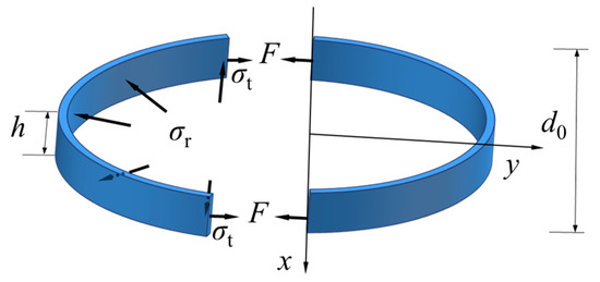
Figure 7.
Stress distribution in a cell.
Considering the symmetry, the tearing force of the cell wall (F) can be calculated as follows:
where σr is the lateral confinement stress of the cell induced by the movement of soil particles, and d0 is the diameter of the maximum cell size.
Considering the circle shape of a cell, the following equation can also be obtained:
From Equations (10) and (11), the following equation can be obtained:
Three tensile tests were conducted to measure the strength of the cell wall and plug-in joints, as depicted in Figure 8. It is worth noting that the samples were not filled with soil during the test. The results indicated minimal variation among the three sets of tests, demonstrating good consistency. The peak tensile strength standard deviation for the tested samples was 2.6 MPa. Figure 8a displays the photographs and stress–strain curve of the cell wall, while Figure 8b illustrates the photographs and stress–strain curve of geocell joints after tension tests. Figure 8a shows that the stress–strain relationship of the cell wall remains linear within the 10% strain range. Meanwhile, from Figure 8b, when the stress is 32.5 MPa (see point A in Figure 8b), the cell wall at the pin plug-in joint begins to tear significantly (see comparison from the dotted line box to the solid line box in Figure 8b). In the model experiments, it was observed that the bearing capacity of the foundation could be significantly diminished, resulting in rapid failure when tearing occurs along the integrated plug-in joint of the cell wall laterally [14]. Therefore, the overburden loading corresponding to the tearing strength of the cutting cell wall at the plug-in joint of the IPGC can represent the cell wall’s tearing force (F). According to Equations (5), (7) and (12), the bearing capacity increase by the cell directly below the foundation of IPGC (Δp) can be expressed as follows:
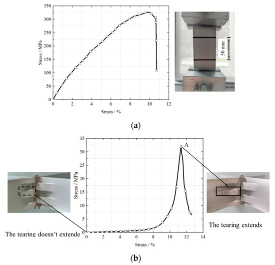
Figure 8.
Photographs and stress–strain curves of the cell wall and plug-in joints in tensile tests: (a) photograph and stress–strain curve of cell and (b) photograph and stress–strain curve of IPGC at the plug-in joint.
Confinement from adjacent cells provides additional resistance against the loaded cell through passive resistance, while the lateral expansion of the infill restricted by high hoop strength should also be considered:
where n is the number of cells, and i is the ith cell.
The possibility of the superposition of the load-bearing capacity of geocells and the soil contained in them is supported by several mechanisms: the joint action between the basement structure and internal soil [12], the reinforcement effect of the soil [14], their mutual interaction [16], and existing research findings [7,20,21,22]. By combining the ultimate bearing capacity of an unreinforced foundation and the increased bearing capacity of the IPGC, the ultimate bearing capacity of IPGC-reinforced foundation (pu) can be expressed as follows:
According to Equations (1), (14) and (15),
Meanwhile, various studies have shown that the ultimate bearing capacity of a reinforced foundation is affected by the top space of the reinforced layer [3,12,13,23]. Figure 9 illustrates the relationship between the influence coefficient of the top space (β) and the top space of IPGC from the bottom of the footing in the experiments [24]. The published experimental data [12] were used to validate the calculations from the theoretical model. A single linear model with a coefficient of determination (R2) = 0.96 was fitted to all data in Figure 9. Using the fitting method, the influence coefficient of the top space (β) can be obtained as follows:
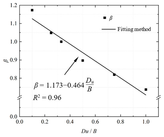
Figure 9.
Relationship between the influence coefficient of the top space and the top space of IPGC from the bottom of the footing in the experiments.
Therefore, the ultimate bearing capacity of a multilayer IPGC-reinforced foundation can be calculated as follows:
3. Results and Discussion
The data from model tests [12], as depicted in Table 1, are utilized to compare the results obtained from the developed theoretical model. An example of the calculation process can be found in Appendix A. The minimum and maximum errors observed are 9% and 18%, respectively. The data from the model tests conducted by Shadmand et al. (2018) [25] are also provided in Table 1 for comparative analysis. The errors observed are 15%. Therefore, the developed theoretical model reasonably accurately calculates the bearing capacity of traditionally IPGC-reinforced foundations.

Table 1.
Comparison between the model tests and the theoretical equation.
Figure 10 further illustrates the effect of the diameter of the maximum cell size (d0) on the ultimate bearing capacity (pu) of an IPGC-reinforced foundation under a square footing using the proposed analytical model. It can be observed that the ultimate bearing capacity of the IPGC-reinforced foundation decreases with the increase in cell diameter. When d0 is more significant than 1.8B, the confinement of IPGC can be neglected. The ultimate bearing capacity is similar to those of the unreinforced foundation (295 kPa in Han et al., 2014 [12]), indicating that the shear plane occurred inside a cell of the IPGC, resulting in a local failure of the foundation.
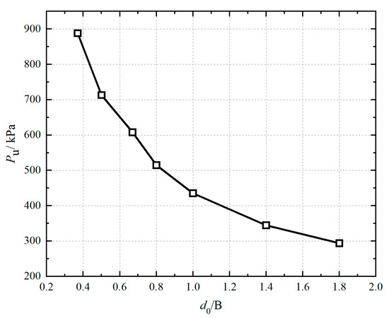
Figure 10.
The ultimate bearing capacity of IPGC-reinforced foundation under different d0.
4. Conclusions
This study has developed a theoretical model to predict the ultimate bearing capacity of IPGC-reinforced foundations under square footings. By considering the geocell wall’s high strength and stiffness and the typical failure mode of integrated plug-in joint tearing, the model provides a comprehensive approach to estimating foundation stability. The main results are as follows:
- The calculated values from the theoretical model align well with experimental data, with a maximum error of 18%. It was observed that the reinforcement effect of IPGC may be disregarded when the top space exceeds the footing width.
- When the cell diameter surpasses 1.8 times the foundation width, the confinement effect of IPGC becomes negligible, resulting in an ultimate bearing capacity similar to that of unreinforced foundations.
- It is essential to note that additional tests and discussions on scale ratios are necessary if the results are to be applied to real projects. Meanwhile, further comparative studies involving various foundation reinforcement technologies and soils are required to fully assess the effectiveness of IPGC compared to other solutions available on the market.
Author Contributions
Conceptualization, J.H.; Methodology, J.H., X.H. and S.L.; Data curation writing original draft preparation, J.H. and X.H.; Writing—review and editing, J.H.; Visualization, Y.M.; Project administration, J.H. All authors have read and agreed to the published version of the manuscript.
Funding
This study has been supported by the National Natural Science Foundation of China (NSFC) (Nos. 51978390, 51778353), 2023 Basic Research Program of Qinghai Province (2023-ZJ-756), and China Scholarship Council (CSC 201906895014).
Institutional Review Board Statement
Not applicable.
Informed Consent Statement
Not applicable.
Data Availability Statement
The original contributions presented in the study are included in the article; further inquiries can be directed to the corresponding author.
Conflicts of Interest
The authors declare no conflicts of interest.
Nomenclature
| B | the width of the square footing; |
| b | the width of the short side of the rectangular; |
| c | the cohesion of soil; |
| Du | the top space of IPGC from the bottom of the footing; |
| d0 | the diameter of the cell; |
| F | the tearing force of the cell wall; |
| h | the height of the cell wall; |
| i | the ith cell; |
| K0 | empirical static earth pressure coefficient; |
| l | the width of the long side of the rectangular; |
| Nc, Nq, Nγ | the bearing capacity coefficient; |
| n | the number of cells; |
| p | the overburden loading; |
| pu | the ultimate bearing capacity of an IPGC-reinforced foundation under a square footing; |
| p0 | the ultimate bearing capacity of an unreinforced foundation; |
| Δp | the bearing capacity increased by the IPGC; |
| q | the surcharge beside two sides of the footing; |
| t | the thickness of the cell wall; |
| α | the vertical additional stress coefficient under uniformly distributed rectangular loading; |
| γ | the gravity of soil; |
| β | the influence coefficient of the top space; |
| φ | the internal friction angle of the soil; |
| σx, σy | stress in the x and y lateral directions, respectively; |
| σz | the vertical stress of soil under overburden loading p; |
| σt | the linear elastic tensile stress of the cell wall; |
| σr | the lateral confinement of the cell induced by the movement of soil particles. |
Appendix A. An Example of the Calculation Process
In the model test [12], the width B of the square foundation is 0.3 m, and dry sand was used (c = 0). The linear elastic tensile stress of the cell wall, denoted as σt, can be determined through the tensile test described in Figure 8a. The top space of the foundation is 0 m, and the internal friction angle φ of the soil is 35.43°.
According to Equations (2)–(4), the following can be obtained:
When the internal friction angle of the soil is 35.43°, according to Equation (6), the following can be obtained:
When the top space of IPGC from the bottom of the footing (Du) is 0.33B, according to Equation (1), the calculation equation of Terzaghi foundation bearing capacity under rectangular footing can be obtained:
In the cell directly below the foundation slab, according to Equation (8) and the corner-points method, the vertical additional stress coefficient α under uniformly distributed rectangular loading is:
According to Figure 9 and Equation (14), the bearing capacity increase by the IPGC is:
According to Equation (17), the influence coefficient of the top space β is:
Therefore, according to Equation (18), the ultimate bearing capacity of an IPGC-reinforced foundation is:
References
- Hegde, A.; Sitharam, T.G. 3-Dimensional numerical modelling of geocell reinforced sand beds. Geotext. Geomembr. 2015, 43, 171–181. [Google Scholar] [CrossRef]
- Hegde, A. Geocell reinforced foundation beds-past findings, present trends and future prospects: A state-of-the-art review. Constr. Build. Mater. 2017, 154, 658–674. [Google Scholar] [CrossRef]
- Dash, S.K.; Krishnaswamy, N.R.; Rajagopal, K. Bearing capacity of strip footings supported on geocell-reinforced sand. Geotext. Geomembr. 2001, 19, 235–256. [Google Scholar] [CrossRef]
- Pokharel, S.K.; Han, J.; Leshchinsky, D.; Parsons, R.; Halahmi, I. Investigation of factors influencing behavior of single geocell-reinforced bases under static loading. Geotext. Geomembr. 2010, 28, 570–578. [Google Scholar] [CrossRef]
- Tafreshi, S.M.; Dawson, A.R. Comparison of bearing capacity of a strip footing on the sand with geocell and with planar forms of geotextile reinforcement. Geotext. Geomembr. 2010, 28, 72–81. [Google Scholar] [CrossRef]
- Avesani Neto, J.O.; Bueno, B.S.; Futai, M.M. A bearing capacity calculation method for soil reinforced with a geocell. Geosynth. Int. 2013, 20, 129–142. [Google Scholar] [CrossRef]
- Tafreshi, S.N.M.; Shaghaghi, T.; Mehrjardi, G.T.; Dawson, A.R.; Ghadrdan, M. A simplified method for predicting the settlement of circular footings on multi-layered geocell-reinforced non-cohesive soils. Geotext. Geomembr. 2015, 43, 332–344. [Google Scholar] [CrossRef]
- Sireesh, S.; Sitharam, T.G.; Dash, S.K. Bearing capacity of circular footing on geocell-sand mattress overlying clay bed with void. Geotext. Geomembr. 2009, 27, 89–98. [Google Scholar] [CrossRef]
- Zhao, M.H.; Chen, B.C.; Yin, B.P.; Hu, Z. Model tests on bearing capacity characteristics of geocell gravel base and rigid pavement. Chin. J. Geotech. Eng. 2012, 34, 577–581. [Google Scholar]
- Zhao, M.H.; Long, J.; Zhang, L.; Ma, B.H.; He, L.P. Comparative analysis of model tests on different types of composite foundations. Chin. J. Geotech. Eng. 2013, 44, 611–618. [Google Scholar]
- Latha, G.M.; Somwanshi, A. Effect of reinforcement form on the bearing capacity of square footings on sand. Geotext. Geomembr. 2009, 27, 409–422. [Google Scholar] [CrossRef]
- Han, X.; Zhang, M.X.; Li, J.Y.; Jiang, S.W. Model test of IEI reinforced sand foundation. J. Yangtze River Sci. Res. Inst. 2014, 31, 27–33. [Google Scholar] [CrossRef]
- Hou, J.; Zhang, M.X.; Han, X.; Li, R. Mechanism of a IEI using FEM. Chin. J. Geotech. Eng. 2015, 37, 26–30. [Google Scholar] [CrossRef]
- Dai, Z.H.; Zhang, M.X.; Hou, J.; Li, J.Z. Experimental comparative study of new lock enhanced integral geocell and geogrid mesh elements reinforced foundation. J. Shanghai Univ. (Nat. Sci.) 2019, 25, 796–806. [Google Scholar] [CrossRef]
- Sun, Z.; Zhang, M.X.; Jiang, S.W. Model tests on sand embankment reinforced with geocell subjected to strip loading. Chin. J. Geotech. Eng. 2015, 37, 170–175. [Google Scholar] [CrossRef]
- Hou, J.; Chu, C.X.; Lu, X.Q.; Xing, X. FEM3D analysis of interlock-enhanced integral geocell-reinforced foundation. Soil Mech. Found. Eng. 2024, in press. [Google Scholar]
- Hou, J.; Liu, S.T.; Lu, X.Q.; Karen, M. Simulation of geocell-reinforced foundation using particle flow code. IOP Conf. Ser. Earth Environ. Sci. 2021, 861, 032069. [Google Scholar] [CrossRef]
- Wang, C.H. Soil Mechanics; China Architecture & Building Press: Beijing, China, 2012. [Google Scholar]
- Michalowski, R.L.; Asce, F. Coefficient of earth pressure at rest. J. Geotech. Geoenviron. Eng. 2005, 133, 1429–1433. [Google Scholar] [CrossRef]
- Hirai, H. Settlements and stresses of multi-layered grounds and improved grounds by equivalent elastic method. Int. J. Numer. Anal. Methods Geomech. 2008, 32, 523–557. [Google Scholar] [CrossRef]
- Vakili, J. A simplified method for evaluation of pavement layers moduli using surface deflection data. In Proceedings of the 12th International Conference of International Association for Computer Methods and Advances in Geomechanics (IACMAG), Goa, India, 1–6 October 2008; Volume 16, pp. 4314–4319. [Google Scholar]
- Fu, Z.Q.; Wang, G.Y.; Hou, D.Y.; Che, Q. Study on bearing capacity of rectangular foundations supported on geogrid reinforced sand. J. Shandong Univ. (Eng. Sci.) 2003, 60, 61–62+68. [Google Scholar]
- Dash, S.K. Influence of relative density of soil on performance of geocell-reinforced sand foundations. J. Mater. Civ. Eng. 2010, 22, 533–538. [Google Scholar] [CrossRef]
- Hou, J.; Zhang, M.X.; Dai, Z.H.; Li, J.Z.; Zeng, F.F. Bearing capacity of strip foundations in horizontal-vertical reinforced soils. Geotext. Geomembr. 2017, 45, 29–34. [Google Scholar] [CrossRef]
- Shadmand, A.; Ghazavi, M.; Ganjian, N. Load-settlement characteristics of large-scale square footing on sand reinforced with opening geocell reinforcement. Geotext. Geomembr. 2018, 46, 319–326. [Google Scholar] [CrossRef]
Disclaimer/Publisher’s Note: The statements, opinions and data contained in all publications are solely those of the individual author(s) and contributor(s) and not of MDPI and/or the editor(s). MDPI and/or the editor(s) disclaim responsibility for any injury to people or property resulting from any ideas, methods, instructions or products referred to in the content. |
© 2024 by the authors. Licensee MDPI, Basel, Switzerland. This article is an open access article distributed under the terms and conditions of the Creative Commons Attribution (CC BY) license (https://creativecommons.org/licenses/by/4.0/).