Article

Cloud-Based Architecture for Production Information Exchange in European Micro-Factory Context

by
Fábio M-Oliveira
1,*,
André Dionísio Rocha
1,
Duarte Alemão
1,
Nelson Freitas
1,
Rayko Toshev
2,
Jani Södergård
2,
Nikolaos Tsoniotis
3,
Charalampos Argyriou
3,
Alexios Papacharalampopoulos
4,
Panagiotis Stavropoulos
4,
Pietro Perlo
5 and
José Barata
1
1
NOVA School of Science and Technology, Center of Technology and Systems (UNINOVA-CTS) and Associated Lab of Intelligent Systems (LASI), NOVA University Lisbon, 2829-516 Lisbon, Portugal
2
School of Technology and Innovations, Industrial Management, Vaasa University of Applied Sciences, Wolffintie 30, 65200 Vaasa, Finland
3
IDEAS FORWARD PC, 78 Georgiou Papandreou, 54655 Thessaloniki, Greece
4
Laboratory for Manufacturing Systems and Automation (LMS), Department of Mechanical Engineering and Aeronautics, University of Patras, Rion, 26504 Patras, Greece
5
Interactive Fully Electrical Vehicles (I-FEVS), Strada Carignano 50/1, La Loggia, 10040 Torino, Italy
*
Author to whom correspondence should be addressed.
Appl. Sci. 2023, 13(18), 10223; https://doi.org/10.3390/app131810223
Submission received: 13 July 2023 / Revised: 1 September 2023 / Accepted: 8 September 2023 / Published: 12 September 2023
(This article belongs to the Special Issue Smart Manufacturing and Industry 4.0, 2nd Edition)

Abstract

:
In a constantly changing world, information stands as one of the most valuable assets for a manufacturing site. However, exchanging information is not a straightforward process among factories, and concerns regarding the trustability and validation of transactions between various stakeholders have emerged within the context of micro-factories. This work presents an architecture designed to enable information exchange among heterogeneous stakeholders, taking advantage of the cloud infrastructure. It was designed to enable the use of several tools, connected through a middleware system deployed on the cloud. To demonstrate the potential of this architecture, a platform was instantiated, and two use cases—designed to accurately represent real manufacturing sites—were implemented.

1. Introduction

In the recent past, both industrial and academic researchers have driven the usually called fourth industrial revolution (I4.0) to respond to market demand for personalized and customized products [1]. This movement is empowered in Europe by the German Electrical and Electronic Manufacturers’ Association (ZVEI). Concepts such as interoperability, cyber-physical systems, cloud computing, or blockchain are now usual when we are talking about Information and Communication Technologies (ICT) applied to manufacturing, both when we talk about the factory shop floor or the supply chains and even when the focus is the after-sales support. These concepts trigger new business models targeting decentralized manufacturing, augmenting manufacturing efficiency, and upholding operational excellence within environmental care.
This work aims to present a software architecture capable of providing a fully integrated cloud-based ecosystem, merging the best practices and lessons learned from the past, and linking existing technologies of existing tools with emergent technologies such as blockchain, artificial intelligence, and big data analytics, among others. As part of these efforts, a blockchain architecture will also be developed to support decentralization and increase trust among the different partners providing traceability over operational boundaries and seamless interoperability regardless of the interfaces or tools used.
This work is focused and oriented to industrial use cases, trying to cover as much as possible of the European industrial force.
Besides the architecture, this work presents an integrated cloud platform to demonstrate the concept, from end to end, starting with the client creating a purchase order passing through the Enterprise Eesource Planning (ERP), to the Manufacturing Execution System (MES), until the delivery of the purchased product. The data models used for this integrated cloud platform will be described to demonstrate the data flow, synchronization, and interoperability between all software parts and systems and the hardware used on the shop floor. The integration of blockchain technology to validate some of the transactions between partners and to assure authenticity will also be depicted in this work.

1.1. Motivation

Several companies related to micro-factories were taken into account during the design process to understand the functionalities that this architecture should be compliant with. One of the major features required was the guarantee of trustability and traceability of data that flow between actors and the use of cloud technologies as enablers. Another highlighted functionality was the ability to analyze the performance not only locally at the shop-floor level but on several processes performed by different companies. Due to the nature of the micro-factories, modularity on such kinds of platforms is also a requirement; different clients have different needs, and at some points in time, it can be a necessity to enable the contribution of different stakeholders. For instance, a micro-factory producing plastic components might have to contract an external entity to make LCA assessments for one particular product for a specific client, and to do so, it cannot invest in a new infrastructure that will be used only on one small fraction of the production. Some works focus on information exchange such as [2], where some adoption barriers are identified such as trust, security, data control, and availability of resources but seem restricted to the manufacturing process and the collaborative networks paradigm. In [3], an information exchange architecture is presented with a web application as a mediator. The approach depends on specific integration libraries and the import and export of files through the web interface. From our analyses, it lacks scalability features and does not take advantage of the cloud paradigm. Also, trustability is not addressed in this architecture since it relies on the mutual trust of the organizations. Focusing on the particular issues of the automotive industry, in [4], another architecture for information exchange is presented. The implementation is based on a publish/subscribe mechanism, and the information is exchanged with JSON files. However, there is no mechanism to include external companies to exchange or validate the trustability of information flow that is focused on tracking machine data and mapping that information during the manufacturing process. A smart factory information service bus is presented in [5] with a focus on applications for several stakeholders, but it lacks an explanation of how the different actors can communicate with each other. Although this work seems complete, it does not have the trustability capacities to validate the message exchange and also does not highlight how it can be used in a cloud environment.
From our research, there is no software architecture integrated with the cloud ecosystem that focuses on the information exchange between several stakeholders, that is modular, scalable, and trustable.

1.2. Definitions

Manufacturing sites are innovation sites since there are a lot of challenges to optimizing product throughput. New approaches like Cyber-Physical Systems (CPS) and Cyber-Physical Production Systems (CPPS), Cloud Computing (CC) and Manufacturing (CM), Internet of Things (IoT), blockchain, and big data analytics, which are related to embedded systems and systems of systems, help to face the increase in globalization in a manufacturing context. With these technologies, it is possible to increase flexibility and competitiveness, quality, and efficiency principally for Small and Medium-sized Enterprises (SMEs).
This sub-section explains core concepts, such as CPS and CPPS, the definition of cloud-based systems, including CC and CM, and finally the conjunction between CC, CM, and Cloud-based CPPS. A highlight of the Industry 4.0 is also covered here.

1.2.1. Industry 4.0 Concept

The I4.0, an initiative by the German federal government, represents a way to add value to the product life cycle. It strongly relies on ICT and the smart manufacturing concept, which means that production systems are adaptable and flexible, adjusting automatically to different production processes and products and reacting to changing environments on supply and demand [6]. I4.0 can be defined in three dimensions: horizontal integration across the value chain, end-to-end engineering, and vertical integration of manufacturing systems [7] to enhance mass customization [8]. The I4.0 concept is enabled by several technologies such as big data, cloud, IOT, simulation, augmented reality, additive manufacturing, autonomous robots, and horizontal and vertical system integration [9].

1.2.2. CPS and CPPS

The fourth industrial revolution is only possible with the advantage of the so-called CPS. CPS can be described as the integration between the digital and physical worlds. It consists of a control unit, sensors, and actuators. The control unit, usually implemented with one or several microcontrollers, receives data from the sensors, which can get information about the surrounding environment and controls actuators interacting with the real world. CPS opens the possibility for manufacturing systems to monitor physical processes in real time and make intelligent decisions through cooperation with humans, machines, sensors, etc. During the past years, the focus of attention was directed to this subject due to the evolution of the following [10]: (a) sensing systems that allow precise monitoring of the system; (b) communication technologies that provide high speed and low latency on data exchange, both on wired and wireless communications; (c) computer processing power that enables the process and analyses of large amounts of data at an affording cost; (d) cognition systems, which are systems that bring together machines and humans, giving more human-like behaviors to machines; and (e) autonomous control that emphasizes the reaction of the system without direct human intervention.
According to C. Liu and Jiang [11], a suitable CPS architecture for shop-floor intelligent manufacturing should include three layers, as demonstrated in Figure 1. Each CPS can autonomously collect and send data as well as send and receive information as needed. The three layers identified are a physical connection layer, a middleware layer, and a computation layer.
Physical connection layer: This layer deals with collecting and transmitting data from operations. Sensors and other measurement devices gather the information at a low level and distribute it through the production environment. These components should be chosen considering the operational constraints such as protocols, processing, location, distance, and storage. On the shop floor, groups of machines are typically connected through fieldbus technology and/or industrial Ethernet.
Middleware layer: This layer is intended to transfer the collected data from the embedded components to a more powerful device, to be analyzed, and to send commands to the production from the computation layer or other external applications. This layer deals with the reception of data and information in variable data formats, depending on the brand and type of the embedded component, and translates the production commands from the computational layer (or external applications) into commands that can be triggered by the shop-floor machines.
Computational layer: In this layer, models, algorithms, and tools are developed to analyze and extract patterns from the raw data received from the embedded devices and sensors. Also, data can be received from other software tools, namely ERP, MES, and Supply Chain Management (SCM). With all these data, it is possible to have a better insight into machine working conditions, product and sub-product quality, manufacturing processes, etc. In this layer, two kinds of big data computing need to be provided: stream computing, to process near-real-time raw shop-floor data, and batch computing, to process large volumes of historical data. With this combination, and with human inputs, it is possible to create a unified view of information and knowledge that supports intelligent decision making to control processes and operations, and execute maintenance on the shop floor.
CPPSs are, like CPSs, recognized as one of the keys to unlocking the potential benefits of Industry 4.0 as they enable enterprises to evolve into this industrial revolution. CPPS is performed when all CPSs are connected to a production system. It can be described as a system able to autonomously exchange information, controlling and actuating independently on its own components, smart machines, storage systems, and production facilities. CPPS can accelerate improvements not only in the industrial processes but also in product engineering, supply management, material usage, and life cycle management [12].

1.2.3. Cloud Computing

Cloud Computing (CC) has a disruptive business approach that enables the customers to pay for resources that they actually use and need instead of embarking on a sizable initial investment in hardware and specialized human resources to install it. Technology giants such as Google, Amazon, or Microsoft build and manage their own cloud infrastructure and provide resources to third-party companies with a usage-based pricing model. In this kind of ecosystem, there can be intermediary service providers that provide their services, renting resources to the cloud infrastructure providers. With this in consideration, CC creates new opportunities for companies, especially for small and medium-sized enterprises by offering higher performance at a lower cost, high scalability, availability, and accessibility, reducing business risks and big upfront investments and maintenance expenses [13].
As a base foundation for the implementation of a CC system, an architecture is necessary as a guide. Usually, it is based on a four-layer structure, namely: a hardware/data center layer, infrastructure layer, platform layer, and application layer [14].
According to Figure 2, there are three standard service models: Infrastructure as a Service (IaaS), Platform as a Service (PaaS), and Software as a Service (SaaS). According to L. Wang [13], these services are suitable for IT professionals (IaaS), developers (PassS), and business end-users (SaaS). Access to these services is provided through standard interfaces namely WebServices, Service-Oriented Architecture (SOA), or Representational State Transfer (REST) services.
Different service levels require different knowledge and effort from different stakeholders. Figure 3 depicts the several layers and typical interventions between the user and service provider.
On the left side of Figure 3, the user manages all activities. The responsibility in managing systems decreases when using other service levels. In the IaaS paradigm, the user manages the five top layers. In PaaS, the user is only responsible for the two top layers, and when using Saas, the user has no intervention in any of these layers, as it is the responsibility of the service provider.
CC can have several models, depending on the requirements of the end-users: they can be public, private, community, or hybrid [15]. The restrictions of access will be tightly aligned with the business process, type of information, and level of vision desired. A public cloud platform, as the name suggests, is used when manufacturing resources are shared with the general public. Companies and partners can publish or request data and services from the cloud platform. This kind of cloud is open to all parties but does not expose all the information. An example can be an email service such as Gmail from Alphabet, which is freely accessible, but each customer can only use or access their quote upon login. A private cloud is built to be accessible only from a single organization, to share resources among different subsidiaries of the enterprise. Although typically more expensive than the public clouds, they are more secure and manage the privacy of the organization more efficiently. The hybrid cloud is a combination of public and private clouds merging the best features from both approaches. The community cloud is a deployment model that is used for sharing resources between several organizations. As an example, cooperation among universities on a research topic can be supported by a community cloud [13,16].

1.2.4. Cloud Manufacturing

Due to the success of CC with the business model of pay-as-you-go services, a new concept directly emerged, Cloud Manufacturing (CM). CM is a paradigm that will revolutionize the manufacturing industry with highly collaborative and innovative manufacturing-service-oriented production. The most important feature of CM is the easiness and convenience of sharing a variety of different types of distributed manufacturing resources. This vision is known as Manufacturing as a Service (MaaS) [13].
According to Wu et al. [17], a CM architecture is composed of ten layers (Figure 4) in which seven functional layers of the architecture are facilitated by the three layers of knowledge, cloud security, and network.
Resource layer: Composed of manufacturing resources and abilities that can be distributed across several different providers.
Perception layer: Using IoT, it senses the manufacturing resources and provides a connection to the CM platform enabling communication and interactions between a cloud platform and the physical devices.
Virtualization layer: Encapsulates into Manufacturing Cloud Services (MCS) the manufacturing resources and abilities, by virtualizing these items, enabling access to service-oriented technologies and CC technologies.
Core Cloud Service Layer: Sometimes referred to as core middleware, it provides two categories of service: the MCS and the Cloud Manufacturing core services (CMfg). MCS is the result of the encapsulation of manufacturing resources and abilities that can be invoked by end-users. CMfg are the main services provided to manage, access, and invoke MCS for three category users (provider, operator, and consumer).
Application layer: Contains applications according to specific demands such as cooperative management systems, cloud-manufacturing-based ERP, etc.
Portal layer: Provides human–machine interaction for user access.
Enterprise cooperation application layer: Includes commerce, business, and manufacturing cooperation.
Knowledge layer: Provides the knowledge needed for the seven functional layers described above.
Cloud security layer: Provides mechanisms and strategies specifically for CM system security.
Network: Also referred to as the communication layer, it provides communication support for users, operations, resources, services, etc., in CM systems.
CM can only be fully deployed with the contributions of other emergent technologies such as IoT, CPS, CC, Semantic Web Technology, Service-oriented technology, Virtualization, High-performance computing, System Management Technologies, Big Data analytics, Cybersecurity Mesh, Zero Trust, and others related to security.
CM can be one of the new solutions for the challenges that manufacturing environments face since it provides tools for resource sharing and the use of globally distributed, scalable, sustainable, and service-oriented manufacturing systems.

1.2.5. Cloud-Based CPPS

The cloud-based concept has now some applications in different sectors such as agriculture, food processing, automotive industry, machinery and tool industry, semiconductor industry, environmental monitoring, and security surveillance, among others. The interest in integrating cloud resources into CPSs has increased in recent years, which reflects the emergence of new fields like Cloud Robotics, Sensor Clouds, and Vehicular Clouds [18].
Nowadays CPSs are implemented as small nodes incorporated in larger systems. These nodes have limited computing capabilities and low storage available, but almost always, they have some kind of network interface. With the rise of IoT and CC, several new perspectives have appeared for those CPSs, to extend their resources by taking advantage of cloud resources [18,19]. In Industry 4.0, CPS is one of the main technologies and usually is connected through the Internet. Recently, the concept of cloud was applied to CPS resulting in cyber manufacturing. Using real-time connectivity on the connection between physical machines and by using CC, cyber manufacturing is capable of realizing true-sense CPS with multiple functions in one closed loop. Cloud-based cyber manufacturing can be described as an integrated CPS that can provide on-demand manufacturing services, digitally or physically using efficient manufacturing resources distributed across several locations [13].
According to Chaâri et al. [18], there are three core requirements for cloud-based CPS: offloading intensive computation; storing and analyzing large amounts of data; and seamless access through virtual interfaces. Knowing these requirements, CC represents a possible suitable solution since it addresses all of these three challenges. When CPS is used with a high-bandwidth connection, CC can provide both storage and computing resources to back-end CPS and allows easier integration of CPS by virtualizing access to them through Web Services Interfaces.
A cloud-based CPPS is, in fact, an extension of a CPS: it includes a flexible stack of CC services taking advantage of the computing power, storage, and software services in a scalable and cost-effective way. Cloud-based CPPS can support and improve manufacturing processes since it provides new capabilities for data collection, storage, analysis, and transmission.
Figure 5 shows a comparison of conventional, web-based, and cloud-based robot cells.
In a conventional robot cell, the application and service modules, control system, and physical components are locally integrated. Also, in this integration, all the data and knowledge remain. In a web-based robot cell, the physical system is independent of the control system and is operated remotely over the network. Information, services, and control are deployed in remote servers. This approach has some technical drawbacks since some issues can arise, such as difficult synchronizations, loss of real-time control, and/or stability risks. A hybrid solution is proposed with the cloud-based robot cell that balances the need for heavy computing and real-time local control. Data sharing, processing, and analyses can be performed remotely in the cloud, and physical applications can be created and maintained in virtual cloud services [20].
Some works with the use of cloud-based systems in conjunction with manufacturing challenges such as increasing product quality and decreasing production costs can be found in the literature. Some examples are as follows:
-
Gherardi et al. in 2014 suggested a PaaS approach for reconfigurable product lines based on cloud robotic applications. With this approach, end-users do not need to worry about low-level decisions when a line is reconfigured since the configuration of the robot is managed at a different level on the distributed system to the robot level in the cloud level [21];
-
Shu et al. in 2016 proposed a cloud-based CPS to provide flexible applications and services in the context of industrial applications and included virtualized resource management techniques, scheduling of resources, and Life Cycle Management (LCM) [22];
-
Lai et al. in 2018 proposed a task-scheduling algorithm for cloud-based CPS [19];
-
Keung et al. in 2020 provided a comprehensive understanding of how warehouses can be optimized by reducing the conflicts under multi-layer, multi-deep circumstances using IoT-aided applications and Wireless Sensor Networks (WSN) in conjunction with a cloud-based CPS [23].

2. Materials and Methods

2.1. Functional Design and Components of the Cloud-Based CPPS Architecture

Several initiatives during the past years addressed manufacturing optimization, but most of them aimed to run the software locally and very tightly aligned with specific factory ecosystems. Optimizing production capacity, quality control, or energy consumption by themselves without considering interoperability between the several stakeholders misses the full purpose of Industry 4.0. The architecture put forth by our work amplifies the principles of vertical and horizontal integration while also elevating the concept of end-to-end product integration and engineering:
Vertical integration: to integrate and interoperate all software tools and hardware inside a factory;
Horizontal integration: with the capacity to enable the interoperation of all the actors that contribute to the value chain, not only the suppliers, transporters, and factories but also the product itself;
End-to-end product integration and engineering: with the capacity to know or track the product and sub-product information along the life cycle.
The integration of all available information at these different levels allows the cloud-based cyber-physical ecosystem to coordinate activities, optimize the system as a whole, and generate more knowledge that previously was not available.
Using energy consumption as an example, several works such as openMOS [24] and PERFoRM [25] presented solutions to have some feedback of consumption on machines, transporters, or products but they did not present a globally optimal solution (only local solutions to each component). Complex system optimization, with several actors, requires distributed tools and a full view of the entire value chain.
With the cloud-based tools now available and in conjunction with new architectures such as the ones previously presented, it is possible to create an advanced ICT solution for monitoring and optimizing complex environments at different levels and granularities.
Using an ecosystem like the one presented in Figure 6, it is not yet straightforward how to optimize it.
This ecosystem can be easily divided into two big levels: the cloud and the factory levels.
At a factory level, nowadays, information is already collected by the production processes, and data are generated and gathered by the integrated sensors at the different line modules, or data are manually input by the plant workers into their internal systems. These data can be extracted and made available for all software tools inside the factory or at the cloud level (if some service is used subscribing for data updates for instance). With these up-to-date data, different tools can share information and knowledge about the processes and work together smoothly. This allows optimization at different levels and with different purposes and targets (optimization of the production process, quality control, energy consumption, etc.). If we divide and separate correctly what should be running locally and remotely, it will bring flexibility and adaptability for different users. Some tools require real-time control, and those time-critical activities must be deployed inside the factory; in other cases, it is more profitable to run the tools at a cloud level, where resources are virtually infinite.
When we look closely, the factory and its energy problems are only one of the nodes in a very complex and interconnected system. Perhaps the locally optimal solution is not the global optimal solution. That is why there is a need to consider cloud-based computing power when dealing with all the constraints along the value chain. The value chain is constituted of a complex flow of tasks and actions performed by several actors (suppliers, logistics, factories, or customers). There is a need to try to use a cloud-level solution on which all the different actors can deploy or retrieve data, with processing power to create knowledge and information that can be useful for finding global optimization for the system.
At a cloud level, it is possible to generate and track environmental footprints for each activity and stakeholder, store transactions among actors, and other features. A life cycle assessment (LCA) can be performed on the product, in each stage of its life, and even models of the behavior of the consumers can be achieved. Although polemic, this can be very important to reduce energy consumption by changing customers’ behavior and redesigning products as well as improving the quality of the products to match the consumers’ expectations based on their feedback.

2.2. Platform

This work proposes an architecture to implement a customizable cloud-based platform that can be used in different complex manufacturing environments, such as the one shown in Figure 6, and be instantiated in different cloud providers. The platform should be capable of interoperating different tools at different complexity levels and should be divided into two big groups of functionalities, one group that runs on the local shop floor and another intended to be running at the cloud level (Figure 7).
Shop-floor level: Within the factory, an integration layer will be deployed capable of connecting all the hardware (sensors, machines, stations, etc.) and existing software tools (MES, SCADA, etc.) with new tools capable of dealing with new functionalities and the integration with the cloud level.
Cloud level: The cloud level of the platform is responsible for receiving and storing all the data from the different actors of the system (factories, suppliers, transporters, customers, products, etc.) and allowing the integration of software tools, enabling macro-level optimization, such as the energy footprint of products, resource allocation, etc.
This platform aims to represent vertical integration and horizontal integration. As a requirement for this, the architecture for this platform should include middleware inside each factory that is responsible for vertical integration, enables the integration of any type of software tool (MES, data analytics, simulation, etc.), and uses the defined standard interfaces. The data generated by one tool should be available to be consulted by any other tool, with these tools being present at the launch of the system or added afterward. For instance, a new scheduling optimizer tool could be coupled with a traditional scheduling tool but with the ability to read the maintenance logs from a machine, use it as a Key Performance Indicator (KPI), and allocate resources based on the maintenance prediction for that specific machine. Even if not present at launch, this new tool should be able to be deployed and connected without any intervention on the platform.
The middleware should also be responsible for storing the current system state and keeping it available to the cloud tools if they require it on a publish/subscribe basis.
The cloud level of this platform will be responsible for connecting different factory middleware systems and other actors within the value chain. This service-oriented approach allows easy, scalable, and adaptable solutions that can be easily customized and deployed across different cloud providers.
The security of the information flowing on the platform should be performed through a secure mechanism such as blockchain technology. An added mechanism for tracking and tracing the flow of information should also be available.
This platform is designed to be applied to micro-factories, to tackle the challenges mentioned before by I4.0. In the beginning, most of the micro-factories focused on downscaling manufacturing systems to produce micro-products [26]. However, the concept of micro-factories refers to a reconfigurable and modular green manufacturing system that consists of compact and highly mobile facilities with small dimensions and high precision to respond to flexibility requirements [26,27,28]. Because of the small scale and flexibility in the mechanical structure, micro-factories can provide many benefits and increase the effectiveness of the manufacturing industry.
With this kind of platform, and the accessibility of the information, it is possible to apply dynamic pricing of the products, by sharing the micro-factories’ net workload and precisely tracking the carbon footprint for each item used as raw materials for supplying the micro-factories. Regarding the supply chain, this platform opens the door for a circular economy where suppliers that recycle materials can be chosen as priorities. At this time, it is very difficult for the client to make an environmentally friendly choice when a product is bought.
As important as it is to know how a product environment impacts production, it is also important to understand the impact over time. That is why in the design phase, the platform included the ability to integrate one or more LCA tools, with special attention to the additive manufacturing environmental impact [29].
This platform can be used as a tool to achieve the European Green Deal [30] which is an initiative with a focus on the EU being climate-neutral by 2050. The use of the authentic data exchanged, validated by one or more mechanisms, when flowing on the platform, can be used as a way to trace and optimize the resources applied in all steps, from the purchase until the delivery of the product. Figure 8 is an adaptation from the work of “Industry 4.0: The future of productivity and growth in manufacturing industries” [31], and it highlights which points this platform is demonstrated to work.
The architecture proposed, by design, can accommodate the eight topics depicted in Figure 8. During the development of the proof of concept and instantiation of the platform, only the topics on the right side of the picture were implemented and actively used. Nevertheless, in an easy way, tools that enable augmented reality, especially on the shop floor, could be created and connected to the platform. On the topic of additive manufacturing, data about the process and how it can be optimized, not only in quality but also in new types of materials, can be exchanged between different stakeholders. Regarding autonomous robots, the architecture can be used to exchange traffic and relative positions to optimize routes, and this information could be exchanged using the proposed platform. On the simulation topic, using the information that can be exchanged, simulations of the overhaul behavior of the systems can be performed. Regarding big data, tools can be connected to the platform to generate new knowledge from the raw data that are constantly being generated by the stakeholders. All of these uses of data need to have the agreement and the right permissions from each and every actor of the system.

2.3. Infrastructure and Functional Components

The platform for which this architecture was developed is rather complex, with several levels and components. Some of those components will be briefly exposed to contextualize the reader with the challenges.

2.3.1. Trustability and Traceability

The information flowing through the platform must be encrypted and validated on each transaction between the peers because the information is supposed to flow in every direction to be accessible for all authorized companies and between all of the software tools (that require it). For instance, one order can be sent directly from the client to the manufacturing facility, passing through several actors, and each of them must accept and validate the order. All of these paths must be validated, registered, and auditable by external tools to guarantee that the procedures performed during the manufacturing of the product or sub-product are compliant with all the restrictions that were agreed upon, for instance, on the use of recycled materials or water and energy consumption.

2.3.2. Enterprise Resource Planning

The ERP system is commonly understood as a set of comprehensive software used to manage business information and operations, especially in the manufacturing industry. The ERP system can be used to manage and integrate all the business functions within an organization. In essence, the ERP system is an essential component of manufacturing systems and is considered the backbone of Industry 4.0 [32]. For a standardized industry like manufacturing and production factories, this collection of software cuts across functions and tools for managing different aspects of the entire organization such as sales and distribution, material management, financial and cost accounting, human resources, production planning, and computer integrated manufacturing, supply chain, and so on [33,34,35].
These sets/collections of comprehensive software can facilitate the smooth flow of information between various functions, departments, and company processes (internal and external) within an organization. As a result, an efficient adoption and usage of ERP systems for both short and long-term operations of a company will contribute to successful organizational performance and survival in the face of unpredictable and disruptive innovations. When an ERP system is efficiently utilized by a company, the organization can achieve an improved performance level of the supply chain network and a reduction in cycle times [36,37].
ERP systems such as SAP, IQMS, Oracle ERP Cloud, Acumatica, Syspro, Sage, and so on have developed different modules and integrated functional software that covers key areas of manufacturing processes and operations such as supply chain, finance, human resources, customer relationship management, production, maintenance planning and execution, and so on (more about the different software can be accessed at https://www.selecthub.com/manufacturing-software/ (accessed on 7 September 2023)).

2.3.3. Life Cycle Assessment

LCA provides information to decision makers by giving insights into the potential environmental impact of products from raw material extraction or manufacture to end-of-life disposal. LCA, therefore, supports decision making by exposing trade-offs, illuminating system interactions, and showing impact over the whole product life cycle and not a specific phase.
LCA has been standardized by the International Organization for Standardization (ISO), and it is part of a family of concepts and tools that are being used by organizations to better understand, manage, and reduce the impacts of materials, products, and services across their life cycle.
The ISO standards 14,040 and 14,044 (International Organization for Standardization, 2006) define LCA as follows:
“LCA is the compilation and evaluation of the inputs, outputs, and the potential environmental impacts of a product system throughout its life cycle.”
[38]
There are three primary aspects or dimensions to a life cycle study:
  • Consideration of the life cycle stages for the product system in question: The life cycle is the physical sequence of operations in a product system. The primary stages are material acquisition and processing, product manufacturing, use, and end-of-life disposal/recycling.
  • Consideration of multiple environmental and resource issues across the life cycle stages: LCA studies trade-offs by analyzing significant inputs from the earth, the flow of these materials and energy carriers through the system, and outputs to the environment, across the various life cycle stages.
  • Assessment or interpretation of the significance of the results about the goal and scope of the study: The intended application of the study is critical for interpreting the results. For example, comparing the carbon footprint of one material to another requires more rigorous analysis and review than a study aimed at identifying the environmental and resource use hotspots in a system.

2.3.4. Manufacturing Execution System

MESs are used in manufacturing to track the evolution of raw materials until they become finished products. In this way, it can help the decision makers to analyze in real time the current scenario on the shop floor and act to improve the production process.
With new technologies emerging, MES allows the development of the Industrial Internet of Things (IIoT) environment, where all components may be connected and may interact with each other, from the low level within the factory to the higher level of analysis tools. It builds the bridge between the planning system (ERP, LCA, etc.) and the control system (PLC, SCADA, etc.), as shown in Figure 9. However, it needs to be designed to facilitate the integration of legacy systems to be compliant with Industry 4.0 technologies.
The inclusion of MES in the platform will allow better access to information about the production, improve quickness in decision making, reduce both production time and costs, detect failures in time to correct them, improve the quality of the final product, increase consumer satisfaction, and more. This can be achieved through digitization, which allows adapting the manufacturing systems to I4.0 and new technologies such as IoT and AI.
The functional layers of MES should be as follows:
Production parameterization: includes version control, production rules, bills of material, and resources, focused on defining how to manufacture the product.
Management of resources: focuses on registration and analysis of resource information, aiming to prepare and execute production orders with the right and available resources.
Production planning: determines the production schedule to meet the production requirements received from the ERP (or a specialized scheduling system).
Production execution: checks resources to inform other sub-systems regarding the production progress.
Production traceability: tracks the process information to have a complete sequence of lots, orders, and equipment.

3. Results

After the platform presentation, in this section, the architecture is explained, and two use cases that validate the aforementioned approach are presented.

3.1. Architecture

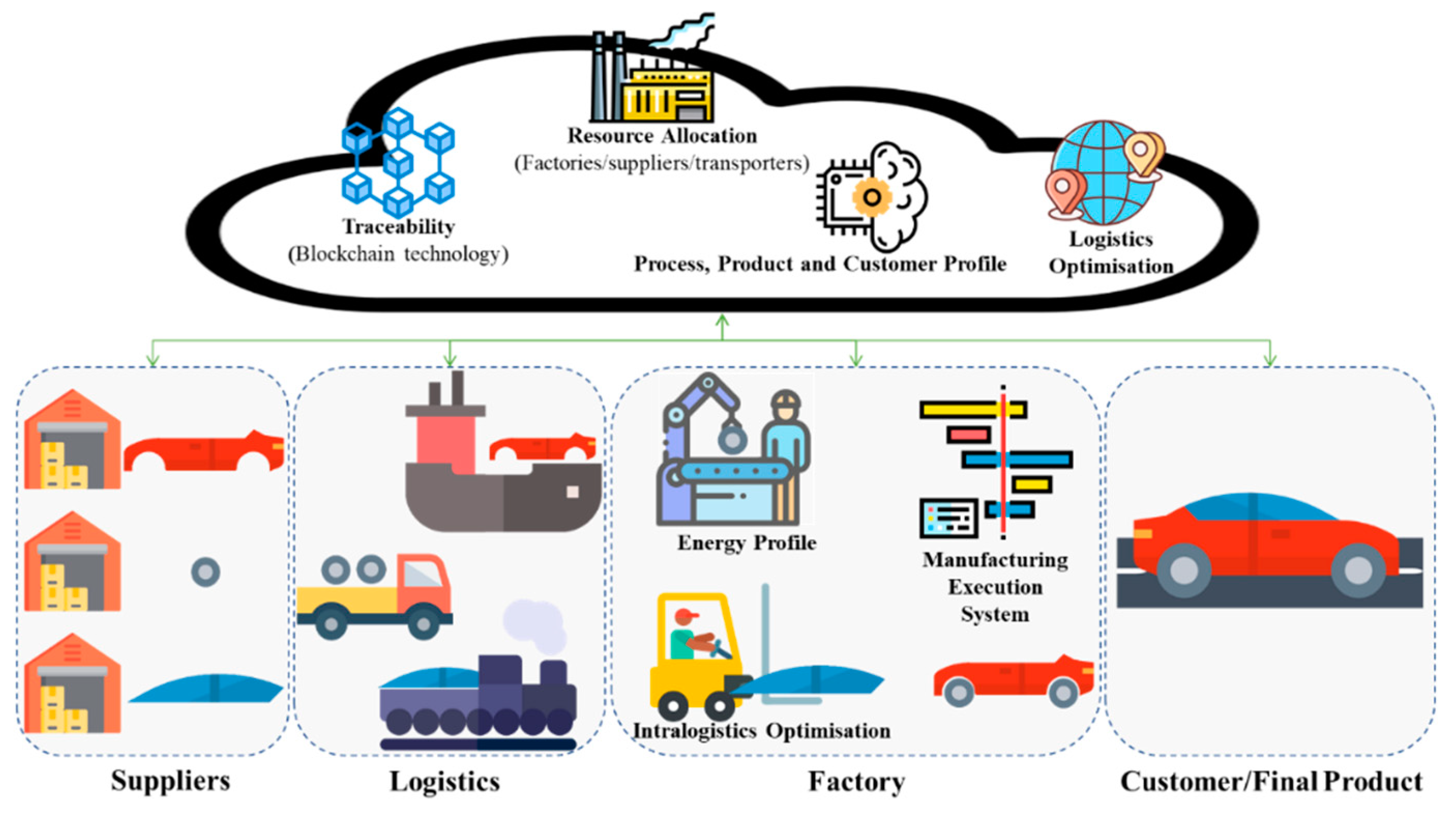
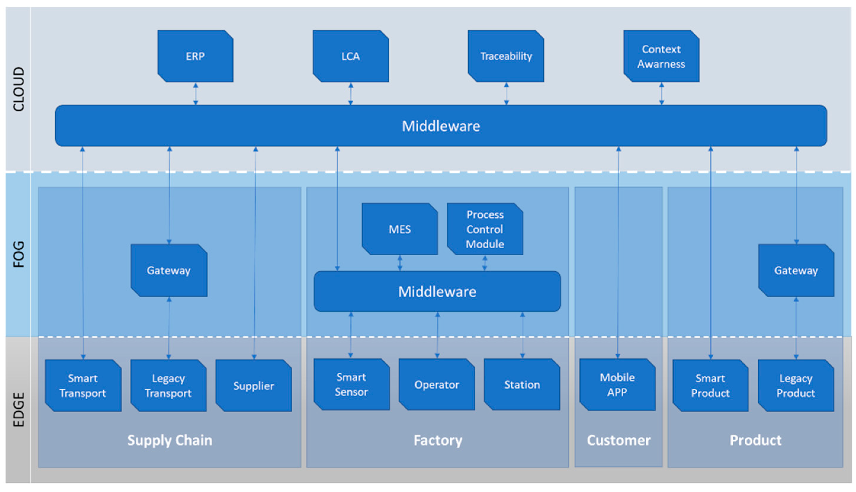
The proposed architecture consists in five main elements that will communicate with each other, namely the cloud middleware, the supply chain, the smart factory, the customer, and the product, as shown in Figure 10. The middleware hosted in the cloud will be the mutual point of interaction. Thus, all the other elements need to reach the cloud to share and exchange data, information, orders, and so on.
In this way, each component needs to expose its functionalities to the others to be reachable. Thus, this architecture will follow a service-based approach, which means that all the components of the architecture will expose its functionalities as services, making them available for the other components, and then be able to establish communication with the different components and systems. These services will be exposed through standard interfaces that are the point of interconnection between two systems or sub-systems in a transparent way.
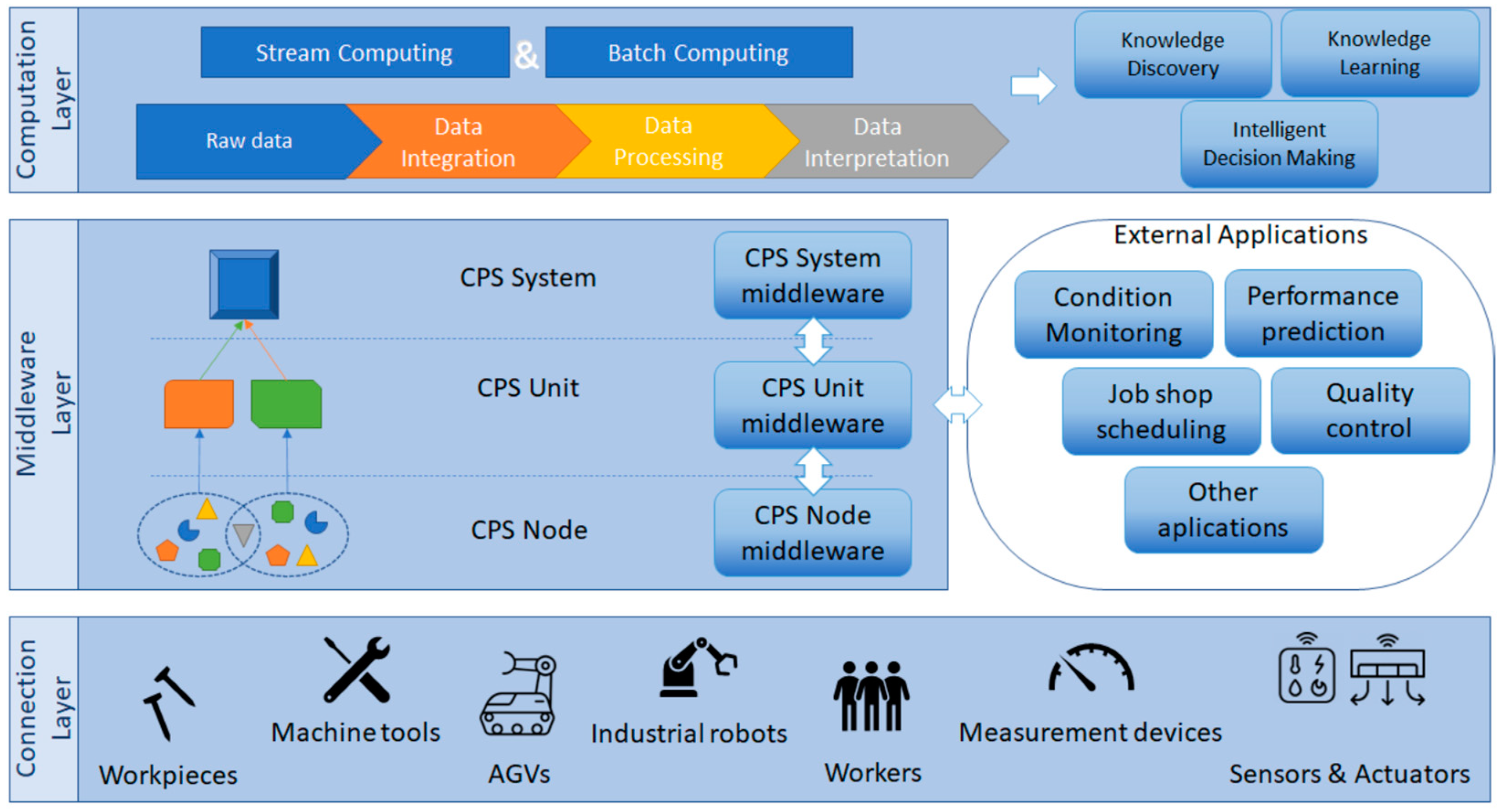
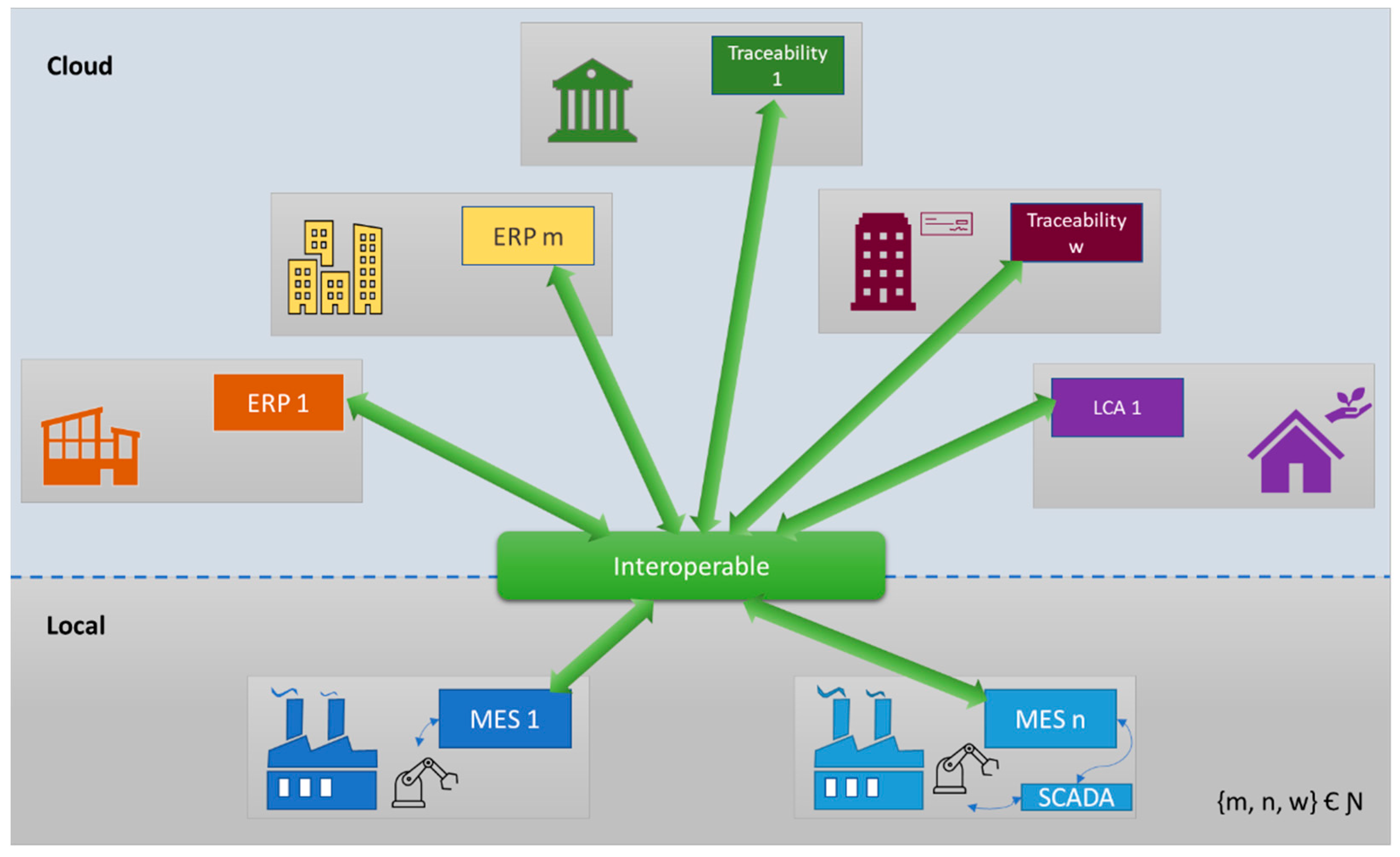
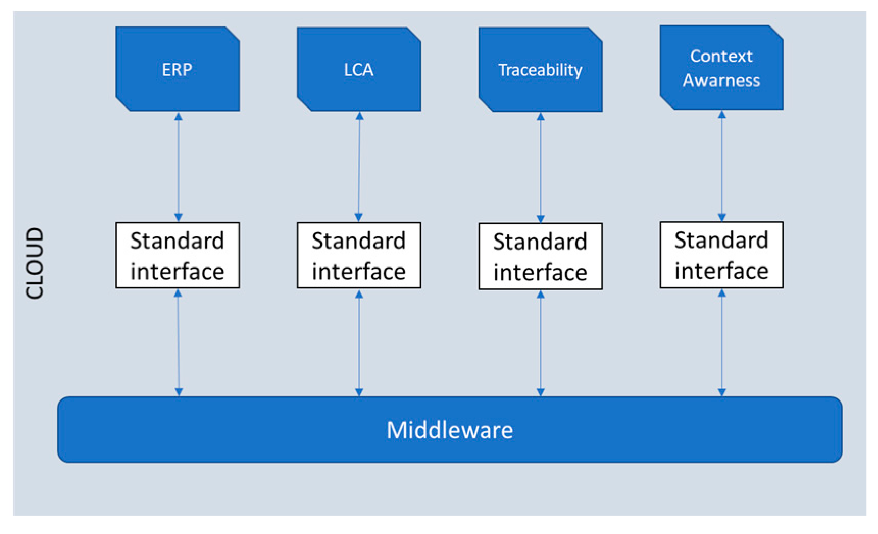
The main components of the system, as well as their inner components, will interact with each other through the system’s cloud middleware (Figure 11), where all the data and information will be stored, available, and updated continuously or periodically, depending on the type of data. The elements will not interact directly with each other, rather they will interact with the common middleware to reach the other elements. The cloud system will ensure that even if an element is down, its latest information will still be available to the remaining elements. Both vertical, i.e., integration and interoperation of all software tools and hardware inside the factory, and horizontal, i.e., capacity to interoperate all the actors that contribute to the value chain, such as suppliers, factories, and the product itself, communication should be supported by the cloud middleware.
The middleware works as a system or software component that is used to connect different applications or systems. The objective is to create communication between applications without them having to know about each other’s state and with minimum knowledge about the network connection [39]. Middleware systems have been more adopted lately since vast quantities of systems with different responsibilities are involved and must work cooperatively to keep the production in the good direction, from sensors and actuators on the shop floors to management systems for ERP.
This architecture presents two middleware systems, the one in the cloud and the one in the factory, that will provide a service registry, Yellow Page structure, that stores the diverse services available in the system.
The distributed and cloud approach that handles the interconnection of the elements by following service-oriented principles will avoid limitations for scalability, as well as problems related to single points of failure.
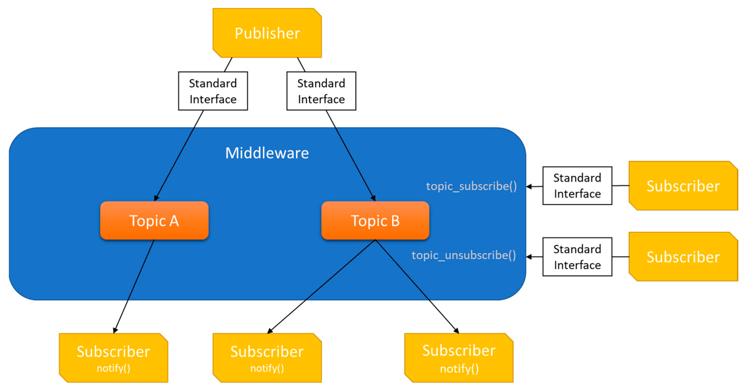
Both middleware systems, the one on the cloud and the one internal to the factory, will work with a publish-subscribe model. This model enables an application to announce events to multiple consumers by asynchronously broadcasting messages to different parts of the system.
Our approach considers that each component that sends data to the cloud or to be consumed by other entities is a publisher. A component that reads messages from a specific topic is a subscriber. The same entity or software can be a publisher and a subscriber at the same time. Typically, a publisher translates changes in the system or action into event messages, using a generic message format. Those messages are then published into specific topics in the middleware through a standard interface. The subscribers are notified that a new message is available on the topics that they are subscribed to. Figure 12 exemplifies this pattern.
A publish/subscribe model is an effective way to decouple sub-systems and manage communications between them, independently. Thus, this model avoids blocking sub-systems to wait for responses and quickly return to their main processing responsibilities, increasing the scalability and responsiveness of the overall system.
Moreover, this model offers improved reliability under increased loads, handles recurrent failures more effectively, and provides a straightforward integration between systems using different platforms, programming languages, or communication protocols, as well as between factory systems and cloud applications.
By design, publish/subscribe methods can guarantee some security features such as only delivering messages to registered and authenticated clients and can also retain some messages in case of any failure of the clients. The resilience of the communication channel can also be ensured with load distribution between the server nodes and high availability methods implemented by the publish/subscribe mechanism that ensures, besides availability, scalability.
The publish/subscribe methods that the middleware is implemented with are agnostic to the programming languages that send or receive the messages. This enables interoperability between stack holders by design.
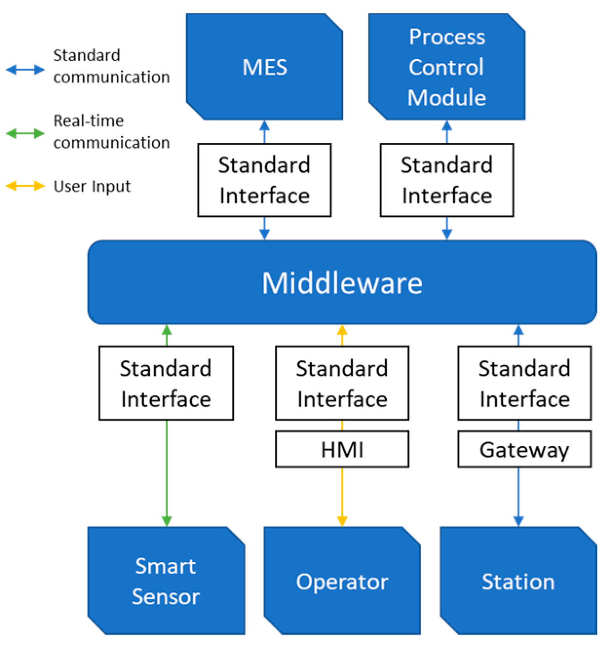
In our work, we present the use of two middleware systems, independent from each other because, at the shop floor, it is usually common to have legacy elements such as machines, working stations, and some sensors that may not be able to communicate directly to the cloud, either by their constraints or because of internal policies from the manufacturing companies. Human operators can input data to the cloud using a Human Machine Interface (HMI) that can write to this middleware, and then the message is translated into the cloud middleware. Machines can use their actual MES system with their actual metrics or use a specific gateway to translate the messages to the middleware on the shop floor, and the messages are forwarded to the cloud gateway. Figure 13 shows these approaches.
Both middleware systems, the one in the cloud and the one in the factory, will then communicate through a standard communication protocol to update and access each other’s information.
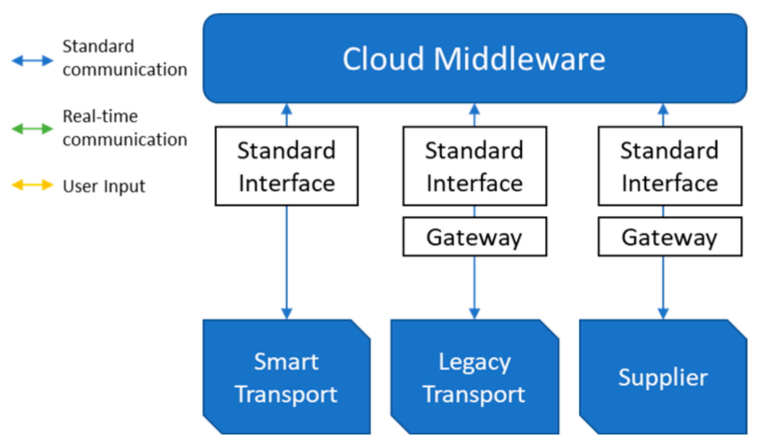
In the same way that some shop-floor machines can require a gateway to translate messages to the shop-floor middleware, other stakeholders may also need a gateway to translate their information to the cloud middleware, to send and receive messages that will be used in a standard way. Figure 14 shows an example of a supply chain element that uses this approach. “Smart Transport” and “Legacy Transport” can be routed from raw material suppliers or routes of sub-assemblies between factories or even final products.
This example from Figure 14 can also be applied to other elements such as products. In this example only standard communication is used. A legacy product can need a gateway to convert the legacy data to the standard communication from this platform. A legacy product is a product that was not designed to use these functionalities and/or does not have ways to communicate in a standard way. For instance, a brand-new car can be considered legacy if its configuration does not have a module to automatically connect to the platform. If the final user wants to use the functionalities from the platform, they can afterward acquire a gateway to send and receive the information from and to the platform.

3.2. Data Models

One of the biggest challenges of I4.0 is interoperability in real industrial systems. There are still a lot of difficulties in dealing with the representation and exchange of data coming from different entities and from different operating levels [41]. Our goal is to have full interaction of hardware resources, such as working stations and robots, and software applications, such as ERP, MES, or databases, from end to end in a bi-directional way. To have an architecture accepted by the industry, it is crucial to connect and integrate legacy systems.
Following this line of thought, the adoption of standard interfaces as the core drivers for pluggability and interoperability will contribute to enabling the interaction between hardware devices and software applications transparently. The standard interfaces should support devices, tools, and applications in order to fully expose and define their services in an exclusive, standardized, and clear way to increase the whole interoperability. These standard interfaces should provide a set of common functionalities:
  • The definition of the list of services to be implemented by the interface.
  • The description of each service (name, input, and output parameters).
  • The definition of the data model handled by the services.
From the point of view of the overall system, the standard interface abstracts the fundamental functions, making transparent the way the different components interact and operate. Additionally, a key requirement for the development of standard interfaces is the usage of service orientation to expose the corresponding devices and applications’ functionalities as services.
Nevertheless, to integrate legacy devices and systems, with their data models and specific requirements, it is necessary to allow the translation of legacy data into a uniform representation. To do so, it is necessary to add gateways as a middleman that will translate the legacy data and allow those devices and systems to have additional intelligence and be integrated into the CPS paradigm.

3.3. Technologies and Implementation

The architecture proposed needed to be validated, and, to do so, a set of technologies and some implementation details were chosen.

3.3.1. Communication at the Integration Layer

The primary objective of the integration layer is to facilitate the trade and flow of information from one system to another system that benefits from the data. This process can be, for example, a machine sending its data to an optimization software that generates new knowledge and new inputs that then flow in the opposite direction to the machinery, optimizing the process. To control the flow of information of different machinery and software mentioned, a publish/subscribe approach was chosen based on a message broker. To implement this approach, a study was performed to test different known software. Several message brokers were analyzed and compared in key points relevant to the Integration process that is conducted.
Using a publish/subscribe model that uses a topic approach allows the publishing of data by, for example, the MES system, in well-defined topics. This means that different topics are used to write different types of information, for example, distinct topics for sending energy consumption information and receiving production orders. This can be done by communicating directly with the hardware/software tools, using an auxiliary program, or through a service, depending on the configuration of each tool. The publisher can write on several different topics different types of information. These topics can then be subscribed to by multiple subscribers that are notified by the message broker as soon as new information is available. The message broker will then send the new information to all the subscribers of the topic in question. The message broker can communicate using different kinds of data-interchange formats, mainly Avro, JSON, and Protobuf, being able to interchange and auto-format different types of data as needed. This functionality can be particularly useful when setting up streams or communicating with a different machine that possesses different data formats.
The topic approach lets the machine, or the software, send data when it is more convenient, without the necessity of waiting for synchronized communication with other entities or causing a bottleneck in the flow of information [40]. These topics can then be subscribed to by any tool (for instance, software of logistics, simulation, energy consumption, or any other) that wants to receive the published data and has permission to do so. This approach also allows easy integration for more machines or optimization software that need to receive or publish data. New tools only need to communicate with the message broker and have knowledge of the structure of the topics and expected data format.

3.3.2. Enterprise Resource Planning

A commonly used definition of an ERP system is a set or collection of all-inclusive software used to manage business operations and information, particularly in the manufacturing sector. All the business operations inside a company may be managed and integrated using an ERP system. In a typical ERP operation, two or more agents are involved in the completion of the business process. For example, a customer ordering a part. The request is served from an external source such as a web application in the ERP. This request is converted into a sales order and afterward converted into a purchase order, and when the order is completely processed, the user receives the product delivery information. In all these instances, the transaction passes through different actors, where it can be approved or rejected. 
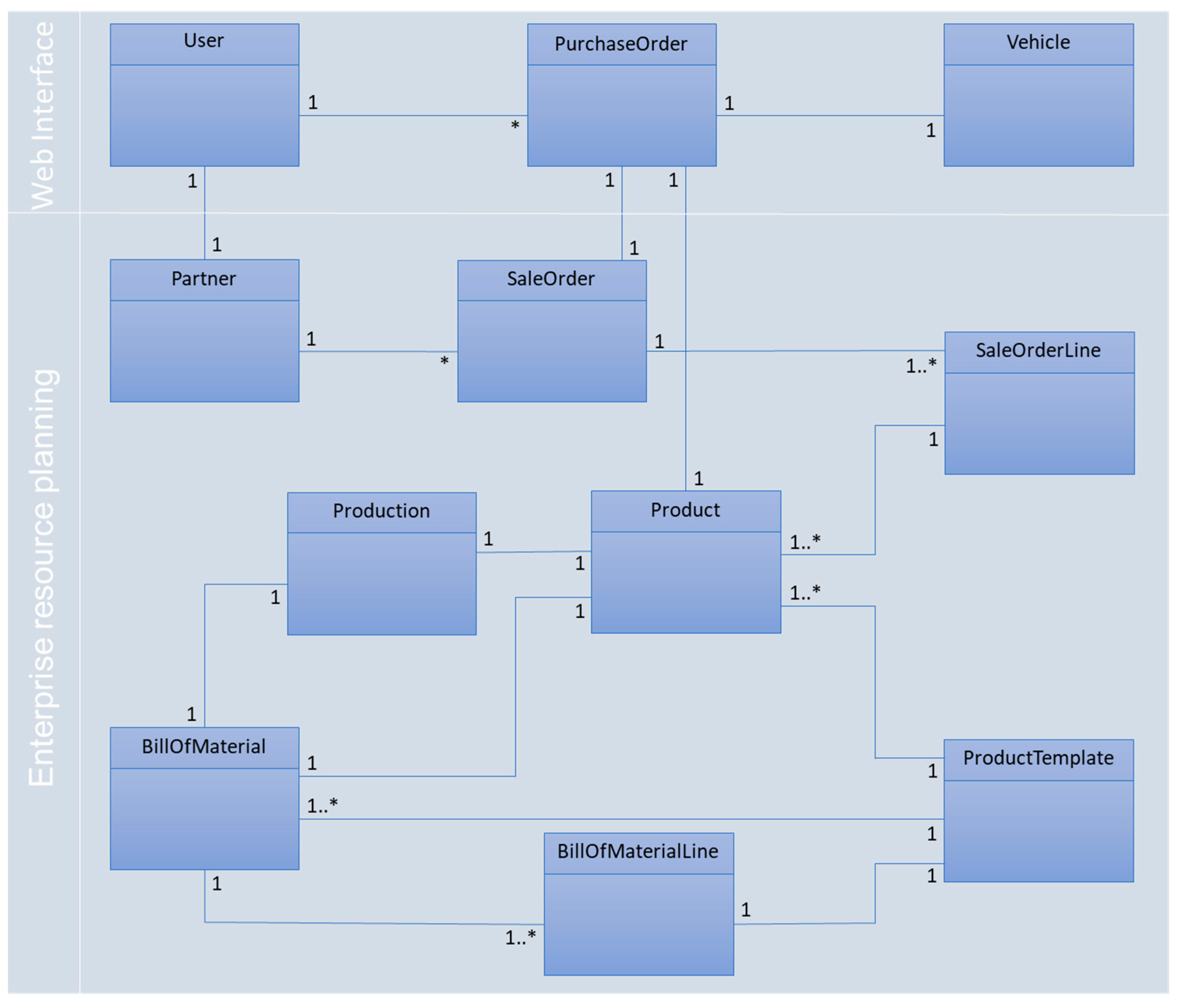
Figure 15 shows the class diagram of ERP and web applications, and the relations between them. The web application data model includes users of the systems and purchase orders they can make. The ERP data model shows the relations between sale orders, products, and production orders and how information moves from the initial user pre-order to the production of the product.
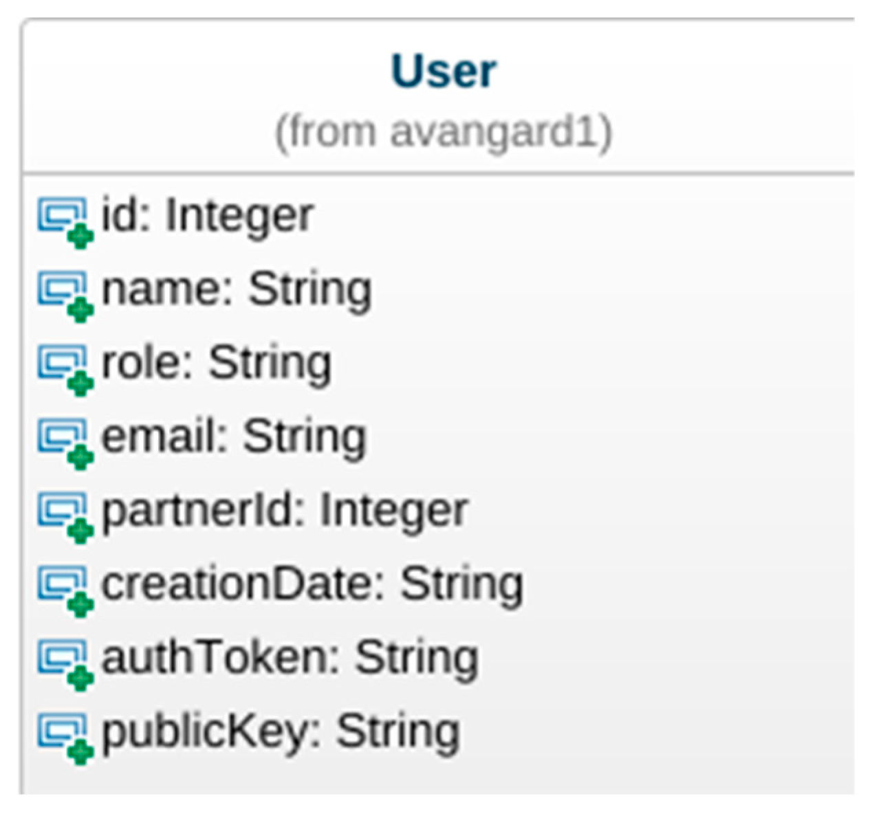
The User class (
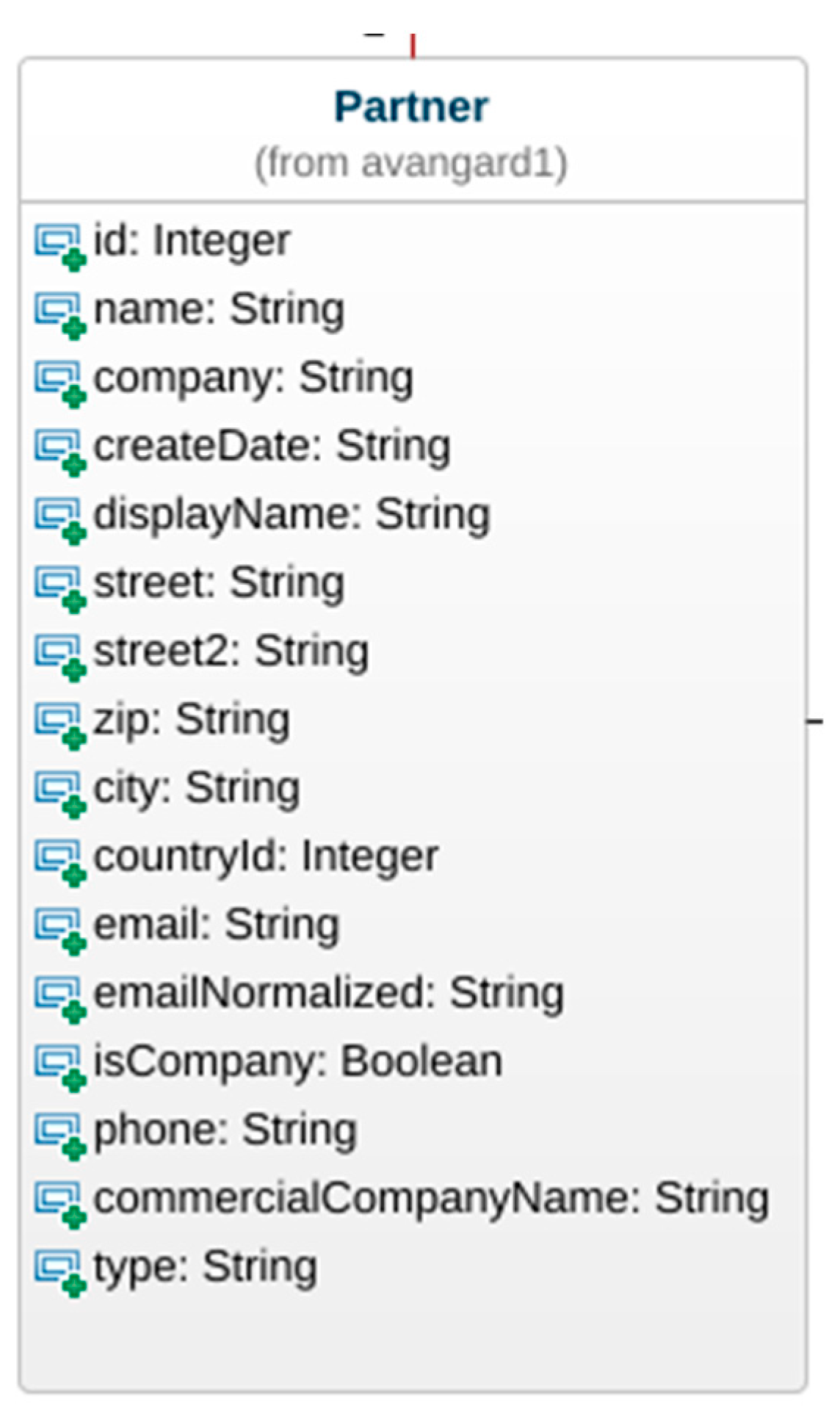
Figure 16) represents users in the web application. The Partner class (Figure 17) is related to the User class in the ERP system with a relation of one-to-one. To facilitate our integration with the blockchain (for traceability and trustability), the User class contains information about blockchain authToken and publicKey. The Partner class (Figure 17) is mostly used to identify the customers.
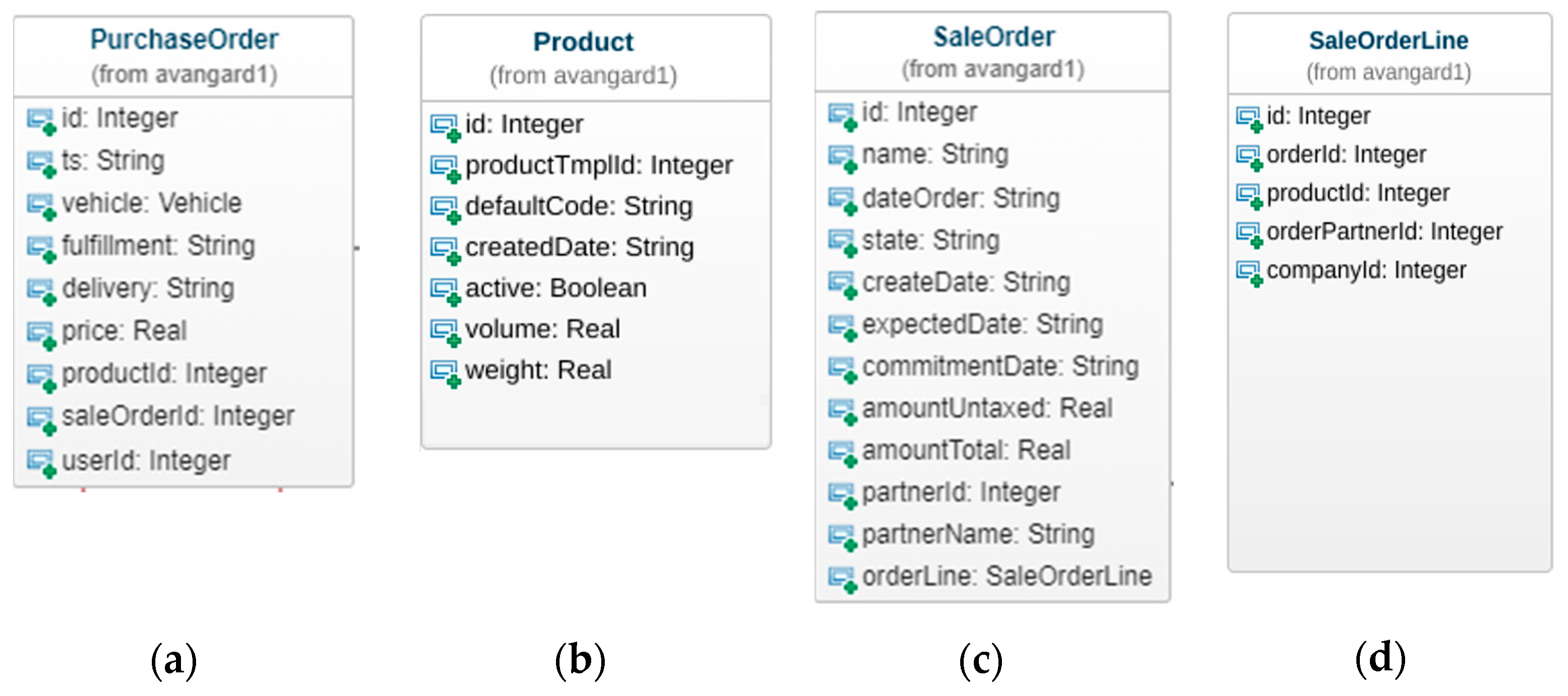
Users can create PurchaseOrders (Figure 18a), which are related to the Product class (Figure 18b) and ERP SaleOrder class (Figure 18c). PurchaseOrder contains necessary information about the sale to the cloud. The Product class contains the selected configuration of the product to be produced. SaleOrder is the class that contains the ERP sale information and has relation to the Partner class, which is the customer of the sale. Each customer can have multiple SaleOrders. Products ordered are contained in SaleOrderLine (Figure 18d) class, and SaleOrder can have multiple SaleOrderLines.
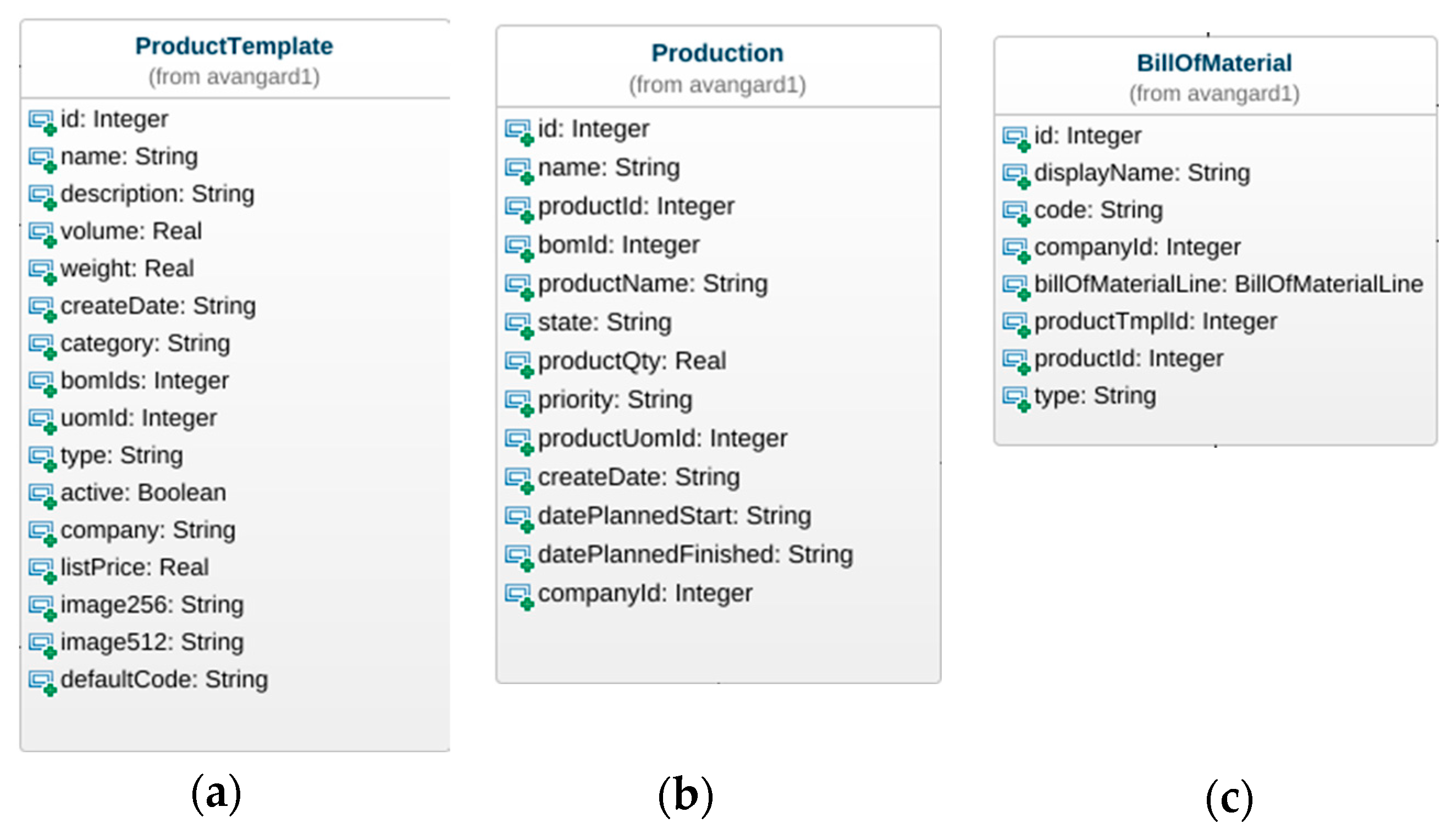
The Product class is related to the ProductTemplate (Figure 19a) and Production (Figure 19b) classes. ProductTemplate is the functional description of a kind of product, it includes the bill of materials (BoM) identification, category, and company, among other details.
For instance, ERP might have a basic template for the Basic product (on ProductTemplate). The Product class describes it more in-depth, with other details, for example, the color of the product. The Production class describes the manufacturing details of the ordered product and sub-product/parts. Production has a relation with the BillOfMaterial class (Figure 19c) which contains the list of parts needed to manufacture the product. BillOfMaterial can contain multiple BillOfMaterialLines that represent the parts needed to manufacture the final product to be delivered to the customer.

3.3.3. Manufacturing Execution Systems

MESs are tools designed to help on the shop floor and to follow the processes from the raw material until the finished product (or sub-product). These tools enable the decision makers to act in real time to improve processes. MESs are nowadays supported by IIoT where all kinds of sensors (and actuators) can be connected and interacted with from high- to low-level systems. In this way, there is a holistic approach from tools like ERP and LCA or PLCs and workers.
The use of MES can reduce time and costs on the shop floor if the information flows properly and if both the machines and processes from the factory are fully digitalized.
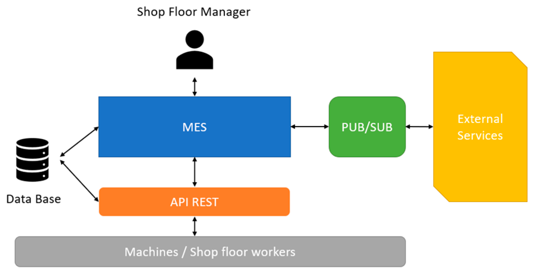
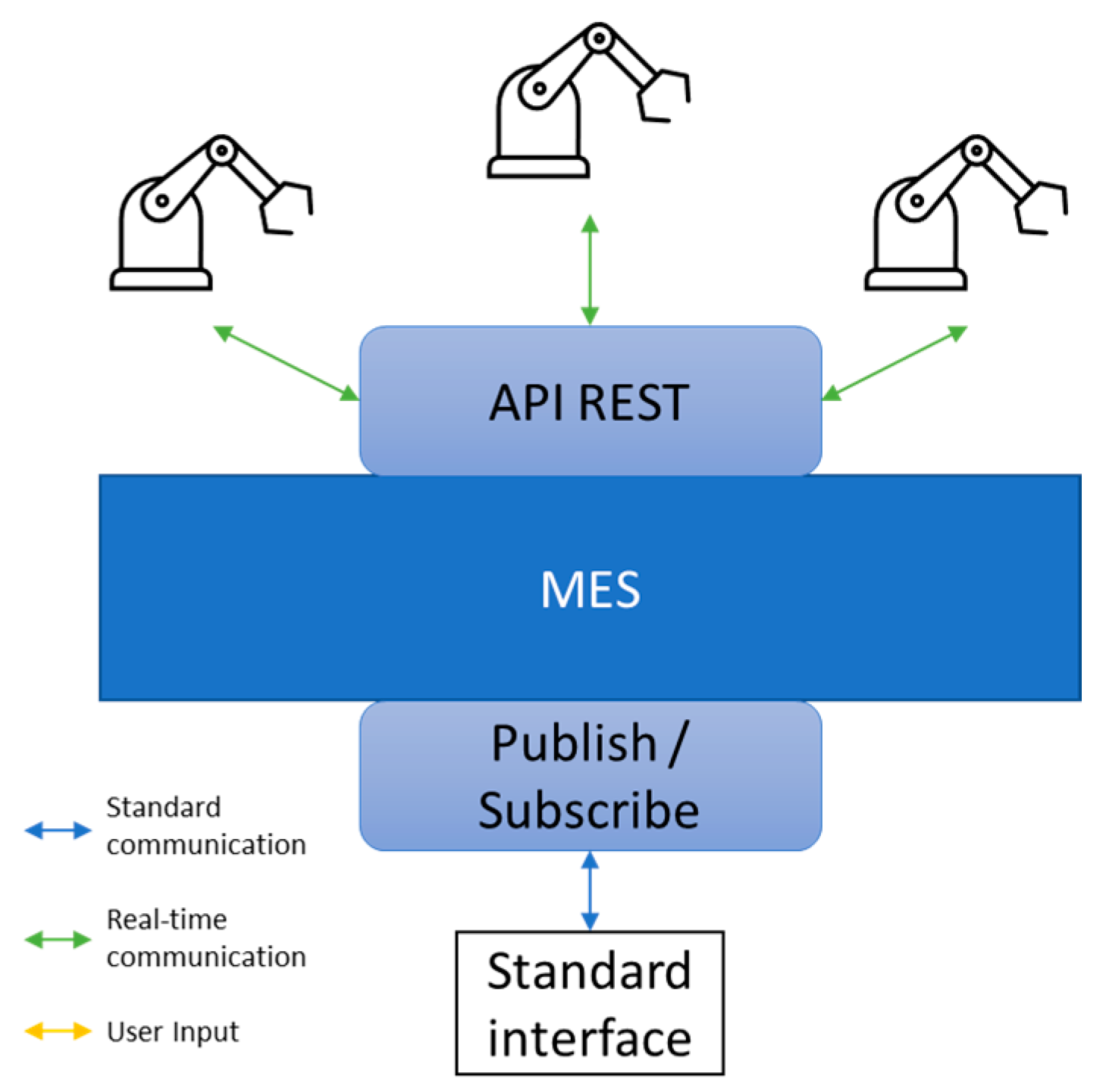
The MES architecture proposed is presented in Figure 20. MES is a type of software that can be used by a manager and has two interfaces: one with REST API, so machines and shop-floor workers can interact with the system (local), and another based on publish/subscribe methods, so external software can interact with the system (cloud-enabled). The local REST API can be seen as a gateway that was directly built in MES to simplify the operations on the shop floor. This MES software is also supported by a database that records all the actions relevant to the production environment.
With the publish/subscribe interface, MES can read or write on external software without changing their internal state and, if needed, can postpone this task giving priority to shop-floor control and management through the REST API (both communications are bi-directional as can be seen in Figure 21).
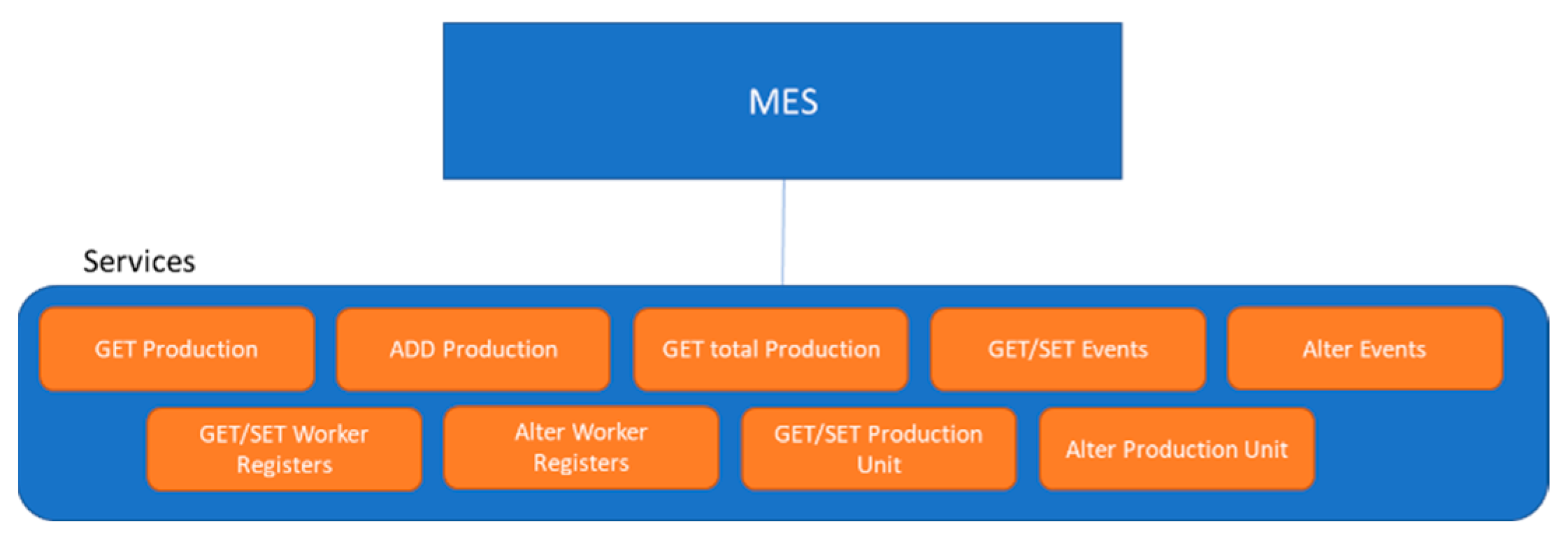
The REST API of MES enables the shop-floor machines to interact with the system but also enables the HMI to be connected, and a worker can add more information manually about the production processes. This API features the following services: Get Production, Add Production, Get total Production, Get Events, Set Events, Alter Event, Get Worker Registers, Set Worker Registers, Alter Worker Registers, Get Production Unit, Set Production Unit, and Alter Production Unit (as depicted in Figure 22). With this data, MES can create and show graphics and metrics available to managers to help with decision support.

3.3.4. Traceability/Trustability

In terms of traceability and trustability, the proposals stemming from the early investigation into the appropriate architecture to support a more generic framework of component interaction resulted in the use of a blockchain substrate. The ecosystem under evaluation required the integration of several key components including (a) an ERP to provide a customer interface and order placement, subsequently passed on to (b) the MES component to provide manufacturing control and (c) provide a programmatic allocation of hardware resources. The implementation was performed using Hyperledger Sawtooth (https://www.hyperledger.org/use/sawtooth (accessed on 7 September 2023)) since it was the one that after brief research seemed more appropriate. This technology has a loose coupling architecture, is more energy-efficient (than other blockchain implementations), has a Byzantine-fault tolerance, and implements parallel scheduling, the smart contracts can be developed in several programming languages like Python, C++, and JavaScript, among others, and it has two modes of operation, Permissioned and Permissionless.
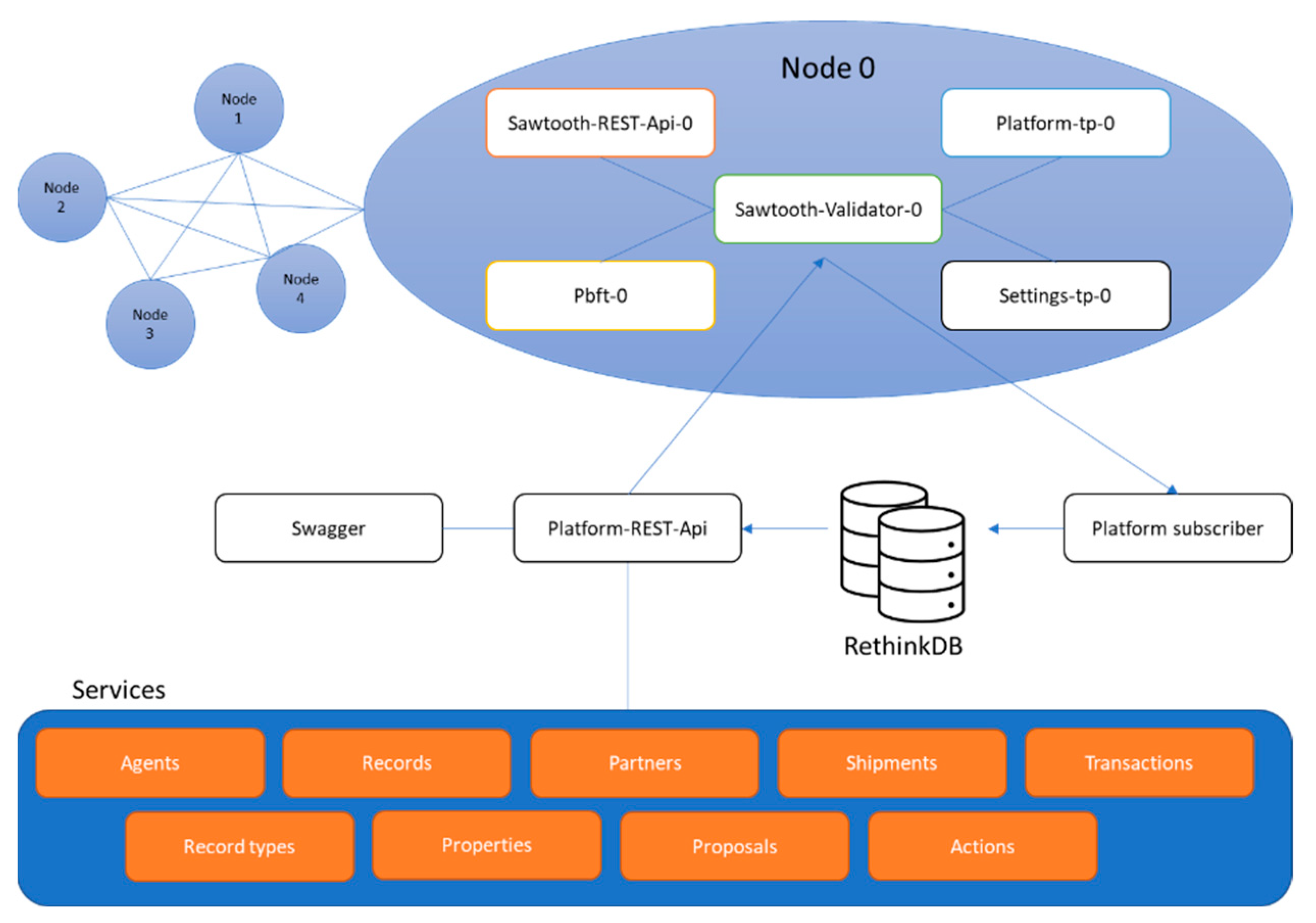
Since blockchain is a decentralized technology to be running in the cloud, four nodes were implemented inclusive of the required services to support the architecture integration requirements and support any future integrations, with real-world manufacturing environments. The following figure (Figure 23) outlines the network and exposes the services implemented.
A transaction family under the Hyperledger Sawtooth blockchain framework consists of application-specific business logic. A transaction family smart contract aimed to alter the data stored in addresses under the platform namespace. All data under a namespace prefix follow a consistent address and data encoding/serialization scheme that is determined by the transaction family, which in turn defines the namespace.
Hyperledger Sawtooth represents the state of all transaction families in a single instance of a Merkle–Radix tree on each Sawtooth validator. Data are stored in leaf nodes, and each node is accessed using an addressing scheme represented as a 70-hex character combination. The address format contains a 6-hex character prefix defining the namespace and 64-hex characters describing schemes for subdividing further and distinguishing entities (agents, records, etc.).

3.4. Use Cases

To validate the architecture, two use cases were developed. Since the main idea is to validate the architecture and its flexibility, some components were shared between both scenarios (such as the ERP), and others were completely different, suitable, and tailored for each one of the cases. For instance, one of the MES used follows the proposal from Section 3.3.3, and the other follows a more conventional approach trying to demonstrate that the architecture and this platform are compatible with both approaches. This section is not meant to describe to the reader how each component works but that each component is compliant with the architecture interfaces.
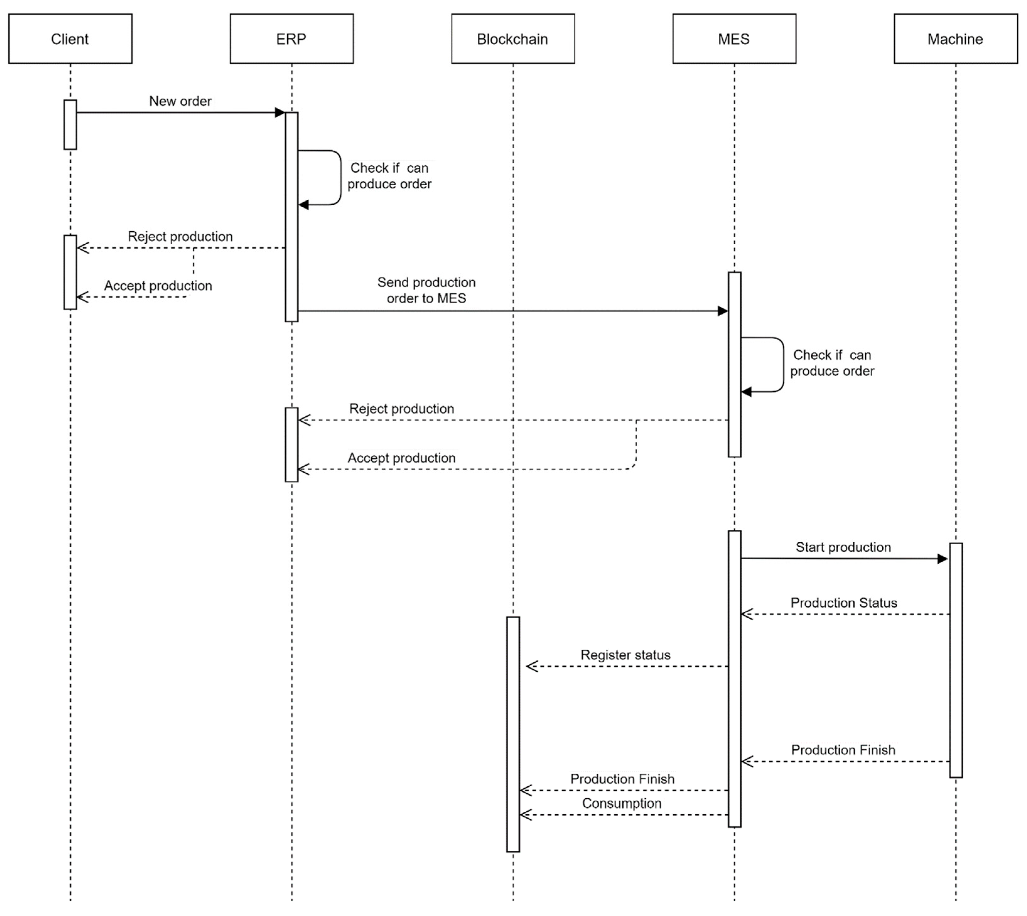
The ERP, located in the cloud, sends a production order to MES. In the MES, a manager from the factory will check if the order can be produced and accept or reject the order, accordingly. If the order is accepted, the MES sends the production order to the machine, within the factory, so it can start production. The machine gives the status of production to the MES as well as a confirmation when the production is finished. The transactions of this process are registered in the blockchain, and thus it can be reliably accessed, for example, by the ERP. This process is demonstrated in Figure 24.
In this scenario, energy consumption was one type of information agreed on by all stakeholders as vital data that should be exchanged in a trustable manner. With this information, the client can map and be informed of the impact that the production of his/her product has on the environment.

3.4.1. Application of 3D Printer for Additive Manufacturing

This use case is an end-to-end demonstration that can be applied to a network of micro-factories that can produce products with additive technologies such as 3D printers.
Using the same sequence diagram from 
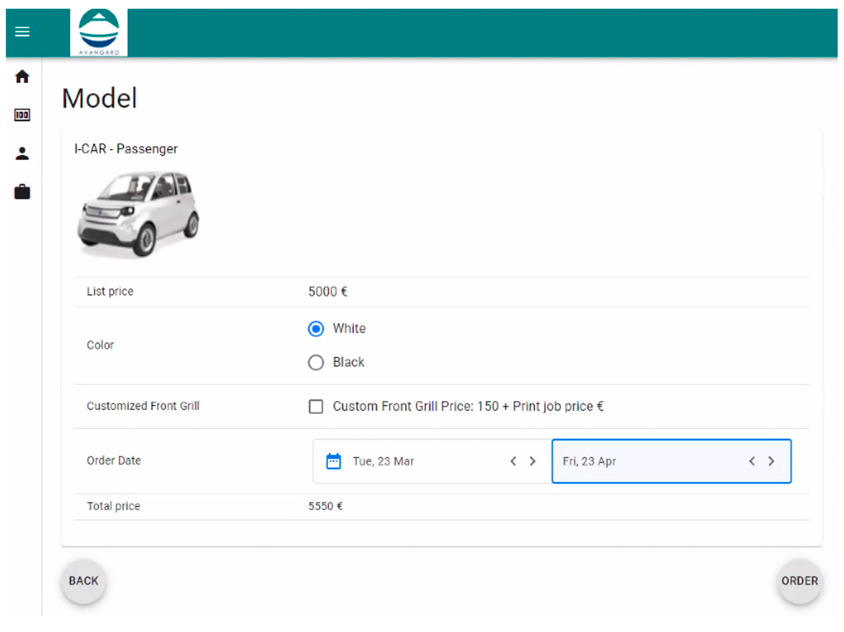
Figure 24, a new product is bought by the client, which places a new order (Figure 25 and Figure 26 depict the user interface to add an order).
Conventionally, the term “client” often evokes the notion of the end consumer; however, within the realm of micro-factories, the client paradigm expands to encompass entities such as Original Equipment Manufacturers (OEM). Figure 25 shows a listed price value. This listed price varies in conformance with several factors, such as the factory chosen proximity, production scheduling, premium freight, or electricity cost. The price has a fluctuation calculated by the ERP using these metrics that can be shared using the same mechanism of authenticity as the energy consumption that we focus on here. In 
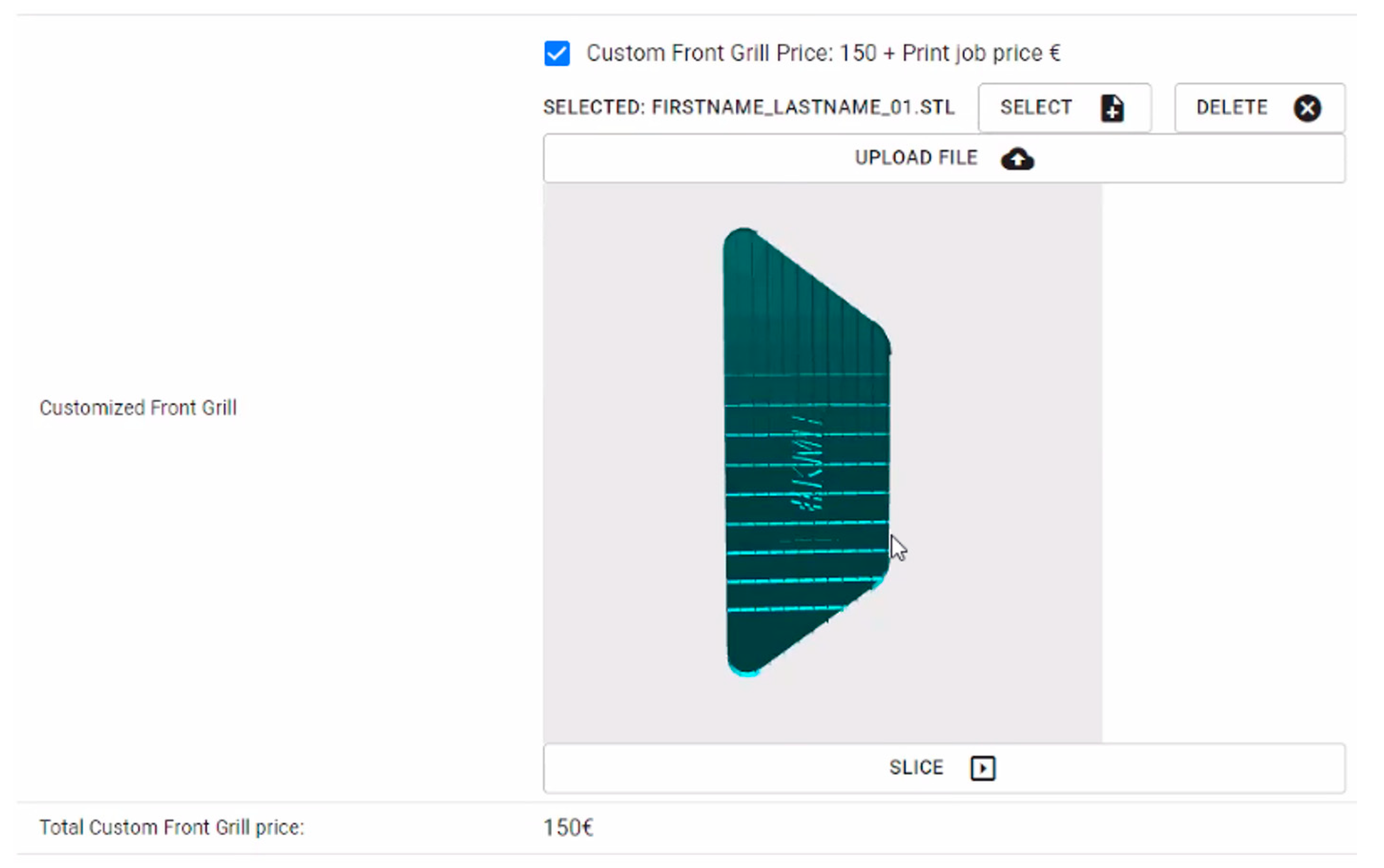
Figure 26, we illustrate the option to customize a component by sending a valid file (such as an *.stl file) through the ERP to the manufacturing site. This file, too, undergoes authentication and gains traceability through the blockchain component.
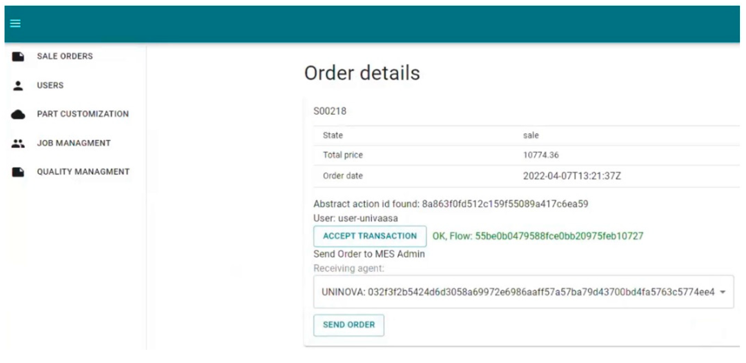
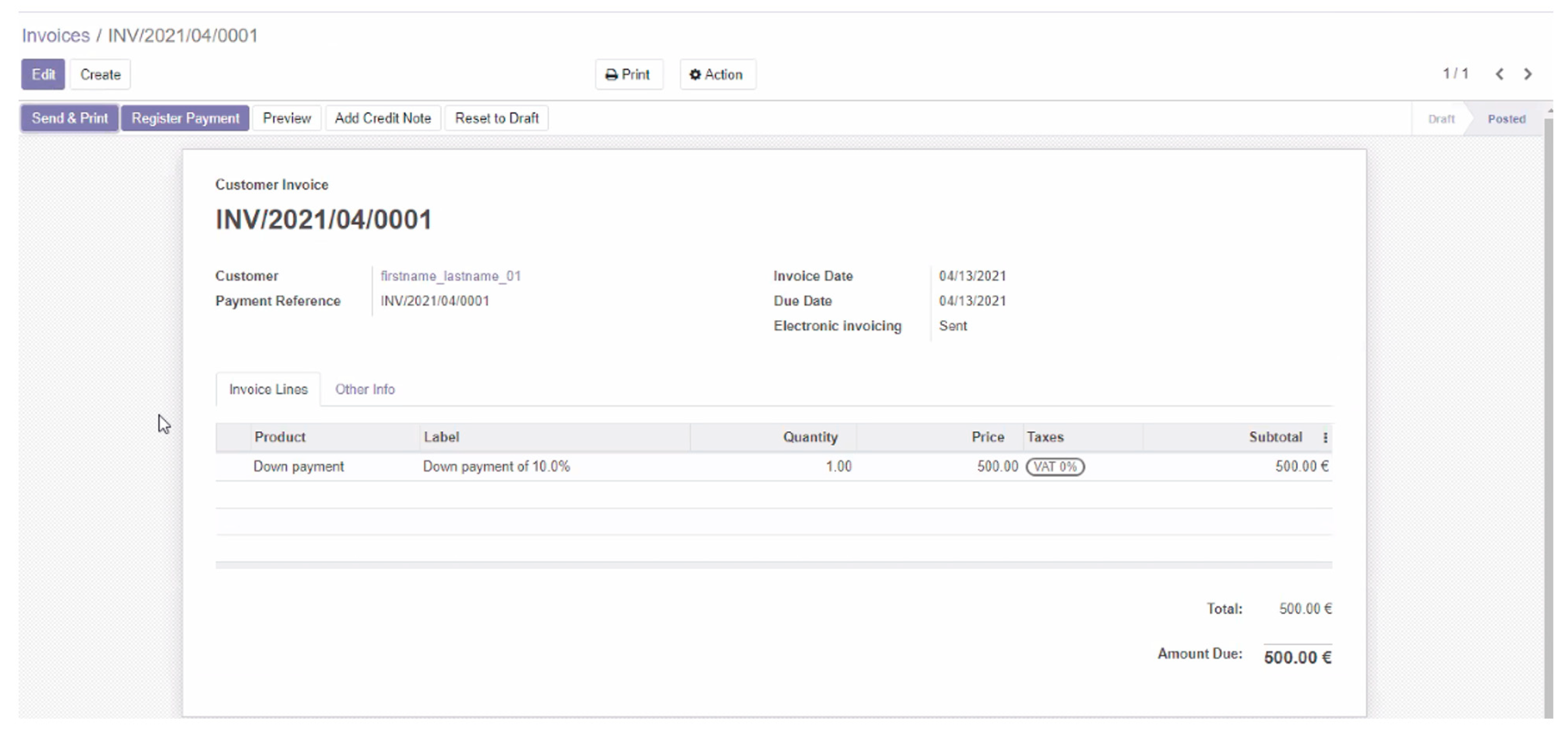
The order execution is validated by the ERP which sends an invoice to the client (Figure 27) and, through the cloud middleware, the information to the factory (
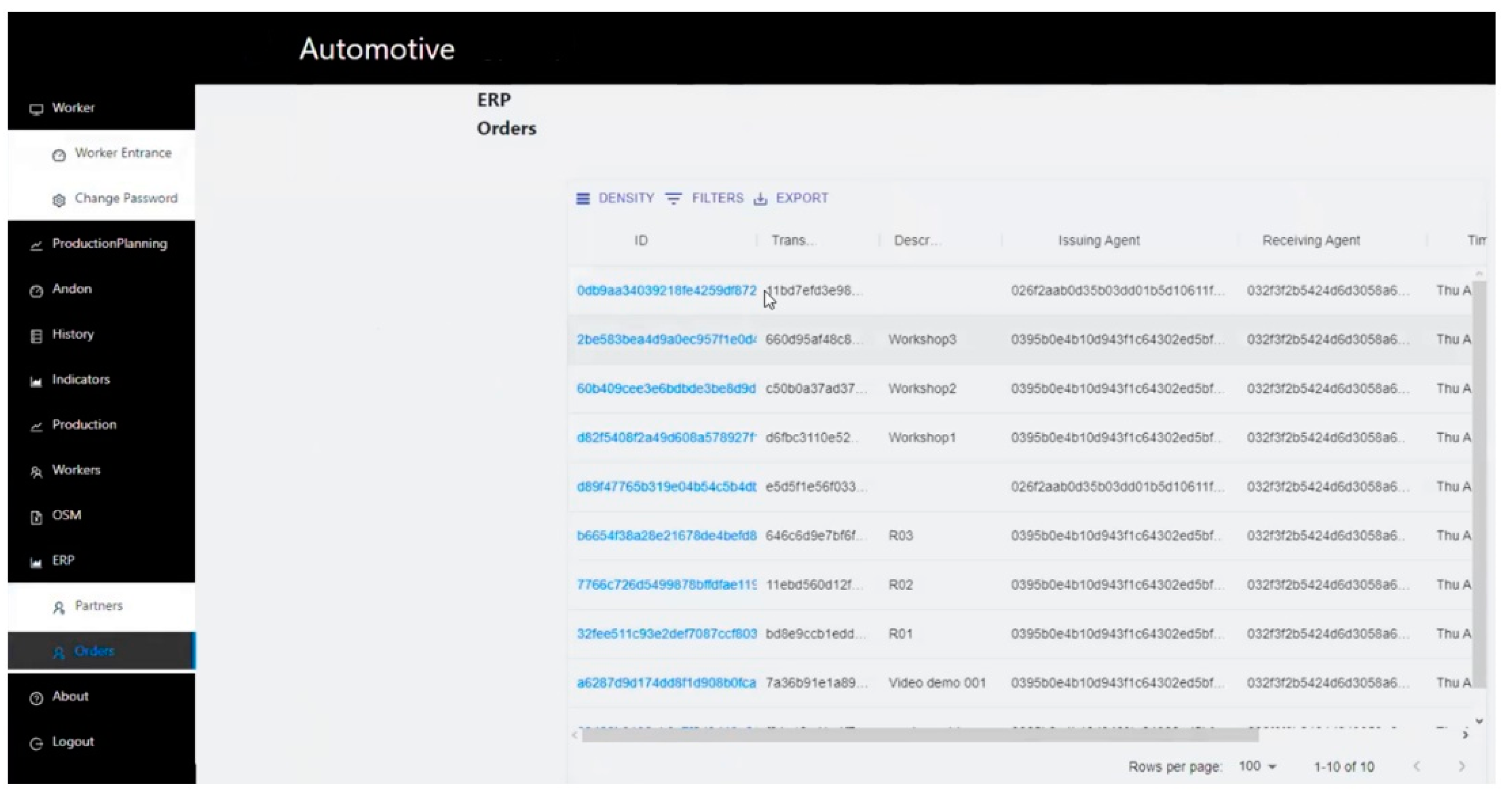
Figure 28).
As can be seen in Figure 28, the ERP interface displays solely the generated hashes. However, the information exchanged—readily available for auditing—comprises comprehensive details and specifications. In this instance, these details encompass factors such as filament type, color, density, and notably, the file housing the design of the part intended for printing.
With this information, the factory can accept or refuse the order (Figure 29). An acknowledgment is sent through the cloud middleware, and the manufacturing process (if accepted) starts (Figure 30).
In Figure 29, it is possible to see that the MES system is completely different from the ERP. They are instantiated in two different countries—ERP in Finland, MES in Portugal, and blockchain nodes in Greece—and rely on the cloud to exchange information. Time performance evaluations were not conducted during these tests, as they fell outside the scope of our objectives. The primary focus was on information exchange, a process consistently achieved within a delay of less than five seconds, and the authenticity of the data that could not be accessible from third parties.
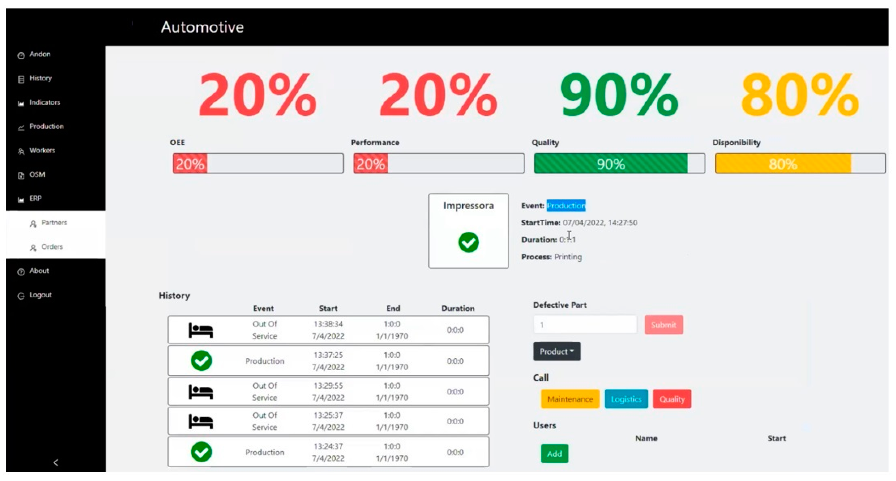
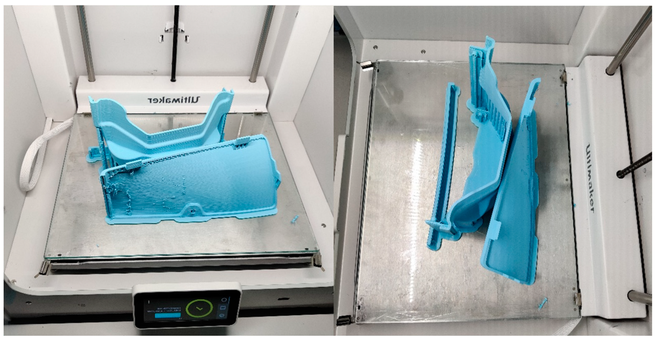
At the end of the production (Figure 31), the information about energy consumption is sent to the cloud middleware to be available to all tools that need it (Figure 32).
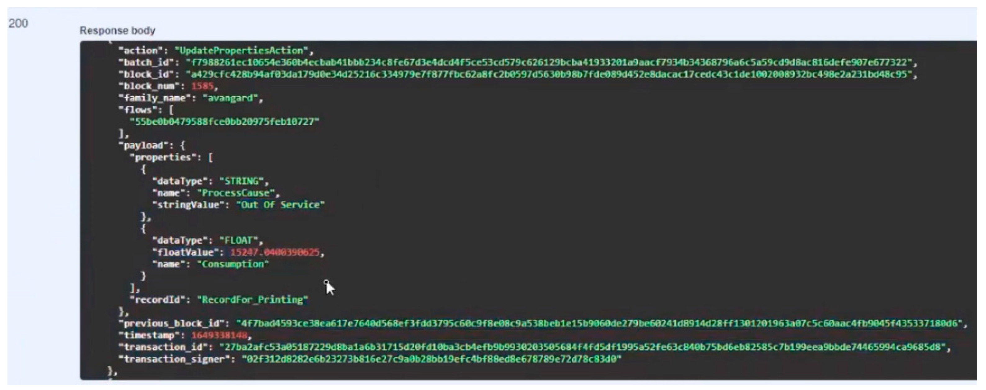
Figure 32 shows the output of the analyses that can be performed, by an authorized stakeholder, in which the progress and all the commitments done for the blockchain can be tracked. Stakeholders requiring access to energy consumption data, such as the ERP for conducting price analyses in this scenario, must be authorized at the blockchain level. The MES system internally stores these data within its own database; however, upon committing to the blockchain, it cannot read it from there due to a lack of reading authorization. An authorized entity has access to the information such as the one in Figure 32 where the “Consumption” can be seen, and the “flow” can be crosschecked in Figure 28. Looking at this use case, we can say that it was possible to use the architecture and the implemented platform in a heterogeneous environment since we demonstrated the use of several actors with different capabilities to achieve a common goal. This is an example of the use of cloud computing in the middleware, where horizontal integration, ERP, MES, and the blockchain are all different stakeholders, and the use of IoT in the sensors that measure the power consumption. This use case could be expanded using tools that make big data analyses or that contribute actively to developing other additive manufacturing techniques.

3.4.2. Welding Stations for the Automotive Industry

Just like the previous use case, in this scenario, the idea is to demonstrate an end-to-end interaction between all the actors, using the same architecture but highlighting the flexibility to have more stakeholders. For simplicity, we will maintain the ERP software (demonstrated by Figure 25, Figure 26, Figure 27 and 
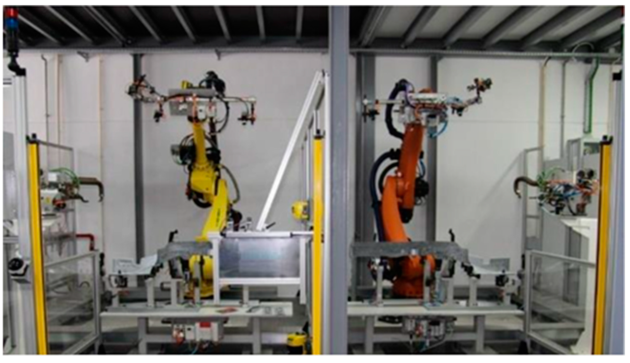
Figure 28), which will send the information to another partner to produce a different part. This use-case manufacturer is represented by two different industrial robotic cells, designed to perform spot welding processes (the two robotic cells can be seen on Figure 33). This scenario is implemented in an R&D facility and respects all current industry standards, in terms of safety, hardware, and ISOs; however, they are not included in any active production system or value chain. This means that these cells can provide industrial representative cells, without the major drawbacks of using cells integrated with active production systems.
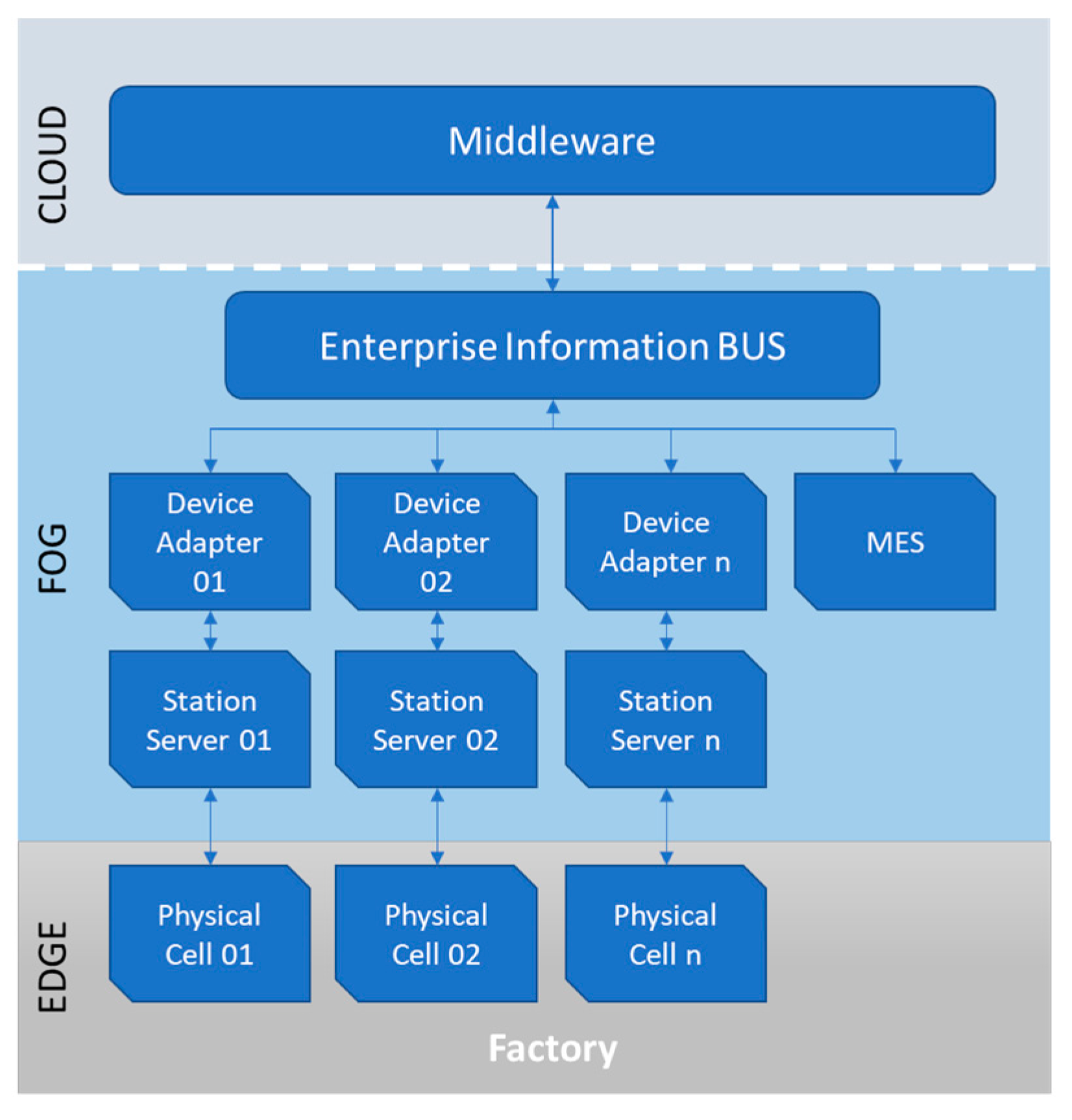
This use case uses a more traditional approach in which the machines and MES are connected to an “Enterprise Information BUS”. The topology is depicted in Figure 34 and allows one, with few modifications, to use any cloud system on top of it.
This system uses OPC UA as a medium of communication between the components, since it is the most widely accepted communication protocol in most industries, especially when considering the realities of the automotive sector and all the safety and internal policies of the different constructors.
The “Station Server” is responsible for providing communication middleware between hardware devices and the system in a bi-directional way. The “Device Adapter” is responsible for collecting the raw sensor data provided in the station server and processing it into relevant KPIs for the production process being performed and deconstructs complex orders to be produced by the unit. The “Enterprise Information Bus” is mainly responsible for creating bi-directional communications between components and providing features, such as the following: (i) allowing connection to potential cloud services, for which it provides an easy-to-use and integrated exporter that can be adapted to the most commonly used communication mediums seen in cloud services such as Kafka Apache and REST Servers; (ii) collecting production orders from one or multiple ERPs, in order to create instances of products that need to be produced; and (iii) managing the production and distribution of products according to the stations available in the network.
In this use case, MES has the task of assigning products (to be produced) to the available stations. To do so, data from various factors need to be validated such as production deadlines, sustainability, product quality requirements, and station usage, among many others. It is important to mention that the MES can access and use information from other components in the network and external cloud systems, like the orders from the ERP allowing for a more data-driven decision production optimization in the MES process.
This use case highlights the flexibility of the architecture and platform since the only requirement was the inclusion of the publish/subscribe mechanism and the agreed information to exchange, namely the spots and materials to weld as inputs and the energy consumption as an output. The architecture and implemented platform are agnostic to the actors that connect to it. The I4.0 paradigms represented here are the use of cloud infrastructure, horizontal integration, and IoT. In this scenario, we could also easily connect tools that enable augmented reality on the shop floor (and enhance the vertical integration inside the company) and simulation tools that could enhance the performance of the welding robots.

4. Discussion

In the context of I4.0, new and exciting ecosystems are being created, with a complexity never seen before. Analyzing Figure 6, it is noticeable that new software architectures are needed. Our approach, with a focus on the phenomenon of cloud computing, presents a software architecture that embraces the three main pillars of I4.0 [7]: vertical integration on the shop floors, horizontal integration between several stakeholders, and end-to-end engineering. It is implementable even with legacy controllers as depicted in Section 3.4.2.
During the development of this work, and aligned with the I4.0 concepts, we focused on the flexibility of communication between the several stakeholders (enhancing the horizontal integration) and the ability for traceability and trustability of produced parts (enhancing the end-to-end engineering concept). The architecture is very flexible since it was designed to have standard data models, enabling the use of new machines or retrofitting old ones and connecting them to other high-level systems such as MES or ERP (enhancing vertical integration). During the lifetime of a product, one or more actors can be connected or disconnected providing (or removing) valuable features. Although we recognize that this still has very low technical readiness, the use cases that we show in this document are provided by a synergy of different companies and academic institutions that represent several different stakeholders, distributed across several countries around Europe (namely Finland, Greece, and Portugal).
MES systems have been extensively tested and even more than one constructed for the two use cases. In the case of ERP, several studies have been conducted, and we felt that the open-source available platform Odoo (https://www.odoo.com/ (accessed on 7 September 2023)) was suitable for the task. On the topic of trustability and traceability, the choice of blockchain was made because it is an emergent technology that we felt would be highly adopted by industrial stack holders. Regarding the blockchain mechanism, extended exploratory work was done, and Hyperledger Sawtooth was chosen. On this platform, a lot of work was done to be able to create the correct permissions and contracts to fulfill the demonstration of the architecture proposed. Other tools could be developed to work at the cloud level, for instance, an LCA tool, but we felt that to demonstrate the capability of adaptation and flexibility of the architecture, these kinds of tools were not needed. Also, a second tool of trustability could be developed based on the paradigm of private/public key and third parties’ certificates, but again, the complexity and added value did not seem to add any additional value to the present work.
The presented architecture (Figure 10) was fully validated with the set of tools that we present in this work. It is scalable and stable due to being based on publish/subscribe mechanisms. Although our implementation has not been tested in a high-demand environment, with a lot of publishing nodes, from our experience, the Kafka software can handle high availability and high throughput of messages. Regarding the trustability of the data, our implementation was based on Hyperledger Sawtooth with a consensus mechanism and showed no concerns, although few nodes were deployed. No tests regarding the speed of communications or communication losses were performed since our implementation was carried out mainly to validate the architecture and not the performance. Our verdict is that the architecture is valid but will always depend on the nature of the stakeholders. From our research, no other architecture demonstrates this flexibility nor does an implementation seem to take into account the traceability or trustability of data or other tools to support end-to-end engineering. So, we can state that our architecture touches the three main pillars of I4.0 and is directly proved to be supported by three of the eight enablers of I4.0.
Although an effort was made to validate it in a fully industrial environment, only part of the work was mature enough to be implemented on a running plant. Nevertheless, the architecture was planned to be fully implemented in the context of micro-factories and, in particular, in the construction of electrical vehicles. All mechanisms’ developed work and a buying experience, from end to end, were possible to achieve. Also, the implementation of LCA tools can be achieved and integrated smoothly into the use cases presented, and they can be an added value to the electric vehicle business. We highlight the need for a stronger and more focused set of tools, namely other implementations for the publish/subscribe modules, traceability, and trustability.

5. Conclusions

In this work, an architecture is presented to be used in the context of European micro-factories. It was designed keeping in mind the need to be ready for different and complex manufacturing environments, with a deep focus on using cloud-based technologies. The architecture works on three levels, Edge, FOG, and cloud, with a middleware system on the cloud that stores all relevant data and interfaces with the different applications from different stakeholders. A second middleware system, in the FOG layer, dedicated to the factories, stores the different services that are available in a Yellow Page structure.
To demonstrate the viability of this concept, two use cases are presented, a 3D printer application for additive manufacturing and welding stations for the automotive industry. The architecture can be applied, and it is valid for both scenarios. These scenarios differed in the last steps, the effective production of the part, and enhancing the modularity that the architecture enables. The concern about the trustability of data exchange can be dissipated using this architecture, allied with a module based on blockchain, as we did. In the scenarios described, the consumption of the manufacturing process was the information item that we wanted to share between actors. The consumption data cannot be changed by a third party after being committed to the blockchain, as expected. Regarding traceability, the blockchain tool enabled the right actors to trace the production from its beginning (order placed) to the production end (that for simplicity was our delivery), but not even the system administrator can access these data without the correct permissions.
As a future work, we would like to pen-test the cloud middleware to understand if the off-shelf mechanisms from the publish/subscribe services are enough to warranty the data delivery from and to the several stack holders. Also important at the cloud middleware level, we would like to test the resilience of the publish/subscribe methods against failures, cascade failures, overload, and other interesting concepts that were not in the scope of this work. New tools can also be developed and integrated to connect to the cloud middleware that can easily deploy simulation features, big data analyses, autonomous robot tracking, and plan optimization or support augmented reality to give different stakeholders of the process a better and interactive view of the critical processes during the manufacturing of goods.

Author Contributions

Conceptualization, A.D.R., A.P., R.T., N.T., P.S., P.P., and J.B.; Methodology, F.M.-O. and D.A.; Software, F.M.-O., N.F., J.S., and C.A.; Validation, A.D.R., A.P., R.T., N.T., and J.B.; Formal analysis, F.M.-O. and A.D.R.; Investigation, A.D.R. and P.P.; Writing—original draft preparation, A.D.R.; Writing—review and editing, F.M.-O.; Supervision, J.B. All authors have read and agreed to the published version of the manuscript.

Funding

This research has received funding from the European Union’s Horizon 2020 research and innovation programme under grant agreement number 869986.Applsci 13 10223 i001

Institutional Review Board Statement

Not applicable.

Informed Consent Statement

Not applicable.

Data Availability Statement

Data sharing not applicable.

Acknowledgments

The authors would like to extend their sincere gratitude to Introsys—Global Control System Designers for their valuable assistance and generous provision of resources that significantly contributed to the completion of this research.

Conflicts of Interest

The authors declare no conflict of interest.

References

  1. Gilchrist, A. Industry 4.0. Opportunities and Challenges of the New Industrial Revolution for Developing Countries and Economies in Transition. In 2030 Agenda and the Sustainable Development Goals (SDGs); Apress: Berkeley, CA, USA, 2016. [Google Scholar] [CrossRef]
  2. Bnouhanna, N.; Neugschwandtner, G. Cross-Factory Information Exchange for Cloud-Based Monitoring of Collaborative Manufacturing Networks. In Proceedings of the 2019 24th IEEE International Conference on Emerging Technologies and Factory Automation (ETFA), Zaragoza, Spain, 10–13 September 2019; pp. 1203–1206. [Google Scholar] [CrossRef]
  3. Kannisto, P.; Hästbacka, D.; Marttinen, A. Information Exchange Architecture for Collaborative Industrial Ecosystem. Inf. Syst. Front. 2018, 22, 655–670. [Google Scholar] [CrossRef]
  4. Vogt, A.; Müller, R.K.; Kampa, T.; Stark, R.; Großmann, D. Concept and Architecture for Information Exchange between Digital Twins of the Product (CPS) and the Production System (CPPS). Procedia CIRP 2021, 104, 1292–1297. [Google Scholar] [CrossRef]
  5. Yoon, S.; Um, J.; Suh, S.-H.; Stroud, I.; Yoon, J.-S. Smart Factory Information Service Bus (SIBUS) for manufacturing application: Requirement, architecture and implementation. J. Intell. Manuf. 2019, 30, 363–382. [Google Scholar] [CrossRef]
  6. Frank, A.G.; Dalenogare, L.S.; Ayala, N.F. Industry 4.0 technologies: Implementation patterns in manufacturing companies. Int. J. Prod. Econ. 2019, 210, 15–26. [Google Scholar] [CrossRef]
  7. Stock, T.; Seliger, G. Opportunities of Sustainable Manufacturing in Industry 4.0. Procedia CIRP 2016, 40, 536–541. [Google Scholar] [CrossRef]
  8. Brettel, M.; Friederichsen, N.; Keller, M.; Rosenberg, M. How Virtualization, Decentralization and Network Building Change the Manufacturing Landscape: An Industry 4.0 Perspective. Int. J. Mech. Ind. Aerosp. Sci. 2014, 8, 37–44. [Google Scholar] [CrossRef]
  9. Mabkhot, M.M.; Ferreira, P.; Maffei, A.; Podržaj, P.; Mądziel, M.; Antonelli, D.; Lanzetta, M.; Barata, J.; Boffa, E.; Finžgar, M.; et al. Mapping Industry 4.0 Enabling Technologies into United Nations Sustainability Development Goals. Sustainability 2021, 13, 2560. [Google Scholar] [CrossRef]
  10. Ghimire, S. Self-Evolutionary Cyber Physical Systems: Leap towards Smart CPS; Faculdade de Ciências e Tecnologia da Universidade Nova de Lisboa: Caparica, Portugal, 2016; p. 221. [Google Scholar]
  11. Liu, C.; Jiang, P. A Cyber-physical System Architecture in Shop Floor for Intelligent Manufacturing. Procedia CIRP 2016, 56, 372–377. [Google Scholar] [CrossRef]
  12. Kagermann, H.; Wahlster, W.; Helbig, J. Recommendations for Implementing the Strategic Initiative INDUSTRIE 4.0. Final Report of Industrie 4.0 Working Group; National Academy of Science and Engineering: Munich, Germany, 2013. [Google Scholar] [CrossRef]
  13. Wang, L.; Wang, X.V. Cloud-Based Cyber-Physical Systems in Manufacturing, 1st ed.; Springer International Publishing: Cham, Switzerland, 2018. [Google Scholar] [CrossRef]
  14. Zhang, Q.; Cheng, L.; Boutaba, R. Cloud computing: State-of-the-art and research challenges. J. Internet Serv. Appl. 2010, 1, 7–18. [Google Scholar] [CrossRef]
  15. Rountree, D.; Castrillo, I. The Basics of Cloud Computing. In The Basics of Cloud Computing; Elsevier Inc.: Amsterdam, The Netherlands, 2014. [Google Scholar] [CrossRef]
  16. Winkler, V. Securing the Cloud: Cloud Computer Security Techniques and Tactics, 1st ed.; Elsevier: Amsterdam, The Netherlands, 2011; ISBN 978-1-59749-592-9. [Google Scholar]
  17. Wu, D.; Greer, M.J.; Rosen, D.W.; Schaefer, D. Cloud manufacturing: Strategic vision and state-of-the-art. J. Manuf. Syst. 2013, 32, 564–579. [Google Scholar] [CrossRef]
  18. Chaâri, R.; Ellouze, F.; Koubâa, A.; Qureshi, B.; Pereira, N.; Youssef, H.; Tovar, E. Cyber-physical systems clouds: A survey. Comput. Netw. 2016, 108, 260–278. [Google Scholar] [CrossRef]
  19. Lai, D.; Zhang, L.; Xu, B.; Liu, C. Task scheduling for cloud based cyber-physical systems. In Proceedings of the 2018 IEEE SmartWorld, Ubiquitous Intelligence and Computing, Advanced and Trusted Computing, Scalable Computing and Communications, Cloud and Big Data Computing, Internet of People and Smart City Innovations, SmartWorld/UIC/ATC/ScalCom/CBDCo, Guangzhou, China, 8–12 October 2018; pp. 1455–1460. [Google Scholar] [CrossRef]
  20. Wang, X.V.; Wang, L.; Mohammed, A.; Givehchi, M. Ubiquitous manufacturing system based on Cloud: A robotics application. Robot Comput. Integr. Manuf. 2017, 45, 116–125. [Google Scholar] [CrossRef]
  21. Gherardi, L.; Hunziker, D.; Mohanarajah, G. A software product line approach for configuring cloud robotics applications. In Proceedings of the IEEE International Conference on Cloud Computing, CLOUD, Anchorage, AK, USA, 27 June 2014–2 July 2014; pp. 745–752. [Google Scholar] [CrossRef]
  22. Shu, Z.; Wan, J.; Zhang, D.; Li, D. Cloud-Integrated Cyber-Physical Systems for Complex Industrial Applications. Mob. Netw. Appl. 2016, 21, 865–878. [Google Scholar] [CrossRef]
  23. Keung, K.L.; Lee, C.K.M.; Ji, P.; Ng, K.K.H. Cloud-Based Cyber-Physical Robotic Mobile Fulfillment Systems: A Case Study of Collision Avoidance. IEEE Access 2020, 8, 89318–89336. [Google Scholar] [CrossRef]
  24. Caldeira, R. openMOS. 2017. Available online: https://www.openmos.eu/ (accessed on 3 November 2022).
  25. Gepp, M. Horizon2020-PERFoRM. 2017. Available online: https://www.horizon2020-perform.eu/ (accessed on 3 November 2022).
  26. Dang, T.A.T.; Bosch-Mauchand, M.; Arora, N.; Prelle, C.; Daaboul, J. Electromagnetic modular Smart Surface architecture and control in a microfactory context. Comput. Ind. 2016, 81, 152–170. [Google Scholar] [CrossRef]
  27. Elango, M.; Subramanian, N.; Marian, R.; Goh, M. Distributed hybrid multiagent task allocation approach for dual-nozzle 3D printers in microfactories. Int. J. Prod. Res. 2016, 54, 7014–7026. [Google Scholar] [CrossRef]
  28. Gendreau, D.G.; Akotondrabe, M.R.; Utz, P.L. Towards reconfigurable and modular microfactory based on the TRING-module stick-slip microrobot. In Proceedings of the 8th International Workshop on Microfactories, Tampere, Finland, 18 June 2012; pp. 1–6. [Google Scholar]
  29. Papacharalampopoulos, A.; Tzimanis, K.; Stavropoulos, P. A decision support tool for dynamic LCA: The FDM paradigm. Procedia CIRP 2022, 112, 543–548. [Google Scholar] [CrossRef]
  30. European Commission. The European Green Deal; European Commission: Brussels, Belgium, 2019. [Google Scholar]
  31. Rüßmann, M.; Lorenz, M.; Gerbert, P.; Waldner, M.; Justus, J.; Engel, P.; Harnisch, M. Future of Productivity and Growth in Manufacturing; Boston Consulting: Boston, MA, USA, 2015. [Google Scholar] [CrossRef]
  32. Haddara, M.; Elragal, A. The Readiness of ERP Systems for the Factory of the Future. Procedia Comput. Sci. 2015, 64, 721–728. [Google Scholar] [CrossRef]
  33. Boykin, R.F. Enterprise resource planning software: A solution to the return material authorization problem. Comput. Ind. 2001, 45, 99–109. [Google Scholar] [CrossRef]
  34. Chen, I.J. Planning for ERP systems: Analysis and future trend. Bus. Process. Manag. J. 2001, 7, 374–386. [Google Scholar] [CrossRef]
  35. Yen, D.C.; Chou, D.C.; Chang, J. A synergic analysis for Web-based enterprise resources planning systems. Comput. Stand. Interfaces 2002, 24, 337–346. [Google Scholar] [CrossRef]
  36. Gardiner, S.C.; Hanna, J.B.; LaTour, M.S. ERP and the reengineering of industrial marketing processes: A prescriptive overview for the new-age marketing manager. Ind. Mark. Manag. 2002, 31, 357–365. [Google Scholar] [CrossRef]
  37. Markus, M.L.; Axline, S.; Petrie, D.; Tanis, C. Learning from adopters’ experiences with ERP: Problems encountered and success achieved. J. Inf. Technol. 2000, 15, 245–265. [Google Scholar] [CrossRef]
  38. ISO 14044:2006; Environmental Management—Life Cycle Assessment—Requirements and Guidelines. ISO: Geneva, Switzerland, 2006. Available online: https://www.iso.org/obp/ui/#iso:std:iso:14044:ed-1:v1:en (accessed on 16 November 2022).
  39. Akkermans, S.; Bachiller, R.; Matthys, N.; Joosen, W.; Hughes, D.; Vučinić, M. Towards efficient publish-subscribe middleware in the IoT with IPv6 multicast. In Proceedings of the 2016 IEEE International Conference on Communications (ICC), Kuala Lumpur, Malaysia, 22–27 May 2016; pp. 1–5. [Google Scholar] [CrossRef]
  40. Rocha, A.D.; Freitas, N.; Alemão, D.; Guedes, M.; Martins, R.; Barata, J. Event-Driven Interoperable Manufacturing Ecosystem for Energy Consumption Monitoring. Energies 2021, 14, 3620. [Google Scholar] [CrossRef]
  41. Pan, S.; Trentesaux, D.; McFarlane, D.; Montreuil, B.; Ballot, E.; Huang, G.Q. Digital interoperability in logistics and supply chain management: State-of-the-art and research avenues towards Physical Internet. Comput. Ind. 2021, 128, 103435. [Google Scholar] [CrossRef]
Figure 1. CPS architecture on shop floor, based on [11].
Applsci 13 10223 g001
Figure 2. CC architecture (based on [14]).
Applsci 13 10223 g002
Figure 3. Service levels of cloud services (adapted from [13]).
Applsci 13 10223 g003
Figure 4. CM architecture, based on [17].
Applsci 13 10223 g004
Figure 5. Comparison between conventional, web-based, and cloud-based robots (adapted from [13]).
Applsci 13 10223 g005
Figure 6. Example ecosystem with heterogeneous stakeholders, at different levels.
Applsci 13 10223 g006
Figure 7. Platform example that enumerates some of the potential stakeholders with a focus on middleware between local (EDGE or FOG) and cloud.
Applsci 13 10223 g007
Figure 8. Enablers from I4.0 which the platform is demonstrated to use.
Applsci 13 10223 g008
Figure 9. Interaction between execution system and other systems.
Applsci 13 10223 g009
Figure 10. Proposed Cloud-based Architecture.
Applsci 13 10223 g010
Figure 11. Detail on cloud middleware.
Applsci 13 10223 g011
Figure 12. A pattern of a message path through publish/subscribe middleware, based on [40].
Applsci 13 10223 g012
Figure 13. FOG middleware in detail.
Applsci 13 10223 g013
Figure 14. Detail on the connections to the cloud middleware by transport operators and suppliers.
Applsci 13 10223 g014
Figure 15. Representation of the class diagram of ERP. (1..* stands for one or more).
Applsci 13 10223 g015
Figure 16. User class.
Applsci 13 10223 g016
Figure 17. Partner class.
Applsci 13 10223 g017
Figure 18. (a) PurchaseOrder class; (b) Product class; (c) SaleOrder class; (d) SaleOrderLine.
Applsci 13 10223 g018
Figure 19. (a) ProductTemplate class; (b) Production class; (c) BillOfMaterial class.
Applsci 13 10223 g019
Figure 20. MES architecture.
Applsci 13 10223 g020
Figure 21. MES interfaces (no user input).
Applsci 13 10223 g021
Figure 22. REST API services.
Applsci 13 10223 g022
Figure 23. Hyperledger Sawtooth blockchain implementation.
Applsci 13 10223 g023
Figure 24. Sequence diagram from interactions for use cases.
Applsci 13 10223 g024
Figure 25. Order creation by the client.
Applsci 13 10223 g025
Figure 26. Customization of a 3D printable part.
Applsci 13 10223 g026
Figure 27. Invoice creation.
Applsci 13 10223 g027
Figure 28. ERP interface to send orders to partners.
Applsci 13 10223 g028
Figure 29. MES interface to receive or reject orders from partners.
Applsci 13 10223 g029
Figure 30. MES interface (printer with the event production).
Applsci 13 10223 g030
Figure 31. Production result.
Applsci 13 10223 g031
Figure 32. Blockchain interface with consumption data.
Applsci 13 10223 g032
Figure 33. R&D facilities with two different welding stations.
Applsci 13 10223 g033
Figure 34. Welding use-case architecture.
Applsci 13 10223 g034
Disclaimer/Publisher’s Note: The statements, opinions and data contained in all publications are solely those of the individual author(s) and contributor(s) and not of MDPI and/or the editor(s). MDPI and/or the editor(s) disclaim responsibility for any injury to people or property resulting from any ideas, methods, instructions or products referred to in the content.

