
Numerical Analysis Exterior RC Beam-Column Joints with CFRP Bars as Beam’s Tensional Reinforcement under Cyclic Reversal Deformations


Abstract
:1. Introduction
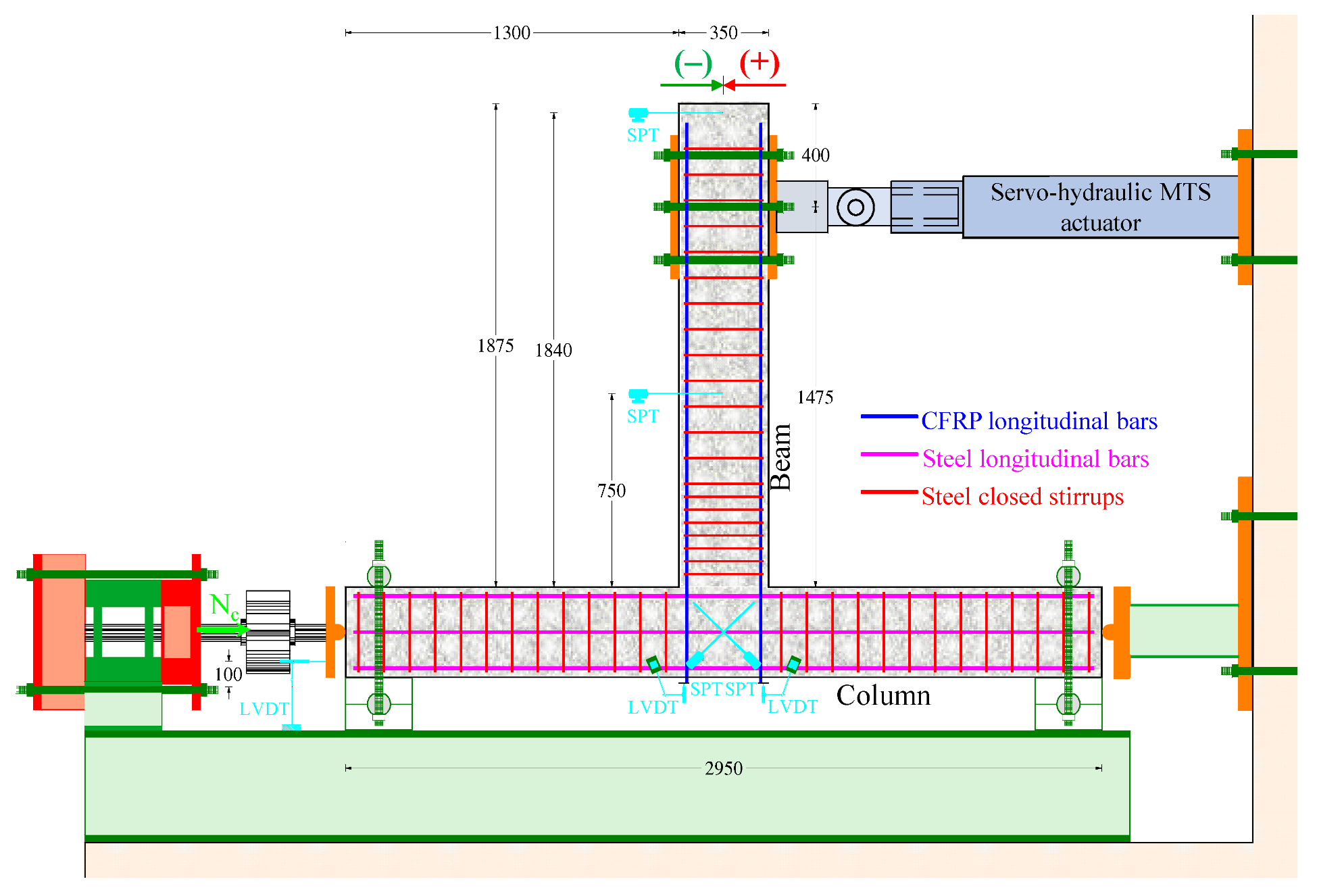
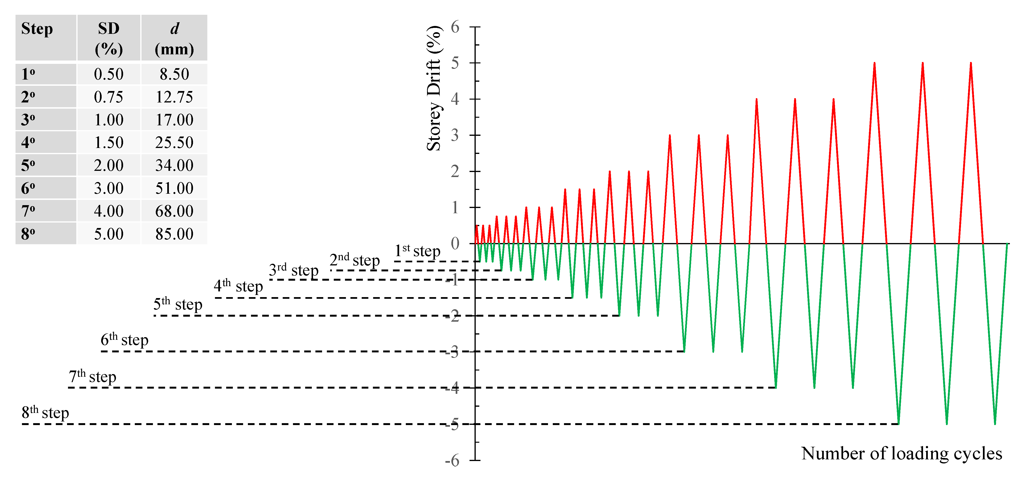
2. Experimental Test Program
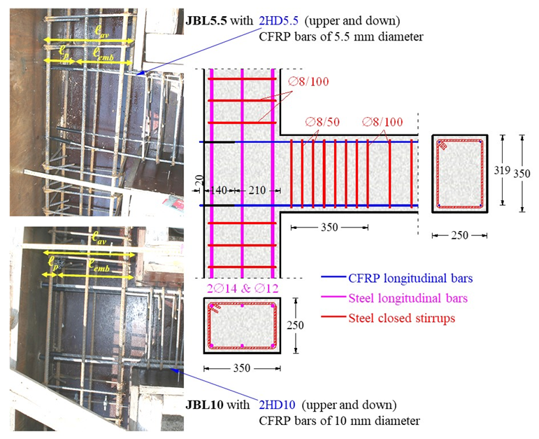
2.1. Geometry and Reinforcement Characteristics of the Specimens
2.2. Mechanical Properties of Materials
2.2.1. Concrete
2.2.2. Steel and CFRP Reinforcement
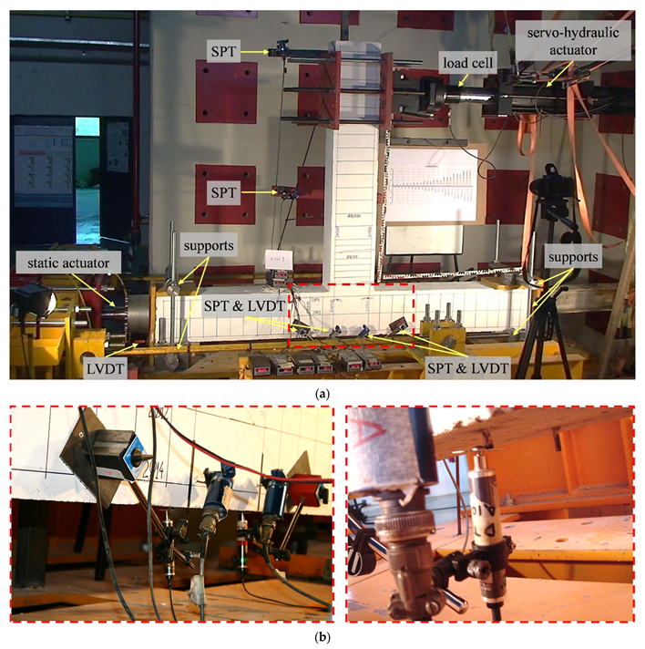
2.3. Experimental Setup and Instrumentation
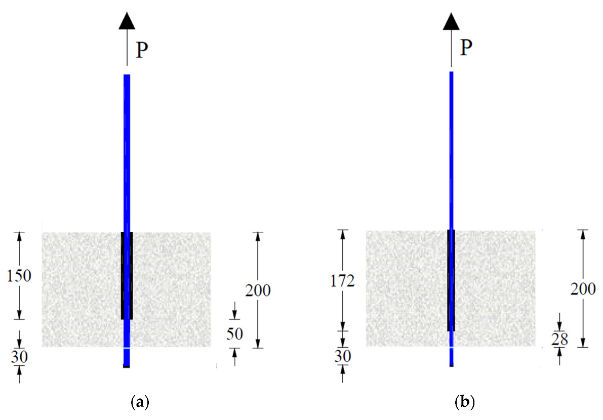
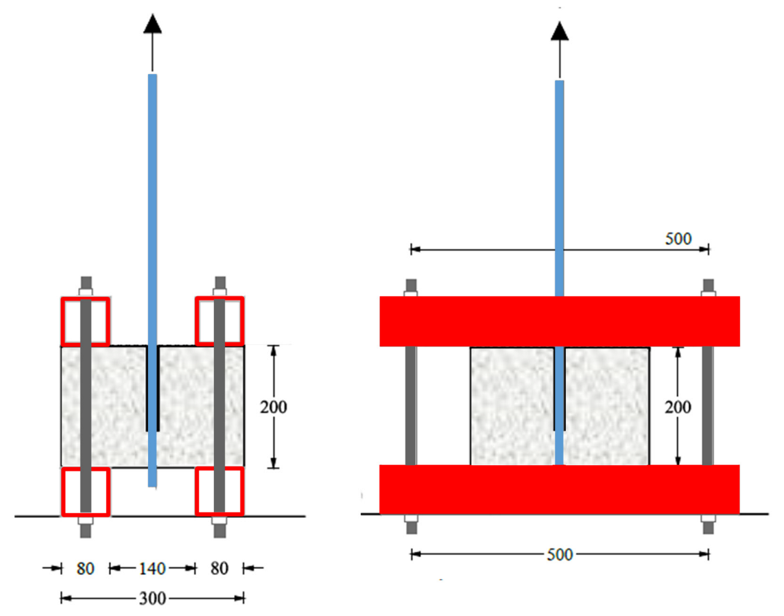
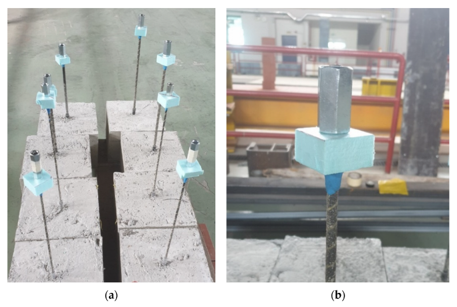
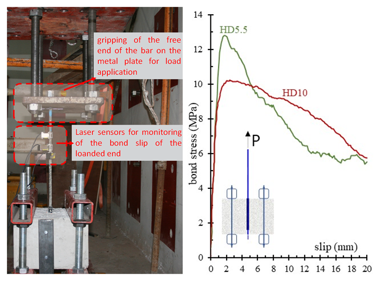
2.4. Bond Strength Evaluation—Pull-Out Tests
3. FE Model
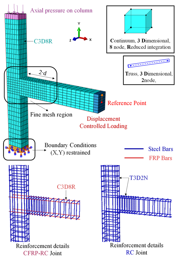
3.1. Meshing
3.2. Material Constitutive Relationship
3.2.1. Concrete
3.2.2. Steel
3.2.3. CFRP Reinforcing Bars
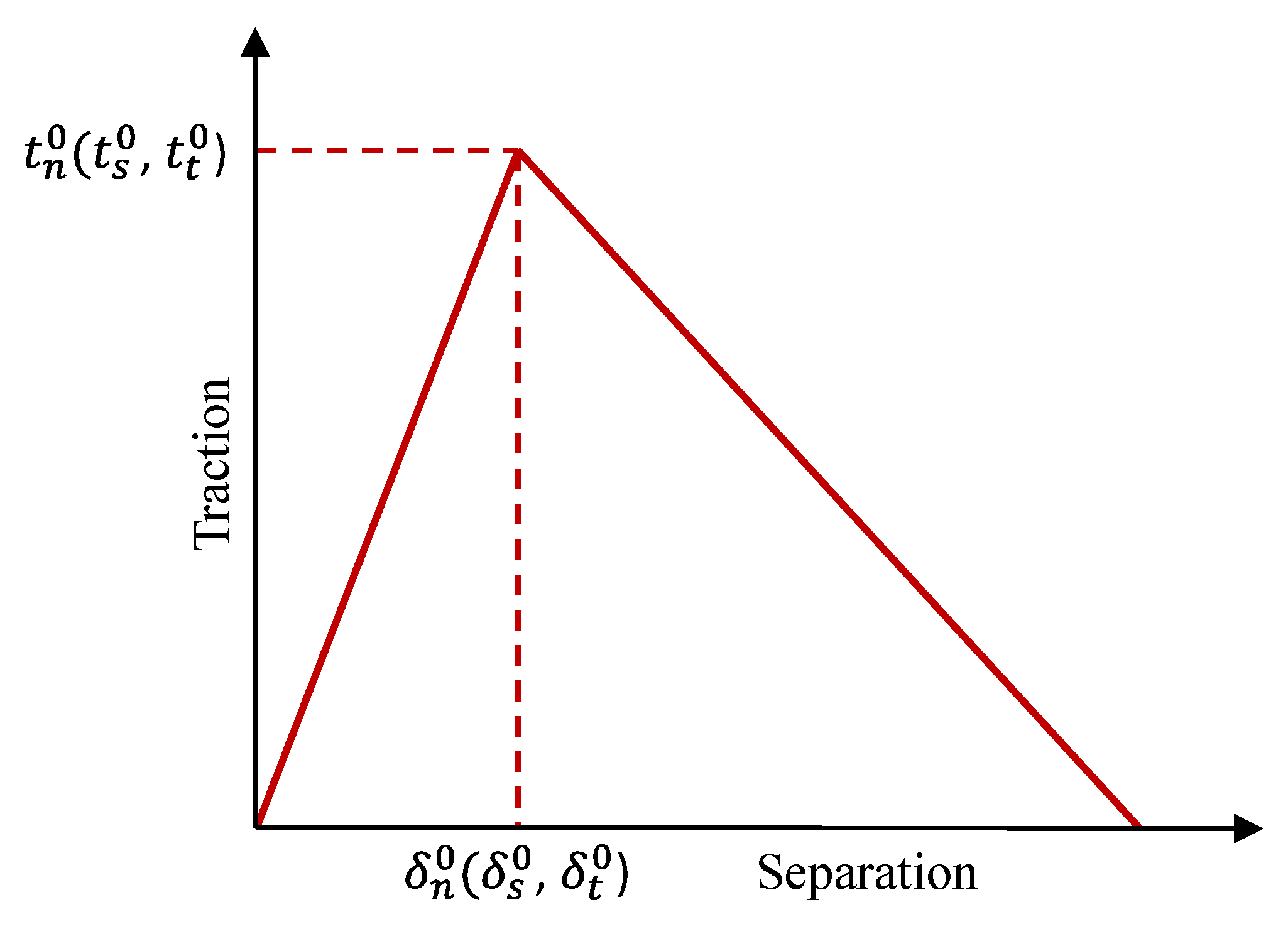
3.3. Bond Slip Interaction—Cohesive Method
3.4. Boundary Conditions and Load Application
4. Results and Discussion
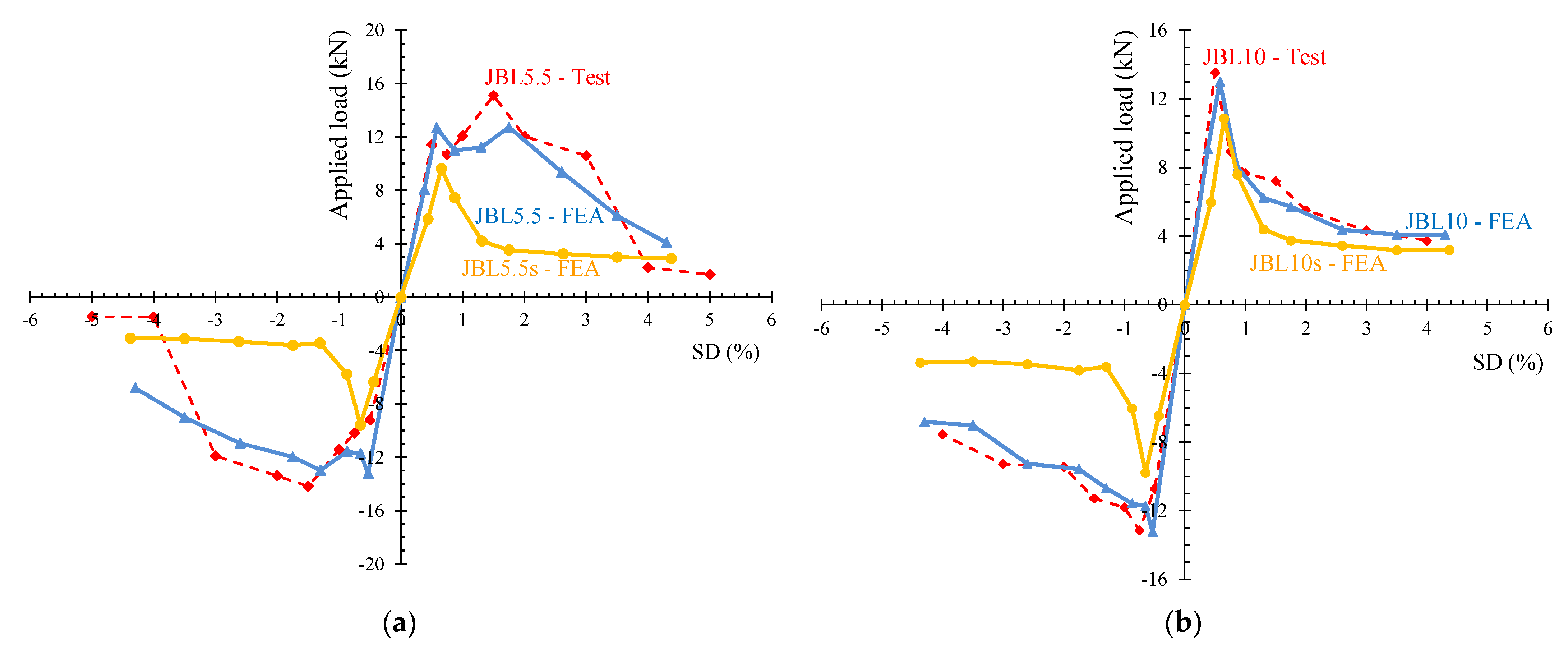
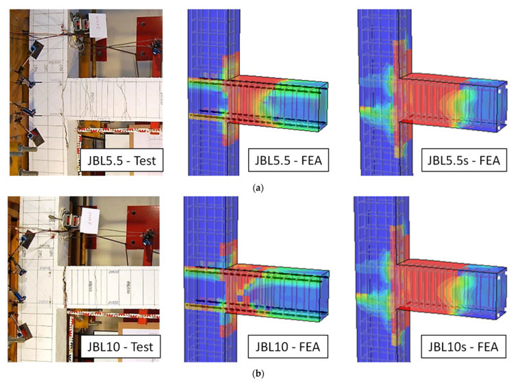
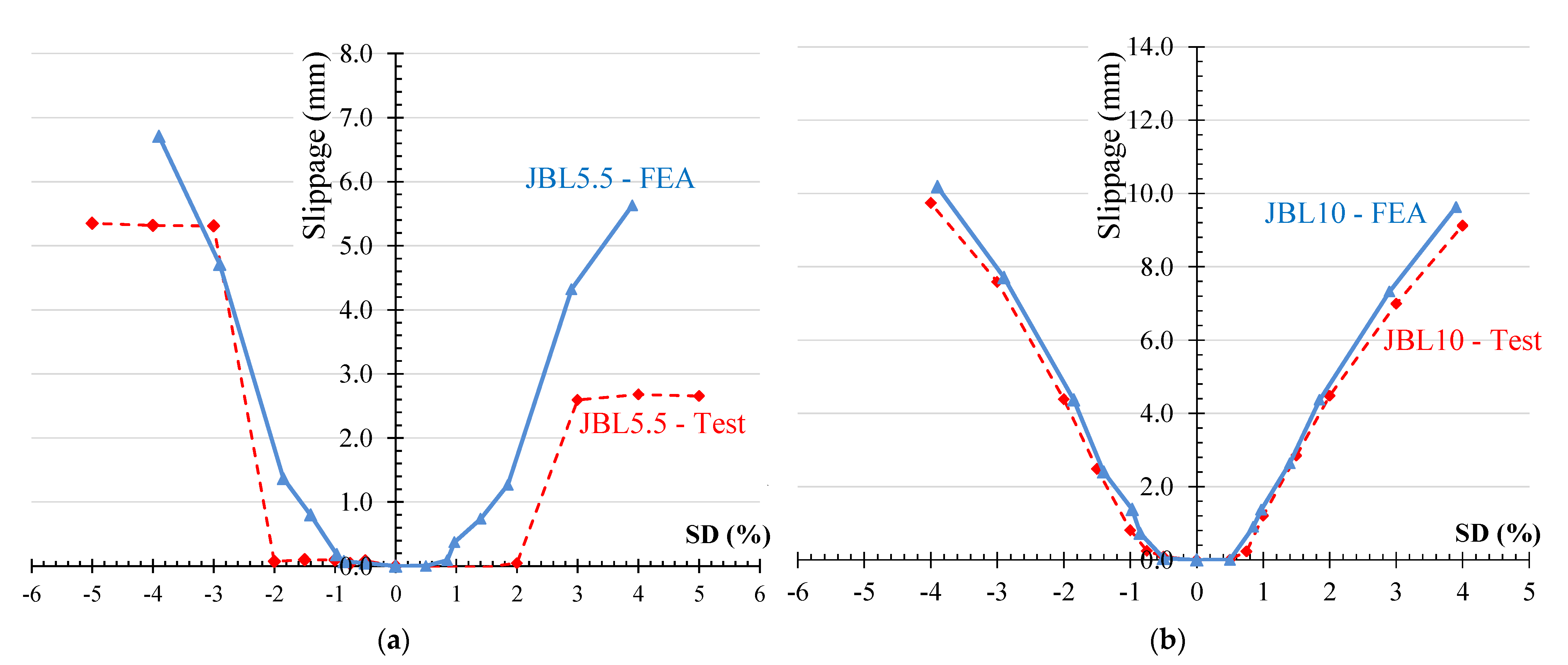
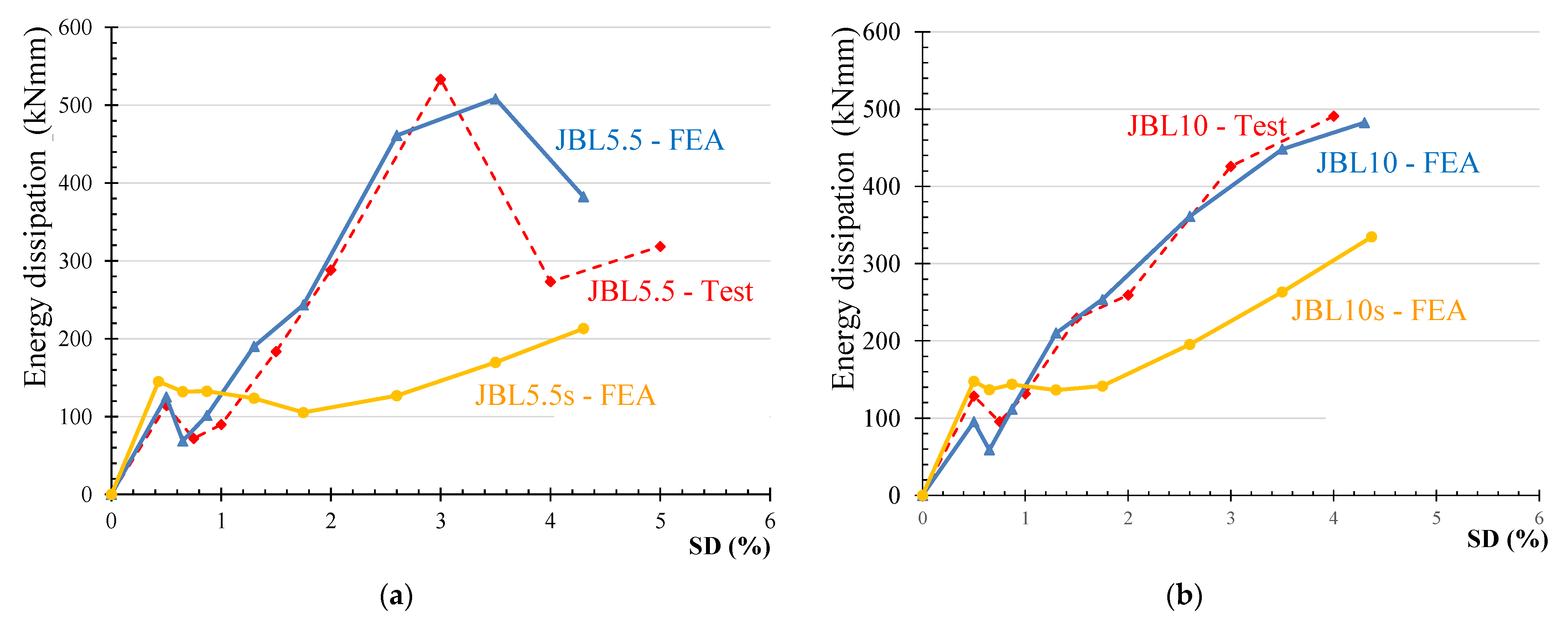
4.1. Verification of the FE Model
4.2. Use of CFRP Bars versus Conventional Steel Rebars as Beam Longitudinal Reinforcement
5. Conclusions
- The experimentally evaluated specimens’ load-carrying capacity and load-deflection response could be accurately predicted using the nonlinear FE model provided in this work. The failure mechanism, bond slip of CFRP bars and energy dissipation comparison data demonstrated that the model can properly predict the behavior of CFRP-RC joints.
- The slippage of the CFRP bars occurs after the reach of the ultimate load and thus does not significantly affect the post failure behavior and the hysteretic performance of the joint. The investigated CFRP-RC joints exhibited a residual strength higher than 35% of the flexural capacity after the occurrence of slippage. However, more investigation must be conducted in order to ensure the post failure mode and overall response of joints with CFRP longitudinal reinforcement bars.
- The dissipated energy of the CFRP-RC joints increased gradually following the specimen’s mode of failure. However, after a certain point the continuous increase up to failure is possibly attributed to the bar slippage. After the reach of an approximate SD = 0.5%, the dissipated energy of the steel-reinforced joints was significantly lower than that of the CFRP-RC joints.
Author Contributions
Funding
Institutional Review Board Statement
Informed Consent Statement
Data Availability Statement
Acknowledgments
Conflicts of Interest
References
- ACI 440R-96. Abstract of: State-of-the-art-report on fiber reinforced plastic (frp) for concrete structures. ACI Struct. J. 1995, 92, 5. [Google Scholar] [CrossRef]
- Bakis, C.E.; Nanni, A.; Terosky, J.A.; Koehler, S.W. Self-monitoring, pseudo-ductile, hybrid FRP reinforcement rods for concrete applications. Compos. Sci. Technol. 2001, 61, 815–823. [Google Scholar] [CrossRef]
- Bank, L.; Gentry, T.; Barkatt, A.; Prian, L.; Wang, F.; Mangla, S. Accelerated aging of pultruded glass/vinylester rods. In Proceedings of the Second International Conference on Composites in Infrastructure National Science Foundation, Tucson, AZ, USA, 5–7 January 1998; Volume 2. [Google Scholar]
- Rizkalla, S.H.; Mufti, A.A.; ISIS Canada (Organization). Reinforcing Concrete Structures with Fibre Reinforced Polymers; ISIS Canada: Winnipeg, MB, Canada, 2001; ISBN 978-0-9689006-6-6. [Google Scholar]
- Qureshi, J. A review of fibre reinforced polymer structures. Fibers 2022, 10, 27. [Google Scholar] [CrossRef]
- Juozapaitis, A.; Sandovič, G.; Jakubovskis, R.; Gribniak, V. Effects of flexural stiffness on deformation behaviour of steel and frp stress-ribbon bridges. Appl. Sci. 2021, 11, 2585. [Google Scholar] [CrossRef]
- Golias, E.; Vougioukas, E.A.; Wittemann, K.; Kalogeropoulos, G.I.; Karayannis, C.G. Cyclic response of RC beam-column joints strengthened with transverse steel bars and with C-FRP diagonal ties. Acta Polytech. 2022, 62, 274–282. [Google Scholar] [CrossRef]
- Karayannis, C.G.; Golias, E.; Kalogeropoulos, G.I. Influence of carbon fiber-reinforced ropes applied as external diagonal reinforcement on the shear deformation of RC joints. Fibers 2022, 10, 28. [Google Scholar] [CrossRef]
- Karayannis, C.G.; Golias, E. Full-scale experimental testing of RC beam-column joints strengthened using CFRP ropes as external reinforcement. Eng. Struct. 2022, 250, 113305. [Google Scholar] [CrossRef]
- Salleh, N.; Hamid, N.A.; Majid, M.A. Finite element modelling of concrete beams reinforced with hybrid fiber reinforced bars. IOP Conf. Ser. Mater. Sci. Eng. 2017, 271, 012093. [Google Scholar] [CrossRef] [Green Version]
- Fahmy Mohamed, F.M.; Abd-ElShafy Zainab, E.; Wu, Z. Experimental and numerical evaluation of the shear behavior of reinforced concrete T-beams with hybrid steel-FRP stirrups. J. Compos. Constr. 2017, 21, 04017007. [Google Scholar] [CrossRef]
- Kalogeropoulos, G.I.; Tsonos, A.-D.G.; Konstandinidis, D.; Tsetines, S. Pre-earthquake and post-earthquake retrofitting of poorly detailed exterior RC beam-to-column joints. Eng. Struct. 2016, 109, 1–15. [Google Scholar] [CrossRef]
- Zia, A.; Pu, Z.; Holly, I.; Umar, T.; Tariq, M.A.U.R. Development of an analytical model for the FRP retrofitted deficient interior reinforced concrete beam-column joints. Appl. Sci. 2022, 12, 2339. [Google Scholar] [CrossRef]
- Ibrahim, H.A.; Fahmy, M.F.M.; Wu, Z. Numerical study of steel-to-FRP reinforcement ratio as a design-tool controlling the lateral response of SFRC beam-column joints. Eng. Struct. 2018, 172, 253–274. [Google Scholar] [CrossRef]
- Golias, E.; Zapris, A.G.; Kytinou, V.K.; Osman, M.; Koumtzis, M.; Siapera, D.; Chalioris, C.E.; Karayannis, C.G. Application of X-shaped CFRP ropes for structural upgrading of reinforced concrete beam-column joints under cyclic loading-experimental study. Fibers 2021, 9, 42. [Google Scholar] [CrossRef]
- Golias, E.; Zapris, A.G.; Kytinou, V.K.; Kalogeropoulos, G.I.; Chalioris, C.E.; Karayannis, C.G. Effectiveness of the novel rehabilitation method of seismically damaged RC joints using C-FRP ropes and comparison with widely applied method using C-FRP sheets—Experimental investigation. Sustainability 2021, 13, 6454. [Google Scholar] [CrossRef]
- Karayannis, C.G.; Golias, E. Strengthening of deficient RC joints with diagonally placed external C-FRP ropes. Earthq. Struct. 2021, 20, 123–132. [Google Scholar]
- Karayannis, C.G.; Golias, E. Full scale tests of RC joints with minor to moderate seismic damage repaired using C-FRP sheets. Earthq. Struct. 2018, 15, 617–627. [Google Scholar]
- Ahmed, E.A.; Benmokrane, B.; Sansfaçon, M. Case study: Design, construction, and performance of the la chancelière parking garage’s concrete flat slabs reinforced with GFRP bars. J. Compos. Constr. 2017, 21, 05016001. [Google Scholar] [CrossRef]
- Karayannis, C.G.; Kosmidou, P.-M.K.; Chalioris, C.E. Reinforced concrete beams with carbon-fiber-reinforced polymer bars—Experimental study. Fibers 2018, 6, 99. [Google Scholar] [CrossRef] [Green Version]
- Murad, Y.; Tarawneh, A.; Arar, F.; Al-Zu’bi, A.; Al-Ghwairi, A.; Al-Jaafreh, A.; Tarawneh, M. Flexural strength prediction for concrete beams reinforced with FRP bars using gene expression programming. Structures 2021, 33, 3163–3172. [Google Scholar] [CrossRef]
- Jeong, Y.; Kim, W.; Gribniak, V.; Hui, D. Fatigue behavior of concrete beams prestressed with partially bonded CFRP bars subjected to cyclic loads. Materials 2019, 12, 3352. [Google Scholar] [CrossRef] [Green Version]
- Hadhood, A.; Mohamed, H.M.; Benmokrane, B.; Nanni, A.; Shield, C.K. Assessment of design guidelines of concrete columns reinforced with glass fiber-reinforced polymer bars. ACI Struct. J. 2019, 116, 193–207. [Google Scholar] [CrossRef]
- ACI-ASCE Committee 352. Recommendations for Design of Beam-Column Joints in Monolithic Reinforced Concrete Structures. ACI J. Proc. 1976, 73, 375–393. [Google Scholar] [CrossRef]
- Karayannis, C.G.; Chalioris, C.E. Capacity of RC joints subjected to early-age cyclic loading. J. Earth. Eng. 2000, 04, 479–509. [Google Scholar] [CrossRef]
- Said, A.M.; Nehdi, M.L. Use of FRP for RC frames in seismic zones: Part II. performance of steel-free GFRP-reinforced beam-column joints. Appl. Compos. Mater. 2004, 11, 227–245. [Google Scholar] [CrossRef]
- Hasaballa, M.; Amr, E.; El-Salakawy, E. Seismic behavior of beam-column joints reinforced with GFRP bars and stirrups. J. Compos. Constr. 2011, 15, 875–886. [Google Scholar] [CrossRef]
- Hasaballa, M.; El-Salakawy, E. Anchorage performance of GFRP headed and bent bars in beam-column joints subjected to seismic loading. J. Compos. Constr. 2018, 22, 04018060. [Google Scholar] [CrossRef]
- Ha, G.-J.; Cho, C.-G.; Kang, H.-W.; Feo, L. Seismic improvement of RC beam-column joints using hexagonal CFRP bars combined with CFRP sheets. Compos. Struct. 2013, 95, 464–470. [Google Scholar] [CrossRef]
- El-Mandouh, M.A.; Omar, M.S.; Elnaggar, M.A.; Abd El-Maula, A.S. Cyclic behavior of high-strength lightweight concrete exterior beam-column connections reinforced with GFRP. Buildings 2022, 12, 179. [Google Scholar] [CrossRef]
- Flenga, M.G.; Favvata, M.J. Fragility curves and probabilistic seismic demand models on the seismic assessment of RC frames subjected to structural pounding. Appl. Sci. 2021, 11, 8253. [Google Scholar] [CrossRef]
- Flenga, M.G.; Favvata, M.J. Probabilistic seismic assessment of the pounding risk based on the local demands of a multistory RC frame structure. Eng. Struct. 2021, 245, 112789. [Google Scholar] [CrossRef]
- Ghomi, S.K.; El-Salakawy, E. Seismic performance of GFRP-RC exterior beam-column joints with lateral beams. J. Compos. Constr. 2016, 20, 04015019. [Google Scholar] [CrossRef]
- Hasaballa, M.; El-Salakawy, E. Shear capacity of exterior beam-column joints reinforced with GFRP bars and stirrups. J. Compos. Constr. 2016, 20, 04015047. [Google Scholar] [CrossRef]
- Murad, Y.Z. Retrofitting interior RC beam-to-column joints subjected to quasi-static loading using NSM CFRP ropes. Structures 2021, 34, 4158–4168. [Google Scholar] [CrossRef]
- Murad, Y.Z.; RHunifat, R.; Wassel, A.L.B. Interior reinforced concrete beam-to-column joints subjected to cyclic loading: Shear strength prediction using gene expression programming. Case Stud. Constr. Mater. 2020, 13, e00432. [Google Scholar] [CrossRef]
- Balamuralikrishnan, R.; Saravanan, J. Finite element analysis of beam-column joints reinforced with GFRP reinforcements. Civil Eng. J. 2019, 5, 2708–2726. [Google Scholar] [CrossRef]
- Ghomi, S.K.; El-Salakawy, E. Seismic behavior of exterior GFRP-RC beam-column connections: Analytical study. J. Compos. Constr. 2018, 22, 04018022. [Google Scholar] [CrossRef]
- Tiwary, A.K.; Singh, S.; Chohan, J.S.; Kumar, R.; Sharma, S.; Chattopadhyaya, S.; Abed, F.; Stepinac, M. Behavior of RC beam–column joints strengthened with modified reinforcement techniques. Sustainability 2022, 14, 1918. [Google Scholar] [CrossRef]
- Balendran, R.V.; Rana, T.M.; Maqsood, T.; Tang, W.C. Application of FRP bars as reinforcement in civil engineering structures. Struct. Surv. 2002, 20, 62–72. [Google Scholar] [CrossRef]
- El-Nemr, A.; Ahmed, E.A.; Barris, C.; Benmokrane, B. Bond-dependent coefficient of glass- and carbon-FRP bars in normal- and high-strength concretes. Constr. Build. Mater. 2016, 113, 77–89. [Google Scholar] [CrossRef]
- Islam, S.; Afefy, H.M.; Sennah, K.; Azimi, H. Bond characteristics of straight- and headed-end, ribbed-surface, GFRP bars embedded in high-strength concrete. Constr. Build. Mater. 2015, 83, 283–298. [Google Scholar] [CrossRef]
- Lin, X.; Zhang, Y.X. Bond-slip behaviour of FRP-reinforced concrete beams. Constr. Build. Mater. 2013, 44, 110–117. [Google Scholar] [CrossRef]
- Zhou, Y.; Wu, G.; Li, L.; Guan, Z.; Guo, M.; Yang, L.; Li, Z. Experimental investigations on bond behavior between FRP bars and advanced sustainable concrete. Polymers 2022, 14, 1132. [Google Scholar] [CrossRef] [PubMed]
- Rolland, A.; Quiertant, M.; Khadour, A.; Chataigner, S.; Benzarti, K.; Argoul, P. Experimental investigations on the bond behavior between concrete and FRP reinforcing bars. Constr. Build. Mater. 2018, 173, 136–148. [Google Scholar] [CrossRef]
- Xue, W.; Zheng, Q.; Yang, Y.; Fang, Z. Bond behavior of sand-coated deformed glass fiber reinforced polymer rebars. J. Reinf. Plast. Compos. 2014, 33, 895–910. [Google Scholar] [CrossRef]
- Hao, Q.; Wang, Y.; He, Z.; Ou, J. Bond strength of glass fiber reinforced polymer ribbed rebars in normal strength concrete. Constr. Build. Mater. 2009, 23, 865–871. [Google Scholar] [CrossRef]
- Baena, M.; Torres, L.; Turon, A.; Barris, C. Experimental study of bond behaviour between concrete and FRP bars using a pull-out test. Compos. Part B Eng. 2009, 40, 784–797. [Google Scholar] [CrossRef]
- Sun, Y.; Liu, Y.; Wu, T.; Liu, X.; Lu, H. Numerical analysis on flexural behavior of steel fiber-reinforced LWAC beams reinforced with GFRP bars. Appl. Sci. 2019, 9, 5128. [Google Scholar] [CrossRef] [Green Version]
- Cosenza, E.; Manfredi, G.; Realfonzo, R. Behavior and modeling of bond of FRP rebars to concrete. J. Compos. Constr. 1997, 1, 40–51. [Google Scholar] [CrossRef]
- Gao, J.; Xu, P.; Fan, L.; Terrasi, G.P. Study on Bond-Slip Behavior between Seawater Sea-Sand Concrete and Carbon Fiber-Reinforced Polymer (CFRP) Bars with Different Surface Shapes. Polymers 2022, 14, 2689. [Google Scholar] [CrossRef]
- Achillides, Z.; Pilakoutas, K. Bond behavior of fiber reinforced polymer bars under direct pullout conditions. J. Compos. Constr. 2004, 8, 173–181. [Google Scholar] [CrossRef]
- Aiello, M.A.; Leone, M.; Pecce, M. Bond performances of FRP rebars-reinforced concrete. J. Mater. Civil Eng. 2007, 19, 205–213. [Google Scholar] [CrossRef]
- Roman, O.; Yuan Robert, L. Bond strength of fiber reinforced polymer rebars in normal strength concrete. J. Compos. Constr. 2005, 9, 203–213. [Google Scholar] [CrossRef]
- Tighiouart, B.; Benmokrane, B.; Gao, D. Investigation of bond in concrete member with fibre reinforced polymer (FRP) bars. Constr. Build. Mater. 1998, 12, 453–462. [Google Scholar] [CrossRef]
- Malvar, L.J.; Cox, J.V.; Cochran, K. Bergeron bond between carbon fiber reinforced polymer bars and concrete. I: Experimental study. J. Compos. Constr. 2003, 7, 154–163. [Google Scholar] [CrossRef]
- Akbas, T.T.; Celik, O.C.; Yalcin, C.; Ilki, A. Monotonic and cyclic bond behavior of deformed CFRP bars in high strength concrete. Polymers 2016, 8, 211. [Google Scholar] [CrossRef] [PubMed] [Green Version]
- ACI Committee 440. Guide for the Design and Construction of Concrete Reinforced with FRP Bars (ACI 440.1R-15); American Concrete Institute (ACI): Farmington Hills, MI, USA, 2015; p. 88. [Google Scholar]
- Dassault systèmes simulia system information. Abaqus 2017 User’s Manual; Version 6.12.1; SIMULIA: Providence, RI, USA, 2017. [Google Scholar]
- Chalioris, C.E.; Kytinou, V.K.; Voutetaki, M.E.; Karayannis, C.G. Flexural damage diagnosis in reinforced concrete beams using a wireless admittance monitoring system—Tests and finite element analysis. Sensors 2021, 21, 679. [Google Scholar] [CrossRef]
- Kytinou, V.K.; Chalioris, C.E.; Karayannis, C.G.; Elenas, A. Effect of steel fibers on the hysteretic performance of concrete beams with steel reinforcement—Tests and analysis. Materials 2020, 13, 2923. [Google Scholar] [CrossRef]
- Kytinou, V.K.; Chalioris, C.E.; Karayannis, C.G. Analysis of residual flexural stiffness of steel fiber-reinforced concrete beams with steel reinforcement. Materials 2020, 13, 2698. [Google Scholar] [CrossRef]
- Brahim, A.M.A.; Fahmy, M.F.M.; Wu, Z. 3D finite element modeling of bond-controlled behavior of steel and basalt FRP-reinforced concrete square bridge columns under lateral loading. Compos. Struct. 2016, 143, 33–52. [Google Scholar] [CrossRef]
- Mahini, S.S.; Ronagh, H.R. Numerical modelling of FRP strengthened RC beam-column joints. Struct. Eng. Mech. 2009, 32, 649–665. [Google Scholar] [CrossRef]
- Dabiri, H.; Kheyroddin, A.; Kaviani, A. A Numerical study on the seismic response of RC wide column-beam joints. Int. J. Civil Eng. 2019, 17, 377–395. [Google Scholar] [CrossRef]
- Henriques, J.; Simões da Silva, L.; Valente, I.B. Numerical modeling of composite beam to reinforced concrete wall joints: Part I: Calibration of joint components. Eng. Struct. 2013, 52, 747–761. [Google Scholar] [CrossRef]


Publisher’s Note: MDPI stays neutral with regard to jurisdictional claims in published maps and institutional affiliations. |
© 2022 by the authors. Licensee MDPI, Basel, Switzerland. This article is an open access article distributed under the terms and conditions of the Creative Commons Attribution (CC BY) license (https://creativecommons.org/licenses/by/4.0/).
Share and Cite
Kytinou, V.K.; Kosmidou, P.-M.K.; Chalioris, C.E. Numerical Analysis Exterior RC Beam-Column Joints with CFRP Bars as Beam’s Tensional Reinforcement under Cyclic Reversal Deformations. Appl. Sci. 2022, 12, 7419. https://doi.org/10.3390/app12157419
Kytinou VK, Kosmidou P-MK, Chalioris CE. Numerical Analysis Exterior RC Beam-Column Joints with CFRP Bars as Beam’s Tensional Reinforcement under Cyclic Reversal Deformations. Applied Sciences. 2022; 12(15):7419. https://doi.org/10.3390/app12157419
Chicago/Turabian StyleKytinou, Violetta K., Parthena-Maria K. Kosmidou, and Constantin E. Chalioris. 2022. "Numerical Analysis Exterior RC Beam-Column Joints with CFRP Bars as Beam’s Tensional Reinforcement under Cyclic Reversal Deformations" Applied Sciences 12, no. 15: 7419. https://doi.org/10.3390/app12157419
APA StyleKytinou, V. K., Kosmidou, P.-M. K., & Chalioris, C. E. (2022). Numerical Analysis Exterior RC Beam-Column Joints with CFRP Bars as Beam’s Tensional Reinforcement under Cyclic Reversal Deformations. Applied Sciences, 12(15), 7419. https://doi.org/10.3390/app12157419