Abstract
In this article, we present a method of analysis for 3D scanning sequences of human bodies in motion that allows us to obtain a computer animation of a virtual character containing both skeleton motion and high-detail deformations of the body surface geometry, resulting from muscle activity, the dynamics of the motion, and tissue inertia. The developed algorithm operates on a sequence of 3D scans with high spatial and temporal resolution. The presented method can be applied to scans in the form of both triangle meshes and 3D point clouds. One of the contributions of this work is the use of the Iterative Closest Point algorithm with motion constraints for pose tracking, which has been problematic so far. We also introduce shape maps as a tool to represent local body segment deformations. An important feature of our method is the possibility to change the topology and resolution of the output mesh and the topology of the animation skeleton in individual sequences, without requiring time-consuming retraining of the model. Compared to the state-of-the-art Skinned Multi-Person Linear (SMPL) method, the proposed algorithm yields almost twofold better accuracy in shape mapping.
1. Introduction
Measurement and modeling of human body movement is a research field with many visual, medical, and monitoring applications. The data source initially used by scientists was video material. Many methods of pose tracking have been developed on the basis of image sequences, but a lack of information about 3D geometry has been a significant limitation. With the emergence of cheap RGBD sensors, there has been growing interest among scientists in the analysis of unidirectional 3D scans [1,2]. A number of publications have focused on the analysis of unidirectional RGBD data, but the related methods still yield low-resolution output data and suffer from a number of problems, particularly with respect to position estimation from partial views, due to sensor noise and the problem of occlusion [2,3]. The use of 4D scanners (3D scanners capable to capture geometry multiple times per second) is cost-intensive and, so, has remained reserved to a small group of researchers who have access to the necessary equipment. With the emergence of public scanning datasets, the topic of high-resolution reconstruction of motion and deformation of the human body has gained popularity. Reconstructing the movement and shape of a body on the basis of a sequence of 3D scans is a challenging task, due to the deformations of body shape deviating from rigid body dynamics and due to the amount and nature of the input data. The measurement data take the form of a series of point clouds or triangle meshes, where the vertices are not correlated with each other between individual moments in time (i.e., the number of vertices/points can change from frame to frame). In computer graphics applications, a homogeneous topology of geometry in consecutive sequence frames is a basic requirement, in view of rendering performance. Character animation also requires the definition of an animation skeleton for skinning the mesh.
The aim of this work is to transfer changes in both the body shape and the pose of the animation skeleton on the basis of 4D scans with high spatial and temporal resolution.
The main contributions of this work are as follows:
- The development of a method to transfer human body surface deformations with geometrical accuracy better than current solutions (one of which is taken as a reference method);
- The introduction of shape maps as a tool to transfer local deformations;
- The incorporation of the Iterative Closest Point method (in the form of Point-to-Plane [4,5], with rejection and optimization, using the Levenberg–Marquadt solver [6,7]) with motion constraints for pose tracking in 4D scan sequences with high temporal and spatial resolution;
- Enabling the selection of a different mesh topology and resolution, as well as a skeleton, for each measurement sequence, without needing to retrain the model;
- Higher-resolution output meshes than state-of-the-art methods.
The remainder of the article is organized as follows: in Section 2, we give an overview of research on 4D data analysis and related topics. In Section 3.1, we provide details about the scanning data used in this work; in Section 3.2, we present the general outline of our algorithm; and, in Section 3.3 and Section 3.4, we describe the skeleton tracking and shape transfer methods, respectively, in detail. In Section 4, we present the results of an evaluation of the reconstruction quality of our method, compared to the reference method. The article concludes with a summary and description of future work, in Section 5.
2. Related Work
The appearance of low-cost RGBD cameras on the market (e.g., Kinect) has contributed to a growing interest in the subject of 4D data analysis by researchers worldwide [1,2,3,8,9,10,11,12,13,14]. The data obtained by such sensors are heavily noisy, but their low price and additional information about the depth correlated with the RGB image has created new opportunities. The authors of Reference [3] used three such sensors, together with pressure sensors placed in shoes, for pose estimation and registration of the triangle mesh. Barros et al. [13] presented a method for pose estimation based on scans of a human body, using two opposite RGBD cameras and a pre-defined skeleton model. Once the skeleton base point is initialized with Principal Component Analysis (PCA), the individual scan parts are iteratively segmented and fitted based on Expectation Maximization (EM). In the skeleton model used, the geometric relationships between individual skeleton nodes are strictly defined. Some works also focused on hand movement tracking [9,15,16]. Tsoli and Argyros [15] proposed a joint optimization method through energy minimization to track motion of hand in contact with a cloth surface. They track both deformations of the object and pose of the hand interacting with it, based on data from a Kinect2 sensor. One must also note the research in robotical environment geometry discovery [17,18,19,20]. One of the best-known groups of methods regarding this field is called Structure from Motion (SfM) [21,22], where geometry of the environment is computed from a series 2D images taken from different viewpoints. To this group belongs the algorithm developed by Glannarou and Yang [17] which focuses on the reconstruction of a surgical environment envisioned by using an endoscopic camera. The authors incorporated Unscented Kalman Filter, along with data from Inertial Measurement Unit (IMU), to achieve deformable Structure from Motion. A work by Gotardo et al. [18] solves a rigid SfM problem by estimating the smooth time-trajectory of a camera moving around an object. Introduction of a parametrization in the Discrete Cosine Transform, along with the assumption of smooth camera trajectory, enabled the researchers to perform a non-rigid SfM in the presence of occlusions.
To date, few works have focused on high-resolution data, due to high cost of obtaining such a system. One of the first collections of this type—which is available for a fee—is the CAESAR dataset (Civilian American and European Surface Anthropometry Resource Project) [23], containing about 4400 scans of different people. The pioneering work in the analysis of high-resolution 3D scans includes the SCAPE method (Shape Completion and Animation of People) [24], which is based on the model of body shape deformation as a function of the basic body shape of a given person and their pose at a specific moment. The authors presented the use of their method for the completion of unidirectional scans, as well as for the generation of mesh deformations in a sequence, based on a static scan of a person and a sequence of marker motions obtained by using the Motion Capture system. Another dataset of scans acquired with the use of a 3DMD scanner has been made publicly available, under the name Dynamic FAUST (DFAUST) [25], which has provided important motivation for research development in the field of high-resolution 4D scan analysis techniques [23,25,26,27,28,29,30,31,32,33]. This dataset consists of thousands of 3D scans of various people in different poses. The authors of the dataset developed it, using the Skinned Multi-Person Linear (SMPL) model [34], which is a trained model of various body shapes and their deformations with pose changes. Next, the authors used this model for pose and shape estimation from 2D images through the incorporation of a Convolutional Neural Network (CNN) [27,28]. The researchers also managed to develop an analogous model for infants (SMIL, Skinned Multi-Infant Linear model) using information from RGBD sequences [35,36]. Dyna [37] is a model which describes soft-tissue deformations, depending on the body shape and motion dynamics. A linear PCA sub-space is used for representation of soft-tissue deformations, whereby (as pointed out in [38]) the model has difficulty in reflecting highly non-linear deformations. DMPL (Dynamic-SMPL) [34] is based on a similar concept to Dyna, increasing the reconstruction quality by defining the model with vertices instead of triangles (as was the case in the Dyna model). SoftSMPL [38] improved on these models by introducing a non-linear deformation model and a new motion descriptor.
Further studies have involved deep learning for pose and shape estimation in 4D scans [38,39,40,41,42,43,44]. One of the directions in this area is the use of a Variational Autoencoder (VAE) to encode the 3D scan shape [40,41,42,43,44,45,46]. Litany et al. [42] used a VAE for body shape completion based on a partial view. In the aforementioned work, a neural network operates directly on the vertex positions in 3D space, instead of manually selected features (as in [44]). Jiang et al. [45,46] proposed a VAE-like network for learning the shape and pose of a human body from a sequence of triangle meshes with the same topology. For this purpose, they used measurement datasets (i.e., SCAPE, FAUST, MANO (hand Model with Articulated and Non-rigid defOrmations), Dyna, DFAUST, and CAESAR), applying to them a novel homogenous mesh registration method based on as-consistent-as-possible (ACAP) representations, proposed originally by Gao et al. [47]. Another work [48] extended the SMPL model with skeleton information, determining point features in the input data using PointNet++ and mapping them to the joints. Due to this operation, the authors improved the process of learning parameters in the SMPL model.
In summary, the existing methods for pose and shape tracking in human 3D scan sequences generally focus on the concept presented by the SMPL method, which uses a model trained on an extensive dataset of sample measurements. The works extending this model, such as SoftSMPL or the work of Jiang et al., have introduced improvements in model training, but still yield low-resolution output meshes. In these methods, it is also impossible to easily change the topology of the output mesh and the skeleton from sequence to sequence, as it is necessary to retrain the model on at least several thousand scans.
3. Materials and Methods
3.1. Materials
We used data from the Dynamic FAUST dataset [25], which presents sequences of scans of human body surface in motion in the form of a sequence of triangle meshes recorded at a frequency of 60 fps. The meshes are not correlated to each other in consecutive frames (i.e., the number of triangles and vertices changes from frame to frame). To evaluate the reconstruction quality, two sequences of 100 frames were used (Figure 1 and Figure 2).
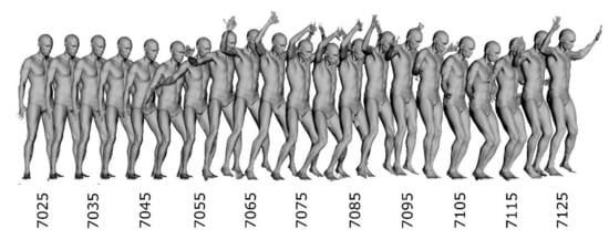
Figure 1.
Scans from input sequence “jumping jacks”. Every fifth frame of first 100 scans was used to increase readability. Numbers denote frame numbers.
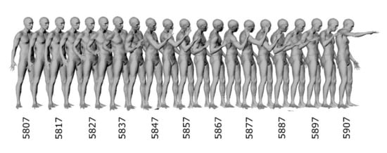
Figure 2.
Scans from input sequence “punching”. Every fifth frame of first 100 scans was used to increase readability. Numbers denote frame numbers.
3.2. Method Overview
The presented method uses a sequence of 3D scans of the human body in motion and translates this information into a computer animation of a virtual character. In the measurement dataset used, each measurement frame contains data in the form of triangle mesh; however, in the proposed process, data in the form of 3D point clouds can be used, as well.
The proposed method consists of three stages:
- Pose tracking based on the displacement of individual segments of an input scan, using a variant of the Iterative Closest Point method (hereafter referred to as tracking);
- Mapping of the scan shape in a sequence, using shape maps (hereafter referred to as mapping);
- Morphing (registration) of a uniform template mesh to the generated shape maps (hereafter called morphing).
The input data for the algorithm are as follows:
- A sequence of 3D scans of human body in motion, in the form of either meshes or point clouds;
- An animation skeleton pose for the first frame;
- A template mesh skinned to the animation skeleton for the first frame (we used automatic weights generated by the Heat Bone Weighting method [49] implemented in Blender).
The general outline of the proposed method is as follows (Figure 3): the tracking algorithm, based on two measurement frames—(t) and (t + 1)—and the skeleton for frame (t) calculates the segmentation of scan (t) for the skeleton and the pose for frame (t + 1). The scan segmentation in frame (t), together with the scan, is then used by the mapping and morphing algorithms to transfer the shape to the template mesh. After obtaining the shape maps for all the segments in a given frame, the template mesh is posed according to the skeleton in frame (t) and morphed based on the shape maps, resulting in the final triangle mesh for frame (t). This process is repeated for subsequent pairs of frames (t + 1, t + 2) (note that tracking produced the skeleton for frame (t + 1)), until the end of the measurement sequence is reached. After processing the entire scanning sequence, a series of triangle meshes with the same topology as the template mesh together with a series of skeleton poses is obtained as the output of the algorithm. The shapes of the meshes reflect the scan geometry in individual frames, while the skeleton matches the body pose change in subsequent frames of the sequence.
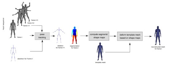
Figure 3.
Method overview. From left to right: sequence of 3D scans (gray) and skeleton for first frame; pose tracking step; resulting skeleton for frame (t + 1) and segmentation (multicolor) for frame (t); shape maps computation step; template mesh (blue); template mesh deformation step; and final reconstructed mesh for frame (t).
3.3. Skeleton Tracking
Skeleton tracking (Figure 4) operates on a sequence of the 3D scans and a skeleton for the first frame. Starting from the first frame, the current frame (t) is segmented based on the skeleton pose for that frame. Then, each of the generated segments is fitted to the point cloud of the next frame (t + 1) using the Iterative Closest Point (ICP) method. On the grounds of the obtained transform change of the segment, the transform of the relevant bone is updated by applying motion constraints specific to that bone. After analyzing all the segments (bones) in this way, the pose of the next frame (t + 1) is obtained. This procedure is iteratively repeated for successive frames of the sequence.
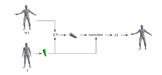
Figure 4.
Bone update procedure. From left to right: input scan for frame (t) with skeleton (bottom), scan for frame (t + 1) (upper); extracted segment for bone (B) (green) in frame (t); Iterative Closest Point (ICP) step; segment for bone (B) fitted to frame (t + 1), using ICP; constraints step; obtained transformation change of the bone (B) in frame (t + 1); and resulting skeleton for frame (t + 1), along with scan for frame (t + 1).
The purpose of segmentation (Figure 5) is to assign each point from the input scan to a skeleton bone. In the devised method, a point is assigned to the nearest bone which meets the cutoff plane, normal vector compatibility, and coplanarity conditions. Filtration with the cutoff plane consists of defining, for each bone (Bn) in the skeleton, a cutoff plane (Zn) hooked at the end of a preceding bone, Bn − 1, whose normal vector (NZn) is directed according to the sum of the vectors of the given bone (Bn) and the preceding bone (Bn − 1) (see Figure 6). A point (P) cannot be assigned to the bone (B) if it is behind this plane.
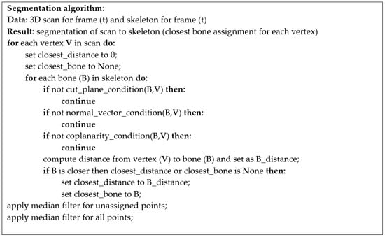
Figure 5.
The segmentation algorithm.
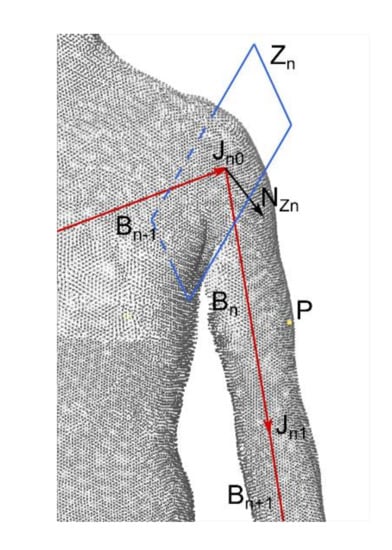
Figure 6.
Cut planes. Red arrows show bone vectors of the currently considered bone, Bn, the previous bone Bn − 1, and next bone Bn + 1. The point (P) cannot be assigned to bone Bn if it lies behind the cutting plane Zn. The plane Zn is defined by the normal vector NZn and the first joint of bone Bn (Jn0).
The normal vector parallelism condition allows us to exclude incorrect assignment of points from large segments (e.g., torso) to the bones of smaller segments (e.g., hands). According to this filtering, a point (P) may be assigned to bone (B) if the scalar product of its normal vector (N) and the radius vector (R) from the bone to the point is less than a defined threshold (Figure 7, Equation (1)):
where R is the radius vector from the bone to point (P), N is the normal vector in point (P), and α is the threshold.
R · N > α
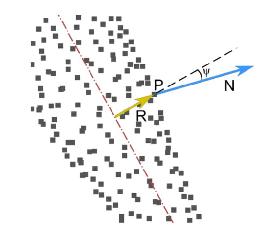
Figure 7.
Normal vector parallelism condition for point (P) with normal vector (N) and radius vector (R).
The next condition, coplanarity, is defined as follows (Equation (2)):
where R is the radius vector from the bone to point (P), N is the normal vector in point (P), B is the binormal vector in point (P), and β is the threshold.
|(R × B) · N| ≤ β
Among the bones in the skeleton that passed the three above tests against the point (P), the nearest one is selected and assigned to P. After completing the operation for all points, the values for unassigned points are populated using a median filter. Finally, a median filter with a fixed minimum number of neighbors equal to half the number of vertices in the neighborhood is applied. With this last filtration, small groups of incorrectly assigned vertices are fixed.
On the grounds of the above segmentation, the scan in frame (t) is divided into fragments corresponding to individual bones. In order to track the bone transform in the next frame, the segment for the bone (B) is fitted to the scan in frame (t + 1) using the Iterative Closest Point method. Among the many variants of this algorithm, a Point-to-Plane [4,5] version with rejection and optimization using the Levenberg–Marquadt solver [6,7] was chosen. For the estimation of the correspondence between the set of segment points and the next frame scan, a random subset of the segment’s point count is used. After establishing pairs of corresponding points in both clouds, pairs with distance further than a defined threshold are rejected. The choice of the Point-to-Plane objective function, as pointed out by Rusinkiewicz [5], ensures faster convergence than the standard Point-to-Point algorithm.
After fitting the segment to the scan in the next frame, the bone position is updated based on the input and output transforms of the segment from ICP, taking into account the motion constraints of the given bone. We consider three types of constraints: no constraint, translation constraints, and kinematic chain constraints. The first type is applicable in a case of the hip segment, from which the entire skeleton tree begins. The skeleton root can move freely, reflecting the change in position and orientation of the scanned subject. The second type, translation constraints, apply to all bones located lower in the skeleton tree, as the continuity of the bone chain must be maintained. The last type of constraint finds application in the case of leg and arm helper bones which do not take part in the segmentation process. In this case, position changes of the bone start point are allowed, but must maintain the distance to the preceding spine bone. In this way, the bone moves on the surface of a sphere with radius equal to the helper bone length and the helper bone transform is adjusted to close the skeleton chain.
3.4. Shape Mapping and Morphing
The transfer of deformations consists in the usage of shape maps, the values of which are computed based on the scan, where a template mesh is deformed according to these maps. The shape map construction schema is presented in Figure 8. The shape map of a given segment is defined by a parametric mapping in the local co-ordinate system of the segment (e.g., a spherical mapping or capsule mapping [50,51,52]). The parametric mapping converts the 3D co-ordinates of the segment measurement points into 2D co-ordinates on the shape map and the map value at these points. The value of the shape map at a given point corresponds to the third co-ordinate of the parametric mapping (i.e., the distance to the center of the mapping; Equation (3)):
where u,v are the shape map co-ordinates, r is the value of the shape map, f is the parametric mapping, x,y,z are the 3D coordinates of the segment point, and C is the mapping center.
u,v,r = f(x,y,z,C)
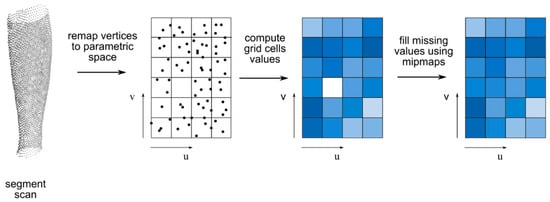
Figure 8.
Shape map construction schema. From left to right: segment scan; scan vertices remapped to parametric space (u,v) of shape map; shape map values (color coded) computed from average of points in grid cell; and shape map values (color coded) after mipmapping step to fill missing values.
Direct meaning of u,v co-ordinates depends on the parametric mapping of choice. In the example of spherical mapping as a parametric mapping, the (u,v) co-ordinates denote polar angle and azimuthal angle, respectively (Figure 9). In this case function f unrolls to following (Equation (4)):
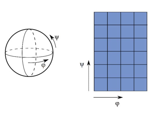
Figure 9.
Spherical mapping. Left image shows mapping shape; right image shows corresponding shape map parametrization.
After mapping all segment points from frame (t), map values in the entire domain are computed. The shape map is divided into a grid with a predefined resolution and, for each cell, the map value is established by averaging values from points falling into this cell. Next, in order to fill missing values in cells without measurement points, a mipmapping technique is used, which assigns the value of a mipmap with lower resolution for such values. This helps to avoid artifacts and holes in the morphed mesh, simultaneously maintaining the high resolution of the basis shape map and, thus, keeping the reconstruction error low. Finally, a Gaussian filter is applied to the shape map, in order to achieve smoother transitions between grid cells. Figure 10 presents a probed shape map for the arm segment in the time frame t0 of the “jumping jacks” sequence.
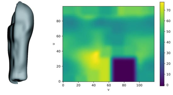
Figure 10.
Sample shape map for left arm segment in frame 7025 of the “jumping jacks” sequence. Left: mesh generated with parameter space sampling; right: shape map directly shown with color-coded values. One can see a blue rectangular area in the right bottom part of the shape map that corresponds to the upper left part of the mesh. No points were present in this area of the arm segment, and, so, the shape map values are zero. The shape map used in this example has a resolution of 100 × 120. The segment was mapped by using capsule mapping.
In order to achieve a mesh with homogenous topology in the entire sequence as output, we used a template character mesh and morphed it according to the shape maps. The template mesh had a skin correlated with the skeleton from the tracking algorithm. The skin is defined using default values for the bones, in compliance with the Heat Bone Weighting method [49] (implemented in an open-source 3D-creation software called Blender). First, the segmentation of the mesh to the skeleton in pose t0 is performed, in order to know which shape map should be used to morph each vertex from the template. Next, the mesh is posed based on the pose in frame (t), using the skinning method. The initially fitted mesh prepared this way is morphed according to the value of the shape map of the given segment (Figure 11). The vertices of the template mesh are mapped into the parametric space, and then a new value of the distance in this point is read, and a reverse mapping is applied (i.e., from the parametric to the 3D space). In order to reduce visible faults on the output mesh in the transition areas between individual grid cells of the shape map, the map value at point (u,v) is established through bilinear interpolation of values of the cells adjacent to (u,v). It should be noted that the resolution of the template mesh is independent of the resolution of the shape maps, such that it is possible to obtain preview results on a lower resolution mesh, with significantly smaller calculation time.
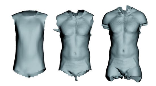
Figure 11.
From left to right: template mesh segment for torso, template after registration, and probed shape map. The map was sampled with resolution 650 × 600 in parameter space.
The process above is repeated for each frame, resulting in a series of morphed meshes with topology and vertex count congruent to the template mesh. Finally, these meshes can be applied as shape keys to the template mesh. In Figure 12, we present reconstructions of frames selected from the test sequence.
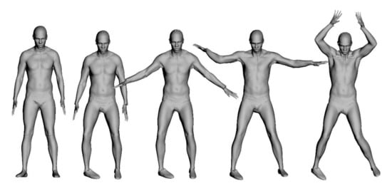
Figure 12.
Reconstructions of several frames chosen from the “jumping jacks” sequence by our method.
4. Results and Discussion
An evaluation of the fitting error was made, in order to determine the reconstruction quality between the output mesh and the input scan. The fitting error was defined as distance from a given vertex of the input scan to the nearest vertex in the reconstructed mesh. For each frame of the analyzed sequence, the reconstruction error for all vertices in the scan was computed (Table 1, full listing included in Appendix A) and then, based on that data, the average and median error for each frame was also calculated. Furthermore, in order to compare the results of our method with a state-of-the-art reference method, we carried out the analogous procedure for the reconstructed meshes shared by the authors of the Skinned Multi-Person Linear (SMPL) model method. In Figure 13 and Figure 14, we present the average and median reconstruction errors for both methods in subsequent frames of testing sequence. Figure 15 depicts reconstruction error histograms for both methods in chosen frames of both sequences. Additionally, illustrations allowing for visual assessment of the reconstruction quality in chosen frames were prepared (compare Figure 12 and Figure 16a). Figure 16b shows influence of the template mesh resolution on result reconstruction.

Table 1.
Reconstruction accuracies of our proposed method and the Skinned Multi-Person Linear (SMPL) method.
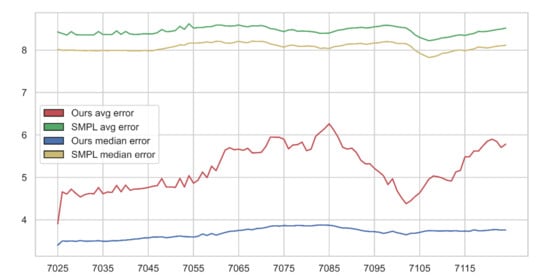
Figure 13.
Reconstruction error for “jumping jacks” sequence. X-axis denotes frame number; Y-axis denotes reconstruction error (in mm).
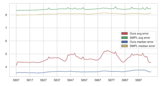
Figure 14.
Reconstruction error for the “punching” sequence. X-axis denotes frame number; Y-axis denotes reconstruction error (in mm).
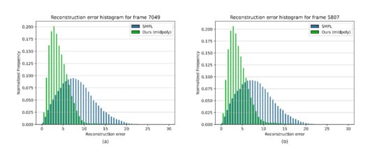
Figure 15.
Reconstruction error histogram. (a) for frame 7049 of “jumping jacks” sequence; (b) for frame 5807 of “punching” sequence.
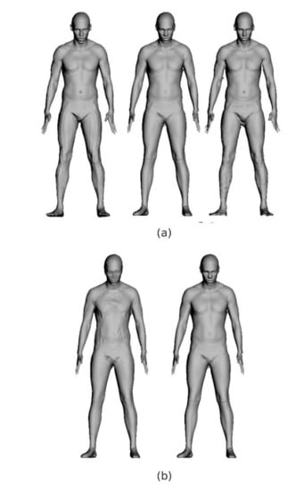
Figure 16.
(a) From left to right: SMPL reconstruction, our reconstruction, and source scan; (b) Reconstruction results for template meshes of different resolution. The left mesh has 6295 vertices, whereas the right mesh has 43,489 vertices.
On the grounds of the obtained error statistics, it can be seen that the proposed method features a better reconstruction quality than the reference method. The reconstruction errors of the proposed method were fundamentally lower than those in the case of SMPL, whereas the error distribution was shifted towards smaller values, indicating better reconstruction in a wider part of the mesh. The course of the average error in the “jumping jacks” sequence increased for frames 7065–7090 (Figure 13), where the motion was significantly faster and the arms were raised almost vertically (compare to Figure 1), increasing reconstruction difficulty in terms of arm, shoulder, and head occlusions. The median error did not change much, confirming the local character of increase of the reconstruction error in the mentioned frames. Figure 17 shows that our algorithm performs well with different or non-ideal skinning weights.
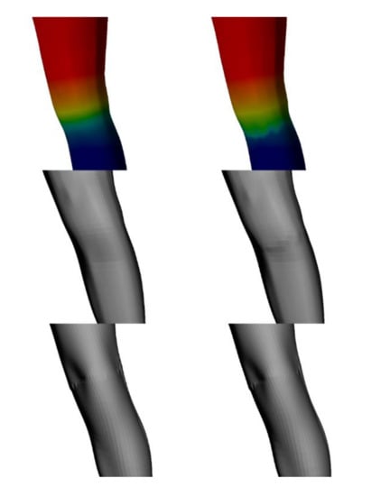
Figure 17.
Influence of change in skinning weights. Left column shows results skinning weights used in our case; right column shows results for weights changed in the knee area. From top to bottom: skinning weights, posed template mesh, and final deformed mesh.
The weaknesses of the proposed method include the uneven distribution of the resulting vertices in the end areas of the parametric mapping for given segments (Figure 18a). The reason for this lies in the mapping function, where the co-ordinates thicken around the poles, thus bringing more vertices into a similar area on the shape map. Moreover, in some frames, the output mesh was distorted due to data loss in the shape map (Figure 18b). Reconstruction based on such an erroneous map introduced artifacts in the resulting mesh. This problem was minimized by including a small fragment of adjacent segments into the shape map calculation; however, this solution is limited by the ability of the parametric mapping to map complex geometry into the 2D parametric space, without overlapping. Regarding pose tracking, one must admit, that the usage of the ICP method involves a limitation in robustness to input measurement frequency. In the presence of input data captured at a much smaller frequency than 60 fps, along with fast movement of the scanned person, the pose tracking algorithm may return inadequate pose. However, in this paper, we focus on high-resolution data and reconstruction accuracy rather than robustness to low-frequency data.
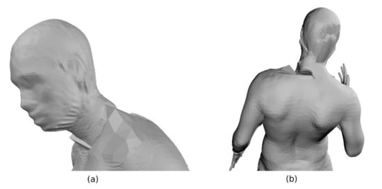
Figure 18.
(a) Vertex squeezing in collar-bone area; (b) Reconstruction artifacts on neck as a result of lacking shape map support points.
5. Conclusions and Future Work
In summary, in this paper, we have presented a method of analysis for human body 3D scan sequences that allows for the generation of skeletal animations, along with body shape deformation animations. The algorithm consists of three stages: pose tracking, shape mapping, and template mesh morphing. We performed quality tests on the obtained morphed meshes for two hundred frames from two sequences of the Dynamic FAUST dataset. We compared our method to the SMPL method by performing a similar test. The resulting reproduction quality of our method was demonstrated by the almost twice-smaller reconstruction error, compared to that of the state-of-the-art SMPL method. Moreover, an important advantage of our method is the possibility to use a template with any mesh topology and resolution, thanks to which one can generate an efficient preview animation with less detail. Furthermore, the skeleton used can also be customized.
The directions of future improvement are the transition areas between subsequent segments, where artifacts caused by the loss of data in shape map calculation (only points from a given segment and a small surrounding area participate in the shape map calculation) and vertex squeezing after parametric mapping of the shape map may appear. Furthermore, with small resolutions of the shape map, modest faults appear on the surface of the reconstructed mesh that are caused by value averaging in shape map cells.
In the future, we would like to achieve even better reconstruction quality by replacing averaging and mipmapping in the shape maps with polynomial approximation or another mathematical model. This may result in a smoother surface of the reconstructed mesh and better handling of areas without measurement points. The second field for development in the future is the template mesh morphing algorithm. Our goal will be to achieve a smoother output mesh though the application of a more advanced method for fitting the template mesh to the shape map. Last but not least, we would like to pursue more tests on robustness of the pose tracking algorithm with lower frequency capture.
Author Contributions
Conceptualization, M.N.; methodology, M.N.; software, M.N.; validation, M.N.; writing—original draft preparation, M.N. and R.S.; writing—review and editing, M.N. and R.S.; visualization, M.N.; supervision, R.S. All authors have read and agreed to the published version of the manuscript.
Funding
This research received no external funding.
Acknowledgments
We would like to thank Federica Bogo, Javier Romero, Gerard Pons-Moll, Michael J. Black, and Max Planck Institute for Perceiving Systems for making their scanning dataset named Dynamic FAUST freely available to other researchers.
Conflicts of Interest
R.S. declares no conflict of interest. M.N. is a contractor at Platige Image.
Declarations
Source code will not be available; data will not be available.
Appendix A
Table A1.
Full reconstruction accuracy results of our proposed method and the SMPL method in the “jumping jacks” sequence.
Table A1.
Full reconstruction accuracy results of our proposed method and the SMPL method in the “jumping jacks” sequence.
| Frame No. | Our Average Error | SMPL Average Error | Our Median Error | SMPL Median Error |
|---|---|---|---|---|
| 7025 | 3.90829 | 8.42681 | 3.40127 | 8.01723 |
| 7026 | 4.65882 | 8.39209 | 3.50110 | 7.99645 |
| 7027 | 4.60610 | 8.35490 | 3.49416 | 7.99738 |
| 7028 | 4.72178 | 8.43576 | 3.50169 | 7.99896 |
| 7029 | 4.62264 | 8.36426 | 3.49214 | 7.99611 |
| 7030 | 4.53709 | 8.36027 | 3.51108 | 7.99254 |
| 7031 | 4.59567 | 8.35808 | 3.49575 | 7.98607 |
| 7032 | 4.61933 | 8.35685 | 3.49693 | 7.99120 |
| 7033 | 4.61280 | 8.36075 | 3.49889 | 7.98664 |
| 7034 | 4.76028 | 8.43824 | 3.50720 | 7.98668 |
| 7035 | 4.61354 | 8.36695 | 3.49451 | 7.99287 |
| 7036 | 4.65504 | 8.36660 | 3.49415 | 7.98689 |
| 7037 | 4.64505 | 8.36913 | 3.50692 | 7.99316 |
| 7038 | 4.81100 | 8.45273 | 3.50443 | 7.99300 |
| 7039 | 4.66017 | 8.37064 | 3.51415 | 7.99213 |
| 7040 | 4.81714 | 8.43971 | 3.52152 | 7.99282 |
| 7041 | 4.69507 | 8.37888 | 3.53172 | 7.98340 |
| 7042 | 4.72680 | 8.36901 | 3.54546 | 7.98286 |
| 7043 | 4.72890 | 8.37275 | 3.55343 | 7.98082 |
| 7044 | 4.74242 | 8.38530 | 3.57312 | 7.99138 |
| 7045 | 4.76274 | 8.38182 | 3.57348 | 7.98709 |
| 7046 | 4.79098 | 8.38266 | 3.59322 | 7.98660 |
| 7047 | 4.80649 | 8.41082 | 3.59168 | 8.01049 |
| 7048 | 4.97145 | 8.48581 | 3.60001 | 8.02654 |
| 7049 | 4.76994 | 8.43516 | 3.57733 | 8.04633 |
| 7050 | 4.77586 | 8.44213 | 3.59005 | 8.06910 |
| 7051 | 4.76300 | 8.46083 | 3.60646 | 8.08881 |
| 7052 | 4.97638 | 8.56080 | 3.61767 | 8.12371 |
| 7053 | 4.77280 | 8.48920 | 3.60288 | 8.11753 |
| 7054 | 5.04108 | 8.62176 | 3.60014 | 8.16472 |
| 7055 | 4.86291 | 8.51952 | 3.59400 | 8.16442 |
| 7056 | 4.93383 | 8.53177 | 3.61046 | 8.16893 |
| 7057 | 5.12612 | 8.53452 | 3.66680 | 8.17435 |
| 7058 | 4.99398 | 8.55086 | 3.63092 | 8.19434 |
| 7059 | 5.26444 | 8.55578 | 3.67686 | 8.17435 |
| 7060 | 5.15882 | 8.58864 | 3.63931 | 8.20919 |
| 7061 | 5.40234 | 8.59133 | 3.67056 | 8.20371 |
| 7062 | 5.64279 | 8.57214 | 3.70097 | 8.16757 |
| 7063 | 5.69903 | 8.56563 | 3.72665 | 8.16115 |
| 7064 | 5.65142 | 8.56994 | 3.73463 | 8.17997 |
| 7065 | 5.66549 | 8.59214 | 3.74899 | 8.20935 |
| 7066 | 5.63848 | 8.56462 | 3.75817 | 8.18326 |
| 7067 | 5.68509 | 8.54898 | 3.77795 | 8.17640 |
| 7068 | 5.57761 | 8.57482 | 3.76521 | 8.21208 |
| 7069 | 5.57964 | 8.56847 | 3.79393 | 8.20377 |
| 7070 | 5.59075 | 8.58003 | 3.79893 | 8.20812 |
| 7071 | 5.72794 | 8.55384 | 3.81891 | 8.18958 |
| 7072 | 5.94883 | 8.50702 | 3.84818 | 8.14496 |
| 7073 | 5.94547 | 8.49459 | 3.85811 | 8.12424 |
| 7074 | 5.94496 | 8.46238 | 3.85096 | 8.09743 |
| 7075 | 5.89812 | 8.43662 | 3.86374 | 8.06921 |
| 7076 | 5.67260 | 8.47295 | 3.85796 | 8.10853 |
| 7077 | 5.76531 | 8.48272 | 3.85581 | 8.11858 |
| 7078 | 5.77159 | 8.44338 | 3.86898 | 8.09267 |
| 7079 | 5.83136 | 8.45078 | 3.86269 | 8.08869 |
| 7080 | 5.62803 | 8.44516 | 3.85725 | 8.09483 |
| 7081 | 5.66709 | 8.43735 | 3.85644 | 8.09417 |
| 7082 | 5.96711 | 8.42265 | 3.86953 | 8.08210 |
| 7083 | 6.06165 | 8.39440 | 3.87951 | 8.04085 |
| 7084 | 6.15167 | 8.39925 | 3.87508 | 8.04882 |
| 7085 | 6.26396 | 8.40132 | 3.87128 | 8.03688 |
| 7086 | 6.11804 | 8.43639 | 3.85773 | 8.07872 |
| 7087 | 5.94042 | 8.47026 | 3.83029 | 8.09297 |
| 7088 | 5.70826 | 8.48194 | 3.80498 | 8.11072 |
| 7089 | 5.66678 | 8.50780 | 3.80580 | 8.14121 |
| 7090 | 5.68833 | 8.51914 | 3.79507 | 8.14289 |
| 7091 | 5.58796 | 8.52403 | 3.77625 | 8.14797 |
| 7092 | 5.40406 | 8.53747 | 3.75247 | 8.16126 |
| 7093 | 5.31806 | 8.52352 | 3.73153 | 8.13595 |
| 7094 | 5.32031 | 8.52846 | 3.72420 | 8.14968 |
| 7095 | 5.21110 | 8.55148 | 3.71996 | 8.16910 |
| 7096 | 5.13129 | 8.55914 | 3.70812 | 8.17256 |
| 7097 | 5.03845 | 8.58343 | 3.67923 | 8.19739 |
| 7098 | 4.82968 | 8.58544 | 3.70128 | 8.19974 |
| 7099 | 4.96731 | 8.57170 | 3.73067 | 8.18905 |
| 7100 | 4.68623 | 8.54903 | 3.69563 | 8.15710 |
| 7101 | 4.51733 | 8.53533 | 3.67492 | 8.15793 |
| 7102 | 4.37930 | 8.52291 | 3.64607 | 8.15096 |
| 7103 | 4.44758 | 8.45244 | 3.68063 | 8.09297 |
| 7104 | 4.55030 | 8.35976 | 3.68393 | 7.99483 |
| 7105 | 4.63473 | 8.29928 | 3.70324 | 7.92592 |
| 7106 | 4.79126 | 8.26199 | 3.72894 | 7.87648 |
| 7107 | 4.95371 | 8.22192 | 3.74507 | 7.82597 |
| 7108 | 5.03273 | 8.23675 | 3.74165 | 7.84297 |
| 7109 | 5.01704 | 8.25925 | 3.73584 | 7.87260 |
| 7110 | 4.98381 | 8.29035 | 3.73665 | 7.92534 |
| 7111 | 4.93371 | 8.29878 | 3.73832 | 7.93425 |
| 7112 | 4.91414 | 8.31854 | 3.73557 | 7.96436 |
| 7113 | 5.12953 | 8.34595 | 3.74134 | 7.99409 |
| 7114 | 5.16400 | 8.35990 | 3.73011 | 8.00373 |
| 7115 | 5.48336 | 8.34632 | 3.73606 | 7.98486 |
| 7116 | 5.48533 | 8.37232 | 3.72759 | 8.00813 |
| 7117 | 5.62311 | 8.39371 | 3.76342 | 8.02854 |
| 7118 | 5.62082 | 8.44097 | 3.74196 | 8.07464 |
| 7119 | 5.74596 | 8.43422 | 3.74375 | 8.06058 |
| 7120 | 5.85521 | 8.44349 | 3.75184 | 8.05165 |
| 7121 | 5.89966 | 8.46217 | 3.76542 | 8.07147 |
| 7122 | 5.84843 | 8.48239 | 3.76892 | 8.09165 |
| 7123 | 5.70437 | 8.49628 | 3.75665 | 8.10090 |
| 7124 | 5.78201 | 8.51798 | 3.76182 | 8.11418 |
Table A2.
Full reconstruction accuracy results of our proposed method and the SMPL method in the “punching” sequence.
Table A2.
Full reconstruction accuracy results of our proposed method and the SMPL method in the “punching” sequence.
| Frame No. | Our Average Error | SMPL Average Error | Our Median Error | SMPL Median Error |
|---|---|---|---|---|
| 5807 | 4.10755 | 8.34520 | 3.51765 | 7.98764 |
| 5808 | 4.38241 | 8.34004 | 3.57568 | 7.97401 |
| 5809 | 4.37287 | 8.34663 | 3.56203 | 7.98234 |
| 5810 | 4.37685 | 8.36035 | 3.56737 | 8.00188 |
| 5811 | 4.35541 | 8.35037 | 3.55753 | 7.98717 |
| 5812 | 4.35682 | 8.34869 | 3.56250 | 7.98448 |
| 5813 | 4.36003 | 8.35395 | 3.57439 | 7.99814 |
| 5814 | 4.35980 | 8.35608 | 3.56466 | 7.98632 |
| 5815 | 4.34568 | 8.35993 | 3.55296 | 7.99955 |
| 5816 | 4.33170 | 8.35722 | 3.55279 | 8.00542 |
| 5817 | 4.33201 | 8.36589 | 3.55397 | 7.99869 |
| 5818 | 4.35926 | 8.36060 | 3.55231 | 7.99988 |
| 5819 | 4.35732 | 8.36433 | 3.54787 | 7.99590 |
| 5820 | 4.37303 | 8.37507 | 3.55784 | 8.00605 |
| 5821 | 4.34512 | 8.36959 | 3.53912 | 8.00202 |
| 5822 | 4.33476 | 8.36821 | 3.53422 | 8.00523 |
| 5823 | 4.33813 | 8.38498 | 3.54035 | 8.01786 |
| 5824 | 4.34382 | 8.38299 | 3.53915 | 8.02273 |
| 5825 | 4.37731 | 8.38778 | 3.54834 | 8.03060 |
| 5826 | 4.40519 | 8.40678 | 3.55417 | 8.04400 |
| 5827 | 4.44112 | 8.41216 | 3.55869 | 8.05160 |
| 5828 | 4.49795 | 8.41799 | 3.57944 | 8.04894 |
| 5829 | 4.54777 | 8.41953 | 3.59849 | 8.06309 |
| 5830 | 4.58201 | 8.42158 | 3.60857 | 8.05128 |
| 5831 | 4.77250 | 8.53519 | 3.61996 | 8.06929 |
| 5832 | 4.65823 | 8.42068 | 3.62535 | 8.04767 |
| 5833 | 4.68874 | 8.41648 | 3.63097 | 8.05728 |
| 5834 | 4.68976 | 8.42537 | 3.64087 | 8.06205 |
| 5835 | 4.70358 | 8.42031 | 3.63915 | 8.06210 |
| 5836 | 4.71411 | 8.42517 | 3.64674 | 8.05974 |
| 5837 | 4.69514 | 8.43346 | 3.65163 | 8.07723 |
| 5838 | 4.69991 | 8.45429 | 3.65495 | 8.10936 |
| 5839 | 4.66790 | 8.46388 | 3.65621 | 8.11174 |
| 5840 | 4.58720 | 8.46564 | 3.65100 | 8.10221 |
| 5841 | 4.52511 | 8.47102 | 3.65005 | 8.10613 |
| 5842 | 4.45636 | 8.47235 | 3.64220 | 8.11431 |
| 5843 | 4.43587 | 8.45785 | 3.64220 | 8.08570 |
| 5844 | 4.57028 | 8.44742 | 3.63596 | 8.07991 |
| 5845 | 4.92251 | 8.56988 | 3.66115 | 8.11222 |
| 5846 | 4.89518 | 8.47388 | 3.66104 | 8.09620 |
| 5847 | 4.97082 | 8.47607 | 3.67213 | 8.09924 |
| 5848 | 4.96422 | 8.46341 | 3.65347 | 8.08369 |
| 5849 | 4.95676 | 8.44544 | 3.64569 | 8.08262 |
| 5850 | 5.03638 | 8.54333 | 3.64345 | 8.09801 |
| 5851 | 4.81851 | 8.45332 | 3.62394 | 8.10035 |
| 5852 | 4.78894 | 8.44923 | 3.62509 | 8.08438 |
| 5853 | 4.72103 | 8.45618 | 3.62840 | 8.09312 |
| 5854 | 4.64899 | 8.46089 | 3.62474 | 8.10440 |
| 5855 | 4.60887 | 8.44353 | 3.61038 | 8.07385 |
| 5856 | 4.76739 | 8.56283 | 3.62316 | 8.08879 |
| 5857 | 4.59725 | 8.43738 | 3.62395 | 8.07007 |
| 5858 | 4.56728 | 8.42690 | 3.61229 | 8.06597 |
| 5859 | 4.57082 | 8.42371 | 3.61881 | 8.06411 |
| 5860 | 4.58205 | 8.41489 | 3.62378 | 8.03821 |
| 5861 | 4.61619 | 8.42611 | 3.62393 | 8.06020 |
| 5862 | 4.60916 | 8.43086 | 3.62822 | 8.06449 |
| 5863 | 4.57713 | 8.43630 | 3.61675 | 8.08429 |
| 5864 | 4.56960 | 8.45105 | 3.63168 | 8.08695 |
| 5865 | 4.53011 | 8.44764 | 3.62216 | 8.08853 |
| 5866 | 4.52440 | 8.46195 | 3.62851 | 8.10513 |
| 5867 | 4.53342 | 8.47570 | 3.62978 | 8.10837 |
| 5868 | 4.61739 | 8.46489 | 3.64150 | 8.11115 |
| 5869 | 4.70426 | 8.48808 | 3.64709 | 8.12363 |
| 5870 | 4.91599 | 8.50669 | 3.68213 | 8.13546 |
| 5871 | 5.07471 | 8.53795 | 3.68935 | 8.15588 |
| 5872 | 5.21286 | 8.50362 | 3.68992 | 8.14619 |
| 5873 | 5.18291 | 8.52275 | 3.68738 | 8.15126 |
| 5874 | 5.26320 | 8.50683 | 3.67175 | 8.14706 |
| 5875 | 5.21474 | 8.48310 | 3.66920 | 8.11805 |
| 5876 | 5.17838 | 8.47256 | 3.66060 | 8.11862 |
| 5877 | 5.12974 | 8.47774 | 3.65284 | 8.11165 |
| 5878 | 5.09192 | 8.48606 | 3.65486 | 8.12421 |
| 5879 | 5.02794 | 8.49248 | 3.64244 | 8.11425 |
| 5880 | 5.17144 | 8.62734 | 3.64600 | 8.12136 |
| 5881 | 4.88288 | 8.46927 | 3.66247 | 8.10742 |
| 5882 | 4.76887 | 8.46756 | 3.65255 | 8.09359 |
| 5883 | 4.62895 | 8.45531 | 3.64046 | 8.09549 |
| 5884 | 4.48490 | 8.44311 | 3.62835 | 8.07985 |
| 5885 | 4.36766 | 8.42829 | 3.62444 | 8.06102 |
| 5886 | 4.38070 | 8.43420 | 3.63192 | 8.07419 |
| 5887 | 4.45416 | 8.42748 | 3.64313 | 8.04862 |
| 5888 | 4.58274 | 8.43470 | 3.66513 | 8.07614 |
| 5889 | 4.67177 | 8.44364 | 3.68464 | 8.09177 |
| 5890 | 4.73528 | 8.45286 | 3.69060 | 8.09554 |
| 5891 | 4.81160 | 8.45742 | 3.70035 | 8.09135 |
| 5892 | 5.02276 | 8.59760 | 3.71506 | 8.12198 |
| 5893 | 4.89669 | 8.46647 | 3.73984 | 8.11216 |
| 5894 | 4.92713 | 8.47460 | 3.74742 | 8.11257 |
| 5895 | 4.94302 | 8.47617 | 3.75075 | 8.12800 |
| 5896 | 4.96842 | 8.46744 | 3.75463 | 8.11609 |
| 5897 | 4.90392 | 8.47057 | 3.75045 | 8.11155 |
| 5898 | 4.91028 | 8.45358 | 3.75586 | 8.10087 |
| 5899 | 4.88472 | 8.43944 | 3.76421 | 8.08404 |
| 5900 | 5.04229 | 8.56073 | 3.75940 | 8.08762 |
| 5901 | 4.83553 | 8.44395 | 3.75934 | 8.08745 |
| 5902 | 4.75770 | 8.42643 | 3.73491 | 8.05841 |
| 5903 | 4.81258 | 8.58391 | 3.70083 | 8.08321 |
| 5904 | 4.46718 | 8.44788 | 3.64281 | 8.08399 |
| 5905 | 4.33290 | 8.47647 | 3.61778 | 8.10652 |
| 5906 | 4.34487 | 8.50507 | 3.63095 | 8.14041 |
References
- Chen, L.; Wei, H.; Ferryman, J. A survey of human motion analysis using depth imagery. Pattern Recognit. Lett. 2013, 34, 1995–2006. [Google Scholar] [CrossRef]
- Xia, S.; Gao, L.; Lai, Y.-K.; Yuan, M.-Z.; Chai, J. A Survey on Human Performance Capture and Animation. J. Comput. Sci. Technol. 2017, 32, 536–554. [Google Scholar] [CrossRef]
- Zhang, P.; Siu, K.; Zhang, J.; Liu, C.K.; Chai, J. Leveraging Depth Cameras and Wearable Pressure Sensors for Full-body Kinematics and Dynamics Capture. ACM Trans. Graph. 2014, 33, 1–14. [Google Scholar] [CrossRef]
- Chen, Y.; Medioni, G. Object modeling by registration of multiple range images. In Proceedings of the 1991 IEEE International Conference on Robotics and Automation, Sacramento, CA, USA, 9−11 April 1991. [Google Scholar]
- Rusinkiewicz, S.; Levoy, M. Efficient variants of the ICP algorithm. In Proceedings of the Third International Conference on 3-D Digital Imaging and Modeling, Quebec City, QC, Canada, 28 May–1 June 2001. [Google Scholar]
- Levenberg, K. A method for the solution of certain non-linear problems in least squares. Q. Appl. Math. 1944, 2, 164–168. [Google Scholar] [CrossRef]
- Marquardt, D.W. An Algorithm for Least-Squares Estimation of Nonlinear Parameters. J. Soc. Ind. Appl. Math. 1963, 11, 431–441. [Google Scholar] [CrossRef]
- Habermann, M.; Xu, W.; Zollhöfer, M.; Pons-Moll, G.; Theobalt, C. LiveCap: Real-time human performance capture from monocular video. ACM Trans. Graph. 2019, 38, 1–17. [Google Scholar] [CrossRef]
- Tzionas, D.; Srikantha, A.; Aponte, P.; Gall, J. Capturing Hand Motion with an RGB-D Sensor, Fusing a Generative Model with Salient Points. In Proceedings of the 36th German Conference on Pattern Recognition, Münster, Germany, 2−5 September 2014. [Google Scholar]
- Ren, C.; Prisacariu, V.; Kähler, O.; Reid, I.; Murray, D. Real-Time Tracking of Single and Multiple Objects from Depth-Colour Imagery Using 3D Signed Distance Functions. Int. J. Comput. Vis. 2017, 124, 80–95. [Google Scholar] [CrossRef]
- Gao, Z.; Yu, Y.; Zhou, Y.; Du, S. Leveraging two kinect sensors for accurate full-body motion capture. Sensors 2015, 15, 24297–24317. [Google Scholar] [CrossRef]
- Hogue, A.; Gill, S.; Jenkin, M. Automated Avatar Creation for 3D Games. In Proceedings of the 2007 Conference on Future Play, Toronto, Canada, 15–17 November 2007. [Google Scholar]
- Barros, J.M.D.; Garcia, F.; Sidibé, D. Real-Time Human Pose Estimation from Body-Scanned Point Clouds. In Proceedings of the International Conference on Computer Vision Theory and Applications, Berlin, Germany, 11–14 March 2015. [Google Scholar] [CrossRef]
- Wei, X.; Zhang, P.; Chai, J. Accurate Realtime Full-Body Motion Capture Using a Single Depth Camera. ACM Trans. Graph. 2012, 31, 1–12. [Google Scholar] [CrossRef]
- Tsoli, A.; Argyros, A.A. Joint 3d tracking of a deformable object in interaction with a hand. In Proceedings of the European Conference on Computer Vision (ECCV), Munich, Germany, 8–14 September 2018; pp. 484–500. [Google Scholar]
- Tompson, J.; Stein, M.; Lecun, Y.; Perlin, K. Real-time continuous pose recovery of human hands using convolutional networks. ACM Trans. Graph. 2014, 33, 1–10. [Google Scholar] [CrossRef]
- Giannarou, S.; Zhang, Z.; Yang, G.Z. Deformable structure from motion by fusing visual and inertial measurement data. In Proceedings of the IEEE/RSJ International Conference on Intelligent Robots and Systems, Vilamoura, Portugal, 7–12 October 2012. [Google Scholar]
- Gotardo, P.F.U.; Martinez, A. Computing Smooth Time Trajectories for Camera and Deformable Shape in Structure from Motion with Occlusion. IEEE Trans. Pattern Anal. Mach. Intell. 2011, 33, 2051–2065. [Google Scholar] [CrossRef] [PubMed]
- Akhter, I.; Sheikh, Y.; Khan, S.; Kanade, T. Nonrigid Structure from Motion in Trajectory Space. In Proceedings of the Advances in Neural Information Processing Systems 21, Vancouver, BC, Canada, 8–11 December 2008. [Google Scholar]
- Olsen, S.I.; Bartoli, A. Implicit Non-Rigid Structure-from-Motion with Priors. J. Math. Imaging Vis. 2008, 31, 233–244. [Google Scholar] [CrossRef]
- Bregler, C.; Hertzmann, A.; Biermann, H. Recovering non-rigid 3D shape from image streams. In Proceedings of the IEEE Conference on Computer Vision and Pattern Recognition, Hilton Head Island, SC, USA, 15 June 2000. [Google Scholar] [CrossRef]
- Tomasi, C.; Kanade, T. Shape and motion from image streams under orthography: A factorization method. Int. J. Comput. Vis. 1992, 9, 137–154. [Google Scholar] [CrossRef]
- Tsoli, A.; Loper, M.; Black, M.J. Model-based anthropometry: Predicting measurements from 3D human scans in multiple poses. In Proceedings of the IEEE Winter Conference on Applications of Computer Vision, Steamboat Springs, CO, USA, 24–26 March 2014. [Google Scholar] [CrossRef]
- Anguelov, D.; Srinivasan, P.; Koller, D.; Thrun, S.; Rodgers, J.; Davis, J. SCAPE: Shape Completion and Animation of People. ACM Trans. Graph. 2005, 24, 408–416. [Google Scholar] [CrossRef]
- Bogo, F.; Romero, J.; Pons-Moll, G.; Black, M.J. Dynamic FAUST: Registering human bodies in motion. In Proceedings of the IEEE Conference on Computer Vision and Pattern Recognition (CVPR), Honolulu, HI, USA, 21–26 July 2017. [Google Scholar]
- Bogo, F.; Romero, J.; Loper, M.; Black, M.J. FAUST: Dataset and evaluation for 3D mesh registration. In Proceedings of the IEEE Conference on Computer Vision and Pattern Recognition (CVPR), Columbus, OH, USA, 23–28 June 2014. [Google Scholar]
- Bogo, F.; Kanazawa, A.; Lassner, C.; Gehler, P.; Romero, J.; Black, M.J. Keep it SMPL: Automatic Estimation of 3D Human Pose and Shape from a Single Image. In Proceedings of the European Conference on Computer Vision, Amsterdam, The Netherlands, 11–14 October 2016. [Google Scholar]
- Huang, Y.; Bogo, F.; Lassner, C.; Kanazawa, A.; Gehler, P.V.; Romero, J.; Akhter, I.; Black, M.J. Towards Accurate Marker-less Human Shape and Pose Estimation over Time. In Proceedings of the 2017 International Conference on 3D Vision (3DV), Qingdao, China, 10–12 October 2017. [Google Scholar]
- Loper, M.; Mahmoody, N.; Black, M.J. MoSh: Motion and Shape Capture from Sparse Markers. ACM Trans. Graph. 2014, 33, 1–13. [Google Scholar] [CrossRef]
- Bogo, F.; Black, M.J.; Loper, M.; Romero, J. Detailed Full-Body Reconstructions of Moving People from Monocular RGB-D Sequences. In Proceedings of the IEEE International Conference on Computer Vision (ICCV), Santiago, Chile, 7–13 December 2015; pp. 2300–2308. [Google Scholar] [CrossRef]
- Hirshberg, D.; Loper, M.; Rachlin, E.; Black, M.J. Coregistration: Simultaneous Alignment and Modeling of Articulated 3D Shape. In Proceedings of the 12th European Conference on Computer Vision, Florence, Italy, 7–13 October 2012. [Google Scholar] [CrossRef]
- Kim, M.; Pons-Moll, G.; Pujades, S.; Bang, S.; Kim, J.; Black, M.J.; Lee, S.-H. Data-Driven Physics for Human Soft Tissue Animation. ACM Trans. Graph. 2017, 36, 1–12. [Google Scholar] [CrossRef]
- Pons-Moll, G.; Pujades, S.; Hu, S.; Black, M.J. ClothCap: Seamless 4D Clothing Capture and Retargeting. ACM Trans. Graph. 2017, 36, 1–15. [Google Scholar] [CrossRef]
- Loper, M.; Mahmood, N.; Romero, J.; Pons-Moll, G.; Black, M.J. SMPL: A Skinned Multi-Person Linear Model. ACM Trans. Graph. 2015, 34, 1–16. [Google Scholar] [CrossRef]
- Hesse, N.; Pujades, S.; Romero, J.; Black, M.J.; Bodensteiner, C.; Arens, M.; Hofmann, U.G.; Tacke, U.; Hadders-Algra, M.; Weinberger, R.; et al. Learning an Infant Body Model from RGB-D Data for Accurate Full Body Motion Analysis. In Proceedings of the International Conference on Medical Image Computing and Computer-Assisted Intervention, Granada, Spain, 16–20 September 2018. [Google Scholar]
- Hesse, N.; Pujades, S.; Black, M.J.; Arens, M.; Hofmann, U.G.; Schroeder, A.S. Learning and Tracking the 3D Body Shape of Freely Moving Infants from RGB-D sequences. IEEE Trans. Pattern Anal. Mach. Intell. 2020, 42, 2540–2551. [Google Scholar] [CrossRef]
- Pons-Moll, G.; Romero, J.; Mahmood, N.; Black, M.J. Dyna: A Model of Dynamic Human Shape in Motion. ACM Trans. Graph. 2015, 34, 1–14. [Google Scholar] [CrossRef]
- Santesteban, I.; Garces, E.; Otaduy, M.A.; Casas, D. SoftSMPL: Data-driven Modeling of Nonlinear Soft-tissue Dynamics for Parametric Humans. Comput. Graph. Forum 2020, 39, 65–75. [Google Scholar] [CrossRef]
- Wang, K.; Xie, J.; Zhang, G.; Liu, L.; Yang, J. Sequential 3D Human Pose and Shape Estimation from Point Clouds. In Proceedings of the IEEE/CVF Conference on Computer Vision and Pattern Recognition (CVPR), Online, 16–18 June 2020; pp. 7275–7284. [Google Scholar] [CrossRef]
- Kingma, D.P.; Welling, M. Auto-Encoding Variational Bayes. In Proceedings of the 2nd International Conference on Learning Representations (ICLR2014), Banff, AB, Canada, 14–16 April 2014. [Google Scholar]
- Kostrikov, I.; Jiang, Z.; Panozzo, D.; Zorin, D.; Bruna, J. Surface Networks. In Proceedings of the IEEE Conference on Computer Vision and Pattern Recognition (CVPR), Salt Lake City, UT, USA, 18–22 June 2018; pp. 2540–2548. [Google Scholar] [CrossRef]
- Litany, O.; Bronstein, A.; Bronstein, M.; Makadia, A. Deformable Shape Completion with Graph Convolutional Autoencoders. In Proceedings of the IEEE/CVF Conference on Computer Vision and Pattern Recognition (CVPR), Salt Lake, UT, USA, 18–22 June 2018; pp. 1886–1895. [Google Scholar]
- Tretschk, E.; Tewari, A.; Zollhöfer, M.; Golyanik, V.; Theobalt, C. DEMEA: Deep Mesh Autoencoders for Non-Rigidly Deforming Objects. European Conference on Computer Vision (ECCV), 23–28 August 2020. Available online: https://arxiv.org/pdf/1905.10290.pdf (accessed on 24 September 2020).
- Tan, Q.; Gao, L.; Lai, Y.K.; Xia, S. Variational Autoencoders for Deforming 3D Mesh Models. In Proceedings of the IEEE/CVF Conference on Computer Vision and Pattern Recognition (CVPR), Salt Lake City, UT, USA, 18–22 June 2018; pp. 5841–5850. [Google Scholar]
- Jiang, B.; Zhang, J.; Cai, J.; Zheng, J. Learning 3D Human Body Embedding. arXiv. 2019, pp. 1–14. Available online: https://arxiv.org/abs/1905.05622v1 (accessed on 22 March 2020).
- Jiang, B.; Zhang, J.; Cai, J.; Zheng, J. Disentangled Human Body Embedding Based on Deep Hierarchical Neural Network. IEEE Trans. Vis. Comput. Graph. 2020, 26, 2560–2575. [Google Scholar] [CrossRef]
- Gao, L.; Lai, Y.-K.; Yang, J.; Ling-Xiao, Z.; Xia, S.; Kobbelt, L. Sparse Data Driven Mesh Deformation. IEEE Trans. Vis. Comput. Graph. 2019. [Google Scholar] [CrossRef]
- Jiang, H.; Cai, J.; Zheng, J. Skeleton-Aware 3D Human Shape Reconstruction From Point Clouds. In Proceedings of the IEEE/CVF International Conference on Computer Vision (ICCV), Seoul, Korea, 27 October–2 November 2019; pp. 5431–5441. [Google Scholar]
- Baran, I.; Popovic, J. Automatic Rigging and Animation of 3D Characters. ACM Trans. Graph. 2007, 26, 72. [Google Scholar] [CrossRef]
- Floater, M.S.; Hormann, K. Surface Parameterization: A Tutorial and Survey. In Advances in Multiresolution for Geometric Modelling; Springer: Berlin/Heidelberg, Germany, 2005. [Google Scholar] [CrossRef]
- Praun, E.; Hoppe, H. Spherical parametrization and remeshing. ACM Trans. Graph. 2003, 22, 340–349. [Google Scholar] [CrossRef]
- Bronshtein, I.N.; Semendyayev, K.A.; Musiol, G.; Muehlig, H. Handbook of Mathematics; Springer: Berlin/Heidelberg, Germany, 2004. [Google Scholar]
Publisher’s Note: MDPI stays neutral with regard to jurisdictional claims in published maps and institutional affiliations. |
© 2020 by the authors. Licensee MDPI, Basel, Switzerland. This article is an open access article distributed under the terms and conditions of the Creative Commons Attribution (CC BY) license (http://creativecommons.org/licenses/by/4.0/).