1. Introduction
Currently, the rehabilitation technologies are part of the strategies that facilitate the integration of people with some injury that generates disability, it is the harmonious conceptualization of technology, engineering and health [
1]. James Reswick describes the rehabilitation engineering as the application of science and technology with the purpose to reduce the limitations of individuals with disabilities [
2]. Rehabilitation engineering is multidisciplinary in bringing together professionals such as doctors, nurses, physiotherapists, occupational therapists, biologists, engineers, physicists and chemists. Indeed, the rehabilitation devices are developed by a group of specialized professionals with interdisciplinary training, such is the case of bioengineering that is the application of the knowledge gathered in a fertile balance between engineering and medical science [
3].
As already observed, the multidisciplinary environment that is generated has results in areas with high technological development entering the field of rehabilitation therapies, for example, robotics has been shown to accelerate the recuperation process [
4] and has improved the range of motion of the limbs [
5]. However, the devices have been presented as research products with low technology readiness level; therefore, they are not sufficiently compact, safe and do not have feedback for the patient or the therapist that allows them to be operated in clinical settings [
4].
These characteristics of the developments of rehabilitation technologies have results into the appearance of different methodologies approaches to create therapies devices, in [
6] describes a methodology for design an exoskeleton using a motion capture system of the trajectory of the limb from a healthy subject, for rehabilitation’s devices are important to define the specifications to calculate the design parameters of the actuator, the number of elements and the characteristics of the material [
7], the development of multidisciplinary technological devices requires a holistic methodology for planning, optimization and integration of human-centered workplaces [
8], as aforementioned each of the methodologies work like a sequence of steps but do not use the clinical context and a specialist from different disciplines working concurrently from the beginning of the design.
The methodology for the design of a rehabilitation devices must be formulated to satisfy the objectives of the rehabilitation as it is traditionally done, taking into account the regulations of medical equipment, biomechanics considerations and analysis a rehabilitation exercises that apply day to day. These considerations are immersed in the “know-how” for development of mechatronic systems and the product life-cycle management where contributes the requirements for the design such as devices modeling, simulation, validation and human-machine interfaces.
The rehabilitation devices are part of the medical equipment and they must meet specific and rigorous standards, from design to construction. The Medical Device Innovation Handbook [
9] establishes a process for the creation a medical device in which the user is defined and their needs, generating a brainstorming based on the knowledge of doctors, nurses, therapists, designers and engineers of various branches that are involved in the design of the device. The book Good Design Practice For Medical Devices And Equipment: A Framework [
10] establishes a methodology for the design and validation of medical equipment taking into account the regulation of the Food and Drug Administration (FDA) to consider the normative processes. Both emphasize the importance of gathering information from users (patients and doctors) and the monitoring of the rules that should be considered from the earliest stages.
An outstanding aspect of the methodology that is proposed in this paper is that it consider from the beginning the clinical environment through the analysis of rehabilitation sessions and interviews with users and experts, also is important include the documentation and the normative. Three aspects that stand out are the use of digital twin, use a new manufacturing techniques and the feedback of the specialists in order to avoid errors and do the processes efficiently, hence, this methodology can be implemented for the design a high impact technology such as the assistant robots.
This paper is organized as follows.
Section 2 describes the methodology which includes the phases and thirteen stages.
Section 3 shows the implementation of the methodology on the design an exoskeleton of passive rehabilitation for upper limb with a detailed description of each stage. Conclusion and future work are reported in
Section 4.
2. Methodology
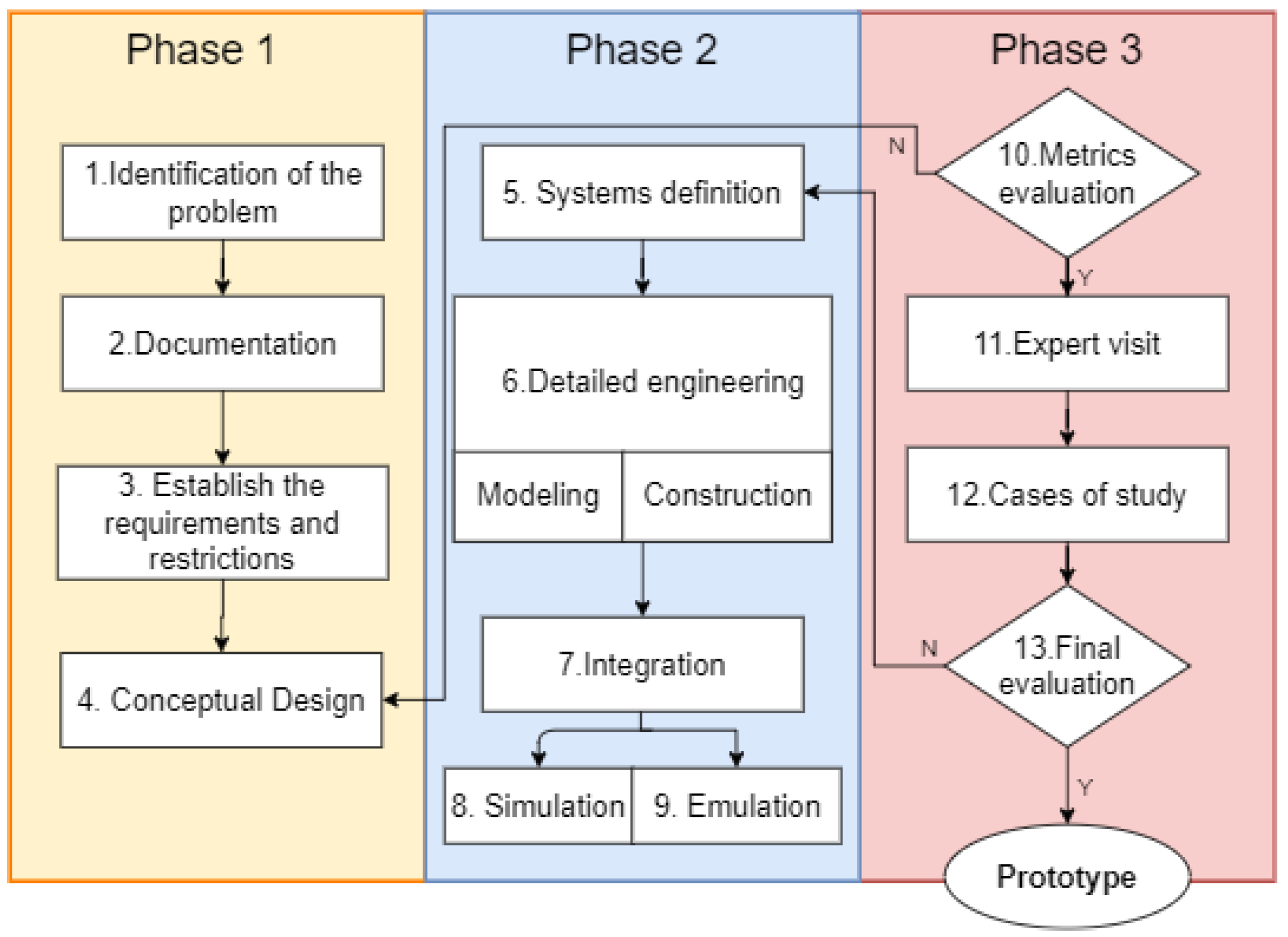
The methodology is divided into 3 phases and thirteen stages that include the construction of the system from the conception of the problem to the point where after making several iterations it is possible to make the technological transfer one step after the to consolidate a prototype.
Figure 1 shows the diagram that describes the methodology.
The three phases are made in order to divide all the process in closing task, each one represents a close cycle and the next phase can aboard it with only deliverable documentation from the previous stage.
2.1. Phase 1
The phase 1 is the initial part of the methodology it includes the context and is the first contact with the therapist and patient allowing to find niches of opportunity where technologies devices can help in the rehabilitation process. This phase is composed of 4 stages and the final product is the conceptual model and the requirements of the device.
Stage 1. Identification of the problem: The pathologies of interest are analyzed and the type of treatment that such pathology requires as passive or active rehabilitation. In this stage is identified the joints, muscles, tissues and bones involved in the medical pathology. Besides have to define the type of device want to develop.
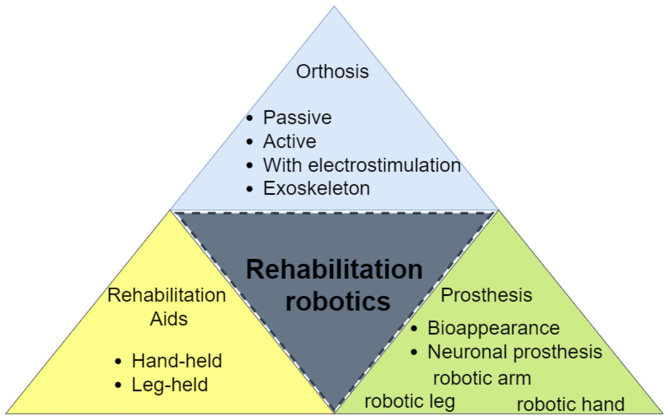
Figure 2 shows different kinds of rehabilitation robots that can be organized regarding their morphology as [
11]
Orthosis: There are the external devices that are used to improve the functionality of a body part, but they do not replace a body part only modify the structural and functional characteristics of the skeletal system.
Prosthesis: They are defined as external devices that partially or totally replace a limb it could have functionality or just have a biological appearance.
Rehabilitation Aids: These devices do not have a physical contact or a fixed point in the body, they only help during the rehabilitation protocol.
Stage 2. Documentation: To understand a problem is necessary to know the detailed context around the problem as to know the anatomical bases and how the human body works, it allows to generate an organic device that response to the patient needs. The technical context allows to analysis scientific advances to identify an opportunity to develop, improve or innovate. This stage stabilizes the project through bases with solid arguments. All this information have to be inside a database that be used in future stages.
Table 1 shows the documentation divided according to the discipline clinical and technical in order to make the interaction easier.
Stage 3. Establish the requirements and restrictions: In this stage is established the dimensions of the device and the anthropometric characteristics that must be satisfied according to the age and gender of the users and the anatomical movements performed by a healthy person. The characteristics for the movements are selected from a mechanical perspective, including the forces, speeds and accelerations. The workspace of the mechanism is requested in order to be able to performance of the rehabilitation exercises. For this methodology it is mandatory to take into account the localization of the anatomical joints in order to maintain patient safety, as well the limits of the natural range movements must be equal in the device avoiding any non-natural configuration in the patient.
Stage 4. Conceptual Design: Here appears the first approximation to the problem solution through a diorama scheme. It shows the operating principle and is possible to use augmented reality design. This is called the conceptual model that contains all the proposals of the system and the details the location of the mechanical joints of the device through a basic configuration as well the main idea of the human machine interface.
2.2. Phase 2
Phase 2 is the engineering part of the methodology, it requires technical, mathematical and physical skills, the success of this phase lies in the functionality expectations, to reach them, the design processes are detailed in a concurrent way and it is supported by technological advances in the manufacture of prototyping and a simulation based on digital twin [
14,
15] for rehabilitation devices. This phase is composed of 5 stages and the final product is the experimental physical model (EPM) and the dynamic modeling synthesis (DMS).
Stage 5. Systems Definition: For this stage is raised the design trough the creation of sets according to the function and interconnection inside the system for instance the mechanical, electronic and the interface. If it is necessary make from a set some subsets its expressed in this stage. All these sets are showed in a the structural diagram each part has an alphanumeric own identification and is showed how all the parts are connected each others. These connections sometimes represents mechanical joint or unions electrical and electronics in order to guide the design of the control and human machine interface of the device.
Stage 6. Detailed engineering: Each set is given to a different team of engineers. The information ways are planed between each team in order to maintain a communication flux. This would be done through to the database. The master guide is the structural diagram. The real dimensions, the materials for each part and each mechanical element of the system are specified even whether it is complementary as:
The methodology proposed enables the parallel develop of the next steps, the first step is create all the elements in the structural diagram in a digital environment making use of tools for dynamic modeling synthesis, it calculates the kinematics and dynamics both direct and inverse also computed the speed, joint position, torque and forces. Each set finally becomes in a block with all the dynamic behavior described waiting to interact with the rest of them. The next step consist in the construction of each component with rapid prototyping techniques that allow their assembly and feedback for the CAD and the DMS. It has been shown that working in this way brings about a faster convergence, reducing time and costs [
16].
For the interface set is necessary to select the software and firmware to work into:
Low Level Control (Programming the drivers).
High Level Control (Programming the trajectory control, movement coordination strategies, security and the interface).
Stage 7. Integration: The sets are integrated according to the information of the structural diagram to have the total DMS and the EPM, it means that are two platforms totally functional one virtual and one physical able to do experimentation in order to probe the functional principle, the requirements and restrictions. Besides is considered the assembly of actuators and sensors into the EPM.
Stage 8. Simulation: The digital twin is a virtual replica of the device that simulate the behavior of their real system [
15], it is a form of validation of the design, with the simulation system is possible to generate the product and perform the necessary iterations without affecting the final budget of the investigation. The simulation of the total model is done by the DMS. The digital twin needs the database that was created in previous stages with all the documentation.
Stage 9. Emulation: It is understood by emulation to the effect of evaluating the ranges of movements in articulations with the EPM for evaluating the precision, accuracy, resolution and load supported. It allows to fine adjustments in controller gains for each degree of freedom and its saturation limits. Regard to the high level control its design depending on the mathematical model and on the desired performance of the devices.
Furthermore, taking into account the safety protocols that the device have to follow as:
Include a fault tree analysis that it is a deductive technique to determine the sequence of faults [
17].
Include a first initial check is a path of each degree of freedom from the minor to the greatest range of movement to verify that during the development of the trajectory there are no mechanical failures.
Adequate sensors to control the robot.
2.3. Phase 3
Phase 3 is for the evaluation of the device, an expert (therapist or doctor) participation is required to evaluate the EPM to give a feedback. The evaluation is made through different strategies as measurements, usability test and experiments with healthy people. This phase is composed of 4 stages and the final product is the information enough to take the decision whether or not the EPM and DMS are viable to passes to a prototype level according to the technological transfer.
Stage 10. Metrics evaluation: It is the first formal evaluation of the device. The anatomical and functional ranges of movement identified in stage 2 are compared with the data obtaining from the EPM using different devices, furthermore it is verified that the requirements and restrictions are met. This stage establishes a security protocol for all the experiments with the EPM and it is necessary that it contains at least 3 levels of emergency stops in three different ways (mechanical, software and electric).
Stage 11. Expert visit: An expert is requested to establish tasks that emulate a therapy session with the EPM, then the evaluation and the analysis start with the performs of the rehabilitation by the device delivering a usability survey. This stage gives the chance to return to the phase 4 if the results obtained from the therapist show that is necessary an improvement in such a way the feedback is followed until the results become in the expected.
Stage 12. Cases of study: In this stage is planned a rehabilitation protocol seeking patients with the pathologies that were studied in the stage 1, if is possible use a patient that has the pathology or use a healthy user that performance the protocol. The performance is supervised by the therapist and a representative of the engineering team. If the circumstance are not able to experiments with the patient in real, the case study is introduced in the DMS to perform the tasks rehabilitation inside the simulation in a virtual environment.
Stage 13. Final evaluation: This is the last stage; therefore, a report is delivered to determine if is necessary to improve the experimental physical model or continue to a technological transfer for a prototype.
3. Design of a Rehabilitation Exoskeleton
The methodology for design of rehabilitation devices was applied to the design an exoskeleton of passive rehabilitation of upper limb called ERMIS (in Spanish, Exoesqueleto de Rehabilitación de Miembro Superior) [
18], in the next section is presented a summary of the results of the application of each stage of the methodology.
It was decided to work on the rehabilitation of the upper limb (stage 1). Regarding the state of the art it was found different robotic rehabilitation devices of the exoskeleton type upper limb some of these were mounted in wheelchairs [
19], in the floor [
20], or in a wall [
21], they are solid structures [
22]. For the state of the technique was analyzed the work done by Armeo [
23].
The documentation (stage 2) that was evaluated and taken into account was the anatomy and biomechanics of the shoulder, elbow and wrist joints. The pathologies such as stroke, brachial plexus injuries and upper limb trauma were analyzed. The performance about 340 h of rehabilitation sessions in a public health center were examined. For the regulations were taken into account the recommendations of the Federal Commission for Protection against Sanitary Risk (in Spanish, Comisión Federal para la Protección contra Riesgos Sanitarios, COFEPRIS) of their manuals of rehabilitation of upper limb, the NOM-241-SSA1-2012 [
24] dedicated to the manufacture of medical devices and ISO 13485 [
13] standard Management Systems of the Quality of Medical Equipment.
At this point it was determined that the devices do not focus on passive rehabilitation since this type of rehabilitation requires mobilization within the ranges that the injury allows the affected joint while the rest of the body remains static, these movements are executed with the help of one or two physical therapists. This is an example of one of the requirements (stage 3) that was enlisted gather the anatomical range of movements for each human joint as limits desired and others. Some of the most important restriction was the location of the joints in the exoskeleton must be aligned with the correspondent in the human’s arm. The rest of the requirements and restrictions are written inside the patent is in process.
The conceptual model (stage 4) in
Figure 3 represents a 7 Degrees of Freedom (DoF) exoskeleton each degree corresponding to the shoulder: flexion-extension, adduction and abduction, internal and external rotation; elbow flexion-extension; wrist pronation and supination, flexion-extension and radial cubital deviation. Each movement was aligned with its corresponding anatomical articulation, was proposed use of 5 linear motors and two rotational motors.
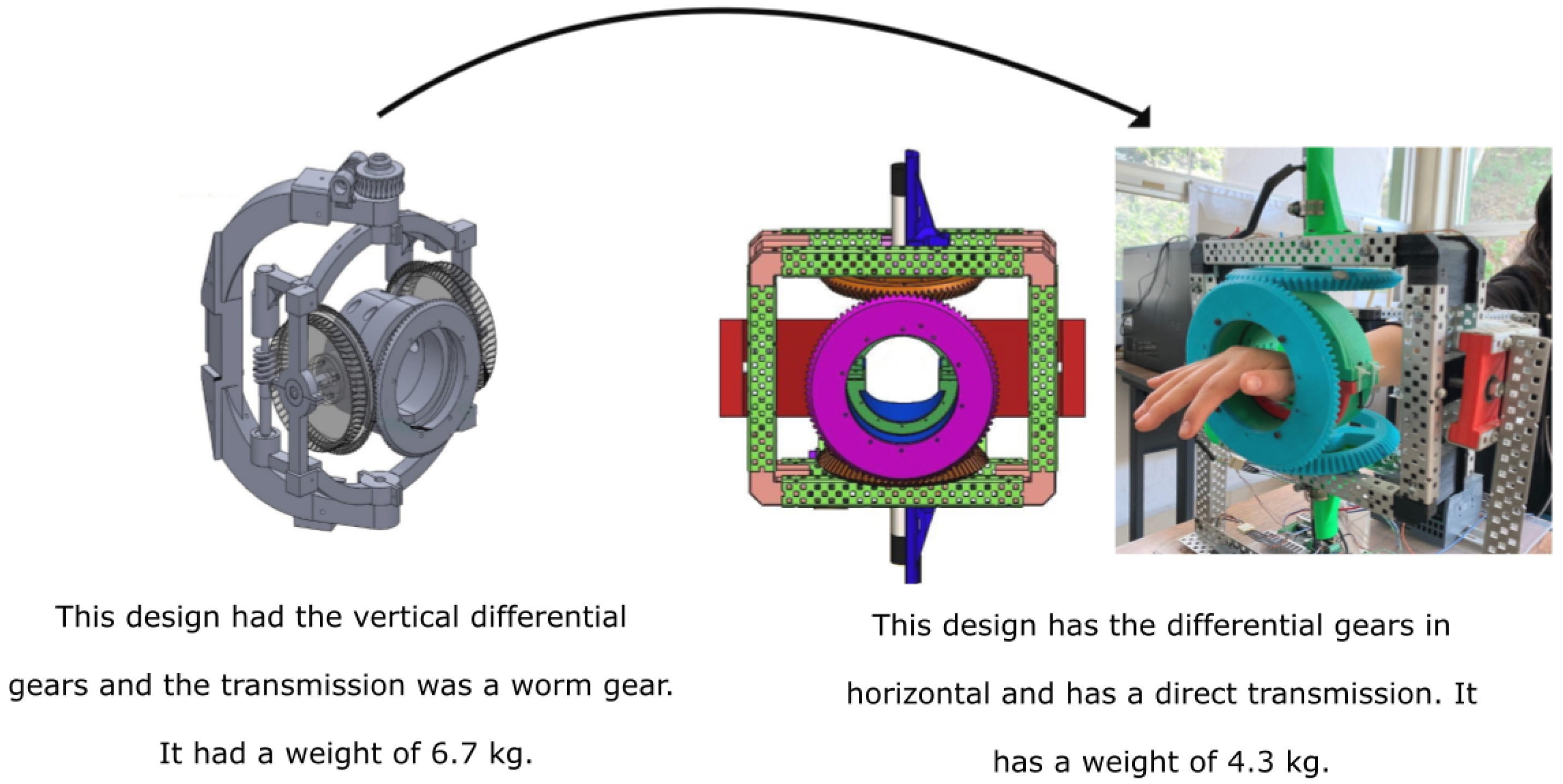
The design of the transmission of joint 5 of the arm are based on 4-bar that allow to shorten the stroke while greater the range of movement without causing any damage to the patient, ensuring that the positions are within the anatomical ranges. The joints of the wrist used 2 motors with a differential transmission with the axis of the engine aligned to the wrist joints.
To start the phase 2, the conceptual model was divided (stage 5) into three sets: mechanical, electronic control system and human-machine interface. The mechanical set is divided into four subsets: the shoulder joint, internal and external shoulder rotation, joint elbow and wrist. All of them were worked concurrently according to the structural diagram.
The implementation of the stage 6 (
Figure 4) was separated into several sub-stages in order to understand how each of the sets and subsets of the system worked in parallel. Each set was designed individually were several sequences of changes appeared.
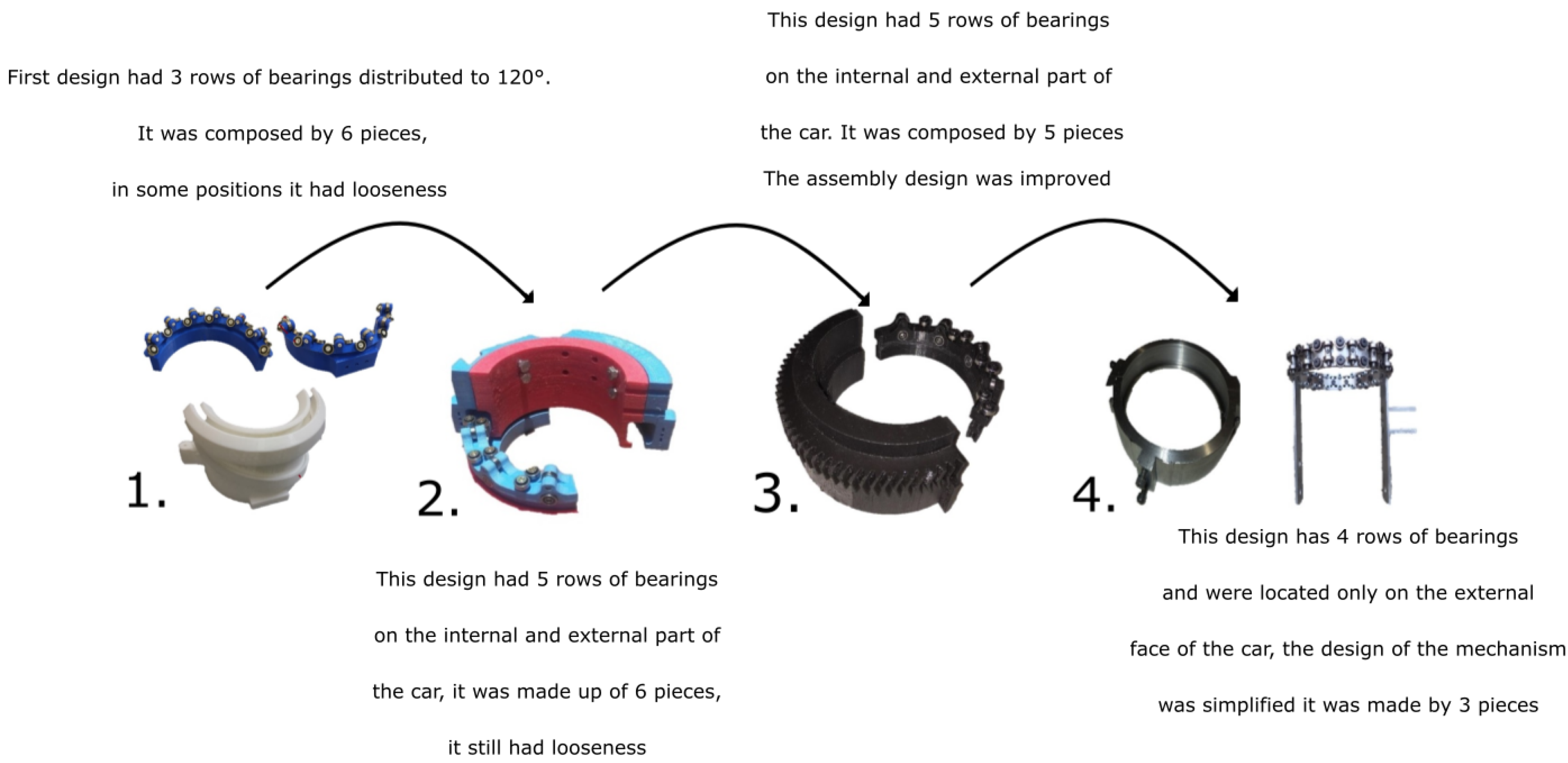
Figure 5, shows the increasing of technology readiness level (TRL) for the internal and external shoulder rotation set and
Figure 6 shows the increasing of TRL for the wrist set design.
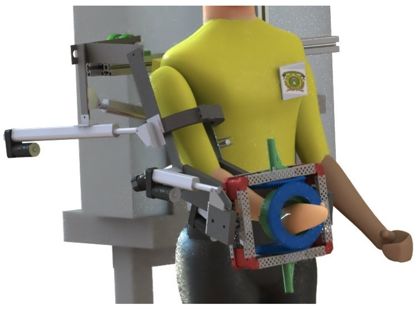
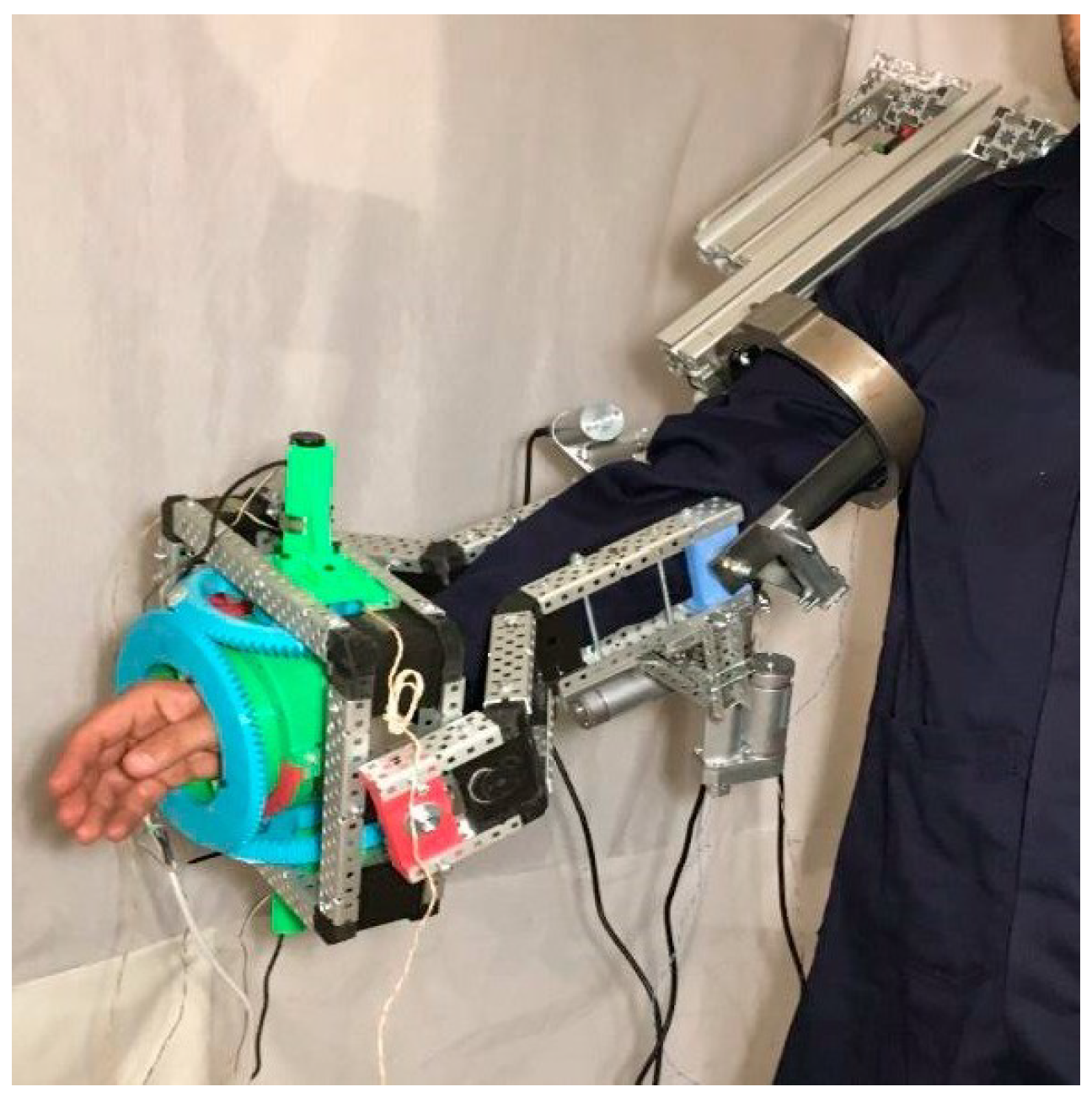
Once all the mechanics parts are finished, the experimental physical model was integrated (stage 7) according to the structural diagram for the right arm as
Figure 7 shows.
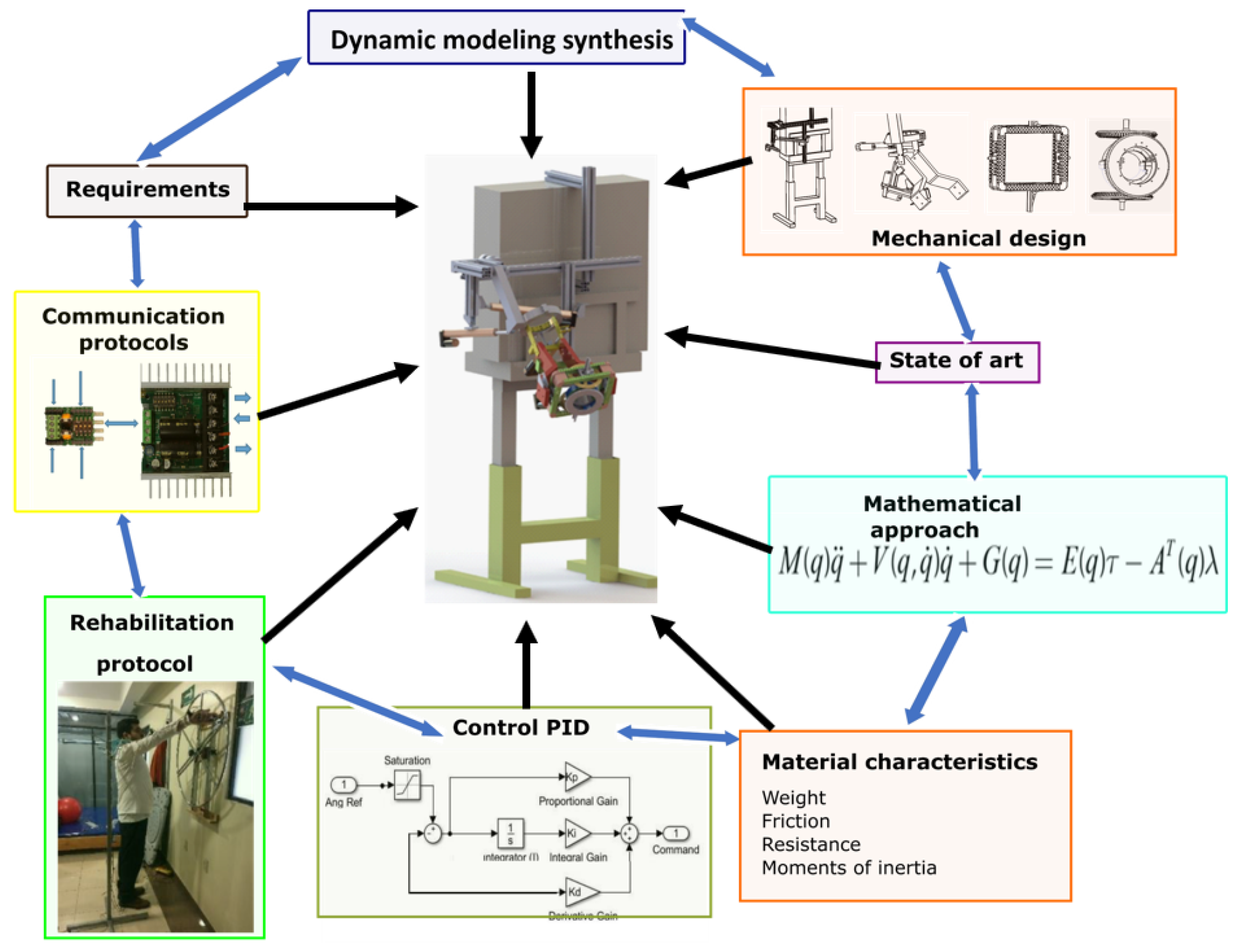
The simulation (stage 8) is inspired by digital twin methodology, this enables to foresee the expected outcomes using all the information of the previous stages in a virtual way through database.
Figure 8 shows how the DMS was integrated and simulated using Simscape and Simulink by MATLAB, the exoskeleton links were emulated through the multibody library, the dynamics of the actuators through the electric library. A PID (Proportional–integral–derivative) distributed control was implemented which allowed to performance the direct and inverse dynamics measuring accelerations, forces and moments of the exoskeleton in a virtual environment. At the same time the CPU of the exoskeleton is embedded with the algorithms from Matlab in order to make the movements coordination controlled by the screens designed inside the HMI (Human-Machine Interface) (stage 9). The design of the interface has a slide for each DoF that represent the position of the actuator and a bottom to save each configuration of all the joints. If it is necessary, the gain of each actuator control is modified. At the end of this stage its possible to control the exoskeleton and is ready to performance the proofs.
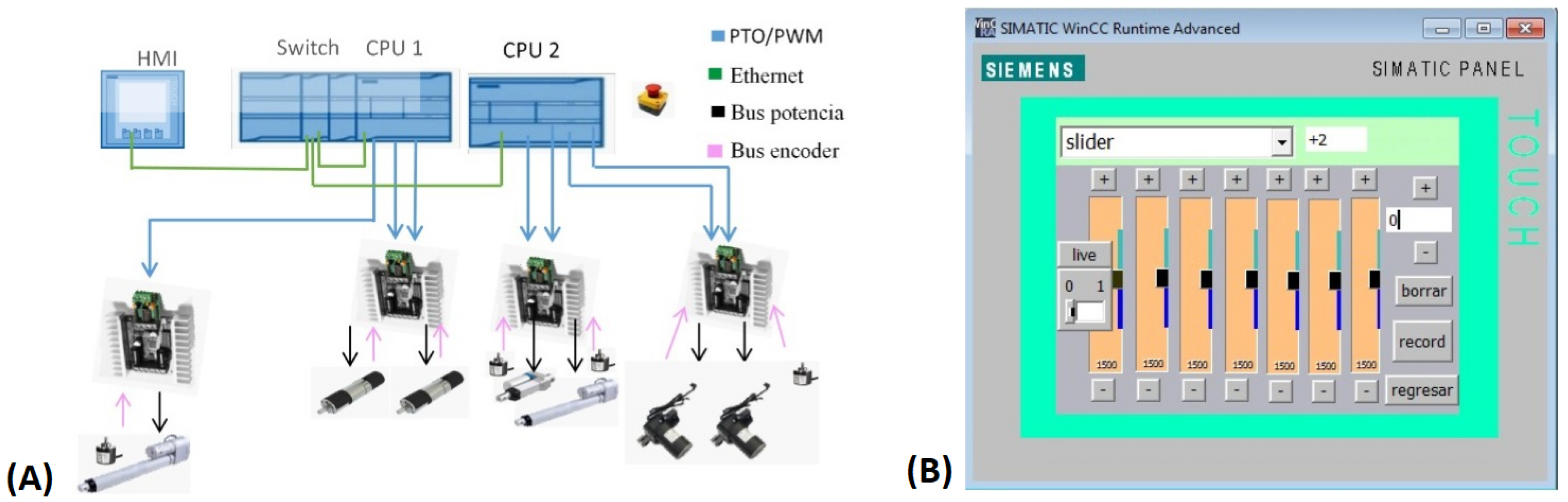
Figure 9A shows the control system and the power electronic for the actuators both are embedded in an CPU SIEMENS 1500. In phase 3, the experiments and their measurements are done. Is selected (stage 10) a healthy man with 1.85 m for height and weighing 90 kg, with an arm length of 30 cm, elbow-finger length of 46 cm and arm diameter of 34.5 cm. The test protocol is programmed through the HMI and was developed as is showed in
Figure 9B. The evaluating of the trajectory tracking and the range movement were obtained by the acquisition system specifically developed to measure the angles and trajectories of the exoskeleton currently registered with number MX/E/2019/080149. Each joint reach 100% of the functional ranges and regarding the anatomical movement range for the shoulder adduction-abduction it was covered in a 91.2%, for shoulder flexion-extension in a 96.2%, for internal and external shoulder rotation in a 97.4%, for elbow flexion-extension in a 93.6% and for wrist flexion-extension in a 96.6%, on average the ERMIS is able to follow in 95% the trajectories according to anatomical and functional ranges established in [
25].
According to the Handbook of Usability Testing [
26], the main objective of these tests is to collect information on the perception of design that users have, there are different approaches when performing functionality tests, the objective of performing a test of usability in this methodology is to analyze the perception that specialists have with the design of the exoskeleton (stage 11). The usability analysis consisted of three phases:
Pre-test: A survey focused on the academic level of the users and their workload during the rehabilitation sessions.
Test: This phase the specialists analyzed the design of the exoskeleton and its components such as the screen, safety buttons, patient support, etc. and then a task was performance which consisted of simulating a rehabilitation session without a patient so that they could analyze the task analysis and device functionality.
Post-test: This phase the specialists asked to design engineers questions in order to know which aspects are intuitive and which require prior introduction, they also made more specific comments on the design.
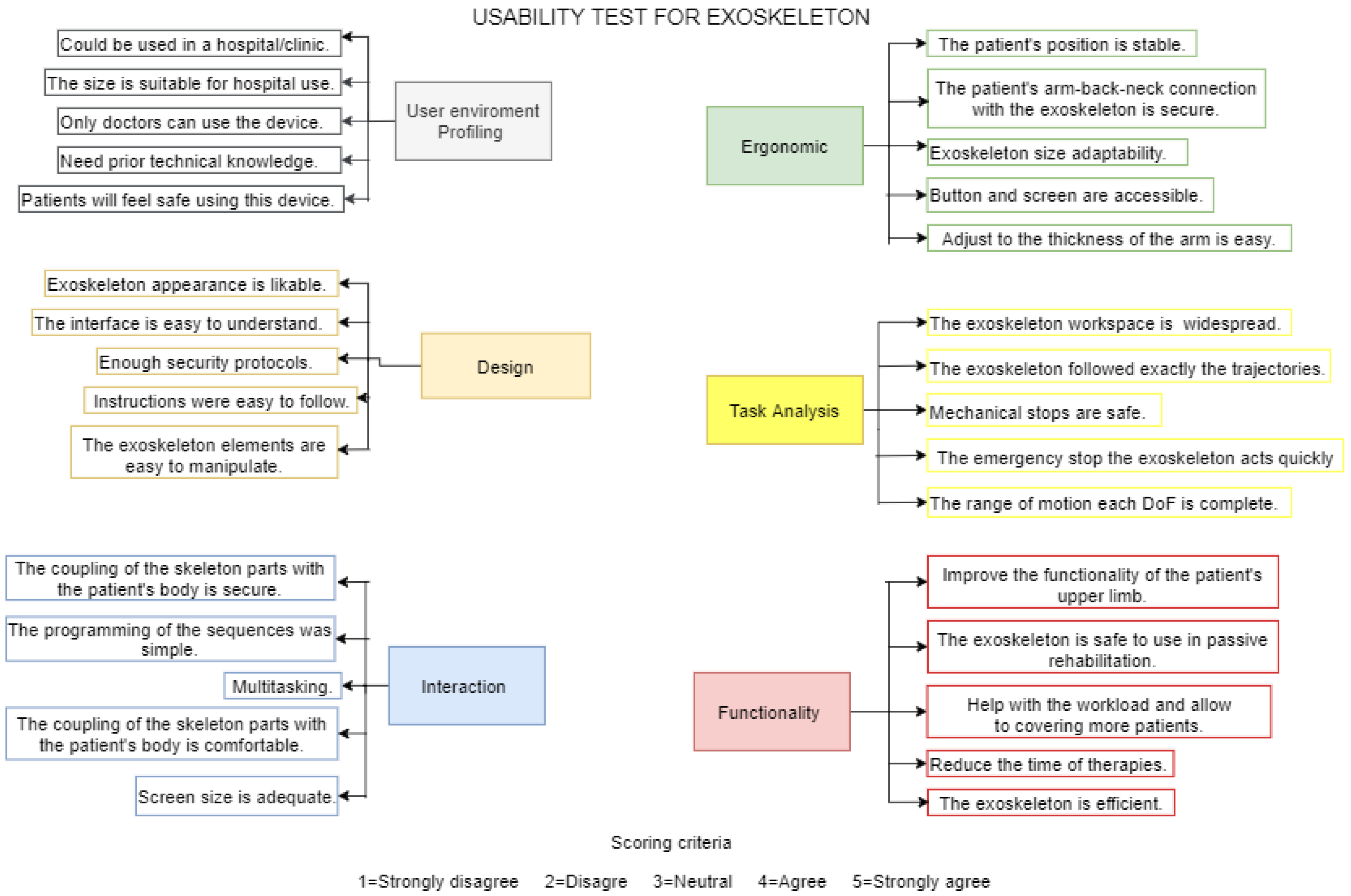
The usability test consisted of six sections as
Figure 10 shows, the first section “user environment profiling” takes into account issues as interaction with the patient regarding a clinical environment. The second section “design” lets know if the exoskeleton design is attractive, safe and easy to use. The third section “interaction” encompass factors such as the coupling of the exoskeleton to the body. The fourth section “ergonomic” is analyzed the components adaptability and the position of the patients and therapists. The fifth section tackle the task analysis considering factors such as the range of movement, mechanical stops and safety. At the end the sixth section cover the functionality evaluation in order to know if the device could be implemented in health centers to support physiotherapists. Each section contained five questions, as answers to each question, the Likert scale suggested in [
26] was used, which consists of the following options: strongly disagree, disagree, neutral, agree and strongly agree. For each answer was assigned a scoring criteria as shown in
Figure 10, this to make a statistical analysis of the positions of specialists regarding the design and use of the exoskeleton.
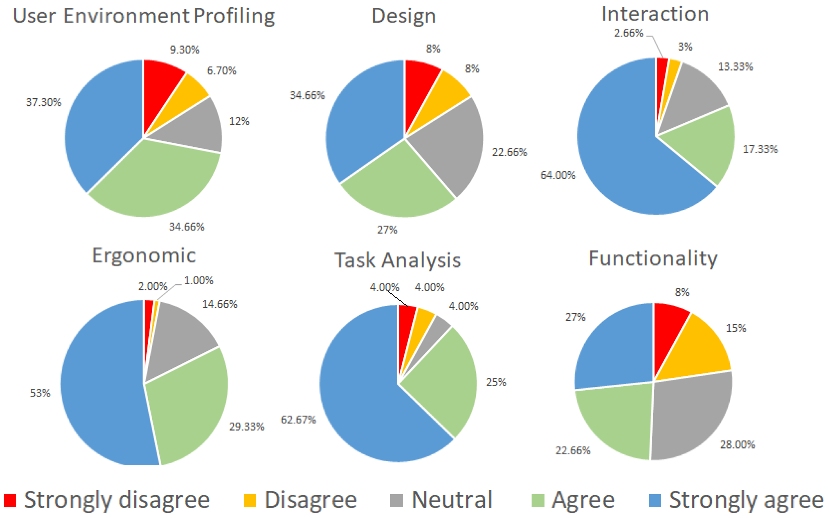
This analysis was applied to 12 physiotherapists and 3 doctors,
Figure 11 shows the percentage of the five scores for each section.
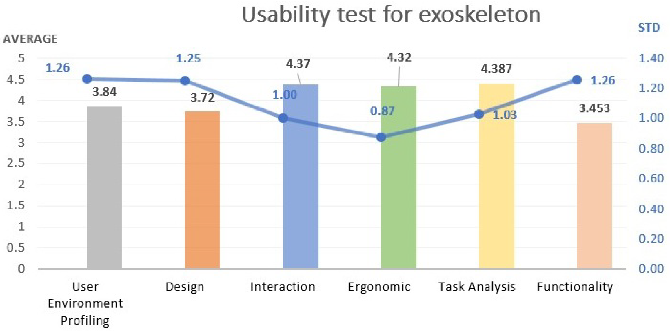
As shown in
Figure 12, the highest score was given in the task analysis. The doctors and the therapists consider this section the most important topic when evaluating a medical device because it determines the usefulness of the exoskeleton. The lowest score was given in the functionality because for this section is required to do experimentation with patients to establish the rehabilitation treatment. Overall, the evaluation result was acceptable getting an average of 4.015; for this reason, it was considered that the exoskeleton development can continue to the next stage, keeping its current technical specifications.
Two physiotherapists who approved the analysis of usability was invited to work into a pair of study cases (stage 12). Is proposed a healthy patient for emulate a rehabilitation protocol for shoulder-elbow and elbow-wrist in order to evaluate the tracking of ERMIS. Develop of the case studies always were under the guidance of the safety protocol establishes by the regulations inside [
13,
24]. One of the most important point was that the physiotherapist in charge and one of the design engineer were present during the sessions of rehabilitation, before the sessions it was necessary to verify the presence and functionality of an emergency stop button and the electrical safety.
Depending on the protocol the tasks, the intensity of the training and speed has been adapted individually.
Case of study 1: A 39-year-old male is performed a rehabilitation routine for shoulder-elbow, the rehabilitation protocol simulated that the arm rotates like a rudder.
Figure 13(1–3) shows the data acquisition from rehabilitation therapy and
Figure 13(4–6) shows the rehabilitation protocol with the exoskeleton. The protocol includes movements for shoulder and elbow joints.
At all time the training was supervised by a physiotherapist, providing assistance and instructions for the patient and a medical doctor in charge of documentation and supervision.
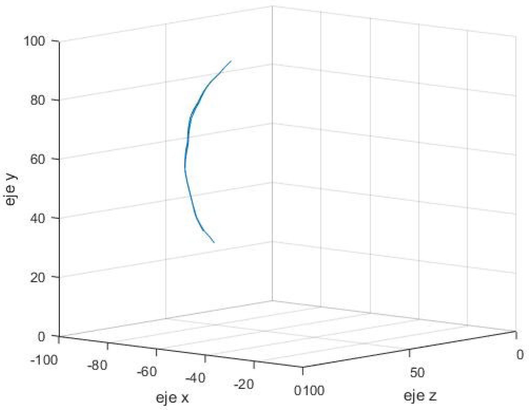
Figure 14 shows the trajectory of the end-effector of the exoskeleton when it performed the rehabilitation protocol. The exoskeleton is able to follow the rudder trajectory.
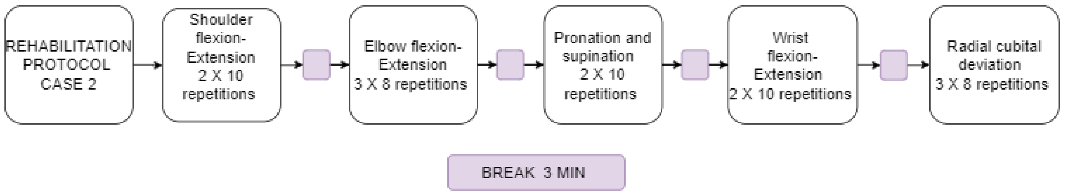
Case of study 2: A 47-year-old female is performed a rehabilitation routine for elbow-wrist. The
Figure 15 shows the protocol that was analysis in 20 repetitions. The rehabilitation protocol includes independent movements for each of the elbow and wrist joints. The procedure consists of selecting the joint to be worked on (wrist), immobilizing the rest of the joints of the arm by means of bandages or with the participation of a second therapist, but in this case the therapy only use the exoskeleton for immobilizing the rest of the joints (Shoulder and elbow).
Table 2 shows the error that the exoskeleton presents during the performance of the protocol against the data acquisition for each case of study. Furthermore, it shows the range of motion for each DoF.
For stage 13, a summary of the previous stages is presented, emphasis in the cases of study and usability. A meeting was held with members of each team together with the team of specialists and an opinion was issued stating that the exoskeleton works for passive rehabilitation but the materials that were chosen are not the best, a budget is suggested to update mechanical elements with other types of materials. In addition, a recommendation for improve the design of the interface in HMI that should be more intuitive for the therapist. It is suggested that a more extensive study be made regarding compatibility for patients of different sizes, because the range of sizes that the exoskeleton can use is unknown.
4. Conclusions
This methodology is highlighted by the level of information that it manages from the perspective of the patient, therapist and the clinical environment not only from the technological view also includes the contextual view, this fact enabled the device to be accepted in 87.94% according to usability criteria. The methodology allowed to develop an EPM of an exoskeleton in 2 years with limited resources. The information is stored in a database and is embedded in a virtual environment inspired by the methodology of digital twin.
The methodology allows to identify specific needs which caused the elements and the exoskeleton itself to be an original design with a patent registration MX/F/2018/000467 also the detailed study of the documentation stage produce the registration of a wire distribution system EXOSEP with registration MX/F/2019/002548.
The use of technological know-how from other areas such as the industrial allowed to use an industrial CPU within the medical area, which was robust enough to be able to performance a rehabilitation therapy.
The methodology integrates the validation of the exoskeleton through the analysis of case of studies, for the exoskeleton its demonstrated that is possible to reproduce the rehabilitation exercises in the patient in the same way as a conventional therapy, for case of study 1 the exoskeleton is able to follow in a 98.56% of the original trajectory and for the case of study 2 a 94.97%.
Future work seeks to determine the influence of exoskeleton uses on rehabilitation therapies over conventional therapies.


