Abstract
Light is generally important for human beings. Visible light supports vision and can modify circadian rhythm, and together with invisible light at longer or shorter wavelength can also make either a direct or indirect impact on human biological and mental health. For medical applications, several studies have shown success in using light to fasten the skin regeneration in burns and to cure diseases such as newborn jaundice. In daily life, an appropriate amount and time exposure to certain types of light can result in rising of alertness and mood improvement, which leads to noticeable growth in one’s productivity. Therefore, human centric lighting can modify lighting factors to make the best of the natural characteristics of light. The seek an ideal indoor lighting system is widely carried out not only by scientists but also by architects. A qualified luminaire is considered by many factors, including luminous productivity, visual comfort and expenses; meanwhile, the idealization of illuminance is also constructed in many ways, such as widening the lamp’s surface area, changing of luminaire’s positions and applying different methods to illuminate a surface. Approaching these problems, our idea is to study the uplighting method and freeform optics using low-cost acrylic lenses. By changing lens shape and optimizing the factors which affect the illuminance such as the irradiation angle and the distance between the luminaire and the reflection surfaces, we find the most effective lens and its peaks due to each factors using the ray-tracing simulation to obtain results concerning high uniformity of illumination.
1. Introduction
Light plays important roles: the circadian rhythm of sunlight affects many species and light is now an object of research in many scientific fields as well as daily life. While natural light continues to be studied and exploited, artificial light and lighting engineering have also been developed to serve human needs, mostly in working and living environments. Light of appropriate characteristics can reduce symptoms of seasonal affective disorder, increase sleep efficiency in the elderly, improve circadian synchronization of premature infants, help teenagers wake up earlier in the morning and raise alertness of nightshift workers [1]. In some clinics, light therapy has been used to treat a number of different skin conditions, for instance, blue light is used to break down bilirubin in an infant’s body, curing newborn jaundice, while red light is often used for healing injuries, wounds, scars and burns [2]. In everyday life, if one’s exposure to light is in proper quantity (light output, light level, brightness, etc.) and quality (glare, uniformity of illuminance, color rendition, etc.), productivity and alertness could be boosted thanks to a boost in both visual and nonvisual factors [3,4,5,6]. On the contrary, an inappropriate amount of any factor of lighting can result in discomfort, annoyance and reduced productivity. Lighting for health and wellbeing has been known as Human Centric Lighting (HCL), or circadian lighting. At present, HCL is widely being researched and invested in house and working environment design in order to maximize the benefits of proper lighting [3,7,8]. Up to now, downlighting and semi-direct lighting appear to be more common than other types of lumination, including uplighting. For example, recessed lighting luminaires such as LED panels are often used in a low-ceiling room for taking up small space and in showrooms and displays because downlighting provides high lighting levels over a certain area, which benefits in drawing attention to desired objects. Conversely, this characteristic of downlighting requires the whole lighting system to have a great number of luminaires to cover a large area, which is costly in indoor architecture. Luminaires recessed on one surface also cause unavoidable loss of light in the horizontal direction. This kind of problem happens less in conventional surface-mounted fixtures such as round-shaped ceiling lamps or fluorescent tubes. However, these fixtures bring up a serious contrast between luminaires and the surroundings, not to mention low uniformity of illuminance [9]. Approaching the problems, we consider an uplighting system, which has been shown to overcome several limitations of the two previous types of lumination and is successfully applied in residential architecture. In indirect or uplighting, 90–100 percent of light goes directly to the ceiling and upper walls, making use of reflection to make these surfaces secondary light sources that enlighten the space underneath. When properly designed, this system yields a considerably uniform bright ceiling and nearly uniform, glare-less illumination within the room. Shadowless, low source brightness and highly diffuse quality made by indirect lighting provide a quiet and cool ambiance, suitable for lounges, waiting halls and areas having specular visual tasks such as workplaces with digital screens. Uplighting systems have been applied and improved over time by several methods of analyzing and simulating. Kassay et al. [10] and Dahlen et al. [11] have introduced ceiling lighting fixtures combining both upward and downward directed LEDs in order to make the most of a ceiling fixture. These luminaires show high efficiency in lighting, however, the efficiency is proportional to the complexity of the fixtures.
Lighting simulation and freeform lens designing are also being studied and exploited [12,13,14]. The available optical freeform design methods include multiparameter optimization, the Wassermann– Wolf differential equation [15,16], tailoring method [17], point-to-point mapping [16,18], geometric and variational method [19], and simultaneous multiple surface method [20]. The freeform design method should be selected according to the specific applications [5]. Freeform lenses have shown the difference in luminosity intensity distribution in comparison with the single typical LED, hence, the study of freeform optics has been developed for various needs on every scale. For open space lighting, like street lighting, an asymmetric freeform lens for low glared LED street light with total internal reflection [21] and microlens arrays can help in achieving the desired illuminance on the road [22]. On the microscopic scale, LED arrays have also been exploited in the study of phototherapy and many medical purposes [23,24]. For indoor lighting, concerning the simplicity of the lighting system and also boosting up the quality of indoor uplighting, our idea is to design the form of a lens covering the LED tube and propose lighting installment for this luminaire. These free-form lenses modify the luminous intensity distribution of typical LEDs and regulate the propagation of light emitting from the light source toward the desired surfaces, particularly to the ceiling. This allows the directly illuminated area, which is the secondary light source, to be broadened, hence, increasing the diffuse quality for higher uniformity of illuminance. With the ideal room and lighting system, well-directed light by free-form lenses can result in lower light pollution since less light would be coming out of the room, meanwhile, a shadow-free and sharper image in the room is expected, giving nature-like vision and a comfortable feeling for humans when in contact. While architecture coves may need a complicated design and difficulty in installing, the ballast used in our model is simple and aims for minimalism. The setup also blocks direct viewing and eliminates direct glare caused by the contrast between the light source and the surroundings, which is superior to downlight and general fixtures. The overall size of a complete luminaire is the same as a typical fluorescent tube, making it flexible in installing in residential architecture. Despite lenses providing less glare control than louvered fixtures, we believe that the combination of our lens design and uplighting installment can provide harmony in both lighting productivity and glare control. We choose UV-stabilized acrylic plastic as the material not only for its use in delivering the light output and uniformity of all shielding media, but also for its low-cost and suitability for mass production. Clear lenses are much more efficient than common white translucent diffusers, and they result in relatively high visual comfort.
2. Ray-Tracing Simulation of Lighting Using Freeform Lenses
2.1. Free-Form Lens Design
The free-form lens does not have any predefined shape, but in order to keep it simple and easy to produce, we concentrate on changing the inner and outer curvatures of a conventional lens to find the best luminous intensity distribution. Figure 1 shows different shapes of lenses for simulation. It is noticed in these models that they are asymmetrical and the thickness of each corner is at variance. This is done on purpose, since the thickness of the lens and angle of incidence affect the bending of light. The farfield of one LED shown in Figure 2a presents the relation between luminous intensity and the beam angle; at angle 0, the intensity is 100 percent then it drops down to 60 percent at 50 then 20 percent at 70, which implies that one light source alone provides high luminosity onto a certain narrow area and the surroundings are weakly illuminated. Intensive narrow illuminated area scales down the effective reflectance surface, hence, scale down the productivity of uplighting. This leads to the idea of using light accumulated from many LED sources for a uniform distribution. The lenses take part in widening this intensive illuminated area by bending the light from the direct angle (0–30 degrees) to the non-direct (30 degrees and more). To cover a 3 mm × 3 mm single LED, we design a lens with a width of about 1.5 cm to cover the whole LED. All the lens models have identical width but different curvatures and smooth surfaces are required. These lenses can be easily manufactured with high production rate using moulding methods since their forms do not require extreme accuracy for experimental tools [19,25].
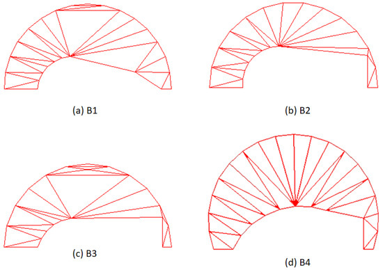
Figure 1.
Designed lenses by modifying inner and outer curvatures and thickness.
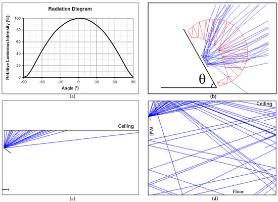
Figure 2.
(a) Beam angle characteristics of the LED; (b) A close look of the setup of the simulation. is the relative angle between the LED and the lens to horizontal axis (c) Setup of the simulation of the luminaire to the ceiling with = 50 and distance d = 40 cm (d) Setup of the simulation of the luminaire to the ceiling and to two reflection surfaces. Sizes of the surfaces imitates the size of a real room: 4 m long, 4 m wide and 3 m high.
2.2. Uplighting Setups For Simulation
To analyze the productivity of the lens contributing to light dispersion, we consider these factors of the simulation: (1) the angle theta that the light source and the lens make with the horizontal axis and (2) the distance of this system from the ceiling. During the simulation, the LED and the foot of the lens are always kept paralleled. There are thirty layout rays shown in the Figure 2 to imitate the light propagation: (b) after transmitting through the lens; (c) how it goes to the ceiling and (d) how the light is reflected from the ceiling and the walls. In the simulation using Zemax software, we trace 10 rays from one LED and collect the illuminance pattern by putting the detector on the ceiling and on the floor. Since the ceiling is the most important secondary lighting surface, we first maximize the result of illuminating the ceiling then adjust it to get the highest productivity on the floor.
2.3. Illuminance Patterns on the Ceiling by Uplighting Method
Figure 3 demonstrates the irradiance illuminance onto the ceiling of one single LED corresponding to each design of the lens. The red part is the most illuminated area and plays the most important role in reflecting light to other surfaces. However, if we enlarge only the red area, a great contrast is likely to happen and lead to low diffusion productivity. Therefore, the green gradient, which is the second illuminated area, should also be considered. The lighting patterns of the LEDs using a freefrom lens will present the broadening of both the main parts; i.e., the red part and the gradient enlightened area.
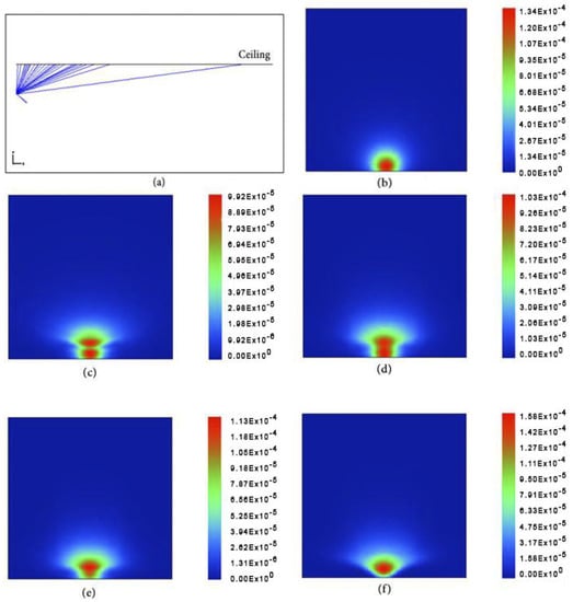
Figure 3.
Light distribution on the ceiling with the set up (a) at distance of d = 40 cm of (b) no lens; (c) B1; (d) B2; (e) B3; (f) B4.
In the no-lens configuration, the light spreads out equally around the center of a round-shaped area and there is a cut on one edge because the luminaire was setup to cling on one wall so part of the light would go to that upper wall instead of going to the ceiling. Compared to no-lens illuminance, the lenses appear to be very effective in enlarging the light distribution. The sketching by the vertical axis of lighting pattern is noticeable and is about 1.5 to twice as far as the no-lens model, especially in lens B1 and lens B2; meanwhile, lens B3 and B4 show superiority in extending the light to the horizontal direction. We can observe a significant change of the gradient; the green part opens up mostly on the top and reaches out further from 30 to 40 percent and more uniform than the original. This outcome is anticipated to bring a positive effect on later simulations.
2.4. Illuminance Patterns on the Floor by Uplighting Method
For the floor model, the light goes directly to the ceiling in an angle = 50 and distance d = 40 cm, to the opposite upper wall and continues to go across the whole room and end up on the detector on the floor. The model of setup is shown in the Figure 4a and the results of light distributions for the cases of no lens, lens B1, B2, B3, B4 are shown in the Figure 4b–f, respectively. Analyzing the outcome on the floor helps find out which lens is most effective in practice. Instead of focusing on one side of the floor, the light now concentrates more in the center and is more equal thanks to the lenses’ light bending. Lens B1, B2 and B3 send 30–40 percent of light to the middle of the room and expand the coverage of light to every side and corner. The observable blue part in no-lens illuminance, which is the less illuminated area, seems to disappear when the lenses are installed. Among these figures. the most remarkable outcome is provided by lens B4 with the highest uniformity all across the floor. For this reason, we choose lens B4 for further study.
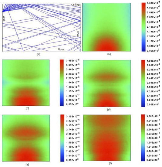
Figure 4.
Light distribution on the floor with the setup (a) at distance of d = 40 cm of (b) no lens; (c) B1; (d) B2; (e) B3; (f) B4.
2.5. Multiparameters Optimization
2.5.1. Optimization of Distance Factor
For an ideal three-meter-high room, we evaluate the result of lighting on the floor with several distances from the luminaire to the ceiling. The simulation results are shown in the Figure 5. The figure demonstrates that the uniformity is proportional to the separation from the ceiling. This outcome is expected since light reaches further onto the ceiling when the distance increases. However, the installation should be less than 0.5 m to the ceiling to fit in indoor architecture and avoid other household implements. The bottom cover blocks direct view to the light source and deletes direct glare.
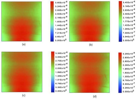
Figure 5.
Light distribution of lens B4 on the floor at distance from the ceiling of (a) 20 cm; (b) 30 cm; (c) 40 cm; (d) 50 cm.
2.5.2. Optimization of Angle Factor
The setup for the simulation of light distritution of lens B4 on the floor is shown in the Figure 6a and the results of light distributions at the angles theta of 45, 50, 55, 60 and 65 are shown in the Figure 6b–f, respectively The angle that the foot of the luminaire makes with the horizontal axis impacts strongly on light dispersion. The larger the angle, the more light is reflected to the upper walls and vice versa. The change in angle affects the angle of incidence to each surface as well as the propagation of light, which results in various patterns of illuminance as shown below. To attain balanced brightness on the floor, the angle theta chosen is between 45 and 65. Any other value out of this range leads to a disproportion in ceiling lighting; thus, high uniformity might hard to be achieved. We notice that the uniformity increases gradually from = 45 to = 60 then drops dramatically when at = 65. Light diffusion on the floor reaches the maximum at = 60.
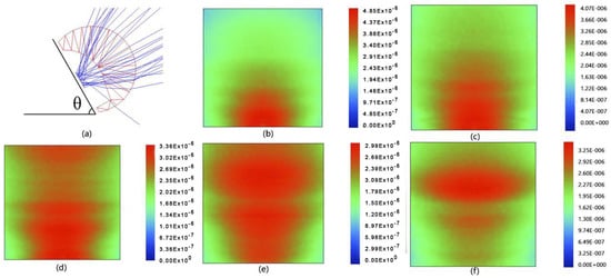
Figure 6.
A close lock of the setup of simulation (a). Light distribution of lens B4 on the floor at the angle of (b) 45; (c) 50; (d) 55; (e) 60; (f) 65, and the distance from ceiling of 40 cm.
3. Conclusions
Aware of the importance of Human Centric Lighting, we propose in this paper designs of freeform lenses to obtain the most luminos uniformity over an indoor space and several configurations of lamps and installations for residential architecture. With the improvement of light uniformity using these fixtures, a better vision is promising, which might result in less chance of myopia and improvement in health and mental wellness. According to a previous study of lens design, distance factor and angle factor, lens B4 at angle 60 and distance 0.5 m to the ceiling for simulation for installation of the luminaire has achieved maximum uniformity within a given space. Since the size of a commercial LED is small, a fixture using light accumulated from many LED sources for a uniform distribution, like a single LEDs array, is preferred to be used in real life. A lamp with the length of 1.2 m consisting of 50 equidistantly aligned LEDs is suggested to maintain a reasonable size for a fixture. By distributing the LEDs over a larger area, we enlarge the reflection surfac and the secondary light source, and the rise of the uniformity on the floor is noticeable. For a common combination, it is recommended to set up two lamps of this kind on two opposite walls of one room. This symmetrical installation clears out the dark areas in the corners and ensures the uniformity in the center of the room. For an alternative system, four to six of these lamps can make up a square or hexagonal ceiling lamp. Instead of directly downlighting, like conventional ceiling lamps, this fixture lights up the ceiling and makes use of reflection by the ceiling and wall to illuminate the whole space. This overcomes the disadvantages of imbalanced illumination and glares and costs less than a general fixture with the equivalent quality of illumination and provides promising sustainability.
Author Contributions
Q.C.T., T.Q.T. and P.H.D. proposed the idea and designed the simulation. D.T.G. and T.L.L. performed simulations and analyzed the data. All authors have read and agreed to the published version of the manuscript.
Funding
This research is supported by a public grant of Ministry of Science and Technology of Vietnam under the project ĐTĐLCN.30/18.
Conflicts of Interest
The authors declare no conflict of interest
References
- Babadi, S.; Ramirez-Iniguez, R.; Boutaleb, T.; Mallick, T. Analysis of uniformity of illumination of a freeform lens when combined with different optical sources. Proc. SPIE 2016, 9744, 974417. [Google Scholar] [CrossRef]
- Evans, D.; Abrahamse, H. Phototherapy—A treatment modality for wound healing and pain relief. Afr. J. Biomed. Res. 2007, 10, 2. [Google Scholar]
- Boyce, P. Editorial: Exploring human-centric lighting. Light. Res. Technol. 2016, 48, 101. [Google Scholar] [CrossRef]
- Figueiro, M.G. An Overview of the Effects of Light on Human Circadian Rhythms: Implications for New Light Sources and Lighting Systems Design. J. Light Vis. Environ. 2013, 37, 51–61. [Google Scholar] [CrossRef]
- Zielinska-Dabkowska, K.M. Make lighting healthier. Nature 2018, 553, 274–276. [Google Scholar] [CrossRef]
- Rea, M.; Figueiro, M.; Bullough, J. Circadian photobiology: An emerging framework for lighting practice and research. Light. Res. Technol. 2002, 34, 177–187. [Google Scholar] [CrossRef]
- Bodrogi, P.; Vinh, Q.T.; Khanh, T.Q. Opinion: The usefulness of light sources in human centric lighting. Light. Res. Technol. 2017, 49, 292. [Google Scholar] [CrossRef][Green Version]
- Jiang, J.; To, S.; Lee, W.B.; Cheung, B. Optical design of a freeform TIR lens for LED streetlight. Optik-Int. J. Light Electron Opt. 2010, 121, 1761–1765. [Google Scholar] [CrossRef]
- Grondzik, W.T.; Kwok, A.G. Mechanical and Electrical Equipment for Buildings-12E; John Wiley & Sons, Inc.: Hoboken, NJ, USA, 2014; pp. 683–719. [Google Scholar]
- Kassay, C.E.; Pane, S.M.; Kassay, M.A.; Kassay, J.P. Fluorescent Lighting Fixtures With Controlled Uplight Capability. U.S. Patent No. 7,070,303, 4 July 2006. [Google Scholar]
- Dahlen, K.; Stolte, B. Luminaire with Uplighting and Downlighting Capabilities. U.S. Patent No. 10,451,249, 22 October 2019. [Google Scholar]
- Fang, F.; Cheng, Y.; Zhang, X. Design of freeform optics. Adv. Opt. Technol. 2013, 2, 445–453. [Google Scholar] [CrossRef]
- Coluccelli, N. Nonsequential modeling of laser diode stacks using Zemax: Simulation, optimization, and experimental validation. Appl. Opt. 2010, 49, 4237–4245. [Google Scholar] [CrossRef]
- Ding, Y.; Liu, X.; Zheng, Z.R.; Gu, P.F. Freeform LED lens for uniform illumination. Opt. Express 2008, 16, 12958–12966. [Google Scholar] [CrossRef] [PubMed]
- Essameldin, M.; Fleischmann, F.; Henning, T.; Lang, W. Design and evaluation of a freeform lens by using a method of luminous intensity mapping and a differential equation. Proc. SPIE 2017, 10110, 1011006-1. [Google Scholar] [CrossRef]
- Zheng, Z.; Xiang, H.; Xu, L. Freeform surface lens for LED uniform illumination. Appl. Opt. 2009, 48, 6627–6634. [Google Scholar] [CrossRef] [PubMed]
- Ries, H.; Muschaweck, J. Tailored freeform optical surfaces. J. Opt. Soc. Am. A 2002, 19, 590–595. [Google Scholar] [CrossRef]
- Ma, D.; Feng, Z.; Liang, R. Freeform illumination lens design using composite ray mapping. Appl. Opt. 2015, 54, 498–503. [Google Scholar] [CrossRef]
- Luo, Y.; Feng, Z.; Han, Y.; Li, H. Design of compact and smooth free-form optical system with uniform illuminance for LED source. Opt. Express 2010, 18, 9055–9063. [Google Scholar] [CrossRef]
- Chin, T.Y.; Saif, A.E.A.; Poopalan, P. Apparent Uniform of Light Emission from Multiple Spot Sources. In Proceedings of the 2013 IEEE 4th International Conference on Photonics (ICP), Melaka, Malaysia, 28–30 October 2013; pp. 297–299. [Google Scholar]
- Lai, M.F.; Chen, Y.C.; Anh, N.D.Q.; Chen, T.Y.; Ma, H.Y.; Lee, H.Y. Design of asymmetric freeform lens for low glared LED street light with total internal reflection. Opt. Express 2016, 24, 1409–1415. [Google Scholar] [CrossRef]
- Lee, X.-H.; Moreno, I.; Sun, C. High-performance LED street lighting using microlens arrays. Opt. Express 2013, 21, 10612–10621. [Google Scholar] [CrossRef]
- Lee, H.E.; Lee, S.H.; Jeong, M.; Shin, J.H.; Ahn, Y.; Kim, D.; Oh, S.H.; Yun, S.H.; Lee, K.J. A photostimulation using monolithic flexible vertical AlGaInP light-emitting diodes. ACS Nano 2018, 12, 9587–9595. [Google Scholar] [CrossRef]
- Lee, H.E.; Choi, J.; Lee, S.H.; Jeong, M.; Shin, J.H.; Joe, D.J.; Kim, D.; Kim, C.W.; Park, J.H.; Lee, J.H.; et al. Monolithic Flexible Vertical GaN Light-Emitting Diodes for a Transparent Wireless Brain Optical Stimulator. Adv. Mater. 2018, 30, 1800649. [Google Scholar] [CrossRef]
- Gissibl, T.; Thiele, S.; Herkommer, A.; Giessen, H. Sub-micrometre accurate free-form optics by three-dimensional printing on single-mode fibres. Nat. Commun. 2016, 7, 11763. [Google Scholar] [CrossRef] [PubMed]
© 2020 by the authors. Licensee MDPI, Basel, Switzerland. This article is an open access article distributed under the terms and conditions of the Creative Commons Attribution (CC BY) license (http://creativecommons.org/licenses/by/4.0/).