Article

Push-Out Testing of Demountable Bolted Shear Connection in Composite Cold-Formed Steel Beams: Experimental Evaluation and Analysis

1
Stabilnost Ltd., 21000 Split, Croatia
2
Faculty of Civil Engineering, University of Zagreb, 10000 Zagreb, Croatia
*
Author to whom correspondence should be addressed.
Buildings 2026, 16(5), 979; https://doi.org/10.3390/buildings16050979
Submission received: 20 December 2025 / Revised: 12 February 2026 / Accepted: 27 February 2026 / Published: 2 March 2026

Abstract

The Innovative Lightweight Cold-Formed Steel–Concrete Composite Floor System (LWT-FLOOR) addresses key challenges faced by the construction industry related to the efficiency, adaptability, and life-cycle usability of structural elements. Within this context, the present study investigated the behaviour of demountable bolted shear connections in a composite system combining built-up cold-formed steel (CFS) girders and concrete slabs. An experimental programme comprising 18 push-out tests was conducted on two composite configurations: built-up back-to-back CFS sections and built-up sections incorporating a corrugated web. The influence of key parameters, including the bolt diameter, CFS thickness, steel grade, and connector spacing, was evaluated. The results show that increasing the bolt diameter enhanced the shear resistance and initial stiffness while reducing ductility, whereas reducing the CFS thickness led to a moderate decrease in resistance accompanied by a pronounced increase in ductility. The incorporation of a corrugated web increased the ultimate shear resistance by approximately 30–40%. The existing analytical models from current standards were found to be inadequate; however, the introduction of a spacing-dependent correction factor into the prEN 1994-1-1 model significantly improved the prediction accuracy, reducing the coefficient of variation from 16% to 4.36%. The findings provide a quantitative basis for improving the design of demountable shear connections in lightweight composite CFS-concrete systems.

1. Introduction

The use of sustainable and environmentally friendly materials in the construction industry has gained considerable attention in recent years due to the growing awareness of the environmental impact of traditional building practices. This demand has led to the continuous pursuit of innovative structural systems, surpassing the possibilities of traditional solutions [1]. Consequently, in recent years, the use of composite systems in construction has experienced an increasing trend driven by their structural efficiency and economic viability due to the combination of the favourable properties of the two materials. These advantages in the field of steel-concrete composite floor systems can be further enhanced by integrating CFS sections into steel-concrete composite systems [2,3]. The application of the CFS section in composite steel-concrete systems offers several advantages, such as a high strength-to-weight ratio, ease of fabrication, ease of transportation, and rapid installation [4]. It is well known that one of the biggest challenges associated with CFS sections is their relatively low thickness, which makes them particularly susceptible to various forms of instability. An effective way to overcome this problem is to develop a composite action between the CFS section and concrete slab. This composite interaction ensures that the CFS section primarily resists tensile forces while the concrete slab takes on compressive stresses. Such stress distribution significantly reduces or even eliminates the compressive stresses in the CFS, reducing the probability of local or global buckling.
However, to enable a reliable composite action between a built-up CFS section and the concrete slab, a key requirement is the application of an effective shear connection. This presents another challenge, as conventional welded headed studs are unsuitable for use with thin-walled CFS sections. The welding process leads to residual stresses and geometric imperfections, which are especially unfavourable for thin steel elements, making this method unsuitable from both structural and sustainability points of view. To address this, bolted shear connectors have emerged as an effective and sustainable alternative. Not only do they ensure reliable force transmission between the CFS and the concrete slab, but they also offer the advantage of being demountable. This facilitates the easier disassembly and reusability of structural elements, which aligns with the growing demand for sustainable construction.
To further emphasise the aforementioned advantages and enhance the stability of CFS sections, the use of built-up CFS girders with various cross-sectional configurations is becoming increasingly frequent in this area of research. These girders are formed by mechanically joining multiple CFS sections into a single composite cross-section using bolts, spot welds or other fastening methods. The result is a structurally efficient member that offers a comparable or even better mechanical performance than that of conventional hot-rolled steel sections while also benefiting from a significantly reduced self-weight. In addition, introducing corrugated webs into built-up CFS girders has been shown to improve their stability further [5]. Corrugated webs increase the local buckling stability and allow for a more flexible and efficient arrangement of shear connectors.
In conventional steel-concrete composite beams with hot-rolled steel sections, the failure of bolted shear connectors usually occurs in two distinct failure mechanisms: shear failure or yielding of the shear connector and associated concrete failure, such as crushing or pry-out. The steel section, due to its considerable thickness and stiffness, generally behaves rigidly at the connection interface and thus does not significantly influence the performance of the connector. However, in systems with thin-walled CFS sections (typically 1–3 mm thick), the interaction between the CFS section and the shear connector becomes significantly more complex. The reduced thickness and inherent slenderness of the CFS elements lead to an increased susceptibility to local buckling, elongation of the bolt holes and deformation around the bolt holes. As a result, the load transfer mechanism is not only subject to the interaction between the bolt and the concrete but is also strongly influenced by local instabilities of the thin CFS section. This leads to an additional failure mode, such as bearing deformation, tearing, crippling or distortional buckling around the bolt holes. These additional deformations and failure modes are rarely observed in conventional systems and pose a major challenge for both design and analysis. While such behaviour has been partially investigated in studies using push-out tests, they often neglect the effects of built-up CFS cross-sections, which introduce further complexity due to the presence of multiple elements. Therefore, a limited understanding of how shear connections behave remains, especially when it comes to complex built-up cross-sections of composite systems. Furthermore, the existing standards and models for shear connections derived from conventional systems neglect these interaction effects, leading to non-conservative or overly conservative predictions of shear resistance and ductility.
Therefore, there is a clear need to investigate the specific failure mechanisms and load transfer behaviour of shear connectors in composite systems incorporating built-up thin CFS sections. These knowledge gaps are particularly critical in the context of innovative systems such as those proposed in the LWT-FLOOR project [6], which combine a built-up CFS girder with corrugated webs and demountable bolted shear connectors embedded in composite concrete slabs. While these systems are promising from a sustainability and weight reduction perspective, they require a much better understanding of how the composite action is achieved and how local instabilities of the CFS elements interact with the behaviour of the shear connectors. This includes identifying the failure mechanisms, quantifying the effects of the connector geometry and material properties, and comparing the observed behaviour against current design standards. Without this knowledge, reliable design and practical application are only possible to a limited extent.
Additionally, although the primary load transfer between the CFS section and the concrete slab occurs through the flanges and the bolted shear connectors, the configuration of the CFS profiles can also significantly influence the performance of the shear connection. In particular, the insertion of a corrugated web between the CFS profiles increases the transverse spacing between the connectors and alters the overall stiffness and stability of the built-up section. This configuration promotes a more favourable stress distribution in the surrounding concrete and reduces the interaction between concrete failure zones around the connectors. It also enhances the lateral stability of the flanges, potentially influencing local deformation patterns and slip behaviour. In this study, these geometric and mechanical differences justified the inclusion of both configurations, with the corrugated web inserted between the profiles and without it. Comparing these two behaviours enables the evaluation of how the built-up CFS girder configuration affects the shear connector performance.
In line with the increasing application of CFS elements within the construction industry, there has been a surge in research interest in understanding the behaviour of shear connections in CFS-concrete composite systems. Hosseinpour [7] conducted experimental push-out tests to investigate the response of bolted shear connectors with a single embedded nut in CFS composite and concrete beams. The investigation focused on three main variables: the bolt diameter, bolt thickness and thickness of the CFS sections. Minor bearing damage and distortional buckling of the flanges were observed in specimens with 1 mm thick CFS. By increasing the thickness to 2 mm, the failure pattern changed so that the bolts yielded, and occasional cracks appeared in the concrete, along with slight bearing damage in the CFS section. Most of the specimens showed ductile behaviour. The research was further developed using finite element modelling [8] to estimate the ultimate shear capacity, ductility and failure mechanisms. Five additional variables were included in this extended analysis: the CFS thickness and strength of the CFS, the compressive strength of the concrete, the bolt diameter and the height of the embedded bolt. The parametric study revealed the complex nature of the connection behaviour. For thinner CFS sections, the resistance was mainly influenced by the thickness and strength of the CFS profile, while for thicker sections, the screw diameter and concrete properties played a greater role. Further confirmation of the complex behaviour of shear connections in CFS composite beams was found in a separate study [9], in which the results of a validated finite element analysis were compared with design predictions from standards. The lack of correlation between the FEM results of the shear resistance per bolted shear connector and the design predictions indicated the unreliability of such expressions for determining the shear resistance in these systems. In addition, the behaviour of shear connections in CFS-concrete composite systems was investigated in two studies.
Lawan et al. [10] improved the understanding of bolted shear connections by conducting experimental tests on both push-out specimens and full-scale composite beams. Their findings showed that the bolted shear connection significantly improved both the ultimate load and moment capacity, offering notable resistance and ductility. Furthermore, the experimental data closely matched the theoretical models, with low standard deviations, indicating reliable analytical predictions. Additionally, the study found that increasing the spacing between the connectors improved the system capacity without compromising the composite action or causing major deformations. Further research by Lawan et al. [11,12] investigated the shear connector’s performance when composite beams consist of self-compacting concrete (SCC) and CFS, aiming to ensure effective bonding. Push-out tests with M14 and M16 bolts showed failure through the concrete crushing and buckling of the CFS flanges and webs. Varying the longitudinal spacing of the connectors revealed that greater spacing increased the shear resistance. Overall, the proposed connector demonstrated a strong structural performance and high resistance capacity.
Another contribution to a better understanding of the behaviour of the bolted shear connection is the study by Ataei et al. [13], which included 15 push-out tests on bolted shear connections in composite CFS-concrete beams with solid concrete slabs. The study focused on the effects of the CFS thickness, bolt diameter and bolt strength on the performance of the shear connection. The findings revealed that the bolt grade had little effect on the shear resistance, while larger bolt diameters and thicker CFS sections significantly increased the shear capacity. Thicker CFS sections also shifted the failure mechanism from buckling to shear connector fracture, though this reduced ductility. The study emphasises that current design standards often underestimate the shear load capacity, highlighting the need for a more reliable analytical method.
Additionally, a parametric numerical analysis [14] expanded the database and investigated failure mechanisms, resistance and ductility in greater depth. The analysis considered factors such as the bolt strength, the thickness of the CFS section, the concrete strength and the pretension force of the bolt. The results indicated that the bolt size, pretension, and concrete strength had minimal effects on the shear load capacity and ductility in the analysed configurations. Salah et al. [15] conducted an experimental study to evaluate the effects of changing the bolt diameter and cross-section of the CFS beam on the behaviour of the shear connection. The study concluded that the cross-section of the CFS beam does not affect the failure mode if the bolt diameter remains the same. However, specimens with an I-shaped cross-section of the CFS beam showed slightly better load-bearing capacity values, while box cross-sections increased the stiffness of the shear connection compared to I-shaped sections.
While previous studies primarily focused on bolted shear connections with a single embedded nut in solid slabs, Karimipanah et al. [16] expanded the research to CFS composite beams with profiled steel sheeting. The authors introduced a 3D finite element model to analyse the performance of bolted shear connections in these beams. They investigated factors such as the concrete strength, slab thickness, strength and height of the CFS section, profiled sheeting thickness, and shear connector properties. The study found that increasing the concrete strength and profiled steel sheet thickness improved the ultimate load capacity, but the excessive concrete strength had minimal effect. Profiled sheeting improved the bending capacity by 15%, while its thickness had only a minimal influence. Higher strength of the CFS section and increased strength and beam height improved resistance and stiffness.
Additionally, optimising the degree of shear connection in critical areas significantly increased the stiffness and load capacity. Smaller, more numerous bolts were also more suitable than using fewer larger bolts. Furthermore, Rahnavard et al. [17] contributed to understanding bolted shear connections in profiled concrete slabs of composite CFS-concrete beams. Their study combined experimental testing and numerical modelling to evaluate the performances of built-up CFS-lightweight concrete (LWC) beams in two configurations. Tests on four full-scale specimens showed that increasing the number of bolted connectors improved the flexural capacity and shifted the neutral axis upward, resulting in better stress distribution. Failures such as local buckling, flange curling, and web crippling were observed, with web crippling being more pronounced at lower shear connection levels. Finite element analysis accurately captured the behaviour and failure modes. However, the existing design methods were found to overestimate the flexural capacity, leading the authors to propose changes to better address their behaviour.
Friction grip bolts, as another type of bolted shear connection in composite structures, were investigated in a separate study by Shakarami et al. [18] using validated finite element analyses. Based on the comprehensive parametric analysis results, the authors provided a design recommendation for estimating the ultimate shear capacity of this type of connection. In addition, Dias et al. [19] investigated the behaviour of a novel shear connector in CFS-concrete composite beams, in which a bolt is fixed to the steel section with an internally threaded flat rivet. The results showed sufficient strength and ductility for this type of composite beam.
In addition to bolted shear connections, various innovative shear connections have been developed in which steel elements are embedded into the concrete slab [20,21,22,23,24,25,26]. Some of these connections are demountable, as shown in a dedicated study [20], and they generally exhibit admirable shear resistance and ductile behaviour compared to conventional solutions.
A literature review indicates that, despite ongoing research, there is still a limited understanding of the behaviour of bolted shear connections in composite CFS-concrete beams. As a result, there is currently no reliable analytical method to accurately predict the shear resistance of these connections in relation to the expected failure mechanisms. Previous studies have emphasised the complex nature of bolted shear connections mainly due to using the relatively thin CFS cross-section. In particular, factors such as the thickness of the CFS section, bolt geometry and concrete strength have been identified as key elements influencing the resistance, ductility and failure modes of these connections. A significant gap in the current literature lies in the limited research on bolted shear connections within composite beams incorporating built-up CFS sections. These configurations offer promising advantages over conventional composite systems, offering a comparable or even improved structural performance while substantially reducing the overall weight of the structure. The existing studies dealing with this topic predominantly focus on CFS sections with thicknesses up to 2 mm, which are usually either unconnected or joined using small-diameter bolts. Using such thin-walled elements leads to complex behaviour in the shear connection, with the predominant failure mode being the bearing failure of the bolt hole, often accompanied by the local instability of the slender steel components. This type of failure is generally undesirable, as it prevents the activation of more favourable failure modes, such as concrete pry-out failure or bolt shear failure. These limitations underscore the need for further experimental research to improve the understanding of bolted shear connections in such systems and to support the development of reliable design models for predicting their resistance.
Therefore, the main objective of this study was to improve the understanding of bolted shear connections in composite CFS–concrete beams through comprehensive experimental testing. An extensive experimental programme was conducted to achieve this, including tests on base materials and 18 push-out specimens. The research focused on two different configurations of composite CFS–concrete specimens. The first configuration, referred to as the BB series, consists of back-to-back CFS sections with demountable bolted shear connections (M12 and M16) embedded in a reinforced-concrete slab with an open-trough profiled steel sheeting. The second configuration, referred to as the BCWB series, incorporates a built-in corrugated web between the back-to-back CFS profiles. The experimental results were thoroughly analysed to identify the failure modes and to evaluate the initial stiffness, ultimate resistance and ductility of the specimens. By comparing the performances of the two configurations in terms of these key parameters, this study sets itself apart from the existing research by demonstrating the potential for improved shear connection behaviour through the application of built-up CFS sections. These findings suggest that various forms of built-up CFS sections may offer performance characteristics comparable to those of conventional composite beams while providing significant weight reduction. Finally, the experimental results were compared with analytical predictions derived from several current design standards [27,28,29,30,31] to assess their applicability.

2. Experimental Programme

2.1. Experimental Strategy and Details of Test Specimens

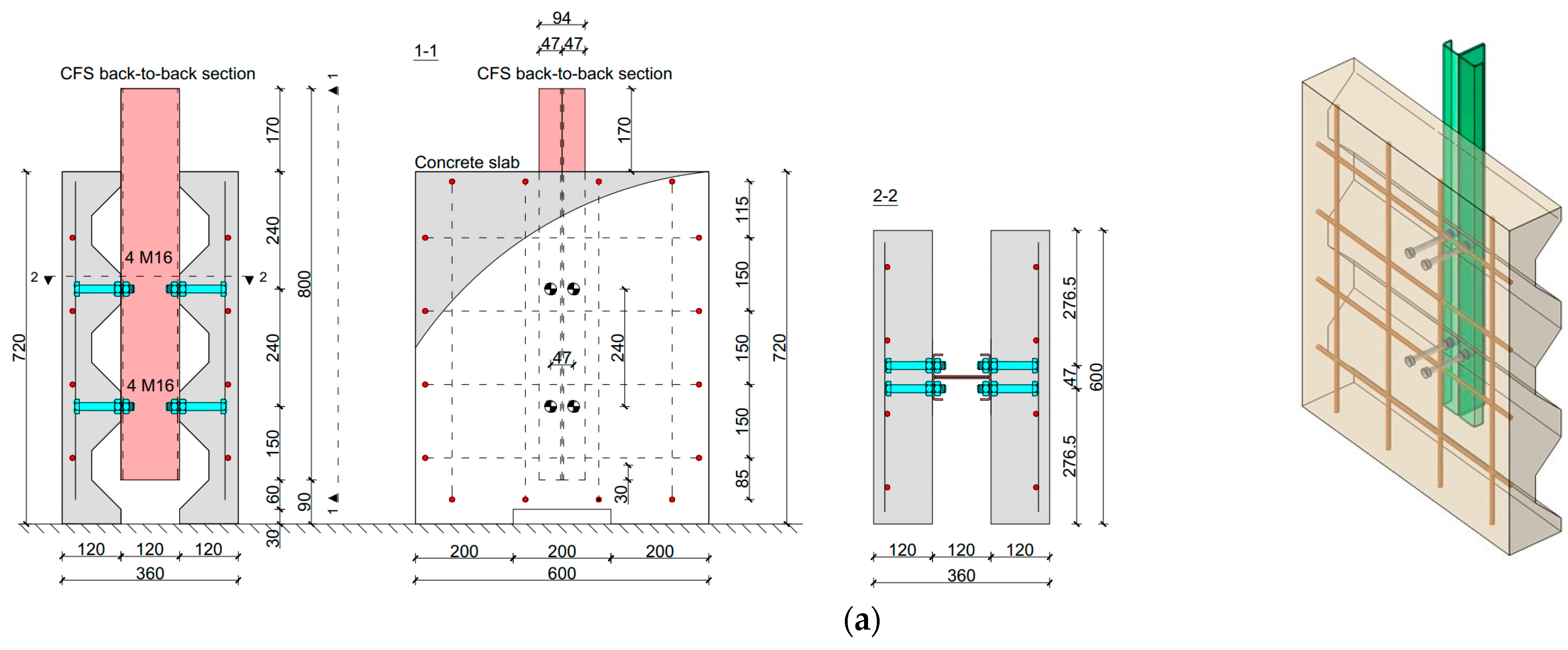
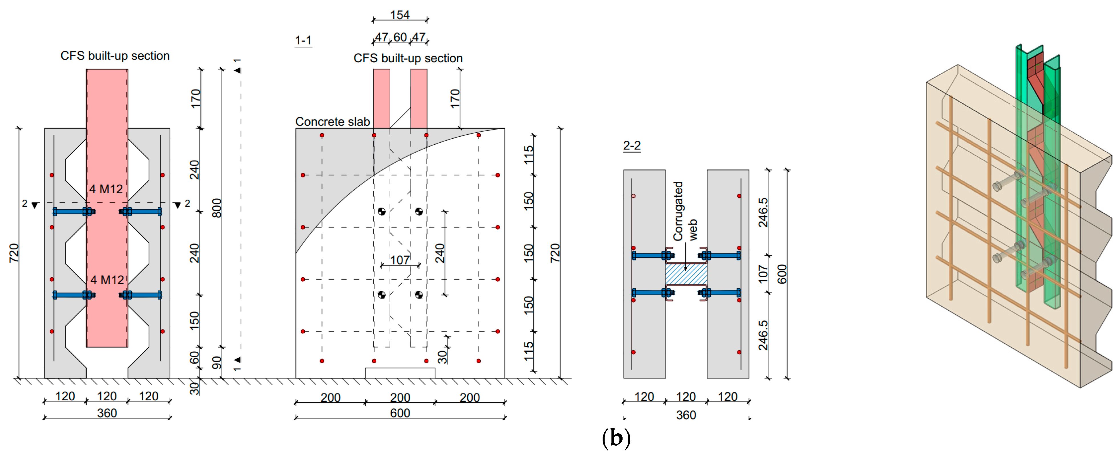
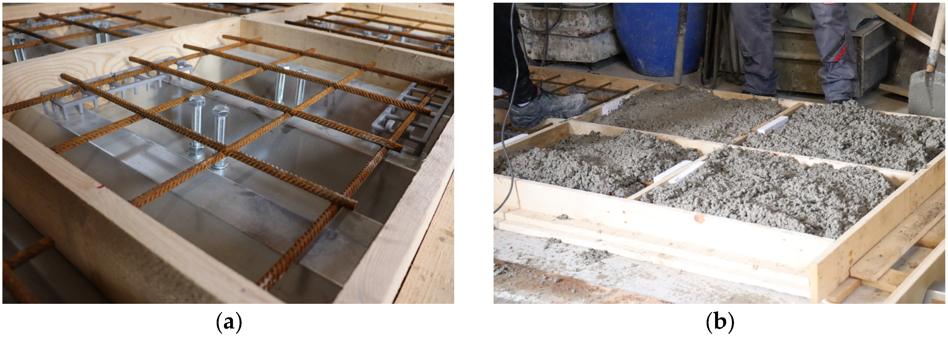
This study contains a detailed description of the experimental research with a total of 18 push-out specimens. The experimental research was carried out as part of the LWT-FLOOR project at the Structural Testing Laboratory of the Faculty of Civil Engineering in Zagreb. The main objective was to investigate the behaviour of the shear connection in two different composite CFS concrete systems. The push-out specimens were divided into two series. The BB series comprises six specimens of back-to-back CFS sections with a demountable bolted shear connection (M12 and M16) embedded in a reinforced-concrete slab with an open-trough profiled steel sheeting, as shown in Figure 1a. The BCWB series consists of twelve test specimens made of CFS sections with a corrugated web with a demountable bolted shear connection (M12 and M16) embedded into a reinforced-concrete slab with an open-trough profiled steel sheeting, as shown in Figure 1b.
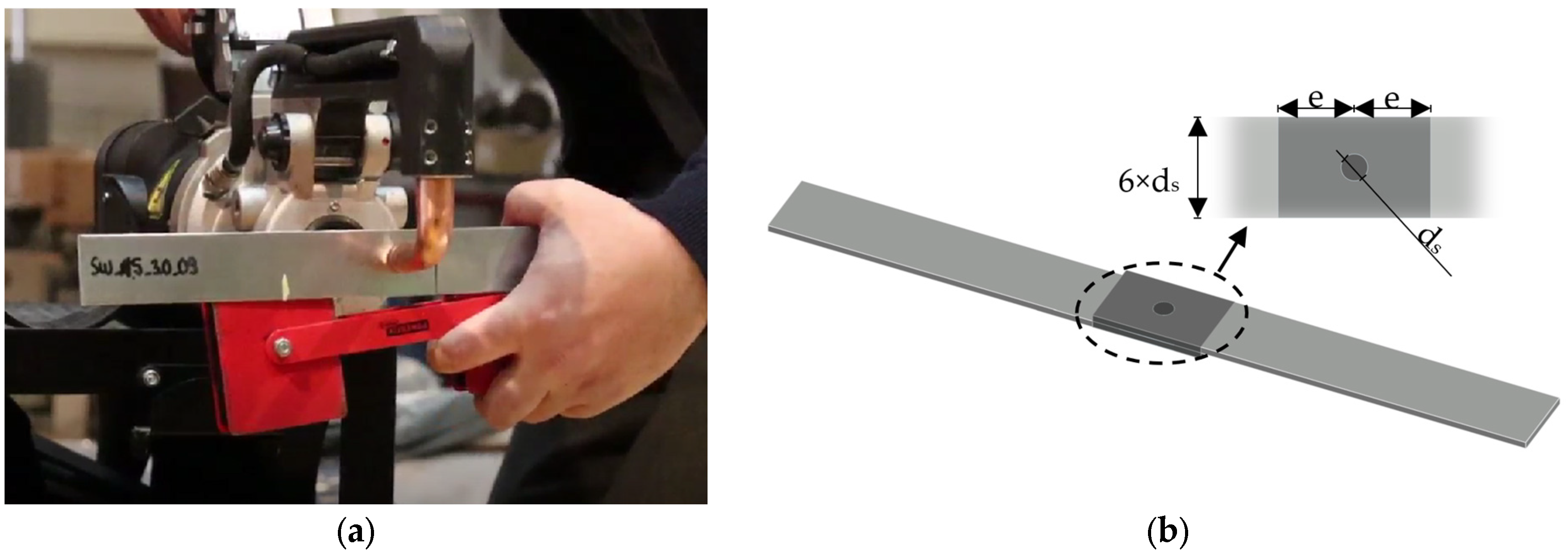
The built-up CFS sections used for the specimens consist of several CFS elements joined together by spot welding, as has already been previously described [6]. A back-to-back assembly method was used for the BB series, configuring the steel section from two C profiles facing each other with webs. Spot welds at discrete points along the web section make the connection between the CFS C profiles. In the BCWB series, the built-up formation process is similar to that of the BB series, whereby an additional CFS element, namely, a corrugated web, is installed. This corrugated web is positioned between the CFS C profiles, and the connections are secured using spot-welding technology. Each test specimen consists of two concrete slabs measuring 720 × 600 × 120 mm and Q524 reinforcement mesh (steel grade: B500B), which is positioned centrally within the concrete thickness above the profile rib, as shown in Figure 2. In addition, each concrete slab contains four embedded single-nut bolted shear connections, with the height of the embedment in the slabs being 95 mm. The concrete slabs were cast horizontally, and the curing process lasted 28 days. Parallel to the curing process of the concrete slabs, the steel part of the push-out specimens was produced in two stages. In the first stage, the process involved forming the built-up CFS sections using spot-welding technology, as shown in Figure 3. Following the CFS section construction, holes for the bolts were drilled into the flanges of the CFS sections. Finally, the prefabricated concrete slabs and the pre-drilled CFS sections were assembled using a torque wrench to tighten the nuts.
Table 1 gives an overview of the individual specimens, as well as the parameters that were varied within those specimens.

2.2. Material Properties

The material properties of all components used in the push-out specimens were determined using standardised test procedures for each material [32,33]. These experimental investigations were conducted using the Zwick/Roell Z600E static testing machine in the Structural Testing Laboratory at the Faculty of Civil Engineering in Zagreb. The properties of the CFS components and the bolts were determined through comprehensive tensile tests, which provided detailed insights into the yield strength, ultimate strength, and modulus of elasticity of the steel. Shear tests were carried out to assess the resistance of the spot weld between the CFS sections. Furthermore, the concrete cylinders were subjected to a compression test to determine the compressive strength and modulus of elasticity of the concrete. It is important to emphasise that each evaluation strictly adhered to established standard procedures to ensure the credibility and comparability of the obtained results.
The results derived from the experimental test of the material properties were subjected to a statistical evaluation following the guidelines in Annex D of EN-1990 [34]. By using the log-normal distribution, the characteristic value (Xk) of the specific material property was determined according to Equation (1):
X k = exp m y k n s y ,
where my and sy represent the mean and standard deviation, respectively. The factor kn, as given in Table D.1 [34], is applied for 5% characteristic value. In addition, the value of the factor kn is determined as a function of the number of tested specimens and, in this case, without prior knowledge of the coefficient of variation (“Vx unknown”).

2.2.1. Steel

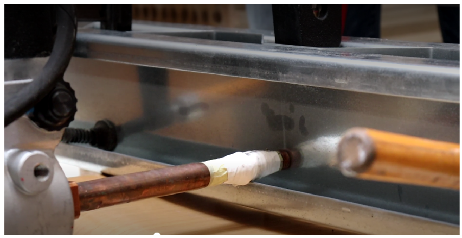
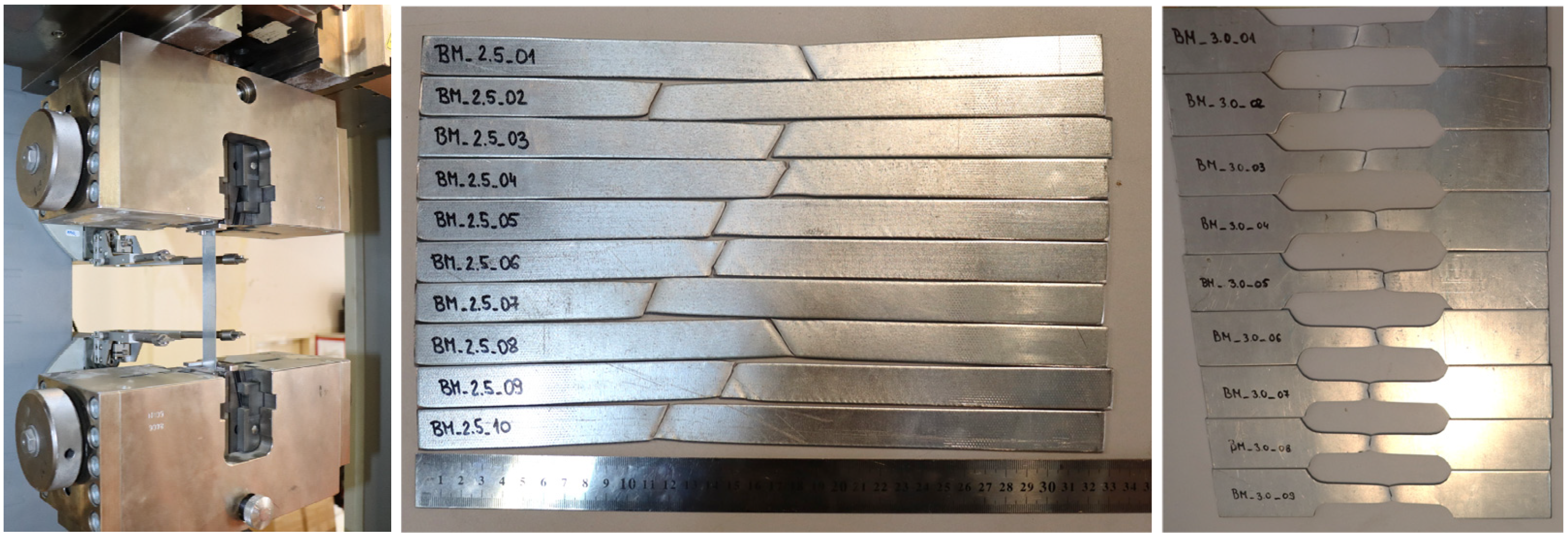
Tensile tests were carried out on coupons to determine the mechanical properties of the CFS components used in the push-out specimens. Following the guidelines of EN ISO 6892-1:2019 [35], flat tensile coupons were prepared for sheets with thicknesses of 1.0, 1.5 and 2.5 mm, while sheets with a thickness of 3 mm were shaped into dog-bone specimens, as shown in Figure 4. The specimens were made from two different steel grades, namely, DX51 Z275 and S350GD. The tensile coupons were cut from CFS sheet rolls, including the flanges and ribs of the CFS beam, all from the same manufacturer. The tensile coupon tests were performed on seven or more specimens of each thickness, resulting in a total of 87 flat CFS tensile coupons being tested.
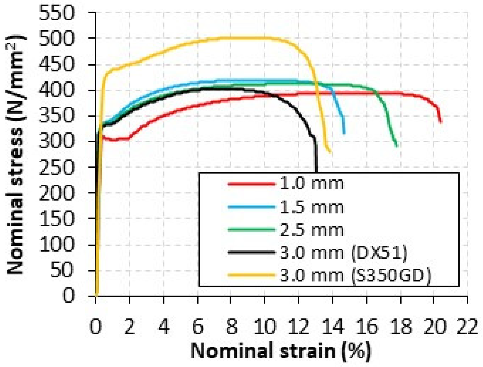
The tensile tests were performed according to the protocol described in EN ISO 6892-1:2019 [35]. During the testing of each coupon, the elongation of the specimen was closely monitored using a digital extensometer, as shown in Figure 4. The results of the tensile tests are shown graphically in Figure 5 in the form of nominal stress–strain curves for each thickness and steel grade of the tested specimens. In addition, the most important mechanical properties of the tested coupons are summarised in Table 2 and Table 3.
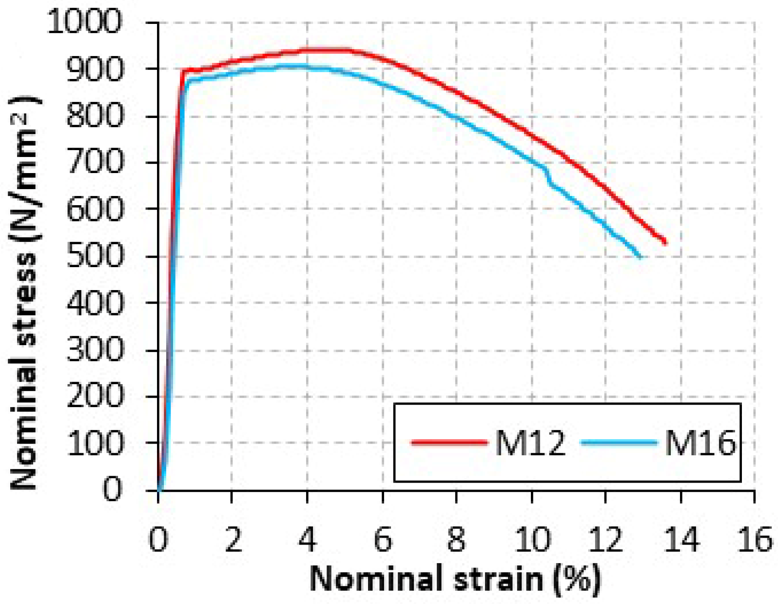
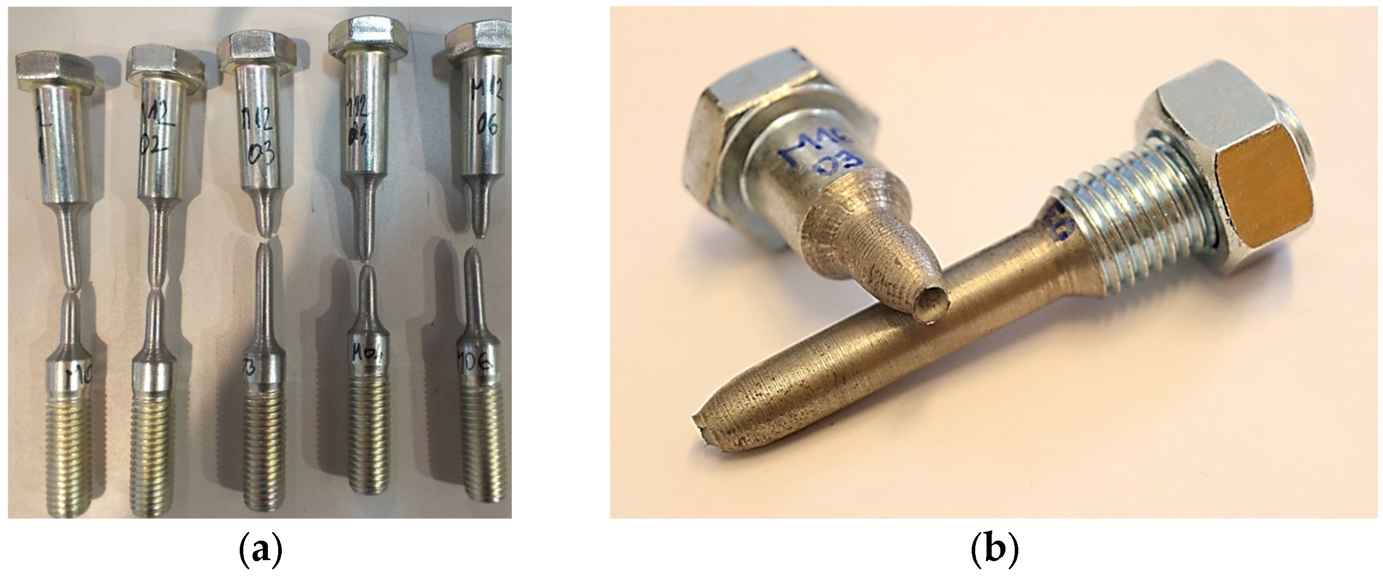
Furthermore, it was also necessary to produce test coupons to determine the mechanical properties of the M12 and M16 bolt materials. A total of 10 round bolt coupons were tested, five of which had a diameter of 5 mm for M12 bolts and five with a diameter of 10 mm for M16 bolts, as shown in Figure 6. The entire procedure complies with the guidelines of EN ISO 6892-1:2019 [35]. The results of the tensile tests are plotted using nominal stress–strain curves, as shown in Figure 7. A detailed summary of the key parameters can be found in Table 4.

2.2.2. Concrete

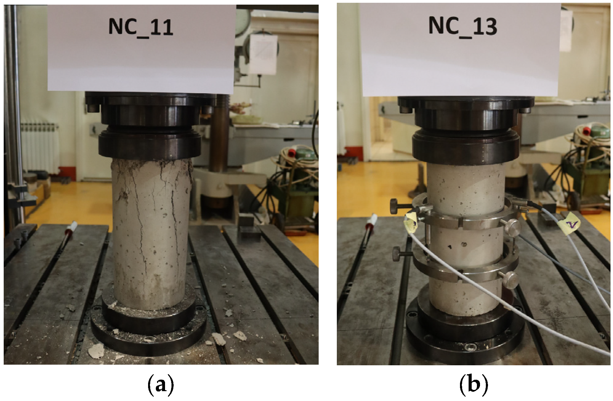
Fifteen concrete cylinders measuring ∅150 × 300 mm were cast simultaneously as the concrete slabs intended for the push-out samples. Once the concrete casting was complete, all cylinders were cured under the same conditions as the concrete slabs for 28 days before being tested. Standardised tests were then carried out to determine the material properties of the concrete slabs. The focus was on determining the concrete compressive strength (fcm,cyl) according to EN 12390-3:2019 [36] and the modulus of elasticity (Ecm) according to EN 12390-13:2021 [37], as shown in Figure 8. The compressive strengths of all cylinders were determined through compression crushing. At the same time, a subset of the specimens was used to test the modulus of elasticity. A set of three LVDT sensors was used to measure displacements between the two rings fixed to the specimens to capture their strain during the tests. The testing of the cylinders took place at the same time as the testing of the push-out specimens to ensure that the most accurate values for the compressive strength of the concrete cylinders could be determined during this period. A detailed summary of the key parameters can be found in Table 5.

2.2.3. Spot Welds

Although spot welds are not directly involved in the transmission of shear forces between steel and concrete interaction, their usefulness as an indicator of the simple and automated processes involved in the construction of built-up girders is noteworthy. The enviable resistance of spot welds also highlights the production’s simplicity and automation. The geometry of the spot weld specimens complies with the guidelines of EN 1993-1-3 [38], and the specimens were welded using a Tecna 3646 HSS spot-welding machine, as shown in Figure 9. The welding parameters (including the welding current, electrode force, welding time, and heat input) were selected in accordance with the manufacturer’s guidelines for the spot-welding equipment, based on the thickness and type of the welded steel sheets. This ensured stable weld quality, consistent failure mechanisms, and the reliable performance of the built-up CFS sections, without introducing additional variables that could not have influenced the push-out test results anyway. Although a total of 273 spot weld specimens were tested, the following section describes the shear test results for three spot weld combinations of CFS sections (1.5–2.5 mm, 1.5–3.0 mm, and 3.0–3.0 mm) used in the push-out specimens. The shear test was performed with a static testing machine, while the elongation was monitored using extensometers. Table 6 provides a comprehensive summary of the results, highlighting the most important parameters of spot welds, such as the ultimate force and the slip at the ultimate force. The analysis of the spot weld specimens revealed two main failure modes: interfacial fracture and full button. Interface fracture occurred in specimens where both sheets were ≥2.5 mm thick, leading to more brittle behaviour. Tear-out of the full button, which occurred more frequently and was observed when at least one sheet was <2.5 mm thick, resulted in higher ductility, as the failure occurred in the base metal while the weld remained intact.

2.3. Test Setup and Loading Procedure for Push-Out Specimens

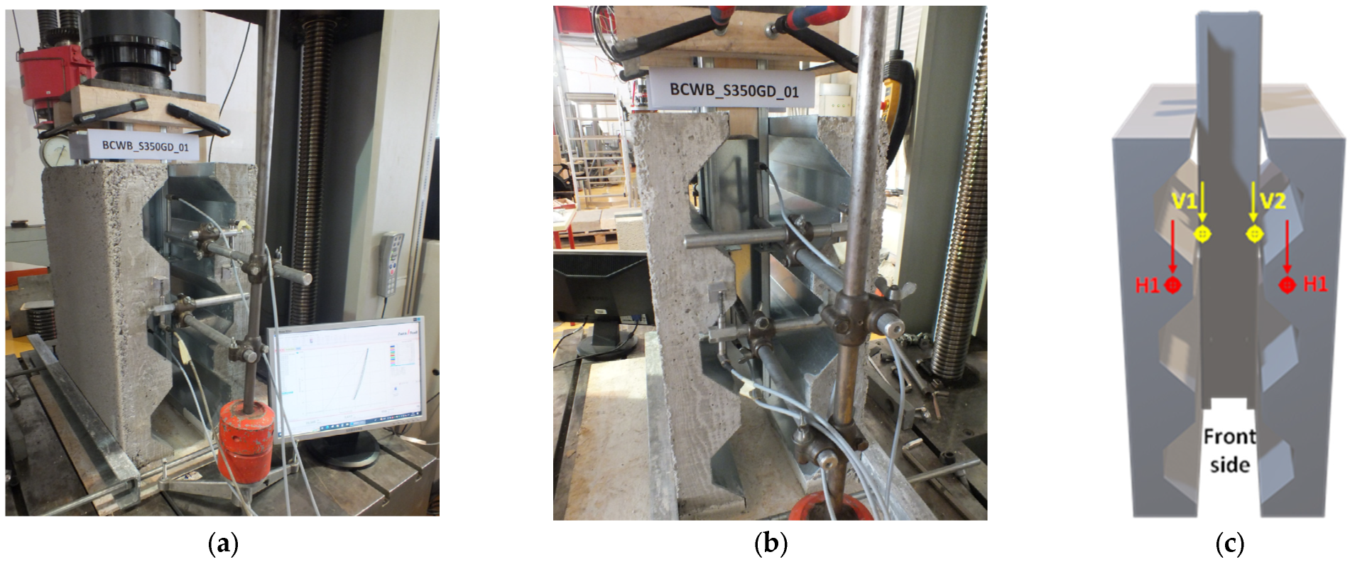
The push-out test was performed with a static testing machine following the test procedure given in EN 1994-1-1, Annex B [27]. As Annex B specifically describes protocols for testing push-out specimens with hot-rolled steel sections, adjustments were made to the test setup to ensure the validity of the results. The modified test setup is shown in Figure 10 and is described below. To achieve the appropriate levelling of the specimens and thereby reduce the load eccentricity, a layer of gypsum was placed under the specimens, following [27]. At the base of the specimens, two hot-rolled C profiles were horizontally placed on both sides of the concrete slabs to avoid specimen displacement. A vertical load was applied through the hinge of the static machine frame directly onto a thick steel plate located at the top of the built-up CFS section specimen. This ensured uniform load distribution across the entire built-up CFS cross-section. Given the use of CFS sections with reduced thickness compared to hot-rolled sections, additional stiffening at the load insertion point was done using rectangular wood elements, which were placed within the top part of the CFS C sections and clamped together (see Figure 10). The reason for this approach was to prevent buckling or undesirable behaviour during the load introduction at the part of the specimen outside the concrete slabs.
In order to monitor individual parameters during the test, eight linear variable displacement transducers (LVDTs) were attached to each specimen, as shown in Figure 10. Specifically, four LVDTs were strategically positioned to track the longitudinal displacement between the CFS section and the concrete slab (two at the front of the specimen (V1–V2) and two at the back (V3–V4)). At the same time, the remaining four LVDTs (H1–H4), two on each side of the specimen, were placed to monitor the insertion of the concrete slab into the gypsum layer. For precise force measurement, a class 1,0 load cell with a 600 kN capacity was installed on the frame of the testing machine to capture the force application. Data acquisition was synchronised via a multi-channel acquisition device (HBM MGCplus) with a sampling rate of 1 sample/s.
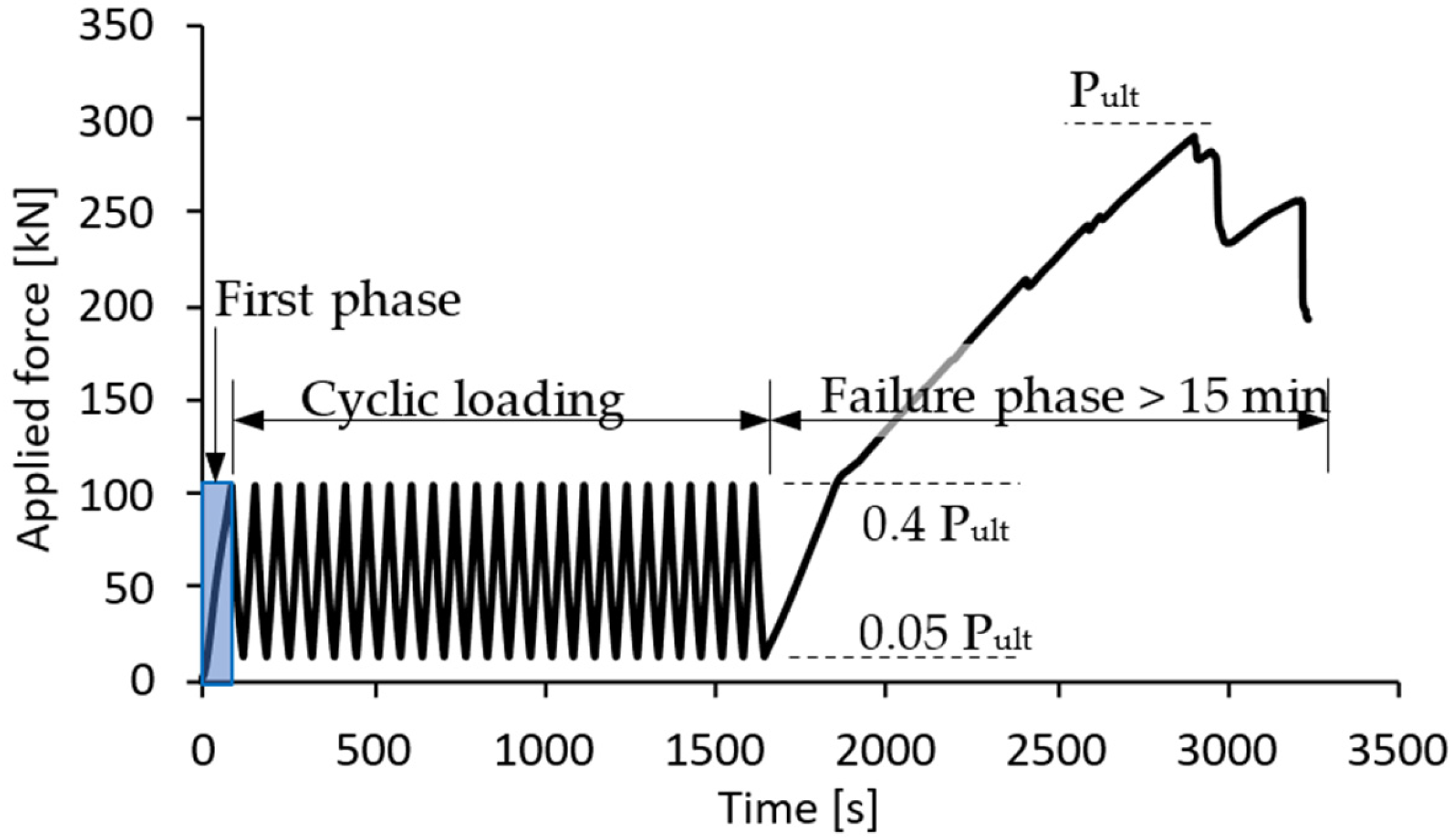
The loading procedure for the specimen was in accordance with the guidelines outlined in EN 1994-1-1, Annex B [27], as shown in Figure 11. Initially, the load was applied gradually up to 40% of the expected failure load. Subsequently, the specimen underwent unloading to 5% of the predicted failure load, followed by the application of 25 load cycles within the range from 5% to 40% of the expected failure load. The shear resistance, which represents the expected failure load, was determined by preliminary numerical analyses and the expressions given in EN 1994-1-1 [27]. However, when predicting the failure load of each specimen, the results from previously tested specimens were also considered. The force control loading was applied to prevent failure of the specimen within 15 min of completion of cyclic loading for the last step of the final loading phase, and a constant load rate of 0.25 kN/s was maintained. The experimental test continued until the force dropped to 20% below the maximum achieved force.

3. Experimental Results of Push-Out Test

3.1. Definitions and Results of Main Parameters

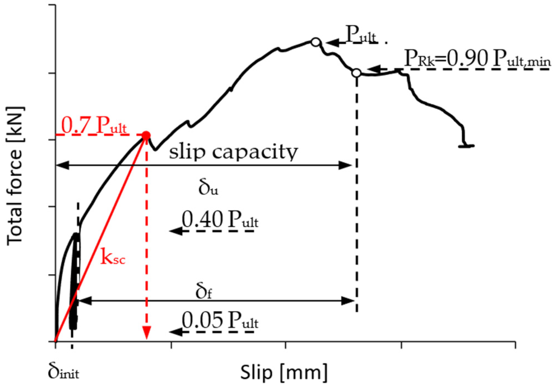
The obtained experimental results were evaluated by comparing key parameters, such as the resistance, ductility, and stiffness, which were defined according to Figure 12. Here, Pult represents the ultimate shear force of the specimens. The longitudinal slip of the specimens is given as the mean value observed across four LVTD sensors. The ultimate slip capacity (δu) is divided into the initial slip (δinit), which occurs from the beginning to the end of cyclic loading, and the additional slip to failure (δf), as defined in Figure 12. The figure also presents the definition of specimen stiffness (ksc), which is determined at 70% of the ultimate shear force within the elastic range.
The statistical evaluation of the experimental results complies with the recommendations in EN 1990:2010, Annex D [34], using the assumed kn factor of 3.37 (as explained in Section 2.2). In addition, the characteristic values of the ultimate shear force and sliding capacity were determined according to EN 1994-1-1, Annex B [27], where the characteristic value is defined as the minimum value of the analysed parameter reduced by 10%. In order to classify the ductility of an individual specimen, it is important to determine the slip capacity of the tested push-out specimens. For a specimen to be considered ductile, the ductility classification according to EN 1994-1-1 [27] requires a characteristic slip to exceed 6 mm.
Table 7, Table 8, Table 9, Table 10, Table 11 and Table 12 summarise the main parameters used to evaluate the push-out test results for all 18 specimens from the BB and BCWB series. Furthermore, the tables also contain a ductility classification and the observed failure mode(s) of the individual specimens. Table 7 does not include the results for specimen BB_01, as this specimen was used as a dummy specimen for the configuration of the push-out test. The coefficients of variation (CoVs) reported for the experimental parameters indicate the scatter and consistency of the test results. The CoV values obtained for the ultimate shear force are generally low and fall within ranges commonly reported in the literature for push-out tests on composite steel–concrete connections, indicating satisfactory repeatability and quality control, and are consistent with assumptions adopted in current design standards.
Higher CoV values were observed for slip-related parameters, which is expected for displacement measurements. Slip is inherently more sensitive to local effects, boundary conditions, measurement resolution, and the progressive development of failure mechanisms. Consequently, greater scatter in slip measurements is commonly accepted in experimental studies and does not compromise the reliability of the measured ultimate resistance.

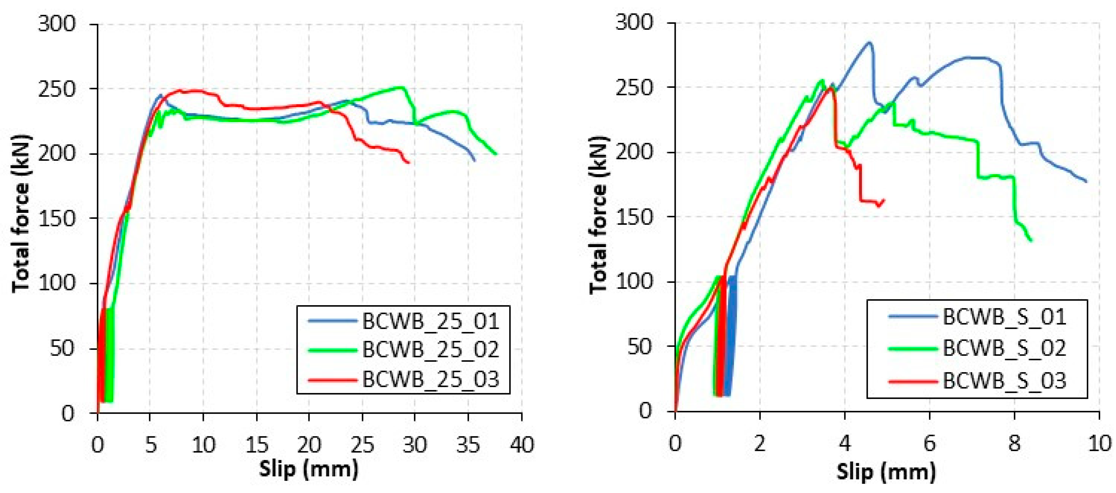
3.2. Force–Slip Curves

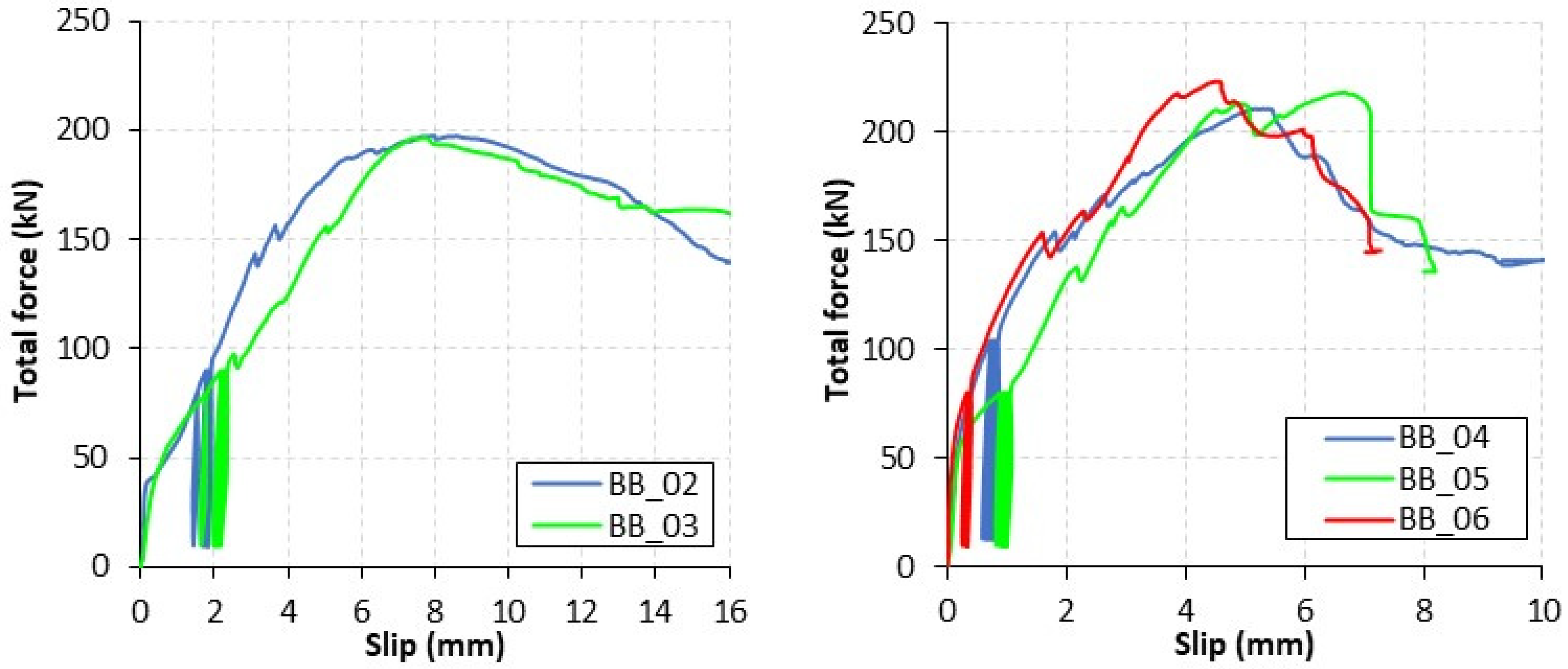
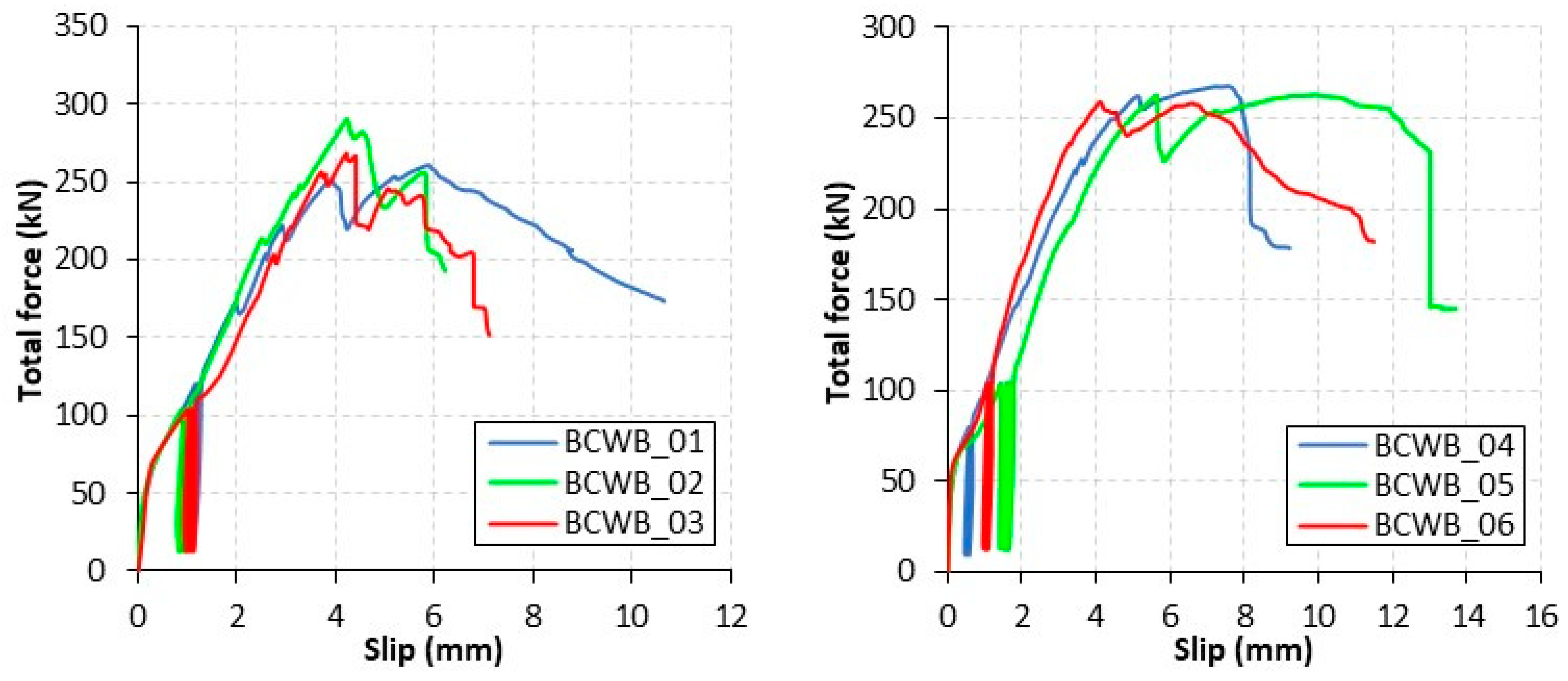
In addition to the tabular representation of the results, this section provides a visual representation of the results using the force–slip curves shown in Figure 13 and Figure 14, illustrating the performances of all 17 push-out specimens. The graphical representation of the curves enhances the understanding of the variations in shear behaviour based on the main parameters mentioned above, which were previously presented in tabular form. Therefore, this combination of tabular data and graphical representation contributes to a comprehensive and detailed presentation of the experimental results.

4. Discussion of Push-Out Test Results

This section deals with the behaviour of the demountable bolted shear connection, analysing the specimens’ resistances, ductilities, stiffnesses and failure modes as described in the previous section. The local load drops and oscillations observed in the force–slip curves are attributed to the progressive engagement and nonlinear behaviour of the bolted shear connection rather than to global instability or premature failure. Initial fluctuations arise from bolt seating within oversized bolt holes, while subsequent oscillations are associated with bearing deformation and elongation of the bolt holes in the thin-walled CFS profiles, as well as the gradual development of concrete cracking related to pry-out failure. The behaviour of the demountable bolted shear connection in the BB and BCWB series and a thorough mutual comparison are explained in separate subsections.

4.1. BB Specimen Series

4.1.1. Failure Modes

To gain a deeper understanding of the differences in the ultimate shear capacity, ductility and stiffness between specimens within the same series, it is first necessary to clarify the longitudinal shear force transmission and the associated failure modes. The thin-walled nature of the CFS sections leads to a complex structural behaviour in which several failure mechanisms may interact simultaneously. When such systems are subjected to longitudinal shear loading, such as in push-out tests, other failure mechanisms can develop in addition to the conventional failure modes, such as shear failure or yielding of the connector and concrete-related failures, including crushing or pry-out, due to the limited thickness of the CFS section. These include bearing failure of the bolt hole, lateral–torsional buckling, local buckling and distortional buckling of the CFS elements.
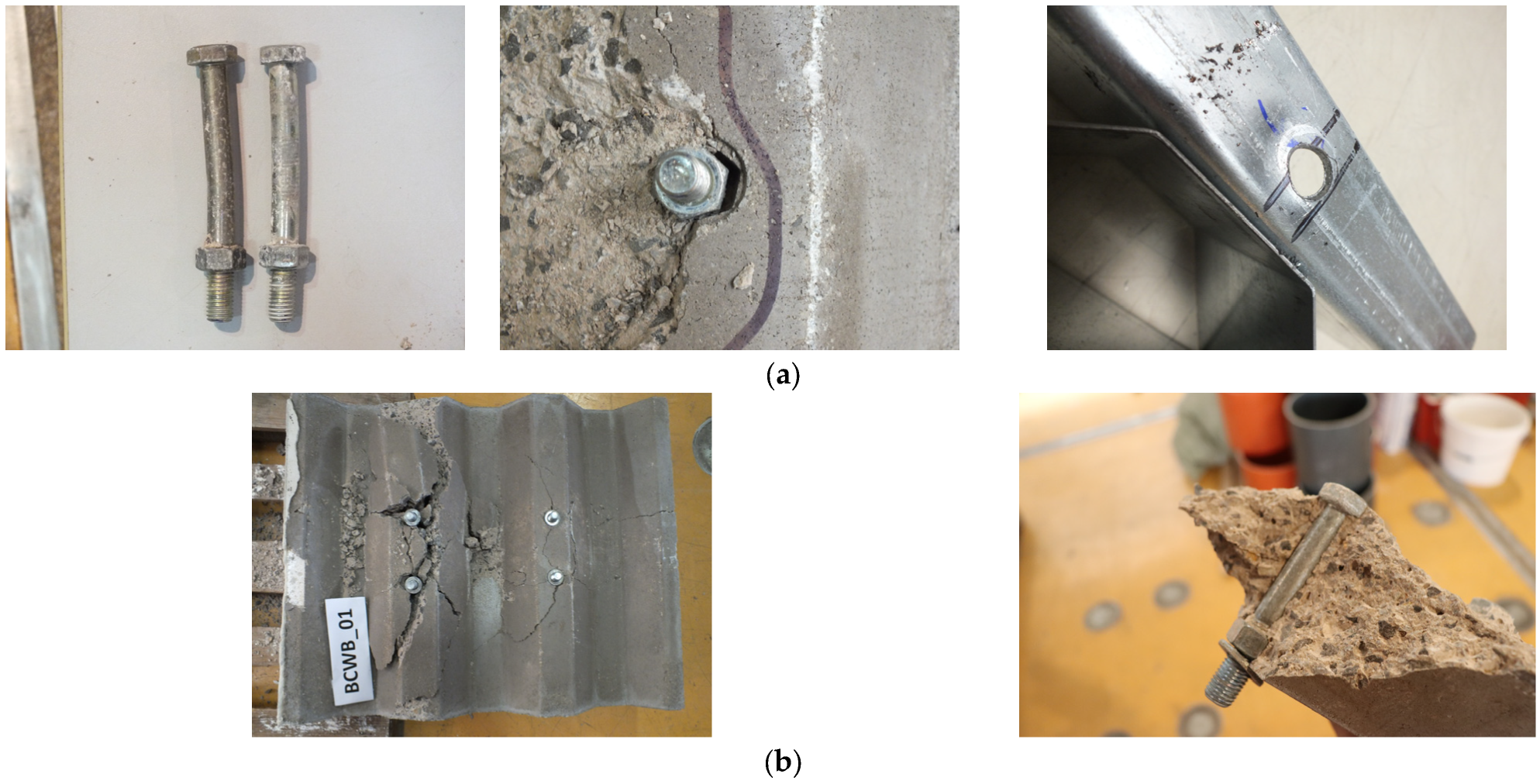
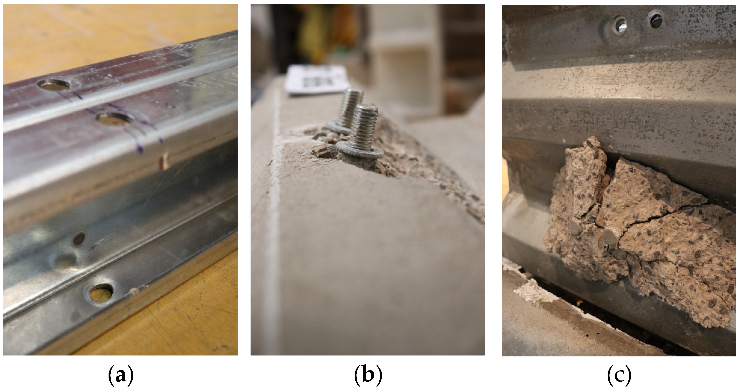
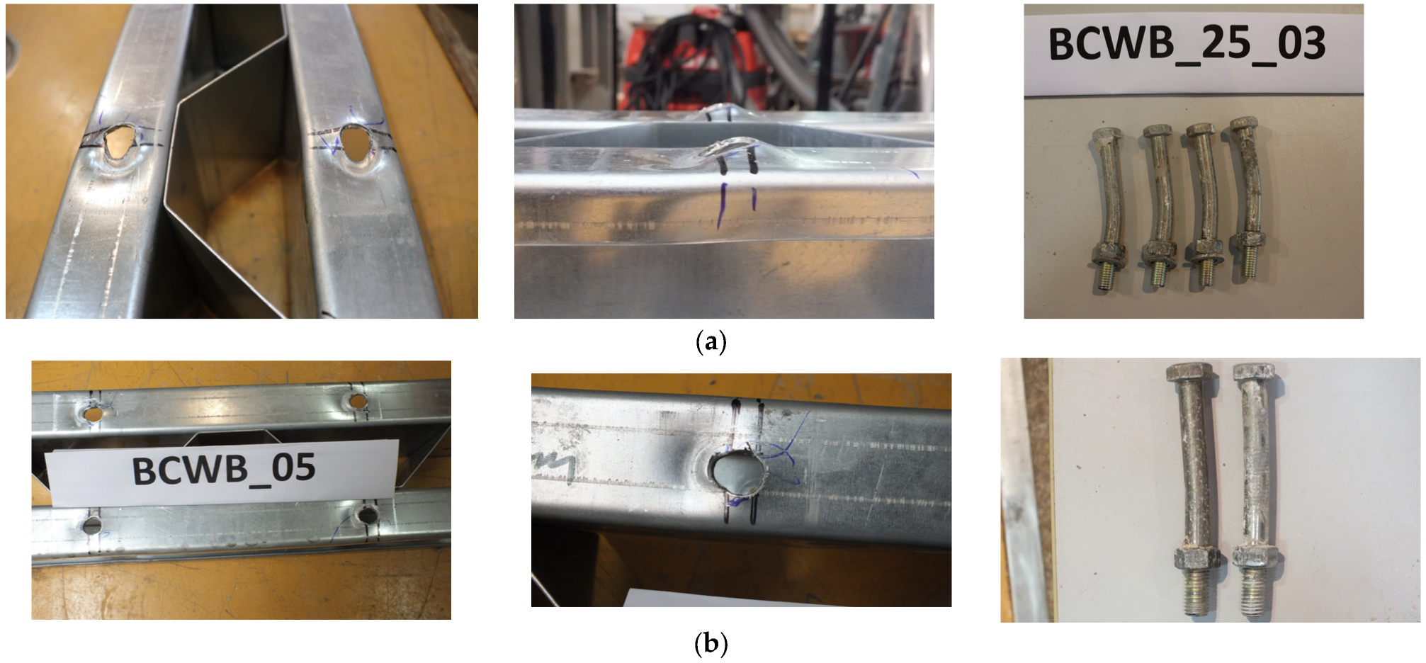
The observed failure modes for the BB series specimens are summarised in Table 7 and Table 8. While concrete pry-out failure was identified as the dominant failure mode for all specimens, three main failure mechanisms were identified in the BB series push-out tests: bearing failure of the bolt hole in the CFS section, bending of the bolt accompanied by plastic hinge formation and concrete pry-out failure. Post-test examinations and disassembly of the specimens revealed that for specimens BB_02 and BB_03 (with 12 mm diameter bolts), the dominant concrete pry-out failure was accompanied by other deformation patterns, including bearing failure of the bolt hole in the CFS section and bending of the bolt accompanied by plastic hinge formation, as shown in Figure 15.
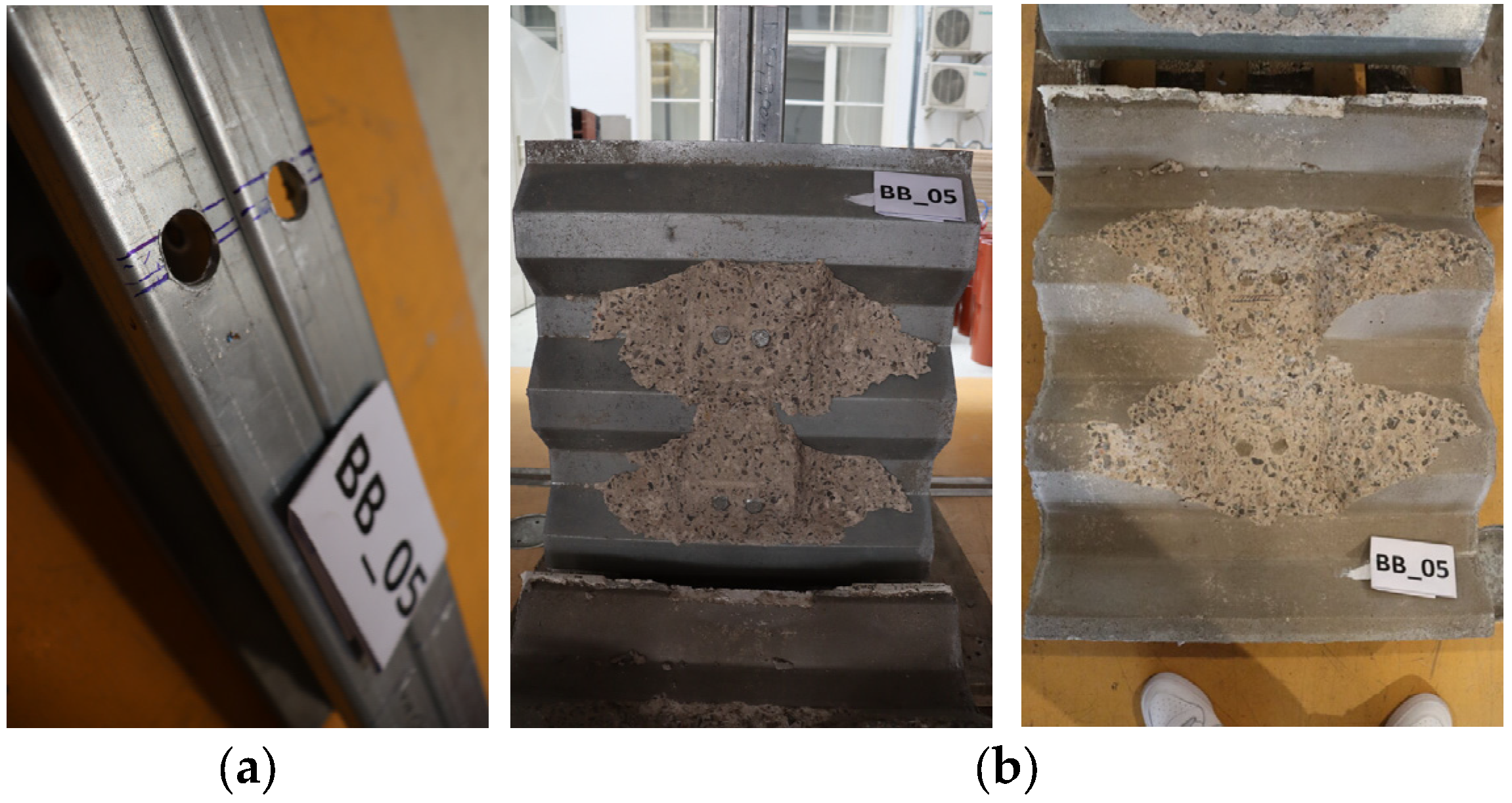
However, when the bolt diameter was increased from 12 mm to 16 mm in specimens BB_04 to BB_06, the observed failure behaviour shifted. Although concrete pry-out remained the dominant failure mechanism, in contrast to BB_02–03, these specimens exhibited only slight elongation of the bolt hole and no visible bending of the bolt, as shown in Figure 16. This change in behaviour can primarily be attributed to the increased cross-sectional area and greater shear capacity of the larger bolts. As a result, the bolts in specimens BB_04–06 did not reach their yield strength before the concrete pry-out failure became dominant. Similarly, the reduced deformation of the bolt hole in the specimens with larger bolts (BB_04–06) can be explained by the increased bearing area at the interface between the CFS section and the bolt, which not only increased the bearing capacity but also concentrated greater localised stresses in the surrounding concrete, thereby triggering the concrete failure earlier compared to the specimens with smaller bolts. These findings indicate that composite CFS–concrete systems, due to the thin-walled nature of the CFS sections, exhibit a complex shear force transfer between components, often resulting in the simultaneous development of multiple deformation patterns.
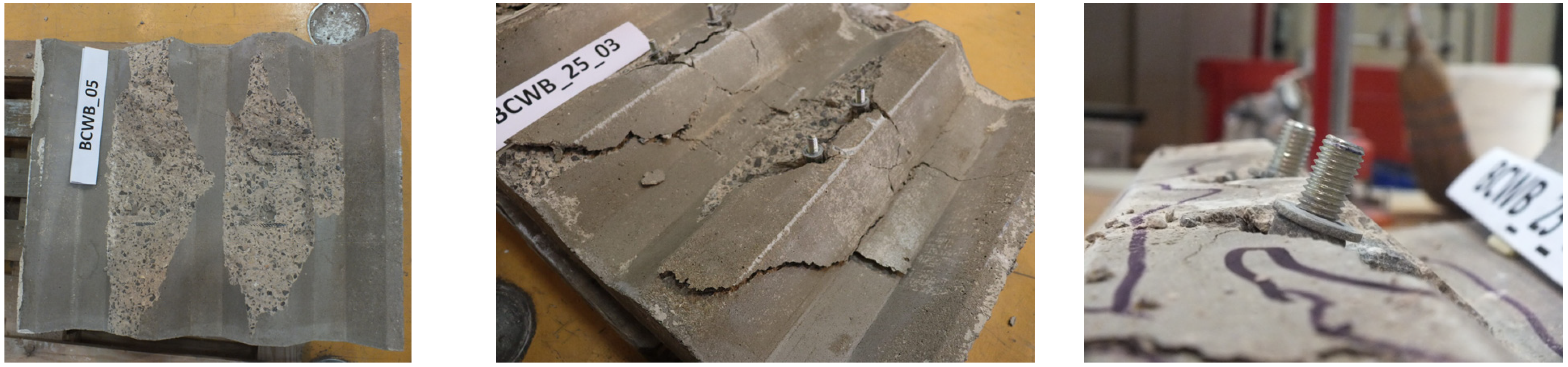
It is also worth noting that during the BB series tests, the development of various cracks in the concrete slabs was observed, as shown in Figure 17. Although these cracks did not lead to the failure of the specimens, it is noteworthy that some of them coincided with the direction of the profiled sheet where the ribs are perpendicular to the CFS beam. Additionally, the formation of diagonal cracks in the rib of the concrete slab was observed during the test, attributed to the separation of the profiled sheeting from the concrete slab (see Figure 17). The subsequent inspection after disassembly provided further insights into the behaviour of the shear connection and confirmed the predicted failure modes observed during the tests.

4.1.2. Ultimate Shear Capacity

Table 7 and Table 8 clearly show the influence of the different bolt diameters on the behaviour of the shear connection in terms of the ultimate shear capacity for the BB series specimens. For the BB series configuration, where there is no corrugated web between the C sections, the minimum and maximum ultimate shear capacities of the bolted connections were recorded as 196.7 kN and 223.2 kN for specimens BB_03 and BB_06, respectively. It is evident that with a constant thickness of the CFS section and concrete quality, an increase in the bolt diameter by 33% resulted in a 7% to 13% increase in the shear capacity of the bolted shear connection. This increase in the shear capacity can be attributed to the larger cross-sectional area of the bolts, which provides higher shear strength, and the increased contact area between the bolt and the CFS section, which ultimately facilitates the full development of the bearing capacity of the concrete. The observed difference in the shear capacity indicates a dependence on the bolt diameter and reflects a transition in the governing failure modes: from a combined deformation of the bolt and the CFS section, where concrete pry-out failure dominates, to a dominant “pure” concrete pry-out failure with only minor deformation of the CFS section. These findings highlight the importance of accounting for the geometric and material properties of components when designing bolted shear connections in composite CFS–concrete systems.

4.1.3. Ductility and Stiffness

When evaluating the behaviour of bolted shear connections in terms of ductility within the BB series, it is observed that specimen BB_02 demonstrates the highest ductile performance, with an ultimate slip of 12.31 mm. This is closely followed by specimen BB_03, which also has a bolt diameter of 12 mm. While the ultimate shear capacity increases with larger bolt diameters, it is essential to note that smaller bolt diameters contribute to the BB series’ more favourable ductile behaviour. In particular, increasing the bolt diameter by 33% results in a reduction in the ultimate slip by approximately 86%, indicating a shift in the shear force transfer and consequently a change in the governing failure mechanisms. This trend is supported by the experimental data presented in Table 7 and Table 8 and is explained by the interaction of different failure mechanisms described in Section 4.1.1. Specifically, specimens BB_02 and BB_03 with smaller-diameter bolts exhibited greater ductility, as the smaller bolts are more prone to the plastic deformation (bending and yielding) and localised deformation of the CFS section before the concrete pry-out failure. This behaviour allows for greater energy dissipation and a greater slip capacity before ultimate failure. Conversely, specimens with larger-diameter bolts showed lower ductility, as the interaction between steel and concrete became minimal and the slip capacity was predominantly dependent on the brittle concrete pry-out failure. Despite these differences, most specimens were classified as ductile, with the exception of specimen BB_04, which exhibited an ultimate slip capacity of 5.90 mm.
In terms of stiffness, the experimental results demonstrate that bolted shear connections with larger bolt diameters have a higher initial stiffness. This increase is primarily due to the larger cross-sectional area of the bolts, which improves the efficiency of the load transfer between the steel and concrete components, thereby reducing the relative slip under shear loading. A smaller bolt diameter means a reduced cross-sectional area for the transfer of forces and a smaller contact area between concrete and steel, which can lead to increased slip and the less efficient transfer of shear forces. Consequently, higher stresses develop in the bolt under the same load, making it more prone to plastic deformation, which reduces the overall stiffness of the shear connection.
Optimising the bolt diameter is critical to ensure the serviceability of composite structures by controlling deflection and maintaining structural integrity under longitudinal shear loading. Using excessively large bolts may lead to stiff but brittle shear connections, while smaller bolts increase ductility at the expense of reduced shear capacity. Ideally, a balance between the shear capacity, ductility and stiffness should be achieved based on the structural requirements and the intended behaviour of the bolted shear connection in composite CFS-concrete systems.

4.2. BCWB Specimen Series

4.2.1. Failure Modes

Following a similar approach to the BB series specimens, it is important to first identify the dominant failure mechanisms in the BCWB series. In contrast to the BB series, the BCWB specimens not only differ in the bolt diameter but also in the thickness and steel grade of the CFS section. In addition, these specimens contain corrugated webs between the CFS C profiles, which leads to the increased longitudinal spacing of the shear connectors compared to the BB series. In all BCWB specimens, the dominant failure mechanism was identified as concrete pry-out failure, characterised by the formation of conical cracks around the rib of the concrete slab. In addition to this primary failure mechanism, additional mechanisms, such as the bearing failure of the bolt hole in the CFS section and yielding of the bolt, were also observed. These deformation patterns interact with concrete pry-out failure, resulting in more complex behaviour in bolted shear connections.
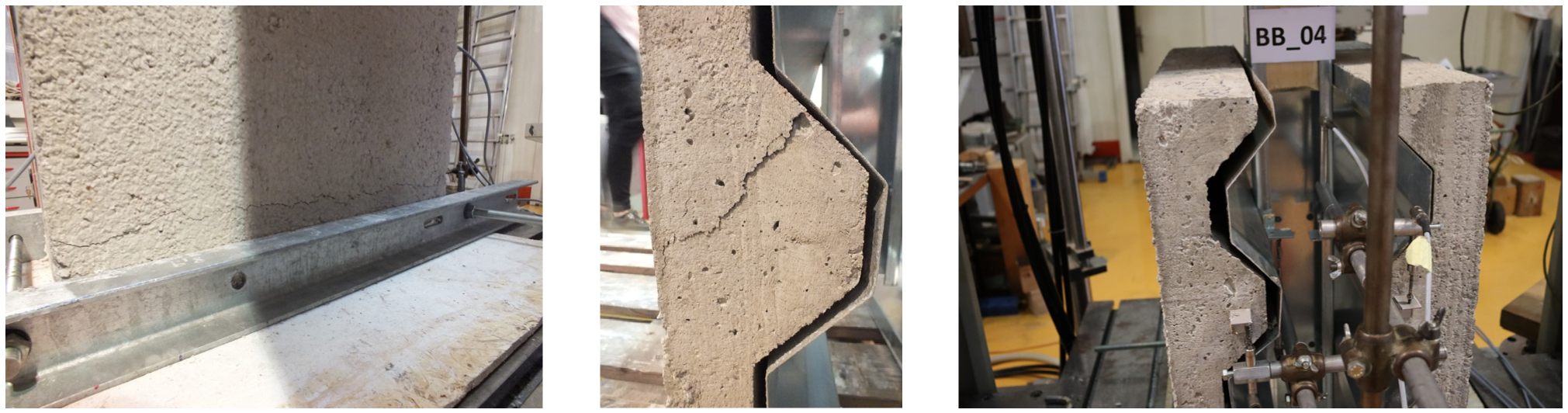
For specimens BCWB_01–03 and BCWB_04–06, where only the bolt diameter was varied, the exact failure mechanisms were observed as those in the BB series. The interaction of multiple failure modes across specimens is evident, as shown in Figure 18.
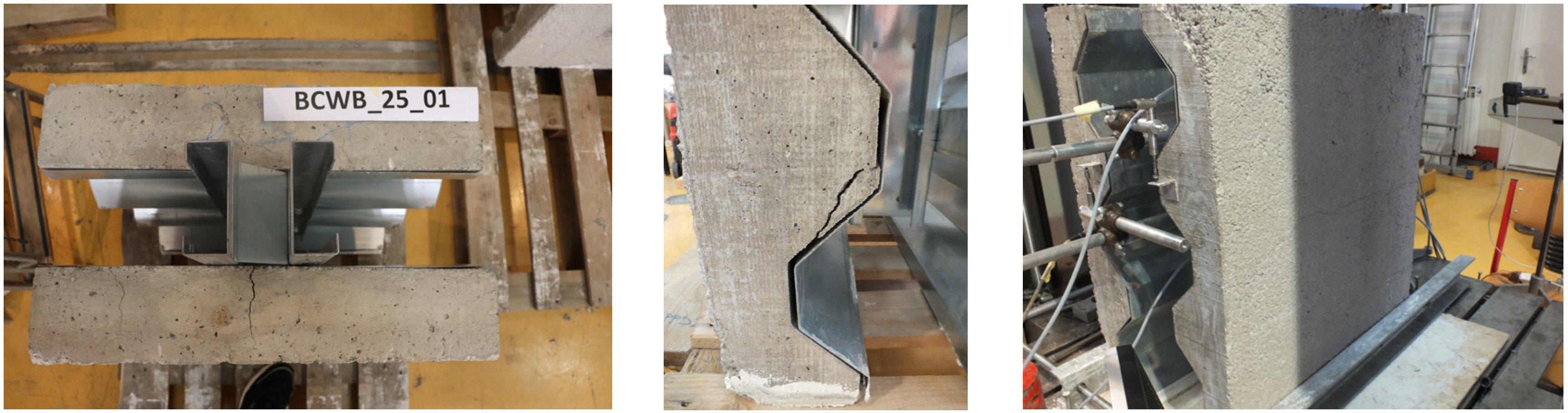
Furthermore, the effect of varying the CFS C-profile thickness on the failure mechanisms was investigated by comparing the BCWB_04–06 and BCWB_25_01–03 specimen series. Although both series exhibited the same dominant failure mechanism (as shown in Table 10 and Table 11), a detailed analysis revealed a significant elongation of the bolt holes and yielding of the bolts, accompanied by plastic hinge formation in the BCWB_25_01–03 specimens. These effects indicate a greater involvement of the steel component in the shear force transfer and a greater stress distribution within the steel section compared to the BCWB_04–06 series (see Figure 19). In contrast, the BCWB_04–06 specimens showed a stiffer response with limited deformation of the hole and moderate bending of the bolt, indicating a more balanced interaction between concrete pry-out, bolt yielding and the bearing of the CFS section. The more pronounced deformations in the BCWB_25_01–03 specimens can be attributed to the reduced thickness (2.5 mm) of the CFS section. This thinner section is more prone to localised yielding and deformation under loading, resulting in greater slip and plastic deformation before failure. Nevertheless, both series ultimately exhibit the same failure mode (see Figure 20), i.e., concrete pry-out failure, which is associated with a drop in force after the plastic plateau in the force–slip curves.
In addition to the influence of the profile thickness and bolt diameter, the influence of the CFS grade was investigated by comparing specimens BCWB_01–03 (DX51D) and BCWB_S_01–03 (S350GD). The results show that the change in steel grade had no significant effect on the observed failure mechanisms. Both series exhibited predominantly concrete pry-out failure, accompanied by minor elongation of the bolt hole in the CFS section. This suggests that the behaviour of the bolted shear connection under the tested configurations and loading conditions is more influenced by the geometry and interaction of the components than by moderate variations in the steel strength.
Moreover, the cracks observed during the test did not lead to the failure of the specimens. Notably, the orientation of these cracks aligned with the direction of the ribs in the profiled steel sheeting, as shown in Figure 21, which further illustrates the complex stress distribution within the composite system.

4.2.2. Ultimate Shear Capacity

Table 9, Table 10, Table 11 and Table 12 clearly demonstrate the influence of the bolt diameter, CFS section thickness and steel grade on the behaviour of the shear connection in terms of the ultimate shear capacity for the BCWB series specimens. The first focus is on discussing the influence of the bolt diameter on the behaviour of the BCWB series. A similar trend to that of the BB series specimens was observed: increasing the bolt diameter from 12 mm to 16 mm resulted in a 4% increase in the ultimate shear capacity of the bolted shear connection. As mentioned above, this improvement is attributed to the larger cross-sectional area of the bolts, which increases their shear strength and the contact area with the CFS section. This, in turn, allows the full development of the bearing capacity of the surrounding concrete to be realised, a condition that is less possible with smaller-diameter bolts.
Regarding the effect of the thickness of the CFS section, a comparison between specimens BCWB_04–06 and BCWB_25_01–03 (as shown in Table 10 and Table 11) reveals that a reduction in the thickness of the CFS section from 3.0 mm to 2.5 mm, i.e., a reduction of approximately 20%, leads to a decrease in the shear capacity of between 3% and 9%. Although this decrease is relatively moderate, it can be explained by the reduced bearing capacity of the CFS section and its increased susceptibility to localised plastic deformation. Consequently, the interaction between steel and concrete becomes more pronounced, leading to a lower ultimate shear capacity of the bolted shear connection.
Finally, the influence of the steel grade was investigated by comparing the BCWB_01–03 specimens made of DX51D steel and the BCWB_S_01–03 specimens made of S350GD steel. Despite the 25% increase in the yield strength and ultimate strength of the S350GD material, only a 4% increase in the shear capacity was observed. This finding confirms that the mechanical properties of the steel section had only a limited influence on the ultimate shear capacity in the tested configuration. Instead, the behaviour of the bolted shear connection appears to have been primarily determined by the geometrical parameters and the interaction between the components rather than by the mechanical properties of the steel section.

4.2.3. Ductility and Stiffness

Table 9, Table 10, Table 11 and Table 12 also provide valuable insight into the ductility and stiffness of the tested bolted shear connections, highlighting the influence of the geometrical and material characteristics, as well as the failure modes, on the overall mechanical performance of the connections.
Starting with the ductility, a clear difference can be made between specimens with and without deformation of the bolt. Specimens BCWB_01–03 and BCWB_S_01–03, where the failure mode was dominated by concrete pry-out failure accompanied by minor bearing of the CFS section, generally exhibited brittle behaviour in two out of three tests per series, with ultimate slip values (δu) < 6 mm in most cases. The lack of yielding of the bolts combined with a pronounced elongation of the bolt hole in the CFS section substantially limited the plastic deformation capacity of the connections. As a result, the specimens exhibited sudden and brittle failure immediately after the peak at the ultimate force. This behaviour was particularly pronounced in specimens BCWB_S_03 and BCWB_03, which only achieved slip values of δu = 3.80 mm and δu = 5.80 mm, respectively.
In contrast, the presence of bolt deformation within the interaction of the failure mechanisms, as observed in specimens BCWB_04–06 and BCWB_25_01–03, significantly increased the ductility of the bolted shear connection. These specimens consistently exhibited fully ductile behaviour across all tests, with ultimate slip values exceeding 8 mm and reaching up to 35 mm in specimen BCWB_25_02. Notably, the BCWB_25 series exhibited the highest ductility among all tested configurations. This behaviour is attributed to the favourable interaction between the deformation of the bolts and the surrounding concrete, which allows for a more uniform load redistribution before failure.
When analysing the stiffness, an inverse relationship with ductility becomes evident. Specimens from series BCWB_01–03 and BCWB_S_01–03, which have larger bolt diameters (16 mm), exhibited higher initial stiffness values (e.g., 86.2 kN/mm for BCWB_02 and 89.0 kN/mm for BCWB_S_02) compared to other configurations with smaller bolt diameters. This increased bolt diameter leads to a stiffer shear connection, which consequently limits the ability for plastic deformation and leads to a generally lower ductility. Such behaviour is attributed to the early concentration of stresses and the limited load redistribution in these shear connections. In contrast, the ductile specimens from BCWB_04–06 and BCWB_25_01–03, which have smaller bolt diameters, exhibited moderate-to-lower stiffness values (e.g., 59.9–70.6 kN/mm). This reduced stiffness enables larger deformations under longitudinal shear loading and a more progressive degradation of stiffness, resulting in improved ductility and energy dissipation. In summary, the results confirm that ductility is strongly influenced by the activation of bolt deformation accompanied by elongation of the bolt hole in the CFS section, while stiffness is primarily determined by the initial connection geometry and the inherent stiffness of the materials. Specimens that allow for the full development of yielding and interaction between steel and concrete, such as those in the BCWB_25 series, demonstrated the optimum balance between the deformability and ultimate shear capacity. For structural applications prioritising ductility and energy dissipation, configurations that allow for effective interaction between bolt deformation and concrete pry-out failure while avoiding overly rigid systems should be favoured.

4.3. Influence of Corrugated Web

This section investigates the influence of introducing an additional CFS element (corrugated web) on the behaviour of shear connections. The analysis includes the specimens BB_01–03, BB_04–06, BCWB_01–03 and BCWB_04–06, whereby a distinction is made between the specimens with and without corrugated webs, as outlined in Table 7, Table 8, Table 9 and Table 10. Examining the results shown in Table 7, Table 8, Table 9 and Table 10 in conjunction with an investigation of the force–slip curves shows a significant increase in the ultimate force of around 25% when a corrugated web is inserted between the CFS profiles. Regarding the ductility and initial stiffness, there are no significant differences between the BB and BCWB series for the specimens with 16 mm bolts. However, a clear difference can be seen in the specimens with 12 mm bolts, displaying a 20% variance in the ductility and an 80% distinction in the initial stiffness between the two series. These observed differences can be attributed to the delayed or uneven placement of the bolts on the wall of the holes in the CFS profile. In addition, these deviations may be due to slight movements of the specimen during the test. Apart from the recognised improvement in the overall stability of the specimen due to the additional corrugated web, the results show a more favourable behaviour of the shear connection in terms of ultimate force. The reason for this behaviour is presumably the increased transverse spacing between the shear connection, which is approximately 2.2 times greater due to the addition of the corrugated web. It is assumed that this increased transverse spacing facilitates the development of the full concrete bearing capacity of the shear connector. In the specimens from the BB series, where the transverse spacing is smaller than that in the BCWB series, there is an earlier overlap of the zones where concrete cracks occur around the individual shear connection. This, in turn, obstructs the full development of the concrete bearing capacity and leads to a lower ultimate force than that of the specimens of the BCWB series.
The observed improvement in the shear strength and the differences in the ductility between the BB and BCWB series are not only attributed to geometrical changes, such as the increased transverse spacing of the connectors, but may also be influenced by more complex interactions within the built-up CFS cross-section. Adding a corrugated web increases the overall stiffness and stability of the built-up CFS girder, which helps maintain better alignment between the steel and concrete components throughout the test, thereby reducing eccentricities and localised deformations that would otherwise lead to premature failure.
In addition, the corrugated web acts as an additional restraint against the lateral displacement or rotation of the flanges, especially when deformed by longitudinal shear loading. This restraining effect may delay the onset of local buckling near the bolt holes or reduce the elongation of the bolt holes, which, in turn, leads to the improved performance of the shear connection.

5. Comparison with Analytical Predictions

This section compares the experimentally obtained results of the ultimate force for demountable bolted shear connections with various analytical predictions. Six analytical methods and four different standards were used to provide a comprehensive assessment: EN 1994-1-1:2004 [27], prEN 1994-1-1:2023 [28], JSCE [29], AS2327.1-2003 [30] and AISC 360-10 [31]. Notably, most of the equations within these standards deal primarily with analytical procedures for shear stud connections in composite connections. However, an exception is found in prEN 1994-1-1:2023 [28], which deals specifically with the shear resistance of bolted shear connections in solid slabs. In addition, it is important to emphasise that although the analytical procedures relate predominantly to headed studs, equations are also given for conventional composite systems involving the application of hot-rolled sections. Therefore, this section aims to investigate the suitability of these equations in determining the resistance of bolted shear connections in composite CFS-concrete systems. Through this investigation, a deeper understanding of the applicability and accuracy of these analytical approaches in a variety of configurations and materials will be gained.
The current and newly proposed generation of the Eurocode [27,28] introduces an analytical procedure for calculating the nominal shear strength of a single-headed stud shear connector. Therefore, the following procedure is designed for application in steel-concrete composite beams with solid concrete slabs:
P R k = min P R k , S , P R k , C ,
where PRk,S represents the resistance of the shear connection when the failure occurs through the steel shear connector, and PRk,C is the resistance of the connection when the concrete failure occurs around the shear connector.
The characteristic failure resistances for shear connection and concrete can be determined using the following equations:
P R k , S = 0.8 · f u · π · d 2 4 ,
P R k , C = 0.29 · k c c · d 2 f c k · E c m
where d represents the diameter of the stud (16 mm ≤ d ≤ 25 mm), and fu is the ultimate tensile strength of the material of the shear connector but is not greater than 500 N/mm2. In addition, fck and Ecm designate the characteristic cylinder compressive strength and the modulus of elasticity of concrete, respectively, while kcc is a reduction factor considering the effect of concrete relaxation under sustained loading.
The recently introduced Eurocode prEN 1994-1-1:2023 [28], in Annex G, presents an analytical procedure for determining the resistance of headed studs used with open-trough profiled steel sheeting in buildings with ribs transverse to the supporting beams. The feasibility of this procedure depends on the fulfilment of the geometric conditions specified in Annex G. The design shear resistance is determined as the smaller value of Equations (5) and (6):
P R k , S = 0.58 · f u · π · d 2 4 ,
P R k , C = k c c   ·   C 2 · k u f c t k , 0.05 · W s c h p · n r + n y · M p l , s c 0.82 · h p d / 2
Following Annex G, the correction factors C2 and ku are derived from tables and equations. The parameter fctk, 0.05 denotes the characteristic value of the tensile strength of concrete, and Wsc denotes the modulus of flexion. In addition, nr stands for the number of stud connections within one rib at the beam intersection, while ny and Mpl,sc denote the number of yield hinges and the plastic bending resistance of the shear stud, respectively.
In addition to Equations (3)–(6) mentioned above, an analytical procedure for determining the shear resistance of non-preloaded bolts as shear connections in solid slabs has been introduced in the new generation of the Eurocode [28]. The design shear resistance of a non-preloaded bolt may be assumed to be the smaller of the following values:
P R k , S = α b · A s · f u 4 ,
P R k , C = 55 · α c · d 1.9 f c k · h s c d 0.4 + 22,000
where As is the tensile stress area of the bolt, and hsc represents the overall nominal height of the bolt in a concrete slab.
It is worth mentioning that the Eurocode is characterised by considering the reduction factor for a profiled concrete slab. Therefore, Equations (3)–(8) are multiplied with the corresponding reduction factor kt, having a specific value of 0.58 for this type of configuration of the system, as calculated from the following equation:
k t = 0.7 n r b o h p h s c h p 1 ,
Referring to the Japanese Standard Specifications for Steel and Composite Structures JSCE [29], the analytical procedure for calculating the shear resistance of welded headed studs in concrete failure is given by the following equation:
P c , J S C E = 31 · A s f c m · h s c / d + 10,000 ,
The design guidelines for the resistance of welded headed studs in a solid floor slab following AS2327.1-2003 [30] are organised according to two possible failure modes. The following equations express this:
P A S = min 0.63 · d 2 · f u                         0.31 · d 2 f c k · E c m         ,
The proposed equations in AISC 360-10 [31] for determining the shear capacity of headed studs and channel shear connection were also considered in this study and are given as:
P A I S C = min 0.5 · A s f c k · E c m R g · R p · A s · f u ,
where Rg and Rp are correction factors taken as 0.85 and 0.6, respectively.
The analytical predictions included all potential failure mechanisms identified based on previous research findings. However, it is important to highlight that the governing value used for comparison with the experimental results was the shear connection resistance associated with the failure of the concrete. This was chosen because the analytical values for this failure mode were the lowest among all considered mechanisms and thus represented the most critical scenario for design and evaluation purposes. Therefore, the ultimate shear load capacities of the experimental specimens are compared with the analytical predictions according to the above standards, as shown in Table 13.
A comprehensive comparison between various analytical models and the experimental results was conducted to evaluate their prediction accuracies for the shear resistance of bolted shear connections in CFS–concrete composite systems, as summarised in Table 13. The results revealed significant discrepancies in both the magnitude of the predicted resistance and the consistency of the predictions across different specimens.
Among the six evaluated approaches, the model labelled PEC4(2), derived from Equations (5) and (6) based on prEN 1994-1-1:2023 [28], demonstrated the highest accuracy and consistency. It achieved a mean ratio of analytical-to-experimental resistance of 1.00 and the lowest coefficient of variation of 16%, indicating both precision and robustness under different configurations. These results indicate that PEC4(2) effectively captures the actual shear behaviour of the investigated shear connection, partially accounting for the interaction effects between failure mechanisms such as concrete pry-out, bolt hole bearing and bolt bending.
In contrast, the original EC4 expression PEC4(1) showed a similar mean value of 1.01 but a much higher coefficient of variation of 29%, suggesting conservative estimates combined with notable scatter. While conservative predictions are generally preferred in the design of structures, the high variability could lead to inconsistent safety margins and the inefficient use of materials.
A similar pattern was observed for PEC4(3), which also resulted in conservative predictions with a moderate coefficient of variation, yet it suggests limited reliability in capturing the actual shear resistance of the bolted shear connectors in CFS–concrete systems for the considered failure modes.
The JSCE model [29] provided the most conservative predictions with a mean ratio of 2.53, more than double the experimentally observed resistance. Despite a coefficient of variation of 21%, this significant overestimation indicates a limited applicability for bolted shear connectors in CFS–concrete systems.
The approaches based on AS2327.1 [30] and AISC [31] also achieved mean ratios of 2.00 and 1.58, respectively, with high coefficients of variation (29% for both). All evaluated models, which were originally developed for hot-rolled steel beams with welded studs, appear to be poorly suited for thin-walled bolted configurations, as they do not take into account the interactions of the failure modes that occur in composite CFS-concrete systems.
Furthermore, it should be noted that although these equations were initially formulated for hot-rolled sections in composite systems, they still provide valuable insights into the complicated behaviour of shear connections in composite CFS concrete systems. As already highlighted, the small thickness of CFS sections contributes to the complex behaviour of the shear connection, where the interaction of different failure modes is manifested. These findings underscore the importance of selecting an analytical model that is designed with the structural characteristics of the system under consideration. In this context, PEC4(2) proves to be the most promising base model for further refinement. While the performance of the model is encouraging, the variability in the predictions across the different specimen configurations indicates further potential for improvement.
To enhance the predictive accuracy and reduce the scatter of the results, the influence of the CFS thickness, bolt diameter and transverse spacing of connectors should be included in the analysis as normalisation parameters. Based on the experimental results, two distinct correction factors (kf) are proposed to improve the accuracy of the analytical model PEC4(2) depending on the transverse spacing of the shear connectors:
P m o d e l , c o r r e c t e d = k f · P E C 4 2 P u l t , e x p
  • For the transverse spacing of shear connectors ≤ 50 mm (BB series):
k f = 12.5 d · 1 + 0.02 · 2.5 t ,
  • For the transverse spacing of shear connectors > 50 mm (BCWB series):
k f = 12.5 d · 1.1 + 0.075 · 2.5 t ,
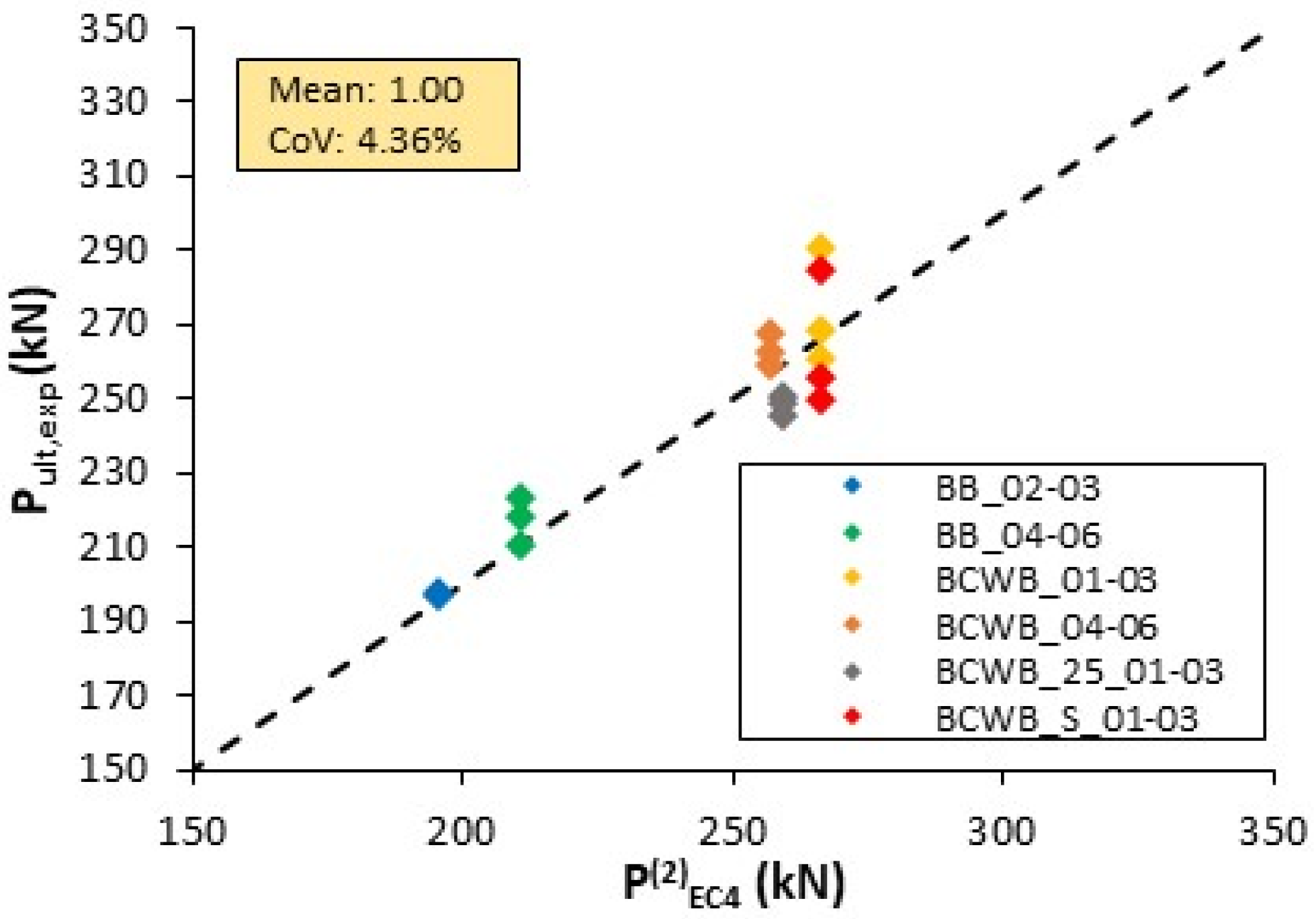
The application of the proposed correction factor to the analytical expression of PEC4(2) led to a significant improvement in the prediction accuracy, as shown in Figure 22. The corrected model achieved a mean ratio of analytical-to-experimental resistance of 1.00, indicating that the analytical predictions are in very good agreement with the experimental data. More importantly, the coefficient of variation was reduced from 16% to only 4.36%, representing a significant reduction in the scatter of the results.
This significant reduction in scatter clearly demonstrates the effectiveness of the correction factor in improving the consistency of the resistance predictions across various specimen configurations. All data points cluster closely around the line of perfect agreement, highlighting the ability of the model to reliably capture the actual shear behaviour of bolted connections in composite CFS-concrete systems.
However, to ensure the global reliability and robustness of the proposed correction factors, further numerical parametric studies are recommended. These studies should consider a wider range of geometric configurations, material properties and boundary conditions to verify that the correction factor maintains its accuracy under different design scenarios. Such validation is essential to confirm the reliability of the adapted model for practical design applications beyond the scope of the current experimental research.

6. Conclusions

This study investigated bolted shear connections in composite systems consisting of built-up CFS sections and concrete slabs through a series of standard push-out tests. The experimental programme was designed to evaluate the influence of several key parameters on the performance of the shear connection, including the transverse spacing of the bolts, the diameter of the bolts, and the thickness and strength of the CFS sections. As a result, the effects of these variables on the ultimate load, failure mode, ductility and stiffness of this particular shear connection were then analysed and discussed in detail. The main conclusions from this study are presented below:
  • The experimental investigation revealed the complex behaviour of bolted shear connections, characterised by the interaction of multiple failure mechanisms that influence both the ultimate resistance and ductility. While concrete pry-out failure was consistently the dominant mode, secondary mechanisms such as the bearing deformation of bolt holes and bolt yielding were frequently observed, particularly in specimens with thinner CFS sections or smaller bolt diameters. These interaction effects are not sufficiently addressed in the current design codes, highlighting the need for more advanced analytical models that can account for the complex behaviour of composite CFS-concrete systems.
  • Increasing the bolt diameter from 12 mm to 16 mm increased the ultimate shear resistance by 7–13% in the BB series and by approximately 4% in the BCWB series while reducing the characteristic slip capacity from 10–12 mm to 4–6 mm. A pronounced increase in the initial stiffness of up to 90% was observed in the BB series, indicating that larger bolt diameters enhance resistance and stiffness at the expense of ductility due to earlier concrete pry-out activation.
  • Reducing the CFS thickness from 3.0 mm to 2.5 mm led to a moderate reduction in the shear resistance (3–9%) but significantly increased the ductility, with the mean ultimate slip capacity exceeding 30 mm (>200%). In contrast, increasing the CFS yield strength from DX51D to S350GD (≈25%) resulted in only a marginal resistance increase (~4%) and reduced ductility, confirming that the connection response is governed primarily by the geometry and failure mode interaction rather than by the material strength.
  • The incorporation of a corrugated web between the CFS profiles was shown to have a pronounced influence on the behaviour of the shear connection by increasing the transverse spacing between connectors. Compared to the BB configuration, the BCWB specimens exhibited an increase in ultimate shear resistance of approximately 30–40%, demonstrating the strong sensitivity of the shear capacity to the connector spacing and load distribution in composite CFS–concrete systems.
  • The existing analytical expressions from current standards do not accurately evaluate the shear resistance of composite CFS-concrete systems. The application of a spacing-dependent correction factor to the analytical model from prEN 1994-1-1 [28] significantly improved its prediction accuracy, reducing the coefficient of variation from 16% to 4.36% and achieving a good mean resistance ratio of 1.00, thereby demonstrating its potential for the reliable prediction of the resistance of the bolted shear connection in composite CFS-concrete systems.
This study underlines the importance of future research efforts in this area to provide a more sophisticated understanding of the complexity of the behaviour of bolted shear connections in CFS-concrete composite systems. Therefore, future research should focus on the development of detailed finite element models to simulate the push-out tests presented in this study, enabling an extensive parametric investigation of the key governing parameters, such as the thickness of the CFS sections, the concrete strength, the bolt geometry, and the geometry of the profiled steel sheeting. The numerical results will subsequently be used to perform a comprehensive probabilistic assessment of the proposed analytical expression for bolted shear connections, with particular emphasis on evaluating the reliability level and the adequacy of the adopted partial safety factors.

Author Contributions

Conceptualisation, V.Ž., I.Ć. and I.L.; methodology, V.Ž. and I.Ć.; software, V.Ž.; validation, V.Ž. and I.Ć.; formal analysis, V.Ž.; investigation, V.Ž., I.Ć., I.L., A.R. and M.B.; resources, V.Ž., I.Ć., I.L., A.R. and M.B.; data curation, V.Ž.; writing—original draft preparation, V.Ž.; writing—review and editing, V.Ž., I.Ć., I.L., A.R. and M.B.; visualisation, V.Ž.; supervision, I.Ć. and I.L.; project administration, I.L.; funding acquisition, I.L. All authors have read and agreed to the published version of the manuscript.

Funding

This research was partially funded by the Croatian Science Foundation, grant number UIP 2020-02-2964 (LWT-FLOOR project—Innovative lightweight cold-formed steel—concrete composite floor system); project leader: Ivan Lukačević.

Data Availability Statement

Dataset available on request from the authors.

Conflicts of Interest

Author Vlaho Žuvelek was employed by the company Stabilnost Ltd., Split, Croatia. The remaining authors declare that the research was conducted in the absence of any commercial or financial relationships that could be construed as a potential conflict of interest.

References

  1. Firoozi, A.A.; Oyejobi, D.O.; Avudaiappan, S.; Flores, E.S. Emerging trends in sustainable building materials: Technological innovations, enhanced performance, and future directions. Results Eng. 2024, 24, 103521. [Google Scholar] [CrossRef]
  2. Nawar, M.T.; Silem, O.A.; Ibrahim, I.; Maaly, H.M.; Ibrahim, Y.E. Enhancing the Toughness of Composite Cold-Formed Steel Beams with ECC and Different Stiffener Arrangements and Shapes. J. Compos. Sci. 2025, 9, 24. [Google Scholar] [CrossRef]
  3. Rahnavard, R.; Craveiro, H.D.; Simões, R.A.; Laím, L.; Santiago, A.; Gardner, L. Testing, simulation and design of built-up cold-formed steel-lightweight concrete (CFS-LWC) composite beams subjected to elevated temperatures. Thin-Walled Struct. 2025, 213, 113212. [Google Scholar] [CrossRef]
  4. Karki, D.; Far, H. State of the art on composite cold-formed steel flooring systems. Steel Constr. 2021, 14, 117–127. [Google Scholar] [CrossRef]
  5. Mohamed, A.; Tohamy, S.; Saddek, A.; Drar, A. Numerical Investigation of Flange Buckling Behavior of Steel Plate Girders with Corrugated Webs. Sohag Eng. J. 2022, 2, 41–47. [Google Scholar] [CrossRef]
  6. Lukačević, I.; Ćurković, I.; Rajić, A.; Bartolac, M. Lightweight Composite Floor System—Cold-Formed Steel and Concrete—LWT-FLOOR Project. Buildings 2022, 12, 209. [Google Scholar] [CrossRef]
  7. Hosseinpour, M.; Zeynalian, M.; Ataei, A.; Daei, M. Push-out tests on bolted shear connection in composite cold-formed steel beams. Thin-Walled Struct. 2021, 164, 107831. [Google Scholar] [CrossRef]
  8. Hosseinpour, M.; Zeynalian, M.; Daei, M.; Ataei, A. Numerical study on behavior of bolted shear connector used in composite cold-formed steel beams. Thin-Walled Struct. 2022, 177, 109377. [Google Scholar] [CrossRef]
  9. Rahnavard, R.; Craveiro, H.D.; Simões, R.A.; Torabian, S.; Schafer, B.W. Understanding the behavior of built-up cold-formed steel lightweight concrete (CFS-LWC) composite beams. In Proceedings of the Annual Stability Conference Structural Stability Research Council, San Antonio, TX, USA, 19–22 March 2024. [Google Scholar]
  10. Lawan, M.M.; Tahir, M.M.; Osmah, M.H. Composite Construction of Cold-Formed Steel (CFS) Section with High Strength Bolted Shear Connector. J. Teknol. 2013, 2, 19–25. [Google Scholar]
  11. Lawan, M.M.; Tahir, M.M.; Hosseinpour, E. Feasibility of Using Bolted Shear Connector with Cold-Formed Steel in Composite Construction. J. Teknol. 2016, 78, 7–13. [Google Scholar] [CrossRef][Green Version]
  12. Lawan, M.M.; Tahir, M.M.; Mirza, J. Bolted Shear Connectors Performance in Self-Compacting Concrete Integrated with Cold-Formed Steel Section. Lat. Am. J. Solids Struct. 2016, 13, 731–749. [Google Scholar] [CrossRef]
  13. Ataei, A.; Mahmoudy, S.A.; Zeynalian, M.; Chiniforush, A.A.; Ngo, T.D. Experimental study of innovative bolted shear connection in demountable cold-formed steel–concrete composite beams. Thin-Walled Struct. 2023, 192, 111116. [Google Scholar] [CrossRef]
  14. Ataei, A.; Mahmoudy, S.A. Modeling of Innovative Bolted Shear Connectors in Demountable Cold-Formed Steel-Concrete Composite Beams: Validation of Finite Element Model and Parametric Study. J. Build. Eng. 2024, 95, 110076. [Google Scholar] [CrossRef]
  15. Salah, M.S.; Muteb, H.H. The effect of cross section type on the performance of different sized bolted shear connection for composite cold-formed steel beams. J. Build. Pathol. Rehabil. 2023, 8, 5. [Google Scholar] [CrossRef]
  16. Karimipanah, A.; Zeynalian, M.; Ataei, A. A Numerical Study on a Novel Demountable Cold-Formed Steel Composite Beam with Profiled Steel Sheeting. Thin-Walled Struct. 2024, 199, 111812. [Google Scholar] [CrossRef]
  17. Rahnavard, R.; Craveiro, H.D.; Simões, R.A.; Laím, L.; Santiago, A. Test and Design of Built-up Cold-Formed Steel-Lightweight Concrete (CFS-LWC) Composite Beams. Thin-Walled Struct. 2023, 193, 111211. [Google Scholar] [CrossRef]
  18. Shakarami, M.; Zeynalian, M.; Ataei, A. Numerical study of the behavior of friction-grip bolted shear connection in composite beams with cold-formed steel sections. Thin-Walled Struct. 2023, 184, 110539. [Google Scholar] [CrossRef]
  19. Dias, J.V.F.; Carvalho, H.; Rodrigues, F.C.; Maia, K.A.F.P.; Caldas, R.B. Experimental and numerical study on CFS composite beams with riveted shear connection. Structures 2021, 33, 737–747. [Google Scholar] [CrossRef]
  20. Bamaga, S.O.; Tahir, M.M.; Tan, C.S.; Shek, P.N.; Aghlara, R. Push-out tests on three innovative shear connection for composite cold-formed steel concrete beams. Constr. Build. Mater. 2019, 223, 288–298. [Google Scholar] [CrossRef]
  21. Divya, M.; Sripathibabu, A.K.V.; Rajendran, S. Numerical studies on the behavior of cold-formed double-channel shear connector. Struct. Concr. 2023, 24, 5197–5214. [Google Scholar] [CrossRef]
  22. Youns, M.A.; Hassaneen, S.A.; Badr, M.R.; Salem, E.S. Push Out Tests of Cold Formed Steel and Concrete Slab. Int. J. Eng. Res. 2016, 4, 155–164. [Google Scholar]
  23. Irwan, J.M.; Hanizah, A.H.; Azmi, I. Test of shear transfer enhancement in symmetric cold-formed steel-concrete composite beams. J. Constr. Steel Res. 2009, 65, 2087–2098. [Google Scholar] [CrossRef]
  24. Hsu, C.T.T.; Punurai, S.; Punurai, W.; Majdi, Y. New composite beams having cold-formed steel joists and concrete slab. Eng. Struct. 2014, 71, 187–200. [Google Scholar] [CrossRef]
  25. Lakkavalli, B.S.; Liu, Y. Experimental study of composite cold-formed steel C-section floor joists. J. Constr. Steel Res. 2006, 62, 995–1006. [Google Scholar] [CrossRef]
  26. Majdi, Y.; Hsu, C.T.T.; Punurai, S. Local bond-slip behavior between cold-formed metal and concrete. Eng. Struct. 2014, 69, 271–284. [Google Scholar] [CrossRef]
  27. EN 1994-1-1; Eurocode 4: Design of Composite Steel and Concrete Structures—Part 1-1: General Rules and Rules for Buildings. European Commitee for Standardization CEN: Brussels, Belgium, 2004.
  28. prEN 1994-1-1; Eurocode 4: Design of Composite Steel and Concrete Structures—Part 1-1: General Rules and Rules for Buildings. European Commitee for Standardization CEN: Brussels, Belgium, 2023.
  29. Japan Society of Civil Engineers. Standard Specification for Design of Steel and Composite Structures: I General Provision, II Structural Planning, III Design, First ed.; 2007; Japan Society of Civil Engineers: Tokyo, Japan, 2009. [Google Scholar]
  30. Australian Standard AS2327.1; Composite Structures—Part 1: Simply Supported Beams. Standards Australia: Sydney, Australia, 2003.
  31. ANSI/AISC 360-10; Specification for Structural Steel Buildings. American Institute of Steel Construction: Chicago, IL, USA, 2010.
  32. Žuvelek, V.; Ćurković, I.; Lukačević, I.; Rajić, A. Finite Element Analyses of Demountable Shear Connection in Cold-Formed Steel-Concrete Composite Beam based on Experimental Data. In Proceedings of the 10th Eurosteel Conference, Amsterdam, The Netherland, 12–14 September 2023; Wiley: Berlin, Germany, 2023; Volume 6, pp. 213–219. [Google Scholar]
  33. Rajić, A.; Lukačević, I.; Ćurković, I.; Žuvelek, V. Performance evaluation of cold-formed steel spot weld connections. In Proceedings of the 10th Eurosteel Conference, Amsterdam, The Netherlands, 12–14 September 2023; Wiley: Berlin, Germany, 2023; Volume 6, pp. 1959–1964. [Google Scholar]
  34. EN 1990; Eurocode 0: Basis of Structural and Geotechnical Design. European Commitee for Standardization CEN: Brussels, Belgium, 2010.
  35. EN ISO 6892-1; Metallic Materials—Tensile Testing—Part 1: Method of Test at Room Temperature. European Commitee for Standardization CEN: Brussels, Belgium, 2019.
  36. EN 12390-3; Testing Hardened Concrete—Part 3: Compressive Strength of Test Specimens. European Commitee for Standardization CEN: Brussels, Belgium, 2019.
  37. EN 12390-13; Testing Hardened Concrete—Part 13: Determination of Secant Modulus of Elasticity in Compressions. European Commitee for Standardization CEN: Brussels, Belgium, 2021.
  38. EN 1993-1-3; Eurocode 3: Design of Steel Structures—Part 1-3: General Rules—Supplementary Rules for Cold-Formed Members and Sheeting. European Commitee for Standardization CEN: Brussels, Belgium, 2009.
Figure 1. Configuration and geometry details of tested push-out specimens: (a) BB series; (b) BCWB series (measurement unit: mm).
Buildings 16 00979 g001aBuildings 16 00979 g001b
Figure 2. Prefabrication of concrete slabs: (a) before casting; (b) during casting process.
Buildings 16 00979 g002
Figure 3. Spot welding of built-up CFS sections with corrugated web.
Buildings 16 00979 g003
Figure 4. Tensile coupon tests of CFS sections.
Buildings 16 00979 g004
Figure 5. Average nominal stress–strain curves of CFS sections.
Buildings 16 00979 g005
Figure 6. Bolt tensile test coupons: (a) M12; (b) M16.
Buildings 16 00979 g006
Figure 7. Average nominal stress–strain curves of bolt coupons.
Buildings 16 00979 g007
Figure 8. Standard concrete cylinder tests for: (a) compressive strength; (b) modulus of elasticity.
Buildings 16 00979 g008
Figure 9. Spot welds specimens: (a) spot-welding process; (b) geometry.
Buildings 16 00979 g009
Figure 10. Push-out test setup: (a) front side; (b) back side; (c) LVDT position.
Buildings 16 00979 g010
Figure 11. Loading procedure of push-out test.
Buildings 16 00979 g011
Figure 12. Definition of main parameters of push-out test results.
Buildings 16 00979 g012
Figure 13. Force–slip curves of BB series.
Buildings 16 00979 g013
Figure 14. Force–slip curves of BCWB series.
Buildings 16 00979 g014aBuildings 16 00979 g014b
Figure 15. Failure modes for specimens BB_02 and BB_03: (a) CFS profile hole bearing failure; (b) bolt yielding; (c) concrete pry-out failure.
Buildings 16 00979 g015
Figure 16. Failure modes for specimens BB_04–06: (a) bearing failure in CFS profile; (b) concrete pry-out failure.
Buildings 16 00979 g016
Figure 17. Observed cracks and separation during test of BB specimens.
Buildings 16 00979 g017
Figure 18. Interaction of multiple failure modes across specimens BCWB_01–03 and BCWB_04–06: (a) bending of bolt and elongation of bolt hole in CFS section; (b) concrete pry-out failure.
Buildings 16 00979 g018
Figure 19. Variances in deformation exhibited by steel components within specimens: (a) BCWB_25_01–03; (b) BCWB_04–06.
Buildings 16 00979 g019
Figure 20. Concrete pry-out failure of specimens in series BCWB_25_01–03 and BCWB_04–06.
Buildings 16 00979 g020
Figure 21. Observed cracks and separation during test of BCWB specimens.
Buildings 16 00979 g021
Figure 22. Comparison between experimental shear resistance and analytically predicted values using corrected PEC4(2) equations.
Buildings 16 00979 g022
Table 1. Specifications of push-out specimens.
Specimen NameBolt SizeSteel Grade of
CFS Profiles
C-Profile Thickness
(mm)
BB_01–03M12DX51 Z2753
BB_04–06M16DX51 Z2753
BCWB_01–03M16DX51 Z2753
BCWB_04–06M12DX51 Z2753
BCWB_25_01–03M12DX51 Z2752.5
BCWB_S_01–03M16S350GD3
Table 2. CFS material properties of flat coupons of DX51 Z275-grade steel.
1.0 mm Section1.5 mm Section2.5 mm Section
fy (MPa)fu (MPa)E (GPa)fy (MPa)fu (MPa)E (GPa)fy (MPa)fu (MPa)E (GPa)
Mean311.6394.7181.5331.1419.3201.4332.6412.1193.4
St. deviation4.916.404.572.873.061.39
CoV (%)1.571.621.380.680.920.34
Characteristic302.2382.4322.3413.7326.9409.5
Table 3. CFS material properties of dog-bone coupons.
3.0 mm Section (DX51D)3.0 mm Section (S350GD)
fy (MPa)fu (MPa)E (GPa)fy (MPa)fu (MPa)E (GPa)
Mean324.2402.4204.3409.1502.5196.1
St. deviation8.804.6312.046.53
CoV (%)2.711.152.941.30
Characteristic308.3394.0384.6488.9
Table 4. Bolt material properties.
M12M16
fy (MPa)fu (MPa)E (GPa)fy (MPa)fu (MPa)E (GPa)
Mean893.3941.7211.0869.8907.9178.6
St. deviation6.099.1024.2619.36
CoV (%)0.680.972.792.13
Characteristic879.1920.7814.9863.7
Table 5. Concrete material properties.
1.0 mm Section
fcm,cyl (MPa)Ecm (GPa)
Mean28.129.53
St. deviation2.430.28
CoV (%)8.650.95
Characteristic24.528.8
Table 6. Shear test results of spot welds.
1.5–2.5 mm1.5–3.0 mm3.0–3.0 mm
Pult (kN)δu (mm)Pult (kN)δu (mm)Pult (kN)δu (mm)
Mean14.971.4115.031.2722.471.01
St. deviation0.330.200.420.141.390.10
CoV (%)2.1714.12.7611.46.199.83
Characteristic14.361.0614.271.0219.950.83
Table 7. Push-out test results—BB_01–03 series.
SpecimenUltimate ForceAverage SlipStiffnessFailure
Modes
Ductility
InitialFailureUltimate
Pult (kN)δinit (mm)δf (mm)δu (mm)ksc (kN/mm)
BB_01-------
BB_02197.61.8010.5112.3146.6B.-Y.-C.Ductile
BB_03196.72.189.3111.4931.4B.-Y.-C.Ductile
Mean197.21.999.9111.9039.0
St. deviation0.64 0.58
CoV (%)0.32 4.87
Characteristic- * (177.0 **) - * (10.34 **)
Note: * according to EN 1990: 2010 [32]; ** according to EN 1994-1-1:2004 [27]. B.—steel section bearing; Y.—bolt yielding; C.—concrete pry-out failure.
Table 8. Push-out test results—BB_04–06 series.
SpecimenUltimate ForceAverage SlipStiffnessFailure
Modes
Ductility
InitialFailureUltimate
Pult (kN)δinit (mm)δf (mm)δu (mm)ksc (kN/mm)
BB_04210.60.765.145.9090.7B.-C.Brittle
BB_05218.21.006.117.1158.0B.-C.Ductile
BB_06223.20.315.866.1775.9B.-C.Ductile
Mean217.30.695.706.3974.9
St. deviation6.34 0.64
CoV (%)2.92 9.93
Characteristic196.9 * (189.5 **) 4.59 * (5.31 **)
Note: * according to EN 1990: 2010 [32]; ** according to EN 1994-1-1:2004 [27]. B.—steel section bearing; C.—concrete pry-out failure.
Table 9. Push-out tests results—BCWB_01–03 series.
SpecimenUltimate ForceAverage SlipStiffnessFailure
Modes
Ductility
InitialFailureUltimate
Pult (kN)δinit (mm)δf (mm)δu (mm)ksc (kN/mm)
BCWB_01260.91.136.187.3178.5B.-C.Ductile
BCWB_02290.50.954.895.8486.2B.-C.Brittle
BCWB_03268.41.114.695.8073.4B.-C.Brittle
Mean273.31.065.256.3279.4
St. deviation15.39 0.86
CoV (%)5.63 13.62
Characteristic226.3 * (234.8 **) 4.03 * (5.22 **)
Note: * according to EN 1990: 2010 [32]; ** according to EN 1994-1-1:2004 [27]. B.—steel section bearing; C.—concrete pry-out failure.
Table 10. Push-out test results—BCWB_04–06 series.
SpecimenUltimate ForceAverage SlipStiffnessFailure
Modes
Ductility
InitialFailureUltimate
Pult (kN)δinit (mm)δf (mm)δu (mm)ksc (kN/mm)
BCWB_04267.50.597.548.1370.4B.-Y.-C.Ductile
BCWB_05262.61.6511.3012.9559.9B.-Y.-C.Ductile
BCWB_06258.91.097.088.1781.6B.-Y.-C.Ductile
Mean263.01.118.649.7570.6
St. deviation4.31 2.77
CoV (%)1.64 28.42
Characteristic248.8 * (233.0 **) 3.86 * (7.32 **)
Note: * according to EN 1990: 2010 [32]; ** according to EN 1994-1-1:2004 [27]. B.—steel section bearing; Y.—bolt yielding; C.—concrete pry-out failure.
Table 11. Push-out test results—BCWB_25_01–03 series.
SpecimenUltimate ForceAverage SlipStiffnessFailure
Modes
Ductility
InitialFailureUltimate
Pult (kN)δinit (mm)δf (mm)δu (mm)ksc (kN/mm)
BCWB_25_01245.60.7230.4531.1760.9B.-Y.-C.Ductile
BCWB_25_02251.11.3633.7435.1054.1B.-Y.-C.Ductile
BCWB_25_03249.10.5523.2523.8060.0B.-Y.-C.Ductile
Mean248.60.8829.1530.0258.3
St. deviation2.78 5.74
CoV (%)1.12 19.11
Characteristic239.4 *(221.0 **) 15.2 * (21.4 **)
Note: * according to EN 1990: 2010 [32]; ** according to EN 1994-1-1:2004 [27]. B.—steel section bearing; Y.—bolt yielding; C.—concrete pry-out failure.
Table 12. Push-out test results—BCWB_S_01–03 series.
SpecimenUltimate ForceAverage SlipStiffnessFailure
Modes
Ductility
InitialFailureUltimate
Pult (kN)δinit (mm)δf (mm)δu (mm)ksc (kN/mm)
BCWB_S_01284.91.286.537.8175.9B.-C.Ductile
BCWB_S_02255.71.094.015.1089.0B.-C.Brittle
BCWB_S_03249.71.082.723.8081.7B.-C.Brittle
Mean263.41.154.425.5782.2
St. deviation18.83 2.05
CoV (%)7.15 36.73
Characteristic207.5 * (224.7 **) 1.57 * (3.42 **)
Note: * according to EN 1990: 2010 [32]; ** according to EN 1994-1-1:2004 [27]. B.—steel section bearing; C.—concrete pry-out failure.
Table 13. Comparison between experimental results and analytical predictions.
Specimen P u l t , e x p (kN) P E C 4 1 P u l t , e x p P E C 4 2 P u l t , e x p P E C 4 3 P u l t , e x p P J S C E P u l t , e x p P A S P u l t , e x p P A I S C P u l t , e x p
BB_02197.60.890.931.772.522.091.65
BB_03196.70.890.941.782.532.091.65
BB_04210.61.481.262.303.443.482.75
BB_05218.21.431.222.223.323.362.65
BB_06223.21.401.192.173.243.282.59
BCWB_01260.91.201.121.852.782.812.22
BCWB_02290.51.081.011.662.492.521.99
BCWB_03268.41.161.091.802.702.732.15
BCWB_04267.50.660.791.311.861.541.22
BCWB_05262.60.670.811.331.901.571.24
BCWB_06258.90.680.821.351.921.591.26
BCWB_25_01245.60.720.861.422.031.681.32
BCWB_25_02251.10.700.841.391.981.641.30
BCWB_25_03249.10.710.851.402.001.651.31
BCWB_S_01284.91.101.031.702.542.572.03
BCWB_S_02255.71.221.151.892.832.862.26
BCWB_S_03249.71.251.171.942.522.932.32
Mean 1.011.001.722.532.381.88
CoV (%) 291619212929
Note: (1)—Equations (3) and (4); (2)—Equations (5) and (6); (3)—Equations (7) and (8).
Disclaimer/Publisher’s Note: The statements, opinions and data contained in all publications are solely those of the individual author(s) and contributor(s) and not of MDPI and/or the editor(s). MDPI and/or the editor(s) disclaim responsibility for any injury to people or property resulting from any ideas, methods, instructions or products referred to in the content.