


Abstract
This study investigates the vehicle load transfer mechanism and proposes a simplified design method for simply supported reinforced concrete skewed T-girder bridges. Skewed bridges are often necessary due to obstacles in route selection, yet their mechanical behavior under existing design specifications remains inadequately addressed. Theoretical analysis reveals that skewed bridges exhibit a pronounced bending–torsional coupling effect and a rotation trend within the plane, resulting in the maximum bending moment shifting toward the obtuse-angle side and midspan moments decreasing. A refined numerical model utilizing the grillage method is established to validate the theoretical analysis results, demonstrating that load transfer paths deviate perpendicularly from the free edge as the skew angle increases. The bearing force of the skewed bridge with a skew angle of 30° is about 1.35 times that of the straight bridge. To address the lack of practical design methods, a mixed influence line method is proposed. This approach combines the lever principal method and the rigid plate girder method, interpolating transverse distribution coefficients along the span based on the skew angle. The proposed method accounts for the lateral stiffness and skew effects of skewed bridges, and the accuracy is confirmed by field load experimental and numerical validations. It is found that the mid-span bending moment of the straight bridge can be approximately adopted when the skew angle is less than 30°. The reduction coefficient of the bending moment with skew angles of 30° to 45 ° can be safely taken as 0.85 to 0.95.
1. Introduction
When a road is constrained by obstacles or structures in determining its line scheme, it is often necessary to consider building bridges. With the increasingly prominent conflict between traffic demand and construction space, ordinary straight bridges often difficult to meet the construction requirements of space under the bridge [1]. Therefore, skewed bridges have been widely used in highways, urban roads, and interchange hubs due to their adaptation to the limitations of terrain and features and the improvement of road linearity [2]. Due to the irregularity of the beam plane and the asymmetry of support [3], their mechanical properties are more complex than those of straight bridges. The skewed bridge has an obvious bending–torsional coupling effect [4] and rotation trend within the plane [5], and its force characteristics are closely related to the transverse stiffness [6]. Therefore, it is necessary to consider the overall plane characteristics of the skewed bridge in the process of its design calculation.
The mechanical behavior analysis of skewed bridges often requires establishing numerical models, especially when considering complex loads with spatial variations [7]. However, the traditional single-beam model encounters challenges in the analysis of skewed bridges. Shaking table tests have demonstrated that the torsional effect of skewed bridges must be considered to improve the model of single-beam quality distribution [8]. In addition, there are differences in the forces experienced by every bearing of the skewed bridge [9]. These bridges have more obvious vulnerability [10]; it is necessary to conduct a comprehensive behavior evaluation and update the corresponding design criteria, judging from their real seismic damage [11]. Therefore, more and more scholars focus on using refined numerical models to analyze the mechanical behavior of skewed bridges.
Skewed bridges are generally more vulnerable to dynamic loading than their straight counterparts, especially when exposed to ground motion [12]. Bridges with large skew angles have a higher probability of collapse due to excessive rotation [13]. They may have a counterintuitive tendency towards frictional oblique rotation, which is not a factor of the skew angle alone but rather of the overall geometry in-plane, plus the impact parameters [14]. The basic requirement for preventing rotational unseating of skewed bridges is a sufficient support length, but this is significantly underestimated in existing specifications [15]. The minimum support length for these bridges to reach geometric constraints has been redefined based on in-depth mechanism derivation and parametric analysis [16]. In the latest seismic analysis for skewed bridges, the effects of curved decks [17] and foundations [18] were also taken into account.
The effect of skew angle on the structure design demands more thorough consideration, not only under seismic loads but also under vehicle loads [19]. Field investigations have shown that the skewed bridge may have cracked badly during normal operation, and the characteristic cracks formed in the deck’s acute corners run diagonally across the deck span [20]. In the design of these bridges, it is advised to attach importance to the transverse deck reinforcement perpendicular to the bridge center line for reducing the possibility of cracking [21]. The long-term performance tests of skewed bridges under vehicle load capture the changing torsional deformation, and the dynamic characteristics [22] and load distribution [23] of bridges are affected by the skew angles. Retrospective numerical analysis for a large number of skewed bridges shows that the existing design specifications need to be re-evaluated to deal with the excessive design error of the bridges’ bending moment (e.g., errors up to 20–30% for skew angles above 40°) [24].
In order to develop more adaptable design methods for skewed bridges, scholars have carried out experimental [25] and theoretical [26] research on the load transfer mechanism. Skewed bridges exhibit a characteristic under gravity load, that is, the skew angle affects bridge behavior by changing the path of the load [27]. Equations for moment and shear distribution factors at the obtuse corner were developed particularly for bridge geometries having high skew angles with long span lengths [28]. The transverse bending response and load distribution of the skewed bridge should be considered in detail using line girder analysis with a controlling live load distribution factor, as estimating girder bending stress can be overly conservative (e.g., by 15–25% for skew angles of 30–45°) [29]. Considering the mechanical response mechanism [30] and the structural particularity of skewed bridges [31], innovative construction methods have been further developed [32]. A probabilistic demand model is established through nonlinear time-history analysis, indicating that the skew angle and structural system coupling can significantly alter the system’s vulnerability. The displacement demands increase by 30% for skew bridges [33]. Especially under cyclic loads such as vehicles and temperature, cumulative lateral displacement and abnormal abutment tilting may occur [34]. To suppress the in-plane rotation of skew bridges, installing nonlinear viscous dampers between the beam ends and supports is effective [35]. Using a gradient optimization algorithm to perform grouped optimization of the skew bridge diaphragm beam sections requires adopting a “stiffer exteriors” diaphragm stiffness distribution [36], and appropriate constraints at the beam bottom are crucial for evaluating the skew bridge’s lateral response [37].
However, their mechanical behavior under existing design specifications remains inadequately addressed. It is noted that the ‘existing specifications’ discussed in this paper mainly refer to China’s Specifications for Design of Highway Reinforced Concrete and Prestressed Concrete Bridges and Culverts (JTG 3362-2018) [38] and China’s General Specifications for Design of Highway Bridges and Culverts (JTG D60-2015) [39]. In calculating the transverse distribution coefficients of skew bridges, these standards did not explicitly correct for skew angles and bending–torsion coupling effects, which leads to errors in the design bending moment. Specifically, in the design of straight bridges, engineers often draw on two classic simplified methods: the lever principal method (LPM) and the rigid plate girder method (RPGM). However, both methods have significant limitations when applied to skew bridges. The LPM is typically used to estimate load distribution near the bearings. In skew bridges, due to the torsion–bending coupling, the load transfer paths can deviate even near the bearings, and its calculations may severely underestimate the forces. The RPGM is suitable for mid-span but assumes a uniform deflection pattern for ever girders, neglecting the unique stiffness distribution of skew bridges. For bridges with skew angles exceeding 30°, the error in mid-span bending moments can reach 15% to 25% [29]. Therefore, developing a practical design method that can reasonably bridge LPM and RPGM while explicitly considering the effects of skew angles has direct engineering value.
Considering the complex mechanical properties of skewed bridges, there also remain the following challenges and gaps in their design and calculation: (1) The load transverse distribution mechanism of skewed bridges is still unclear, especially for bridge decks with large widths. (2) It is necessary to clarify the relationship between its mechanical performance and design parameters (such as span diameter, skew angle, etc.). (3) There is a lack of a set of fast and accurate design calculation methods and processes.
Therefore, the load transfer mechanism and simplified design method for skew T-girder bridges are studied in this paper. The innovation of this paper as follows: (1) The mixed influence line method is proposed. This method not only considers the transverse stiffness of skew bridges but also more realistically reflects the impact of the skew angle on the load transfer path, providing designers with a clear and practical calculation procedure. (2) The spatial characteristics of load transfer in skew bridges are clarified, which has theoretical significance for understanding the coupled bending–torsion behavior of skew bridges and achieves an organic combination of theory, numerical analysis, and experiments. (3) The influence of the skew angle on structural response is revealed. The quantitative effects of skew angles on bearing reactions and mid-span bending moments are clarified, and recommendations for bending moment reduction coefficients for different skew angle ranges are proposed.
2. Load Transfer Mechanism
2.1. Theoretical Analysis
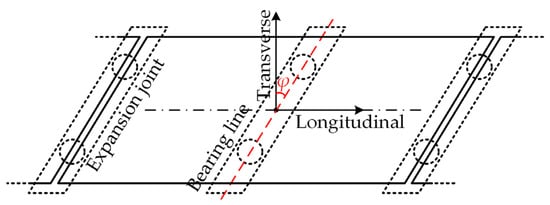
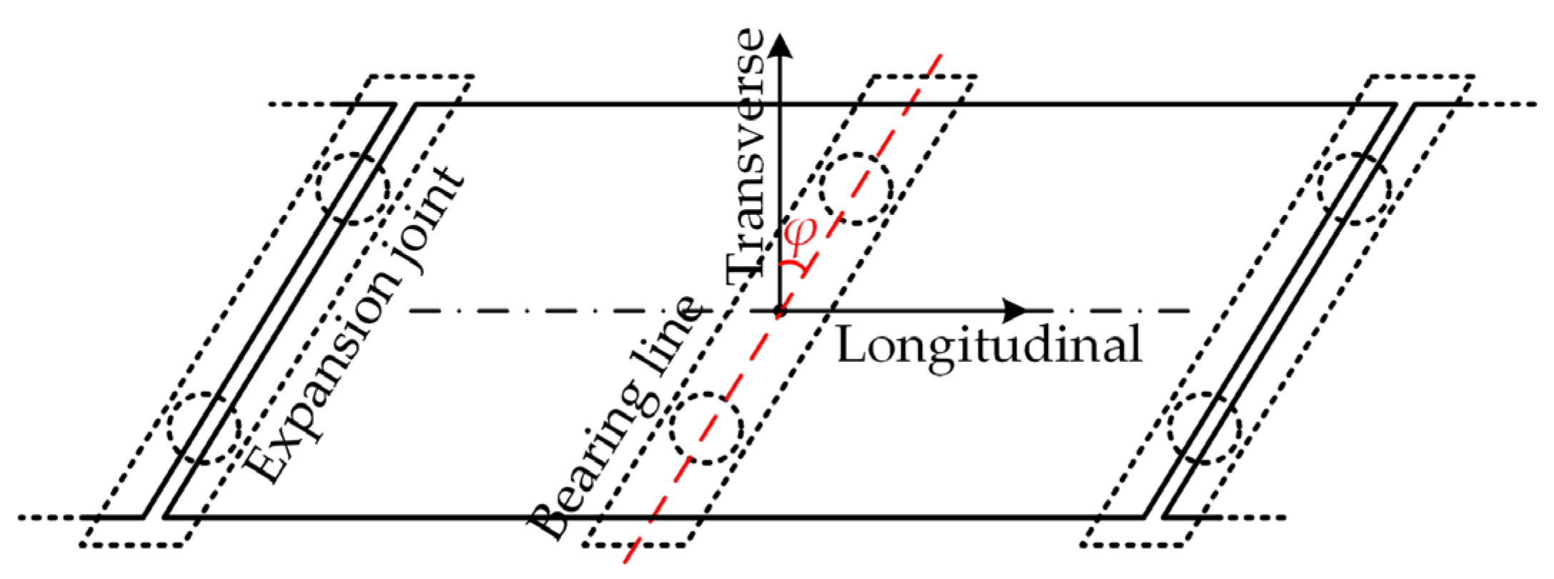
Skewed bridges refer to bridges where the transverse axis of the bearings is not perpendicular to the axis of the route (as shown in Figure 1). The angle (less than 90°) between the longitudinal axis of the bridge and the bearings axis is the skew angle (φ in Figure 1) according to China’s General Specifications for Design of Highway Bridges and Culverts (JTG D60-2015) [39]. Compared with straight bridges, the force condition of skewed bridges will change with different span-to-width ratios, flexural stiffness, torsional stiffness, skew angle, support conditions, and load forms. Specifically, it has the bending–torsion coupling characteristic. This paper takes simply supported reinforced concrete skewed T-girder bridges as the research subject, alongside their most widespread practical applications.
Figure 1.
An overview of the skewed bridge.
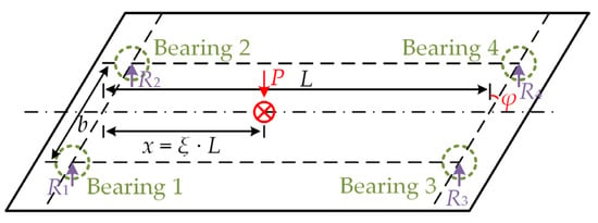
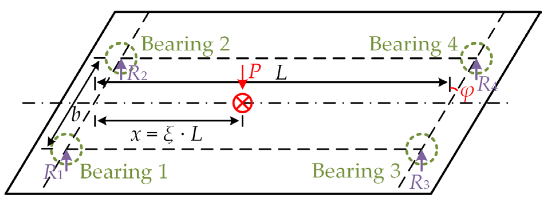
A concentrated vertical force is used to simulate the effect of vehicles on the bridge in order to analyze the transmission of loads within the skewed bridge plane. If a vertical downward load P is applied at the mid-span of the single-span skewed bridge shown in Figure 2. In a simply supported reinforced concrete skewed T-girder bridge, the reaction at a bearing is no longer determined solely by vertical equilibrium. It consists of two superimposed components: the shear component (the same as in a straight bridge, arising from the vertical forces) and the moment component (unique to skewed bridges, the beam experiences torsion while bending because of the skew angle). The torsion must be balanced by a couple formed that is equal in magnitude but opposite in direction, which leads to the reactions at the two bearings at the same end no longer being equal as well as additional bending moment components generated by the torsion. The end moments of the beam can be derived using either the force method or the displacement method. Then, the reactions at bearings one to four (i.e., R1 to R4) are as follows:
where Qa and Qb are the total shear forces at the left and right bearings of the beam, respectively, and Ta and Tb are the moments about the beam axis at the left and right ends of the beam, respectively.
Figure 2.
A mechanical model of the skewed bridge.
Ta and Tb can be calculated as follows:
where k is the ratio of the beam’s flexural stiffness to its torsional stiffness, L is the span of the bridge, and ξ is the relative position of the concentrated load P along the beam, defined as Equation (3).
Substitute Equations (2) and (3) into Equation (1) to obtain the expressions for the bearing forces as follows:
where b is the distance between bearings.
The bending moment M and torque T at the section of interest can be given by the following:
where ξ1 is the ratio of the position x1 of the internal section to the bridge span.
It can be seen that the bending moment and torque are interrelated, which demonstrates the bending–torsion coupling characteristic of skewed bridges. The midspan bending moment of skewed bridges is reduced Tb∙sinφ compared to that of straight bridges according to Equation (5). Due to the influence of the bending–torsion coupling characteristics, the maximum bending moment shifts towards the direction of the obtuse angle connection. The greater the skew angle is, the greater the reduction is in bending moment. According to Equation (2), the greater the ratio of the beam’s flexural stiffness is to its torsional stiffness k, the greater the reduction in bending moment is.
2.2. Refined Numerical Modeling
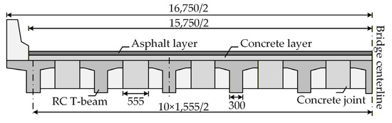
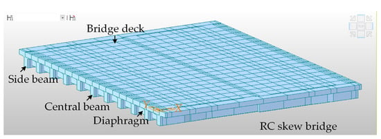
The finite element method was used to analyze a skew beam bridge as an example to verify the above theoretical analysis results and to study the load transfer mechanism of skewed bridges in detail. A skew beam bridge that has been built is shown in Figure 3. It is a 3 × 13 m prestressed reinforced concrete bridge, and the design load is Highway Class I. The bridge is simply supported with a total width of 16.75 m and has a skew angle of 10°. The superstructure is composed of 11 main beams and is supported by a total of 22 plate rubber bearings. The main beam is a T-beam of equal height and prestressed reinforced concrete and is connected by wet joints. Expansion joints are respectively arranged at both sides of the superstructure. C30 is used for concrete, and HRB335 is used for rebar. C30 concrete (characteristic cubic compressive strength fc = 30 MPa) and HRB335 steel reinforcement (yield strength fs = 335 MPa) are adopted.
Figure 3.
The cross-section drawing of the skewed bridge (mm).
The calculation accuracy of the plane beam system element is poor due to the skew angle, and the calculation of the solid element is cumbersome and difficult. The use of the grillage method is a better solution to this problem. The grillage method concentrates the bending moment and torsional stiffness scattered over each plate section in the nearest equivalent grillage. The longitudinal stiffness of the plate is concentrated in the longitudinal grillage, and the transverse stiffness is concentrated in the transverse grillage. It is required that when the actual structure of the prototype and the corresponding equivalent grillage model are subjected to equal loads, their deflection is equal, and the bending moment, shear force, and torque in either grillage are also equal to the internal forces of the actual structure.
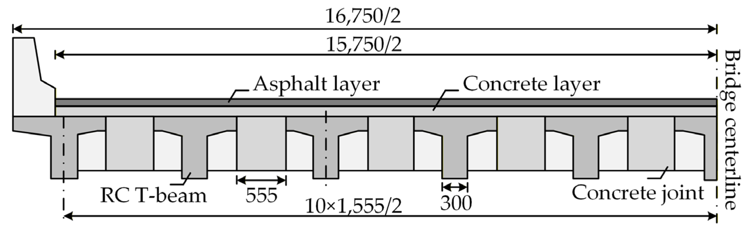
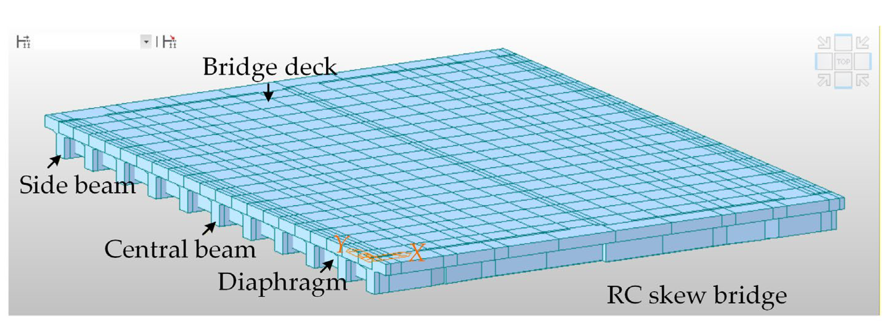
The Midas/Civil 2016 software is used to establish the finite element model of the bridge through the space grillage method, as shown in Figure 4. The Elastic-Beam Column element simulated all girders of the bridge superstructure. All longitudinal girders are connected by the transverse connection system. This system consists of two parts, the actual diaphragm beams and the virtual beams, which are located between the transverse diaphragms. The virtual beam is used to represent the transverse force transfer of the equivalent bridge deck. Its cross-sectional height is taken as 0.18 m (i.e., the thickness of the flange plate), and the moment of inertia is calculated assuming a unit-width rectangular section. The elastic modulus is the same as that of the main girder concrete, and the density is set to zero to avoid double-counting the self-weight. This setup is intended to reasonably reflect the transverse stiffness of the superstructure. The reasonableness of the overall model stiffness has been verified by the on-site static load test results in Section 4.1. The virtual beams are perpendicular to the direction of the girder. By performing trial calculations with various mesh sizes (0.2 to 2.0 m), it was found that the results obtained using a 0.5 m mesh were similar to those with smaller meshes, but the computational cost for smaller meshes was much higher. Larger meshes led to less stable results. Therefore, a fine mesh of 0.5 m is used for the main beams, while a medium mesh of 1.0 m is used for the virtual beams and other parts to better balance computational efficiency and cost.
Figure 4.
The finite-element 3D model of the skewed bridge.
The mechanical behavior of laminated bearings is usually simplified as a linear spring, which is common and sufficient when simulating the static response of bridges. Their stiffness is mainly calculated based on China’s Specifications for Laminated Bearing of Highway Bridge (JT/T 4-2019) [40] and the specific geometric and material parameters of the bearings. In the bearings of the model, the plate rubber bearings were simulated by the Spring element. The bearing nodes are established by copying the corresponding beam element point, which is 0.8 m high from the beam, downward. The spring connection is adopted for the bearing, and the corresponding value is set according to the elastic modulus and shear stiffness of the actual rubber bearing.
2.3. Numerical Simulation Analysis
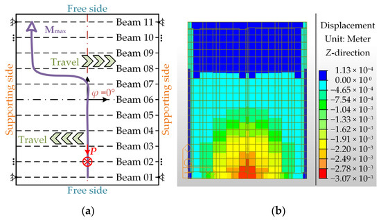
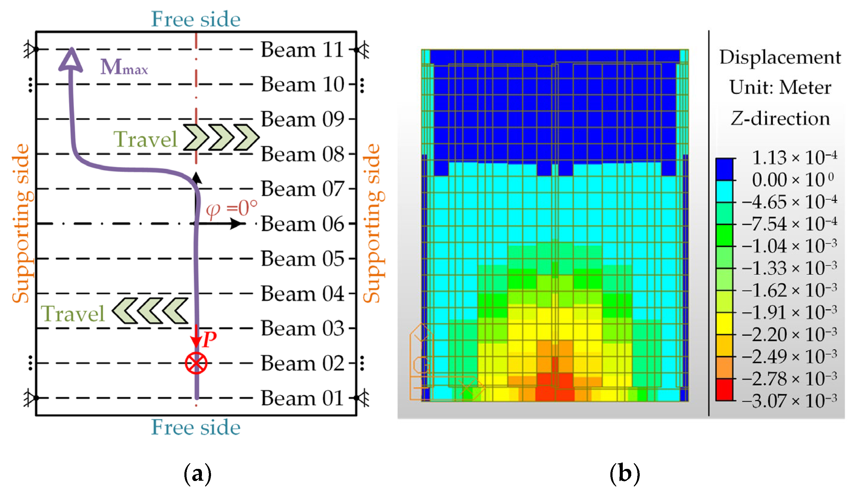
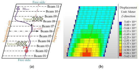
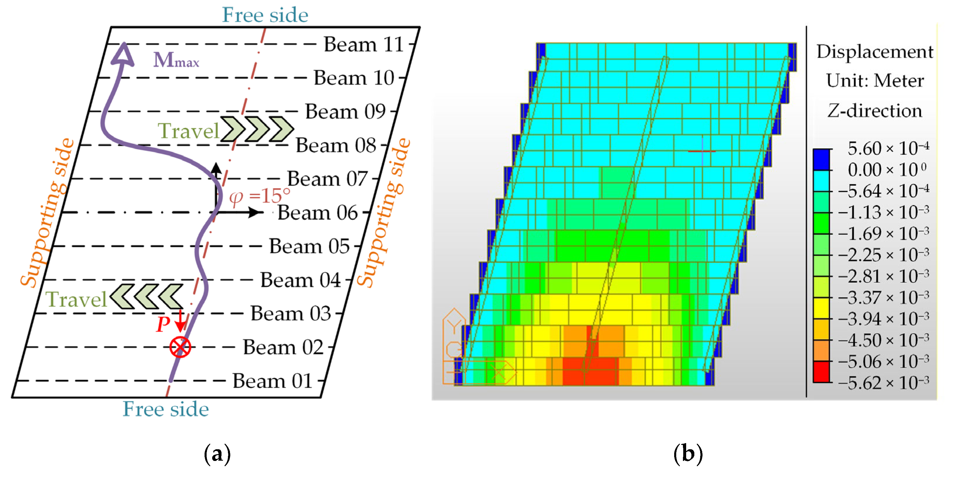
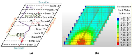
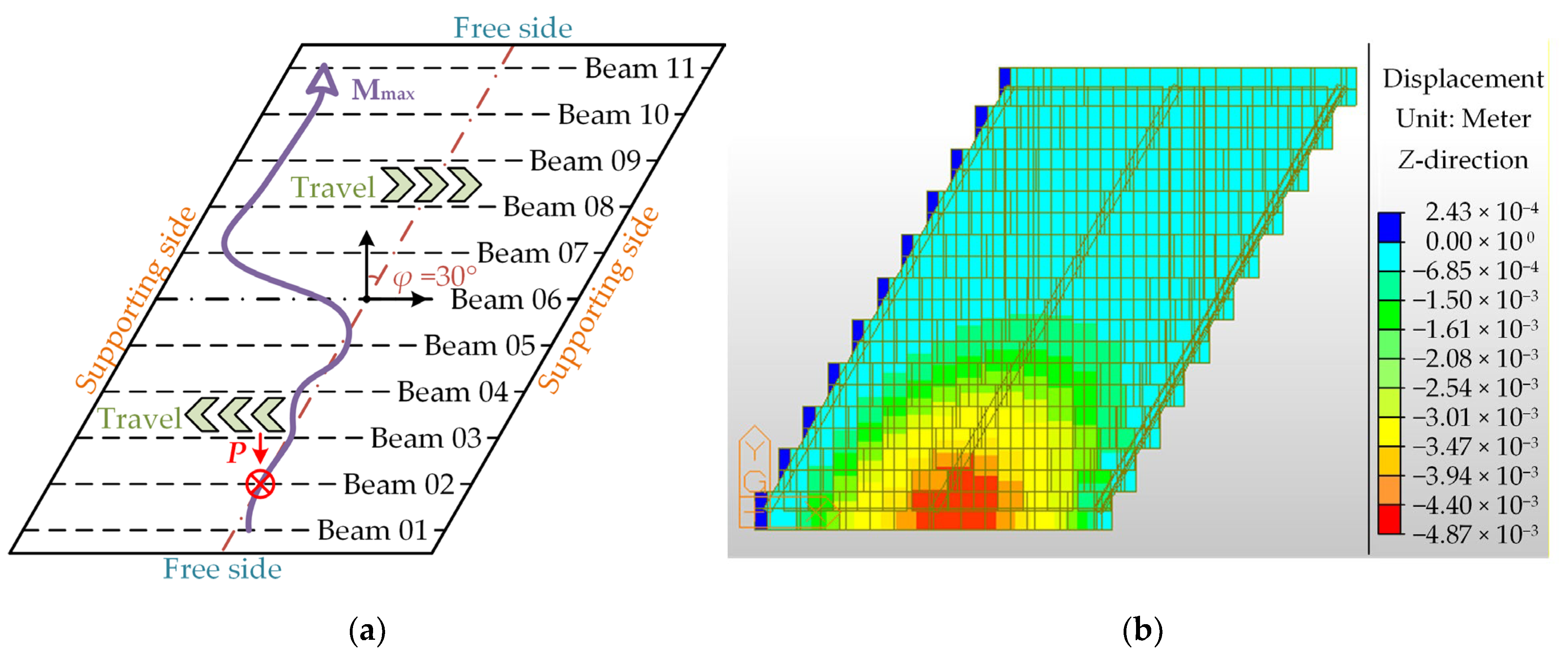
The skew bridge models were established in accordance with China’s Specifications for Design of Highway Reinforced Concrete and Prestressed Concrete Bridges and Culverts (JTG 3362-2018) [38] and China’s General Specifications for Design of Highway Bridges and Culverts (JTG D60-2015) [39]. The bridge models with skew angles of 0°, 15°, 30°, 45°, and 60° were analyzed, and the displacement contours and the direction line of the maximum bending moment transmission were calculated. The load on the bridge was the concentrated load in the middle on the Beam 02. The calculation results of 0°, 15°, and 30° skew angles are shown in Figure 5, Figure 6 and Figure 7, respectively.
Figure 5.
The load transfer trend of the bridge with a 0° skew angle. (a) The maximum bending moment; (b) displacement contours.
Figure 6.
The load transfer trend of the bridge with a 15° skew angle. (a) The maximum bending moment; (b) displacement contours.
Figure 7.
The load transfer trend of the bridge with a 30° skew angle. (a) The maximum bending moment; (b) displacement contours.
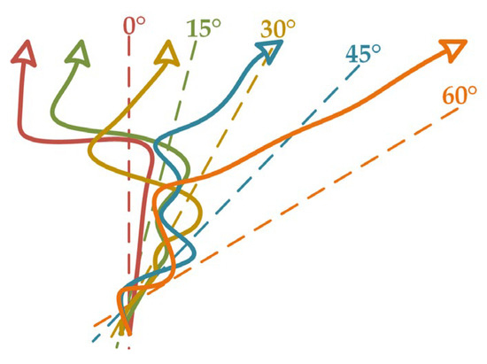
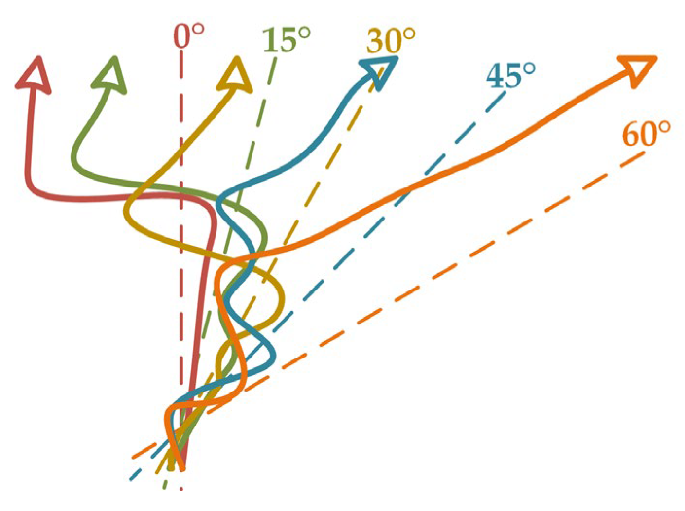
The load transfer path is the line connecting the points of maximum bending moment of each beam in the skewed bridge under the point load, passing through the load point. This path indicates the load response of the transverse of a skew bridge; the greater the skew angle is, the more impeded the load transfer is. The load transfer trends of the various skewed bridges are summarized and compared in Figure 8. It can be seen that unlike the straight bridge, the line of the maximum bending moment of the skew beam bridge is first transmitted along the connecting line in the middle of each beam span and then begins to develop in the direction of the free side (obtuse angle). As the skew angle increases, the trend towards the free edge appears earlier. The degree of separation between the transverse transmission line of the maximum bending moment in the span and the connecting line in the middle of each beam increases with the increase in skew angle.
Figure 8.
A comparison of the load transfer trend of skewed bridges with different skew angles.
According to theoretical analyses, the bending–torsion coupling effect of skew bridges as well as the resulting moment reduction and internal force redistribution mainly depend on key parameters such as the ratio of the beam’s flexural stiffness to its torsional stiffness k, which reflects the section characteristics, and the span-to-width ratio (L/B), which reflects the overall geometric configuration. To refine the theoretical framework, we briefly explain the effects of these two parameters based on the above models. The larger the k value is, the more significant the bending–torsion coupling effect is, manifested as an increased reduction in mid-span bending moments and a tendency for the load transfer path to shift earlier and more noticeably toward the obtuse-angle side. This is because a larger k value means that torsional deformation occurs more easily, exacerbating the redistribution of internal forces. The smaller the span-width ratio is, the more pronounced the transverse load transfer effect is. For wide bridges, the moment reduction effect is weaker, but the uneven distribution of bearing reactions is more prominent. The load transfer path exhibits a more complex two-dimensional diffusion pattern in wide skew bridges.
These characteristics have a certain influence on the bearing reaction forces and mid-span bending moments of skewed bridges. It is necessary to propose a simplified design method on the basis of computer-aided fine modeling and optimization design so as to facilitate the use of engineering personnel.
3. Design Method of Mixed Influence Line
3.1. Load Distribution Theory
When load P is applied on the bridge, due to the transverse rigidity of the superstructure, the load will inevitably be transferred in the x and y directions simultaneously, and all the main beams will participate in the work to varying degrees. The basic philosophy of the transverse distribution coefficient calculation method is to transform the spatial problem into a plane problem for solving. The essence of this method is to separate the influence surface function η(x,y) into the product of two single-valued functions. Therefore, the value of the internal force for a certain section of a girder can be expressed as follows:
where η1(x) is the longitudinal internal force influence line of a certain section of a single beam and η2(y) is the influence line of the load transverse distribution for a beam.
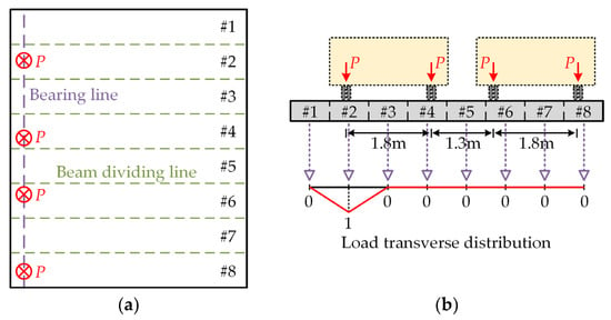
The formation of Equation (6) is to decompose the complex calculation of spatial forces into two relatively independent and easier-to-solve steps: ‘longitudinal conduction’ and ‘transverse distribution.’ The core task of the transverse distribution theory is to find an accurate and simple method to determine η2(y) for bridges. For straight bridges, when the load acts on the bearing line, the bearing shear force under live load can be calculated using the LPM; that is, the wheels on other beams do not affect the force of the bearing beam. Hence, the transverse load distribution influence line (TLDIL) can be simply obtained by identifying whether there is a vehicle load on the beam of interest. The load transverse distribution of this method is shown in Figure 9. The TLDIL does not represent the bending moment or shear force distribution of the longitudinal beams but is used to describe the distribution ratio of vehicle loads among the transverse main beams. In Figure 9b, the influence line is calculated using the LPM, and its vertical coordinate represents the proportion of the load borne by the target beam when a unit load is applied at a certain position on the beam. When the load is applied near the bearing, the lateral load transfer path is approximately hinge joint distributed, so the load distribution coefficients of each beam can be quickly determined by this method. Taking Beam #2 as an example, the wheels acting on Beam #4, Beam #6, and Beam #8 will not affect the influence line of the wheels on Beam #2.
Figure 9.
Load distribution and calculation method for straight bridges. (a) Load distribution; (b) lever principal method.
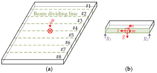
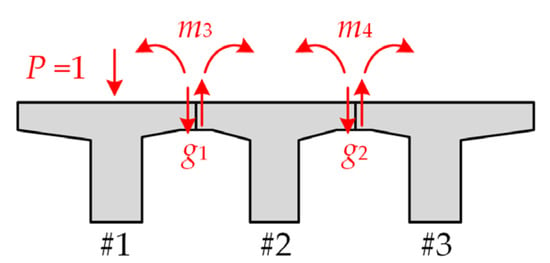
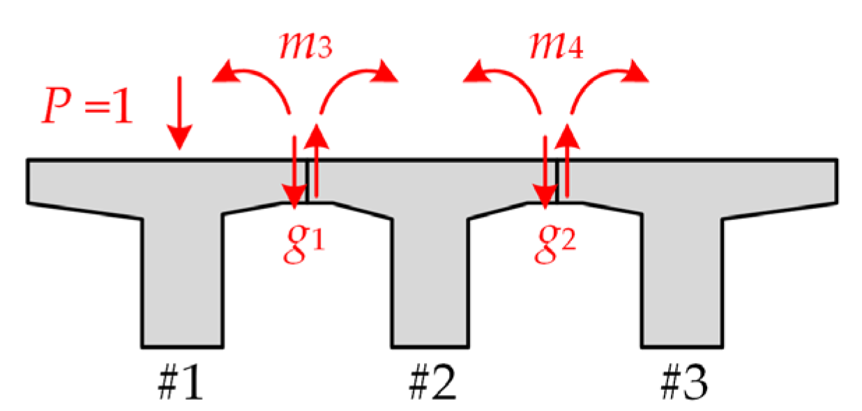
When the load acts outside the bearing line, the bearing shear force under a live load can be calculated using the RPGM; that is, the wheels on other beams affect the force of the bearing beam. This is due to the fact that the internal forces experienced by the joints between the plate girders are responsible for the transfer of loads. In general, the internal forces that can be caused on the joint are the vertical shear force g, the transverse bending moment m, the longitudinal shear force t, and the normal force n, as shown in Figure 10. However, when the vertical wheel load is mainly applied on the bridge, the longitudinal shear force and normal force have little effect compared with the vertical shear force.
Figure 10.
A force diagram of the superstructure. (a) The loading of the superstructure; (b) individual beam analysis.
For a bridge composed of n beams with n − 1 joints, if the slab girder is cut along the joint, a pair of sinusoidal shear force gi and transverse moment mi with equal magnitude and opposite direction is acted on in each joint. Therefore, for n plate beams, there are n − 1 desired peak shear forces gi. If all the shear forces are obtained, the vertical load distributed to each plate can be obtained according to the principle of force equilibrium. Obviously, for the super statically determined problem with n − 1 unknown vertical shear forces, there are always n − 1 joints, and each joint can be cut to form a basic system. All the vertical shear peaks can be solved by using the deformation coordination condition that the vertical relative displacement and rotation angle are zero between the two adjacent plates at the joints. The deformation coordination equation is
where δik is the vertical displacement at the joint i caused by the sinusoidal joint force in the joint k and δiP is the vertical displacement at the joint i caused by the external load P.
Equation (7) is derived based on the deformation compatibility conditions and the superposition principle in structural mechanics. Its physical significance is that after virtually cutting the bridge deck along the longitudinal joints, the vertical relative displacement and relative rotation of each beam at the joints should be zero to satisfy the actual structural continuity conditions. Taking Figure 11 as an example, the RPGM is applied, and the following equations can be listed.
Figure 11.
A computational diagram of the rigid plate girder method.
As long as all the vertical shear peak values gi are solved, the peak vertical load Pi and the load distribution can be obtained for each beam according to the force balance principle. When a unit load acts on any plate girder, the load assigned by the Beam #1 can determine the vertical scale value η1 of the transverse influence line of the Beam #1. As long as each ηi is depicted in proportion to the axis position of the corresponding plate girder and then connected by a smooth curve, the transverse distribution influence line and load transverse distribution coefficient of the Beam #1 are obtained. The calculation method for other beams is the same.
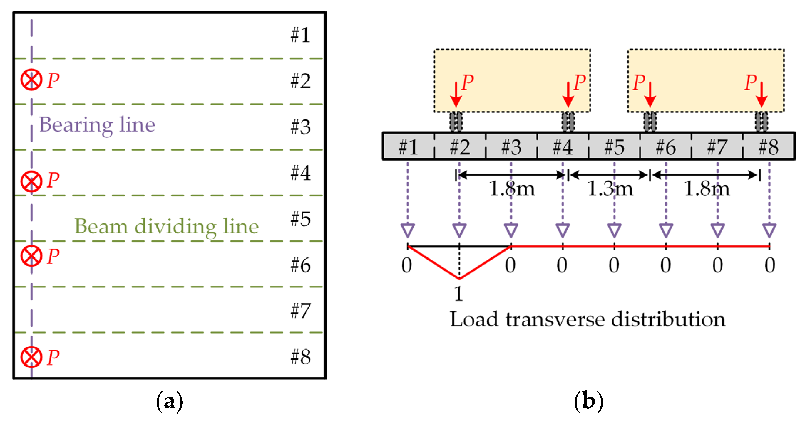
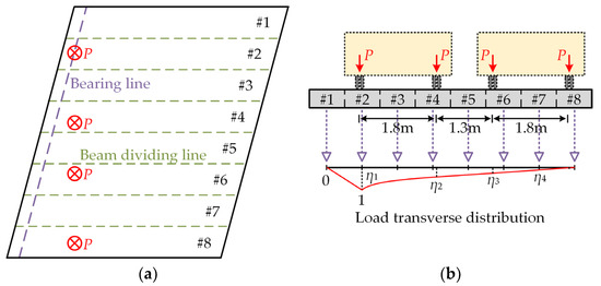
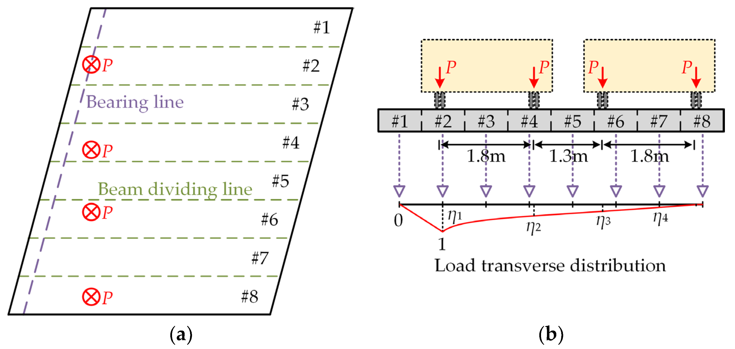
However, the load distribution in skewed bridges is more complex. For skewed bridges, η2(y) is not a fixed value but varies with the position of the load x along the span of the bridge. The mixed influence line method proposed in this paper is based on the mechanism of integrating two classical transverse distribution theories according to the position of the load, allowing for an efficient approximation of the complex spatial influence surface η(x,y) of skewed bridges. As shown in Figure 12a, taking Beam #2 as an example, the wheels acting on Beam #4, Beam #6, and Beam #8 will have an elastic distribution effect on the influence line of the wheels on Beam #2. The LPM can be used only for the calculation of loads acting at the bearings, while for loads not acting at the bearings, the lateral stiffness of the bridge should be fully considered to reasonably distribute loads to the surrounding beams. Therefore, the hybrid influence line method can be used to calculate the bearing forces caused by loads not acting at the bearings.
Figure 12.
Load distribution and calculation method for skewed bridges. (a) Load distribution; (b) mixed influence line method.
Considering that the transverse stiffness of the skewed bridge is large, the loads not acting at the bearings distributed by the rigid plate girder method and the corresponding influence line coordinates can be obtained. It can be assumed that the transverse distribution of the load is taken in the direction perpendicular to the free side from the load transfer mechanism in the above section. According to the action position of the load on the beam, the middle section of the straight bridge can be taken correspondingly, or the transverse distribution coefficient can be interpolated along the variation section of the bridge span to obtain the coordinates of the TLDIL. This method of calculating the TLDIL is the mixed influence line method (MILM), as shown in Figure 12b. The TLDIL shown in Figure 12b reflects the distribution characteristics of a skew bridge under vehicle load. This influence line is drawn based on the MILM, which combines the principles of the LPM and the RPGM to account for the bending–torsion coupling effect and variations in transverse stiffness caused by the skew angle. The curves represent the variation trend of the transverse load distribution coefficients at different longitudinal positions (such as the bearing and mid-span), rather than the longitudinal distribution of internal forces (bending moments and shear forces) within the beam. Theoretically, the MILM has changed the mechanical meaning of the TLDIL; that is, the sum of the longitudinal marks of the influence line is one, but its physical meaning is clear, reflecting the characteristics of the skewed bridge’s transverse load distribution.
3.2. Calculation Method and Flow
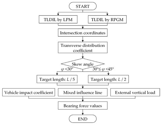
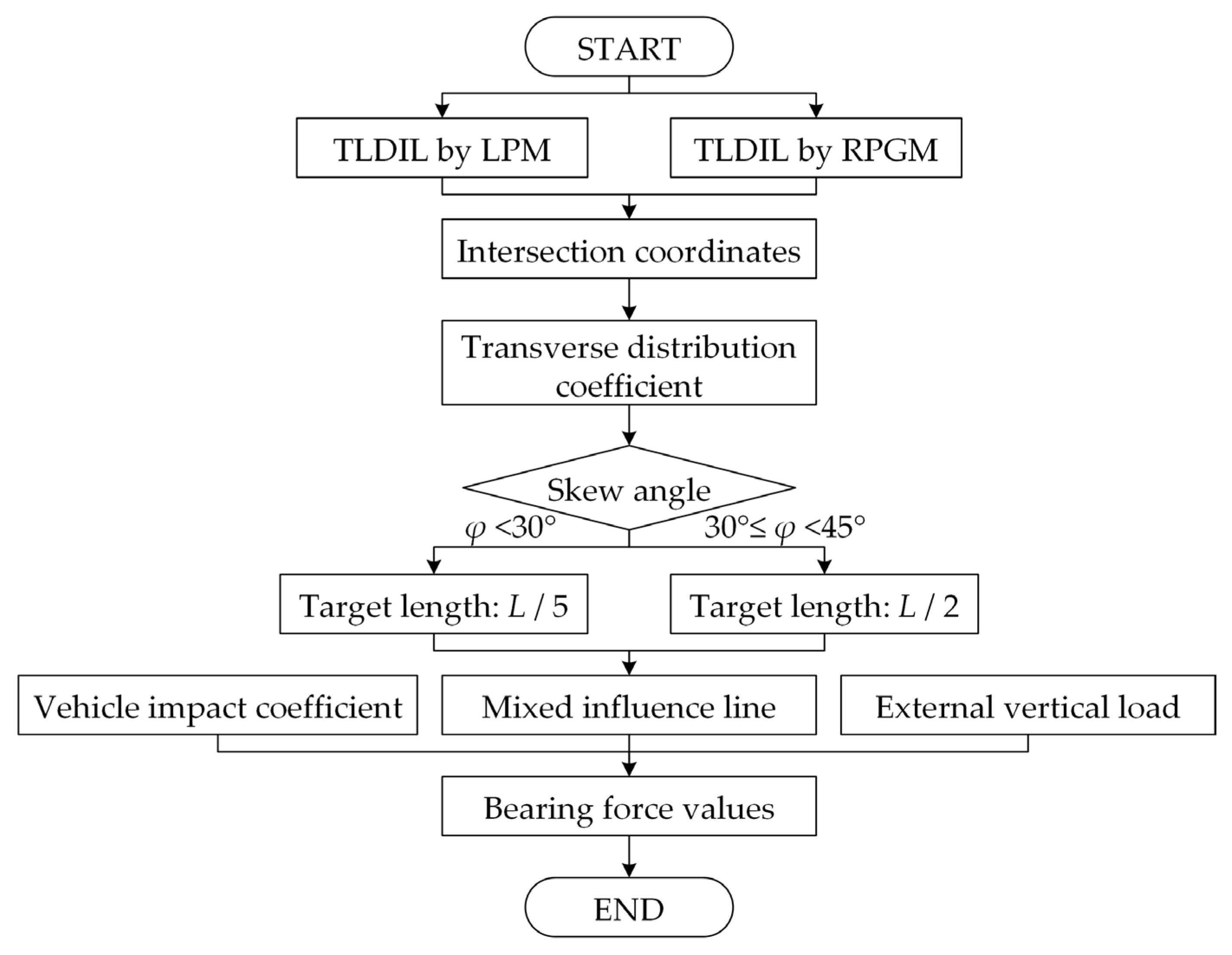
Specifically, the following steps are proposed to calculate the bearing force of a skew beam bridge. The first four are (1) drawing the TLDIL of the bridge without taking into account the skew angle by the lever principal method, (2) drawing the TLDIL of the bridge without taking into account the skew angle by the rigid plate girder method, (3) obtaining the intersection point with the result of steps (1) and (2), and (4) considering the transition of the transverse distribution coefficient along the bridge span and drawing the mixed influence line. The length of the transition section is related to the skew angle according to the load transfer mechanism of the skewed bridge. When the φ < 30°, L/5 can be taken as the target length and when 30° < φ < 45°, L/2 can be taken as the target length according to the numerical values and experimental results, (5) the bearing’s force of the bridge can be obtained by multiplying the mixed influence line and external vertical load values; (6) the impact coefficient μ needs to be considered for vehicle loads.
The above calculation steps of the mixed influence line method are summarized in Figure 13. The bearing’s force results calculated by the proposed method consider the two influencing factors of the bridge skew angle and lateral stiffness, which is more consistent with the actual structural stress state of the simply supported skew beam bridge.
Figure 13.
The calculation flow of the proposed method.
4. Validation and Analysis
4.1. Experimental Validation
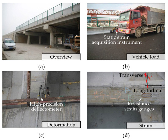
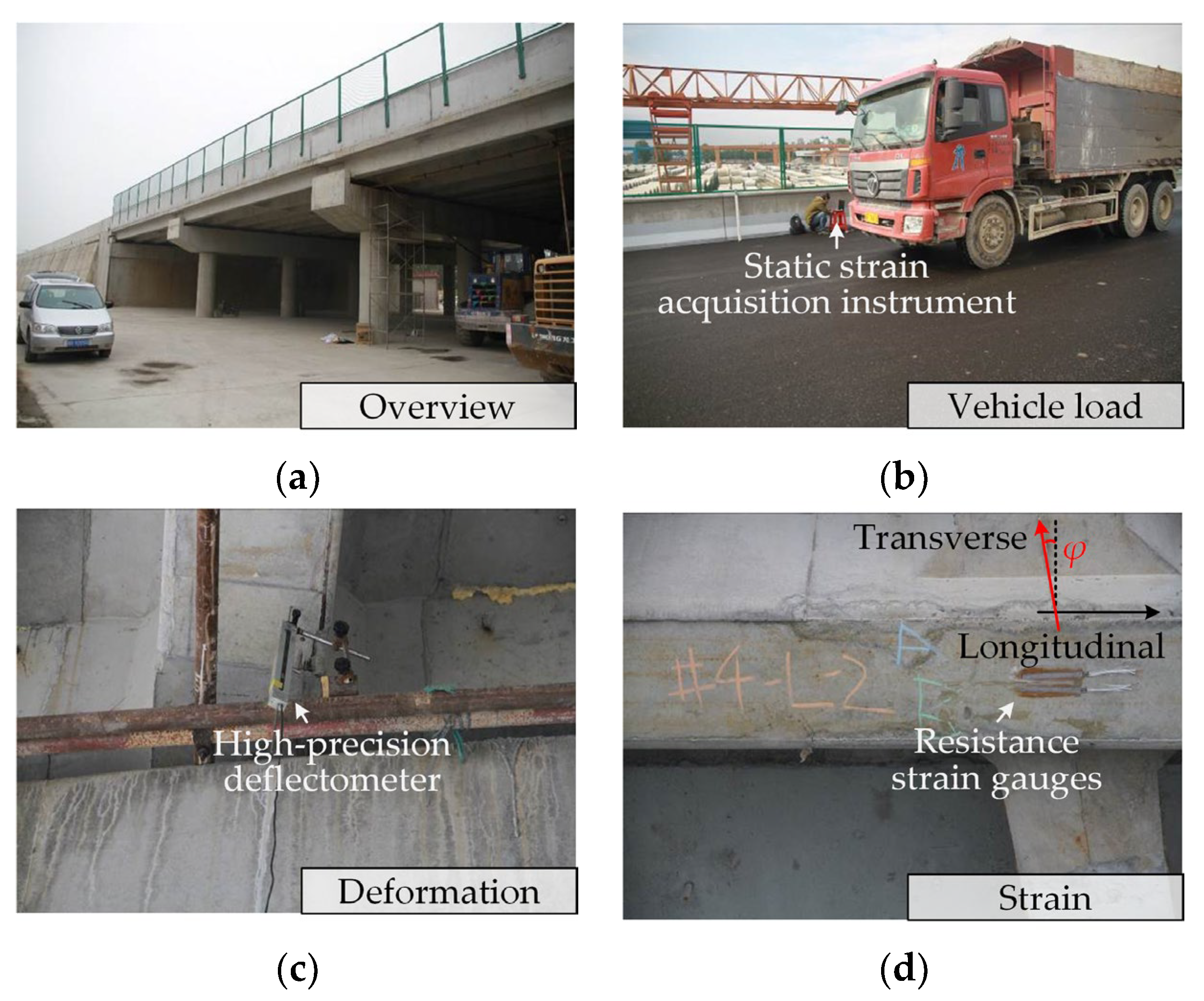
The research subject of this paper was the simply supported reinforced concrete skewed T-girder bridges. To confirm the accuracy of the above-mentioned finite element model and the proposed calculation method, the field static load test was carried out on the skewed bridge shown in Figure 3. Three standard vehicles weighing 450 kN (denoted as VA, VB, and VC, respectively) applied the load. The test consisted of six working conditions, which mainly measured the deformation and strain of the bridge under vehicle loads. For the displacement measurement scheme, we installed a high-precision deflectometer at the mid-span of the beam bottom and used a total station to check the overall deformation. For the strain measurement scheme, we arranged resistance strain gauges at the mid-span and bearings of the key beam bottom and used a static strain acquisition instrument to record the strain values. For the bearing force measurement scheme, we installed pressure sensors at the plate-type rubber bearings to monitor the distribution of bearing force reactions in real time.
The test conditions are summarized as follows. Condition 1: The side wheel of the rear axle of VA acts on the side span of Beam #2. Condition 2: The side wheel of the middle axle of VA acts on the side span of Beam #2. Condition 3: The side wheel of the middle axle of VA acts on the middle span of Beam #2. Condition 4: The side wheel of the rear axle of VA acts on the side span of Beam #2, and VB and VC are arranged in turn. Condition 5: The side wheel of the middle axle of VA acts on the side span of Beam #2, and VB and VC are arranged in turn. Condition 6: The side wheel of the rear axle of VA acts on the middle span of Beam #2, and VB and VC are arranged in turn. Condition 7: The side wheel of the rear axle of VB acts on the bearing of Beam #6, and VC is arranged in turn. The details of the test are shown in Figure 14. The bridge in this test belonged to the category of small-angle skew bridges, and its mechanical behavior differed from that of large-angle skew bridges. Therefore, the results of this experiment were used to verify the reliability of the modeling process and methodology system and are not to be taken as direct evidence that this method applies to large-angle skew bridges.
Figure 14.
The field static load test. (a) An overview of the bridge; (b) vehicle load; (c) the deformation measurement; (d) the strain measurement.
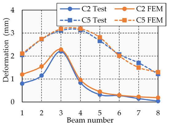
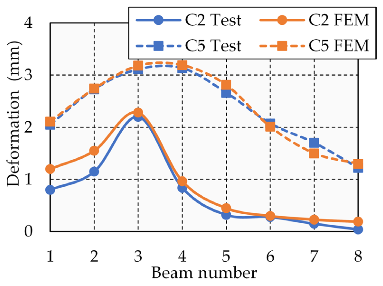
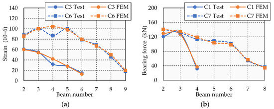
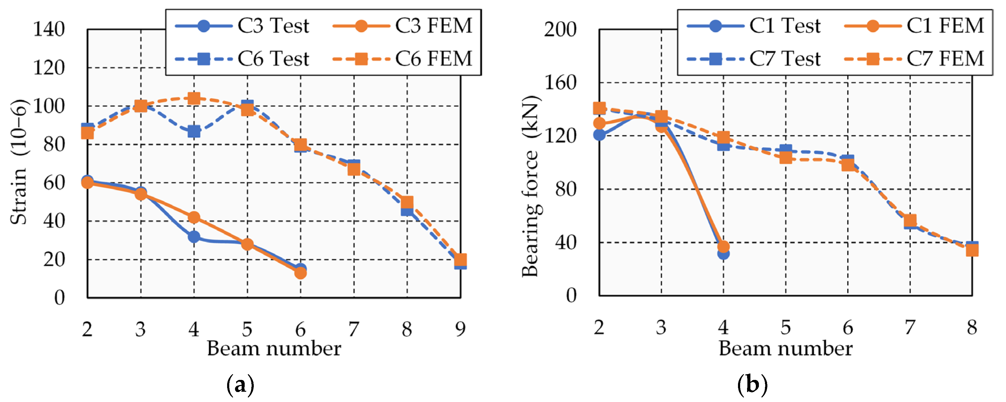
To systematically verify the reliability of the finite element model, comparisons were made from three aspects: displacement, strain, and bearing force. Displacement verification: The measured and finite element calculated mid-span deflections at the bottom of the beam under each condition (Condition 2 and Condition 5) were compared, and the results are shown in Figure 15. Strain verification: The strain distribution at the bottom of the mid-span section of the beam was compared (Condition 3 and Condition 6), and the results are shown in Figure 16a. Bearing force verification: The finite element results were compared with the measured reactions (Condition 1 and Condition 7), as shown in Figure 16b. The beam displacement results for Condition 2 and Condition 5 are shown in Figure 15. Under the action of single-row eccentric load (Condition 2), the results of the finite element method were larger for Beams #1 and #2. It is because the distance of the vehicle load from the center line of the bridge was 6.3 m in the finite element model, and the influence of eccentric moment on Beams #1 and #2 caused the assigned load to be larger. In the actual bridge engineering, the anchor reinforcement of the guardrail is welded with the stirrups of Beam #1, and the solid cross-sectional size of the guardrail is twice that of the beam, so the measured value is smaller due to the increase in stiffness. The calculation and test results of other beams are in good agreement. Under the action of a three-row eccentric load (Condition 5), the average error between the calculated beam bottom displacement and the test results is less than 6%. In addition, the model of the transverse transfer law of the load is also in good agreement with the measured results. The specific results are summarized in Table 1.
Figure 15.
Results of beam displacement.
Figure 16.
Results of strain and bearing force. (a) Strain at beam bottom; (b) bearing force.
Table 1.
Comparison of results by Test and FEM.
The strain results at beam bottom for Condition 3 and Condition 6 are shown in Figure 16a. Under the action of single-row eccentric load (Condition 2) and three-row eccentric load (Condition 4), only the calculated value of the mid-span strain in Beam #4 was slightly larger than the measured value, and the others were in good agreement. In fact, due to the constraints of the bearings at the two ends, the actual force of the middle span should be closer to the calculation results of the model. The bearing force results for Condition 1 and Condition 7 are shown in Figure 16b. It can be seen that the calculated values are in good agreement with the experimental values, and the average relative error is less than 5%.
In general, the finite element model adopted in this paper was effectively verified by a series of static vehicle loading tests on a skew beam bridge. The experimental results of the bearing force were particularly in good agreement with the calculation results, which verified the correctness of the proposed model and calculation method. The load transverse transfer tend of the bridge was also in good agreement with the theoretical analysis. In addition, it is worth noting that for bridges with large width-span ratios, the influence of bridge guardrails on the stiffness of side beams cannot be ignored. The measured displacement of the side and secondary side beam may be less than the calculated displacement of the model.
4.2. Numerical Analysis
Based on the comparison between the experimental results and the finite element results, the applicability of the proposed theory and the accuracy of the model is illustrated. However, due to the small skew angle of the bridge in the test, it is difficult to comprehensively compare the accuracy of the proposed calculation method and explain the special mechanical properties of the skewed bridge. Therefore, a large number of skew beam bridges were analyzed and compared with the proposed calculation method and finite element method by modifying the skew angle of the finite element model.
Calculations for a bridge were carried out first based on the structure shown in Figure 3. The bearings’ force (excluding impact force) of Beam #1 to #6 of the skewed bridge with angle 30° under the Highway-I Class load was calculated by the finite element method and the mixed influence line method. The calculation results are compared in Table 2. It can be seen that the relative errors between the mixed influence line method and the finite element method were 3.4% to 5.8%. The result value calculated by the mixed influence line method was larger, which indicated that the proposed method met the accuracy requirements and was safer.
Table 2.
Comparison of calculation results by FEM and MILM.
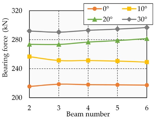
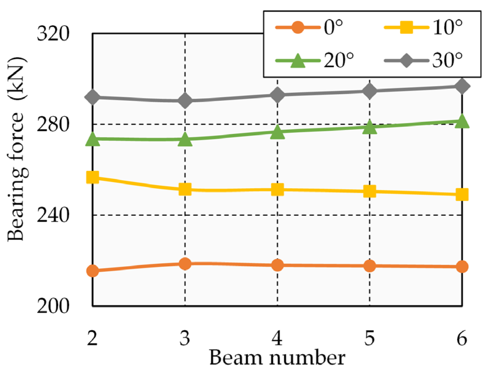
The bearing force results for the skewed bridge with different angles were calculated, as shown in Figure 17. It can be seen that the larger the angle was, the more the ratio of the bearing forces of the skewed bridge to the straight bridge increased from 1.15 times to 1.35 times. The force growth rate of each beam was less than 5%. The increase in bearing forces was based on the skew bridge shown in Figure 3 and was obtained through parametric analysis by varying the skew angle. The primary purpose of this quantified relationship was to reveal the significant influence and basic rules of the skew angle. When applying this conclusion to actual engineering projects, attention should be paid to their dependence on parameters such as span-to-width ratio and load type. For bridges with significantly different parameters, it is recommended to perform specific calculations based on the methods in this paper or to conduct parametric analysis.
Figure 17.
Bearing forces of skewed bridges with different angles.
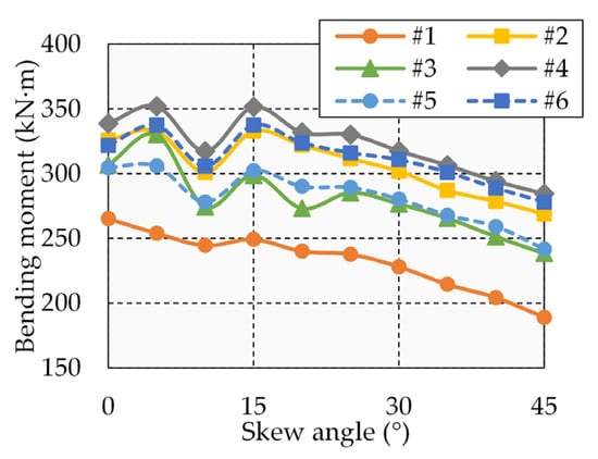
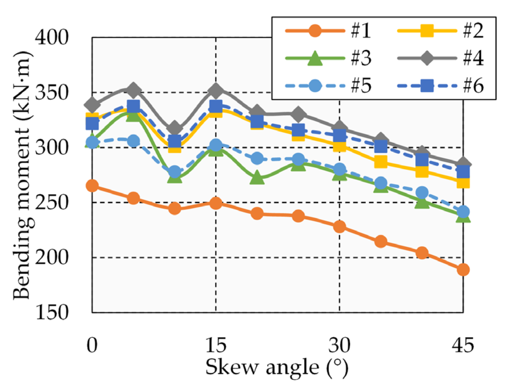
Figure 18 shows the mid-span bending moments of the obtained beam and their variation with the skew angles according to the transverse load arrangement of the mixed influence line under the Highway-I class load. It can be seen that the bending moment decreased with the increase in skew angles. Beam #1 was the obtuse corner beam, which is the critical design element for skewed bridges. The bending moment of this beam was minimal, and it decreased rapidly as the skew angle increased. According to the mechanical characteristics of the skew beam bridge in Second 2, the reduction value of the mid-span bending moment was Tb∙sinφ. The eccentricity of the side beam (Beam #1) and the center line of the bridge due to the load arrangement was greater than that of the middle beam (Beam #6). The torque Tb of the side beam generated by the load was greater than that of the middle beam, and the reduction of the bending moment in the middle span was greater than that of the middle beam. Therefore, in the case of a same span, the wider the bridge was, the greater the influence of torque Tb was, and the greater the reduction of the bending moment in the side beam was. In addition, regardless of the side or the center beam, the mid-span bending moment decreased with the increase in sinφ.
Figure 18.
The bending moment in the middle of skewed bridges with different angles.
The ratio of the mid-span bending moments in the skewed bridge to the straight bridge are summarized in Table 3. It can be seen that when the skew angle is less than 30°, the mid-span bending moment of the skewed bridge is more than 0.9 times that of the straight bridge, so its design bending moment can be approximated to take the moment value of the straight bridge. However, when the skew angle is 30° to 45°, the mid-span bending moment of the skewed bridge will be significantly reduced compared with the straight bridge, so the reduction coefficient can be safely taken as 0.85 to 0.95 in the design. In addition, considering Equations (2) and (5), it can be seen that when the concentrated force acts on the centerline of the bridge, the torque Tb is proportional to the span L. In the case of a same skew angle, the reduction coefficient of the mid-span moment is proportional to the span L. Taking the 40° skew bridge as an example in Table 3, its average midspan bending moment is about 0.84 times that of a straight bridge. Hence, the skew bridge can reduce the bending moment design value by theoretically 15%. According to the approximate proportional relationship between the amount of reinforcement and the bending moment in a reinforced concrete bending member, the required longitudinal reinforcement area can also be reduced by about 15%. It not only directly reduces the amount of steel and construction cost but also simplifies the reinforcement arrangement.
Table 3.
The ratio of the mid-span bending moments in the skewed bridge to the straight bridge.
5. Conclusions
This study integrates theoretical analysis, numerical simulation, and field experiments to systematically investigate the load transfer mechanism of skewed T-girder bridges and proposes a simplified design method based on a mixed influence line. The proposed method is theoretically clear, with a well-defined process, making it convenient for engineering applications. The main conclusions are as follows.
- (1)
- Load transfer mechanism: The path of the load transverse distribution of the skew beam bridge tends to develop perpendicular to the direction of the free side. The beam with this trend is closer to the beam of the load direct action with the increase in the skew angle. This spatial transfer characteristic reflects the bending–torsion coupling behavior of skew bridges.
- (2)
- Innovation in design methods: A mixed influence line method was proposed for calculating the bearing force of the skew beam bridge, which combines the lever principal method and the rigid plate girder method. The corresponding computer principles and steps are given in detail. According to the theoretical and finite element comparison results, the calculation results meet the design requirements and are safe.
- (3)
- Key quantitative indicators: (a) For the skewed T-girder bridges, the bearing force caused by the vehicle load increases with the increase in the angle. When the skew angle is 30°, the support reaction is approximately 1.35 times that of a straight bridge. Its specific value varies with parameters such as the bridge’s span-to-width ratio and load type. (b) The mid-span bending moment decreases as the skew angle increases, with the reduction depending on the bridge width, span, and load position. When the skew angle is less than 30°, the mid-span bending moment can be approximated by the value for a straight bridge; when the skew angle is between 30° and 45°, it is recommended to use a bending moment reduction factor of 0.85 to 0.95.
- (4)
- Engineering suggestions: It is recommended to use the mixed influence line method proposed in this paper for load transverse distribution calculations in skew bridge design. This is especially important for bridges with larger skew angles (>30°), where directly applying the calculation methods for straight bridges should be avoided to prevent underestimating the bearing’s force and shear force demands.
Author Contributions
Methodology, F.S.; validation, J.L.; writing—original draft preparation, J.L.; writing—review and editing, F.S.; visualization, Z.D. and Y.Z.; funding acquisition, F.S. All authors have read and agreed to the published version of the manuscript.
Funding
This research study was funded by the Research Project of Zhejiang Provincial Education Department, grant number Y202456759, and the Student Innovation and Entrepreneurship Training Program at Zhejiang University of Water Resources and Electric Power, grant number 202511481015.
Data Availability Statement
The original contributions presented in this study are included in the article. Further inquiries can be directed to the corresponding author.
Conflicts of Interest
The authors declare no conflicts of interest.
References
- Asadi, M.; Kilanehei, F.; Mahjoob, A. Numerical Study of Road Embankment Type Action on Shear Stress Around Skewed Bridge Abutment. Balt. J. Road Bridge Eng. 2022, 17, 95–119. [Google Scholar] [CrossRef] [Scilit]
- Agarwal, P.; Pal, P.; Mehta, P.K. Parametric study on skew-curved RC box-girder bridges. Structures 2020, 28, 380–388. [Google Scholar] [CrossRef] [Scilit]
- Shi, Y.; Wang, J.; Han, J.; Qin, H.; Che, C. Direct displacement-based design of skewed bridge isolated with LRBs. Structures 2024, 66, 106912. [Google Scholar] [CrossRef] [Scilit]
- Lu, R.; Judd, J.; Barker, M. Field Load Rating and Grillage Analysis Method for Skewed Steel Girder Highway Bridges. J. Bridge Eng. 2021, 26, 05021013. [Google Scholar] [CrossRef] [Scilit]
- Du, H.; Xu, L.; Deng, H.; Lu, X. In-plane rotation response of skewed simply supported bridges considering multi-point pounding effect. Structures 2024, 70, 107813. [Google Scholar] [CrossRef] [Scilit]
- McConnell, J.; Radovic, M.; Keller, P. Holistic finite element analysis to evaluate influence of cross-frames in skewed steel I-girder bridges. Eng. Struct. 2020, 213, 110556. [Google Scholar] [CrossRef] [Scilit]
- Lou, L.; Zerva, A. Effects of spatially variable ground motions on the seismic response of a skewed, multi-span, RC highway bridge. Soil Dyn. Earthq. Eng. 2005, 25, 729–740. [Google Scholar] [CrossRef] [Scilit]
- Huang, Y.; Xu, Y.; Ji, J. Analysis of Rational Finite Element Model of Two-Span Skew Girder Bridge Based on Shaking Table Test. Adv. Civ. Eng. 2022, 2022, 9446398. [Google Scholar] [CrossRef] [Scilit]
- Liu, X.; Guo, W.; Li, J.; Zhang, H.; Baraldi, D. Seismic Study of Skew Bridge Supported on Laminated-Rubber Bearings. Adv. Civ. Eng. 2020, 2020, 8899693. [Google Scholar] [CrossRef] [Scilit]
- Mangalathu, S.; Heo, G.; Jeon, J.-S. Artificial neural network based multi-dimensional fragility development of skewed concrete bridge classes. Eng. Struct. 2018, 162, 166–176. [Google Scholar] [CrossRef] [Scilit]
- Aldea, S.; Bazaez, R.; Astroza, R.; Hernandez, F. Seismic fragility assessment of Chilean skewed highway bridges. Eng. Struct. 2021, 249, 113300. [Google Scholar] [CrossRef] [Scilit]
- Wilson, T.; Chen, S.; Mahmoud, H. Analytical case study on the seismic performance of a curved and skewed reinforced concrete bridge under vertical ground motion. Eng. Struct. 2015, 100, 128–136. [Google Scholar] [CrossRef] [Scilit]
- Kaviani, P.; Zareian, F.; Taciroglu, E. Seismic behavior of reinforced concrete bridges with skew-angled seat-type abutments. Eng. Struct. 2012, 45, 137–150. [Google Scholar] [CrossRef] [Scilit]
- Dimitrakopoulos, E.G. Analysis of a frictional oblique impact observed in skew bridges. Nonlinear Dyn. 2009, 60, 575–595. [Google Scholar] [CrossRef] [Scilit]
- Wu, S.; Buckle, I.G. Effect of skew on the minimum support length requirements of single-span bridges with seat-type abutments. Earthq. Spectra 2020, 36, 1119–1140. [Google Scholar] [CrossRef] [Scilit]
- Wu, S.; Huang, J.; Li, W.; Jiao, C.; Li, J. Unseating of single-span bridges with skew angles out of the limit range for free rotation. Structures 2021, 32, 1320–1330. [Google Scholar] [CrossRef] [Scilit]
- Gupta, T.; Sandhu, D. Seismic response of horizontally curved bridges in combination with skewed abutments. Structures 2022, 36, 864–878. [Google Scholar] [CrossRef] [Scilit]
- Ateş, S.; Avşar, Ö. Seismic performance of skewed bridges with uniform and non-uniform scour. Soil Dyn. Earthq. Eng. 2024, 187, 108976. [Google Scholar] [CrossRef] [Scilit]
- Philip, S.; Rakendu, R.; Lal, R. Investigation on the effect of skew angle on dead and live-loads in RC skew box culverts for Road Under Bridge (RUB) design. Mater. Today Proc. 2022, 65, 2086–2094. [Google Scholar] [CrossRef] [Scilit]
- Kaur, N.; Golla, D.; Goel, R.; Kumar, P. Field investigations on distressed highly skewed multi-cell reinforced concrete bridge. J. Civ. Struct. Health Monit. 2022, 13, 1517–1535. [Google Scholar] [CrossRef] [Scilit]
- Okumus, P.; Diaz Arancibia, M. Sources, mitigation and implications of skew-related concrete deck cracks in girder bridges. Struct. Infrastruct. E 2020, 17, 1612–1625. [Google Scholar] [CrossRef] [Scilit]
- Whelan, M.J.; Gangone, M.V.; Janoyan, K.D.; Jha, R. Operational modal analysis of a multi-span skew bridge using real-time wireless sensor networks. J. Vib. Control 2010, 17, 1952–1963. [Google Scholar] [CrossRef] [Scilit]
- Diaz Arancibia, M.; Okumus, P. Live load and long-term response of steel bridges with high skew. Eng. Struct. 2023, 295, 116811. [Google Scholar] [CrossRef] [Scilit]
- Menassa, C.; Mabsout, M.; Tarhini, K.; Frederick, G. Influence of Skew Angle on Reinforced Concrete Slab Bridges. J. Bridge Eng. 2007, 12, 205–214. [Google Scholar] [CrossRef] [Scilit]
- Ashebo, D.B.; Chan, T.H.T.; Yu, L. Evaluation of dynamic loads on a skew box girder continuous bridge Part I: Field test and modal analysis. Eng. Struct. 2007, 29, 1052–1063. [Google Scholar] [CrossRef] [Scilit]
- Ashebo, D.B.; Chan, T.H.T.; Yu, L. Evaluation of dynamic loads on a skew box girder continuous bridge Part II: Parametric study and dynamic load factor. Eng. Struct. 2007, 29, 1064–1073. [Google Scholar] [CrossRef] [Scilit]
- Diaz Arancibia, M.; Rugar, L.; Okumus, P. Role of Skew on Bridge Performance. Transp. Res. Rec. J. Transp. Res. Board 2020, 2674, 282–292. [Google Scholar] [CrossRef] [Scilit]
- Razzaq, M.K.; Sennah, K.; Ghrib, F. Moment and Shear Distribution Factors for the Design of Simply Supported Skewed Composite Steel I-Girder Bridges Due to Dead Loading. J. Bridge Eng. 2020, 25, 04020060. [Google Scholar] [CrossRef] [Scilit]
- Zhou, S.; Fahnestock, L.A.; LaFave, J.M. Parametric Study of Skewed Steel I-Girder Bridge Truck Live Load Response. J. Bridge Eng. 2024, 29, 04024088. [Google Scholar] [CrossRef] [Scilit]
- Zhou, S.; Fahnestock, L.A.; LaFave, J.M. Field and Numerical Evaluation of Lateral Bending in Skewed Steel I-Girder Bridges during Deck Placement. J. Bridge Eng. 2024, 29, 04023111. [Google Scholar] [CrossRef] [Scilit]
- Thrall, A.P.; Duarte, C.N.; Sun, S.; Byers, D.D.; Zoli, T.P. Deployable Tool to Facilitate Cross-Frame Installation in Highly Skewed and Curved Steel Girder Bridges. J. Bridge Eng. 2024, 29, 04024015. [Google Scholar] [CrossRef] [Scilit]
- Oz, Y.; Wang, J.; Roy, S.S.; Zhang, S.; Joshi, B.; Guo, Z.; Mo, Y.L.; Hsu, T.T.C. Finite-Element Simulation and Cost–Benefit Analysis of Full-Scale Skewed Inverted-T Bridge Caps with Traditional and Skew Reinforcements. J. Bridge Eng. 2022, 27, 04022046. [Google Scholar] [CrossRef] [Scilit]
- Kiarad, H.; Memarpour, M.M.; Soltanieh, S.; Mergos, P.E. Seismic vulnerability assessment of skewed concrete I-girder bridges considering various structural systems. Sustain. Resilient Infrastruct. 2025, 2025, 2540129. [Google Scholar] [CrossRef] [Scilit]
- Dorado, R.; Lafave, J.M.; Fahnestock, L.A. Field-data-driven assessment of an in-service skewed integral abutment bridge assisted by deep learning. Bridge Struct. 2025, 21, 18–33. [Google Scholar] [CrossRef] [Scilit]
- Fathy, E.; Eraky, A.; Mustafa, S.A.A.; Al-Sallami, A.A. Controlling seismic torsional behavior of skewed bridges to reduce the risk of unseating damage. Structures 2025, 80, 109874. [Google Scholar] [CrossRef] [Scilit]
- Sthapit, N.; Amaro, J.; Zhou, S. Gradient-based algorithmic cross-frame cross-section optimization for skewed steel I-girder integral abutment bridge deck placement response. Eng. Struct. 2025, 334, 120222. [Google Scholar] [CrossRef] [Scilit]
- Sedhain, B.; Zhou, S. Evaluating Support Representation and Modeling Strategy for Skewed Steel I-Girder Integral Abutment Bridges during Deck Placement. J. Bridge Eng. 2025, 30, 04025030. [Google Scholar] [CrossRef] [Scilit]
- JTG 3362-2018; Specifications for Design of Highway Reinforced Concrete and Prestressed Concrete Bridges and Culverts. China Communications Press: Beijing, China, 2018.
- JTG D60-2015; General Specifications for Design of Highway Bridges and Culverts. China Communications Press: Beijing, China, 2015.
- JT/T 4-2019; Laminated Bearing for Highway Bridge. China Communications Press: Beijing, China, 2019.

Disclaimer/Publisher’s Note: The statements, opinions and data contained in all publications are solely those of the individual author(s) and contributor(s) and not of MDPI and/or the editor(s). MDPI and/or the editor(s) disclaim responsibility for any injury to people or property resulting from any ideas, methods, instructions or products referred to in the content. |
© 2026 by the authors. Licensee MDPI, Basel, Switzerland. This article is an open access article distributed under the terms and conditions of the Creative Commons Attribution (CC BY) license.