Article

Lateral Performance of Semi-Rigid Steel Frames with Precast Knee Bracing Systems: Testing and Finite Element Analysis


1
Guangzhou Chengzong Design Co., Ltd., Guangzhou 510620, China
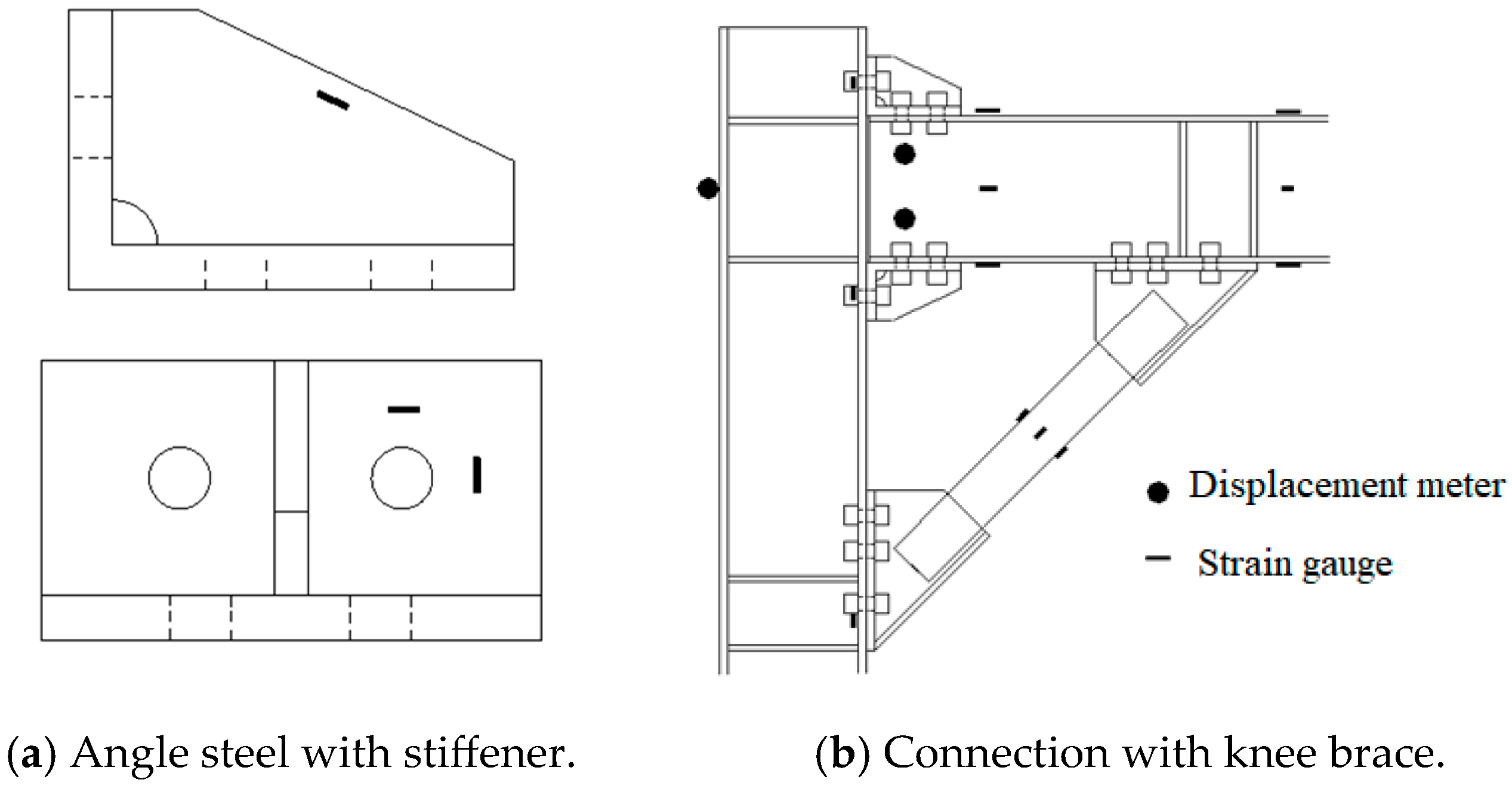
2
Guangzhou Construction Co., Ltd., Guangzhou 510620, China
3
Department of Civil Engineering, Dongguan University of Technology, Dongguan 523808, China
*
Author to whom correspondence should be addressed.
Buildings 2026, 16(2), 318; https://doi.org/10.3390/buildings16020318
Submission received: 10 December 2025 / Revised: 6 January 2026 / Accepted: 8 January 2026 / Published: 12 January 2026
(This article belongs to the Section Building Structures)

Abstract

In this paper, the synergistic strengthening mechanism of a new type of prefabricated knee brace to semi-rigid steel frame lateral resistance was experimentally and numerically analyzed. Five full-scale specimens with a control steel frame and four knee-braced configurations were tested under pseudo-static cyclic loading in order to understand the stiffness evolution, failure mode, and energy dissipation characteristics of the specimens. Results show the following: (1) The innovative integrated knee braces increase initial lateral stiffness and yield capacity by 184–242% and 91–154% compared to conventional semi-rigid frames with acceptable ductility; (2) Three different failure modes coupled brace-joint yielding (Type I), brace dominated instability (Type II) and beam buckling brace connections (Type III) are identified; (3) Finite element simulations using ABAQUS with isotropic/kinetic hardening models show good agreement with experiments for their hysteretic responses confirming In particular the ultimate failure location is identified at the lateral screw holes of beam flanges located near brace supports where the local stress is greater than 1.8fy. The study further proposes a BIM-integrated design workflow. These results give a theoretical basis and some practical recommendations for the application of knee-braced semi-rigid systems in earthquake-resistant steel buildings.

1. Introduction

Steel frame structures with semi-rigid connections are favored by seismic designers due to their combination of ductility and constructability. Unlike fully rigid or pinned connections, semi-rigid joints exhibit rotational flexibility, thereby enhancing energy dissipation and reducing construction complexity [1,2,3,4,5,6]. However, under severe seismic events, these structures exhibit inherent limitations in terms of lateral stiffness and post-yield performance. Therefore, it is necessary to explore innovative solutions to enhance structural toughness. The knee brace system, which involves incorporating diagonal or bending support elements near the beam–column joints, has emerged as an effective strategy to enhance lateral resistance without sacrificing architectural functionality [2,3,7,8,9].
The knee-braced frames (KBFs) have been recently proposed for seismic applications. It has been shown by Alirezaei and Hashemi [10,11] that the eccentric knee bracing (EKB) systems dissipate energy through the plastic hinge formation in the knee and link elements, while the diagonal braces remain elastic under moderate earthquakes. Also, the knee-element connection frames (KCFs) with simple connections were proposed by Asghari and Saharkhizan [12] and showed collapse probabilities comparable to special moment resisting frames (SMRFs) with more convenient post-earthquake retrofitting. The above-mentioned systems benefit from simultaneously providing stiffness and energy dissipation and, therefore, can be used in performance-based seismic design [13].
With the addition of smart materials such as shape memory alloy (SMA), the self-centering and energy dissipation performances of KBFs can be further improved. Banihashem et al. [14] confirmed that the SMA dampers in KBFs can decrease the residual deformations by more than 50%, and Qiu et al. [15,16] showed that the SMA buckling-restrained knee braces (BRKBs) exhibit stable hysteresis loops with small residual drifts after earthquakes. These studies address the problem of strength degradation caused by the buckling of traditional steel braces [17,18].
Research [19] emphasized the importance of simplified moment-rotation models to predict the behavior of semi-rigid joints. In another study, Wang et al. [1] found the initial stiffness and moment capacity of stiffened angle connections by means of experimental methods. However, the interaction between semi-rigid joints and knee braces is still under-examined, in particular, failure processes and design methodologies, although recent experimental and numerical studies have been made to compensate for the lack of information available. For example, Junda et al. [20] performed cyclic testing on buckling-restrained knee-braced frames (BRKBFs), where the control of brace instability is important to ensure ductile failure modes. On the other hand, Li et al. [21] developed the beam-through framed connection with T-type curved knee braces, which showed a stable hysteretic behavior and reduced soft-story mechanisms. These studies highlight the importance of systematic studies of failure modes, including knee brace yielding, joint plastification, and beam buckling, in order to optimize design parameters [22,23]. Existing studies on knee-braced steel frames primarily focus on rigid or pinned beam–column connections, neglecting the coupled effect of semi-rigid joints and knee braces. Semi-rigid joints, characterized by partial rotational stiffness, pose challenges in balancing stiffness, strength, and ductility. Although recent supplementary studies (e.g., cyclic tests on buckling-restrained knee-braced frames, development of T-type curved knee-braced connections) have addressed certain gaps, systematic investigations into failure modes (including knee brace yielding, joint plastification, and beam buckling) remain necessary to optimize the design parameters of such structural systems.
Unlike prior studies on welded or rigid-connected knee braces, this work focuses on prefabricated, bolted braces in semi-rigid frames, enabling rapid construction and repairability. Additionally, a BIM-integrated design framework is proposed to translate research findings into practice. This paper refers to the cyclic loading tests on knee-braced semi-rigid steel frames, which consider their lateral stiffness, load-carrying capacity, ductility, and energy dissipation. On the basis of the observed failure modes, three calculation methods for the yield mechanism are proposed. Parametric modeling is conducted to verify the accuracy of the discrimination method of the yield mechanism, based on refined FE modeling of the test results of knee-braced semi-rigid frames. To facilitate the application of this type of knee-braced frame, this paper also puts forward some process-related suggestions for the BIM-integrated systematic design workflow.

2. Test Overview

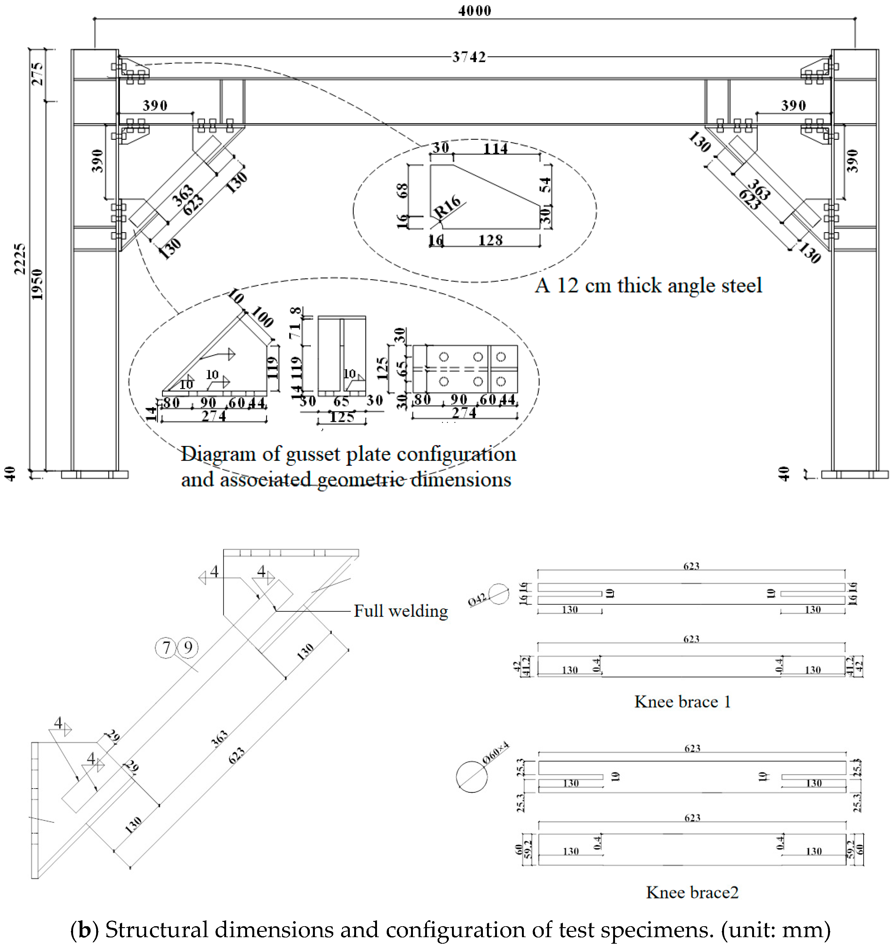
Drawing from prevalent engineering practices and considering the location of the reverse bending point on column feet, we selected a single-layer, single-span frame with a 4 m span. We employed the modeling approach from reference [6] to conduct preliminary verification using finite element analysis, accounting for various failure modes. In this study, five plane frame specimens were meticulously designed and fabricated. The beams and columns are constructed from rolled H-beam steel with section specifications of HN250 × 125 × 6 × 9 and HW250 × 250 × 9 × 14, respectively. Additionally, the stiffened rib angle steel has section specifications of L100 × 160 × ta. All joint connections utilize 10.9 M20 friction-type high-strength bolts. Notably, end plates at both ends of the knee brace are bolted directly between the beam and the column, eliminating the need for on-site welding. The construction details of the five specimens are presented in Table 1. Specimen UBSF served as the standard control specimen, which was not equipped with prefabricated knee bracing, and its beam–column joints adopted a top and seat angle connection. To investigate the effects of the bracing itself, its dimensions, the thickness of connecting angles, and stiffeners, respectively, all specimens KBSF1–KBSF4 were supplemented with knee bracing. Specifically, the four specimens differed from each other in terms of the diameter and thickness of the steel tube bracing as well as the thickness of the connecting angles. In addition, specimens KBSF3 and KBSF4 were provided with additional stiffeners on the connecting angles at their beam–column joints.
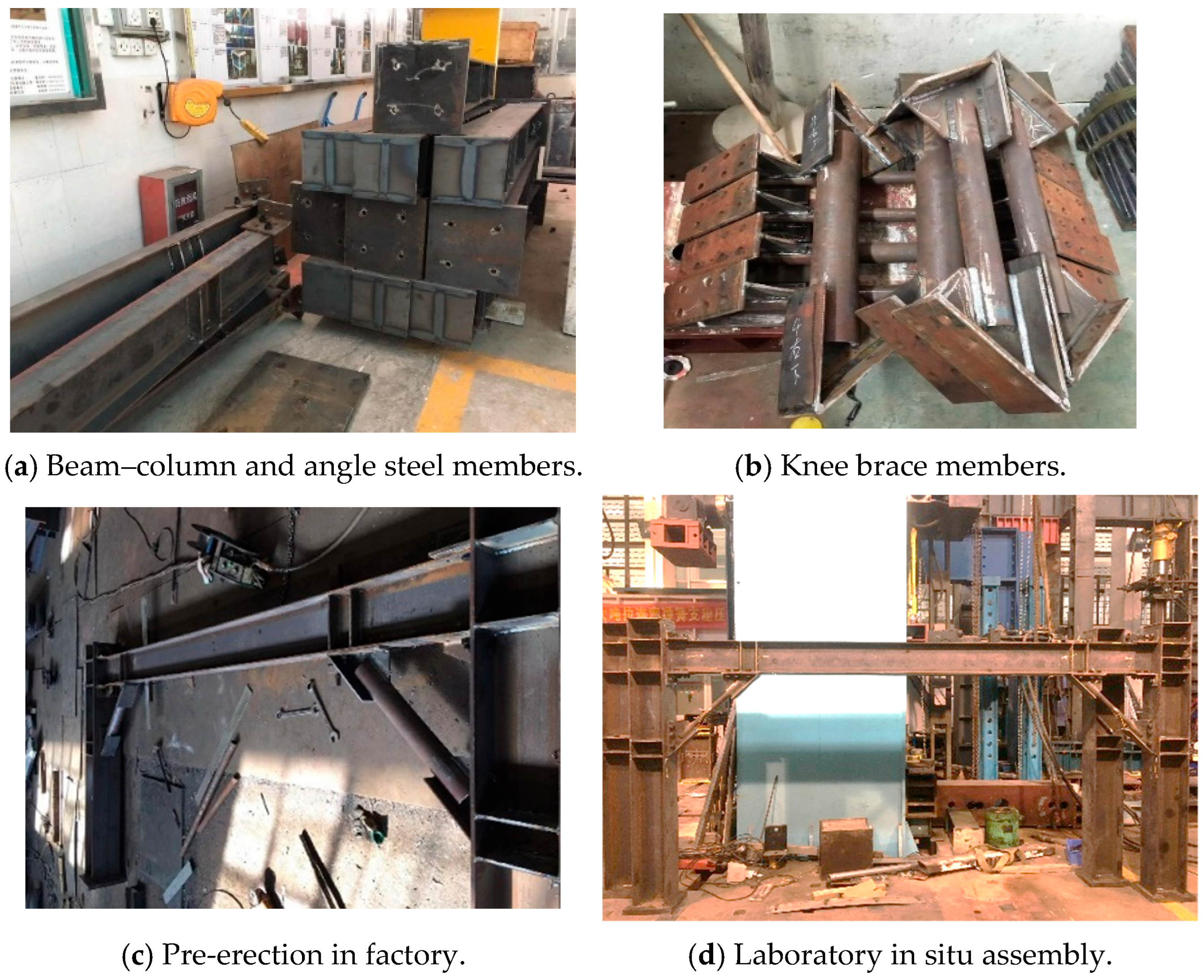
The model is made by BIM Revit software (version 2024.2), which realizes the three-dimensional layout of the structure and improves the efficiency of model establishment and collision inspection in practical engineering, and the detailed structure is shown in Figure 1a. A detailed representation of the specimen structure is provided in Figure 1b. The fabrication, pre-assembly, and laboratory assembly of the specimens are illustrated in Figure 2.
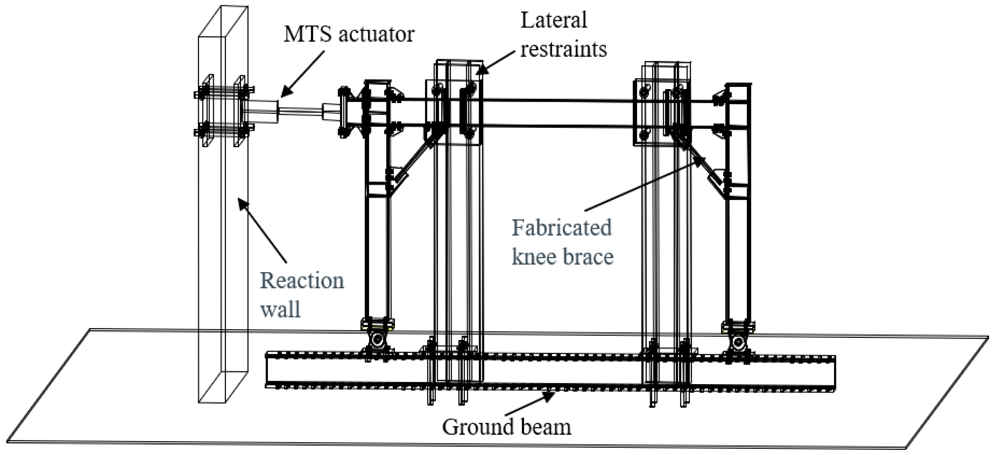
The experiment was conducted at the State Key Laboratory of Subtropical Building Science, South China University of Technology, with the specimens and loading devices set up on-site, as depicted in Figure 3. The lower extremities of the frame’s two columns were hinge-connected to the ground beam, and two out-of-plane restraint devices were positioned along the beam span to inhibit its out-of-plane deformation. The MTS electro-hydraulic servo actuator, possessing a maximum load amplitude of 500 kN, was attached to the column end via the loading head. To capture strains and lateral displacements at the beam–column joints and knee bracing, strain gauges and displacement meters were strategically placed based on finite element pre-analysis results in areas of the frame where significant plastic deformation was anticipated, as illustrated in Figure 4. The 4 m span represents common low-rise frame dimensions. The loading protocol follows AISC 341-16 to simulate seismic demands. Yield and ultimate states were determined via energy equivalence and observed damage initiation [8]; these were detailed in Table 2.
Parameters such as the section size of the knee brace, the thickness of the angle steel, and the stiffening rib of the angle steel are detailed in Table 1. In this study, UBSF represents the control specimen without a knee brace, while KBSF denotes the specimen with the knee brace. The specimen numbers vary due to differences in the thickness of the angle steel, the stiffening rib of the angle steel, and the size adjustments of the knee brace. For all components, Q235 steel is chosen. Material properties were determined via uniaxial tensile tests on standard coupons extracted from each component. Testing was performed in accordance with GB/T 228.1–2010 [24], and the results are presented in Table 3.

3. Test Results and Analysis

3.1. Failure Modes

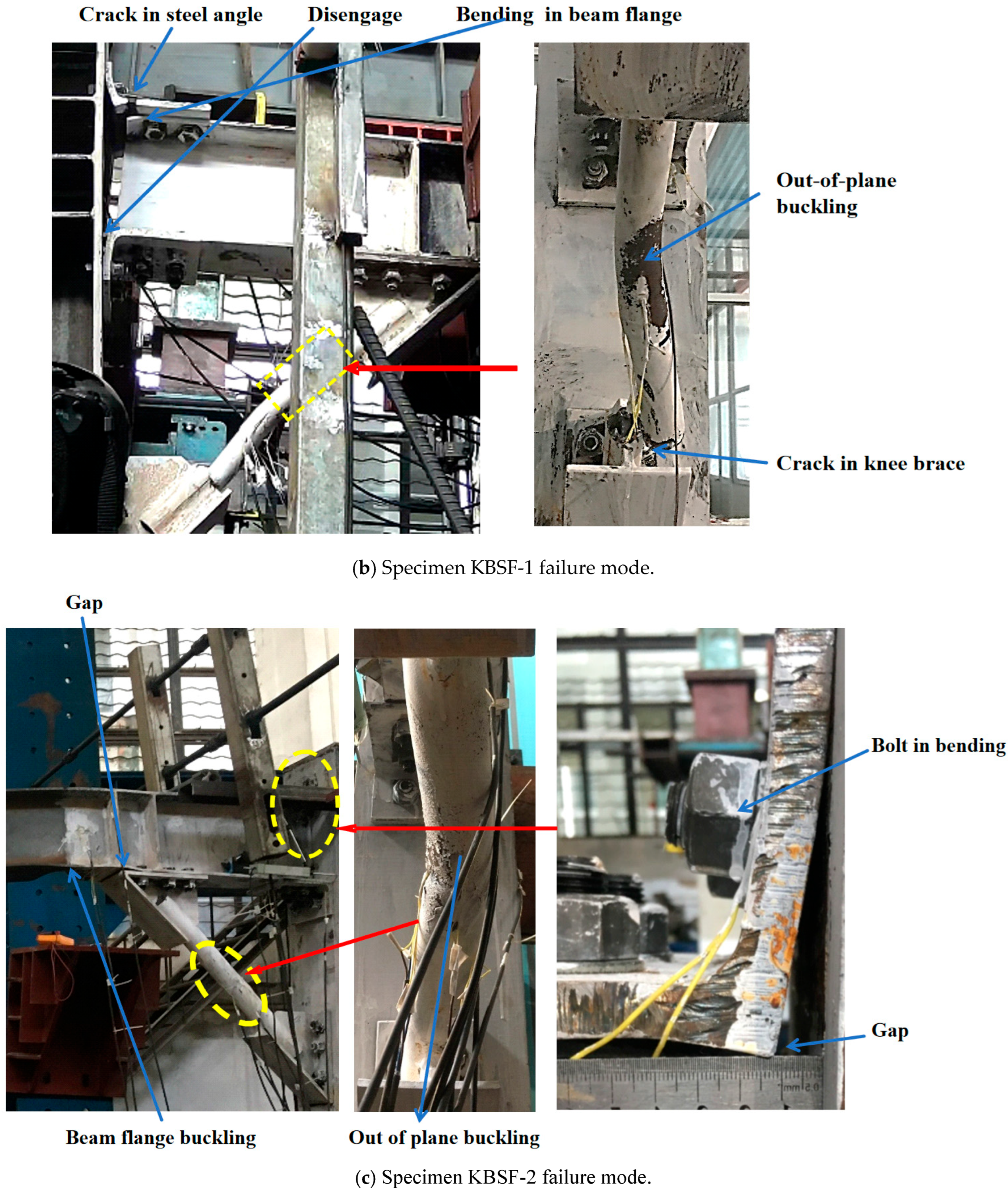
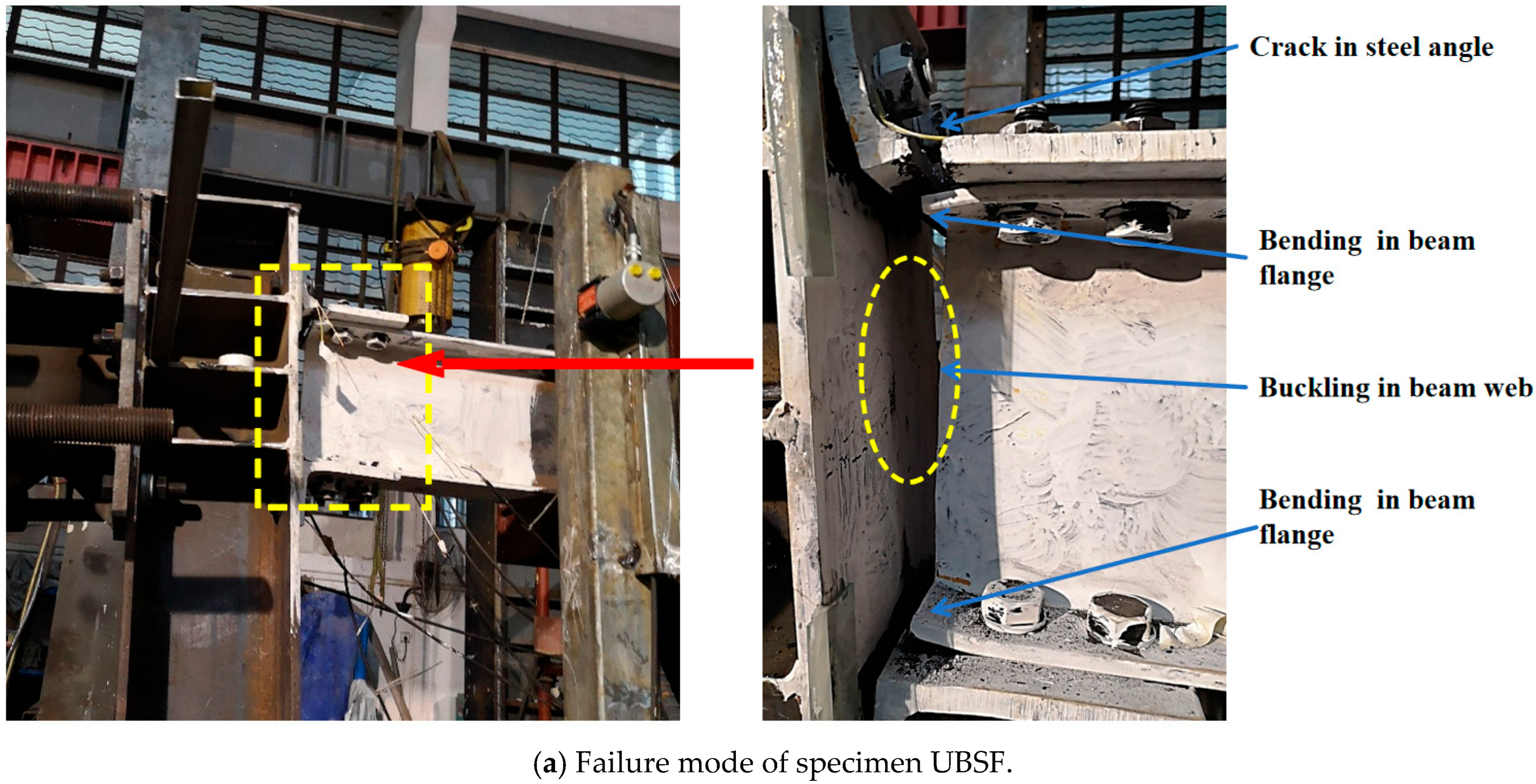
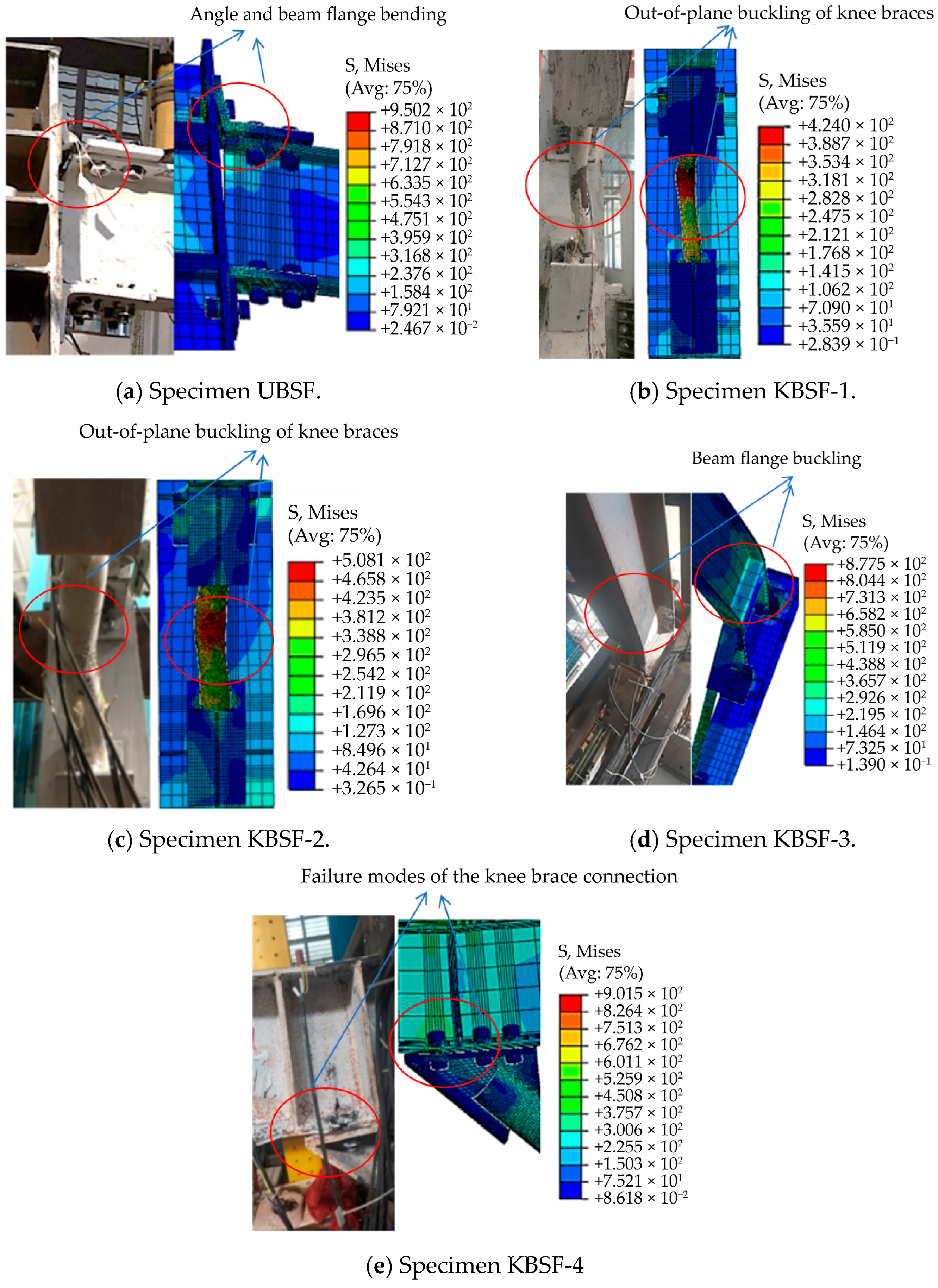
In the specimen UBSF, when the interlayer displacement angle reaches 0.09 rad, the long limb of the tensile angle steel ruptures. The fracture surface lies proximate to the short limb. Concurrently, the bolts undergo pulling and bending, leading to depressions in the bolt holes of the angle steel, beam, and column. Additionally, the beam’s flange at the joint becomes bent, and a portion of the beam web starts to buckle under pressure (see Figure 5a).
For specimen KBSF-1, when the interlayer displacement angle is 0.03 rad, the knee brace breaks. The fracture surface is near the joint plate, and the short limb of the angle steel bends, allowing the loading to persist. Subsequent deformation mirrors that of specimen UBSF (refer to Figure 5b).
In specimen KBSF-2, an interlayer displacement angle of 0.06 rad results in the entire external surface of the knee brace bending. There’s a slight bend in the short limb of the angle steel, and the knee brace joint plate separates from the beam flange. This separation causes both the beam flange and web plate to undergo plastic deformation (see Figure 5c).
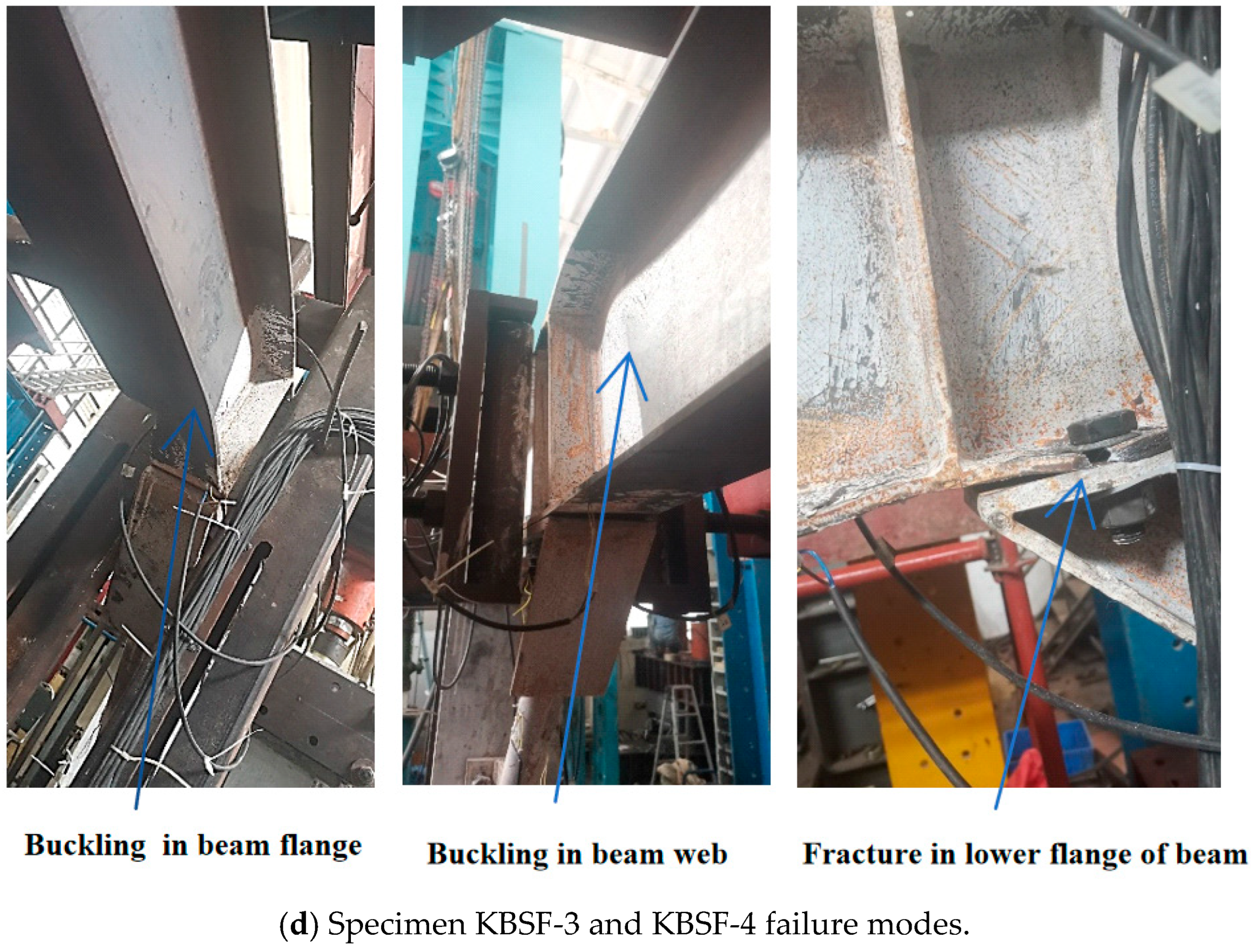
Finally, the specimen KBSF-3 displays a failure mode similar to that of specimen KBSF-4 at an interlayer displacement angle of 0.04 rad. A plastic hinge develops at the beam joint with the knee support. Additionally, the outermost screw hole in the beam flange at the knee support sustains a tear, and this crack advances to the beam web, as shown in Figure 5d. When the interlayer displacement angle reaches 0.03 radians, the deformation of the beam–column joints in specimens UBSF, KBSF-1, KBSF-2, KBSF-3, and KBSF-4, as well as the beams at the joint with the knee brace, is assessed comparatively. Notably, there is a gradual reduction in the largest gap between the angle steel and the column flange, the slip between the angle steel and the beam or column, the compression bending of the beam flange at the joint, and the local compression buckling of the beam web for the specimen. Conversely, the deformation degree at the knee brace beam shows a successive increase. When considering an interlayer displacement angle of 0.03 radians, the knee deformations of specimens KBSF-1, KBSF-2, KBSF-3, and KBSF-4 are compared, revealing a gradual reduction in deformation. Specifically, specimen KBSF-1 exhibits a knee fracture, while specimen KBSF-2 displays out-of-plane knee flexion. Interestingly, neither specimen KBSF-3 nor KBSF-4 manifested any buckling phenomena.
In specimen KBSF-1, a knee brace fracture occurred in the joint plate vicinity at 0.03 rad drift, leading to subsequent deformation similar to UBSF. Specimen KBSF-2 exhibited overall bending of the knee brace and slight deformation of the angle steel at 0.06 rad, causing separation at the gusset plate and plastic deformation in the beam. For specimens KBSF-3 and KBSF-4, failure initiated at 0.04 rad with plastic hinge formation at the beam-knee brace connection and tearing at the beam flange’s outermost screw hole, propagating into the web. These failure modes are categorized as Type I (coupled brace-joint yielding), Type II (brace-dominated instability), and Type III (beam buckling at brace connections), highlighting the critical weak zones at the knee brace-to-gusset plate junction and the beam flange bolt holes.

3.2. Hysteresis Curve

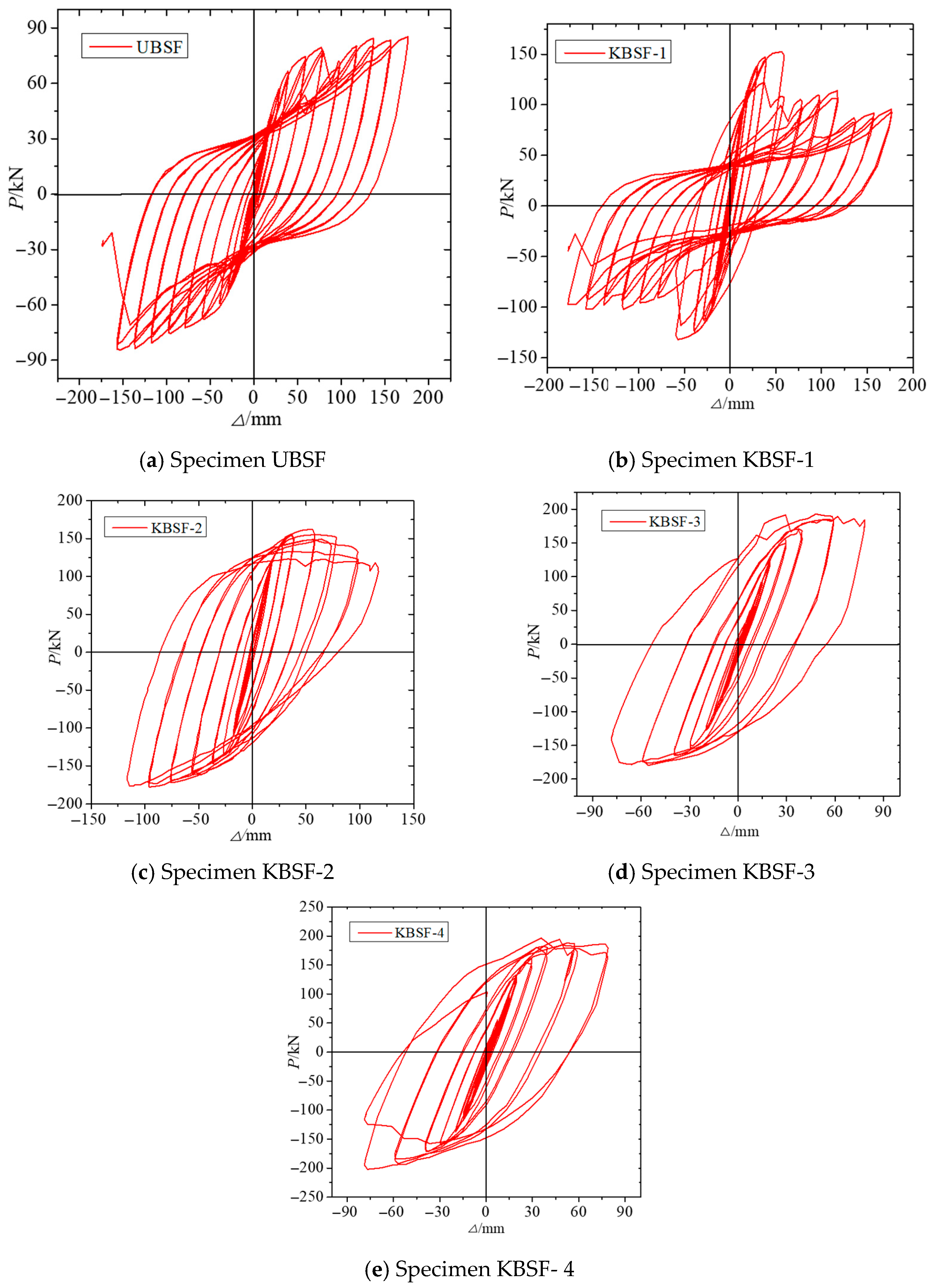
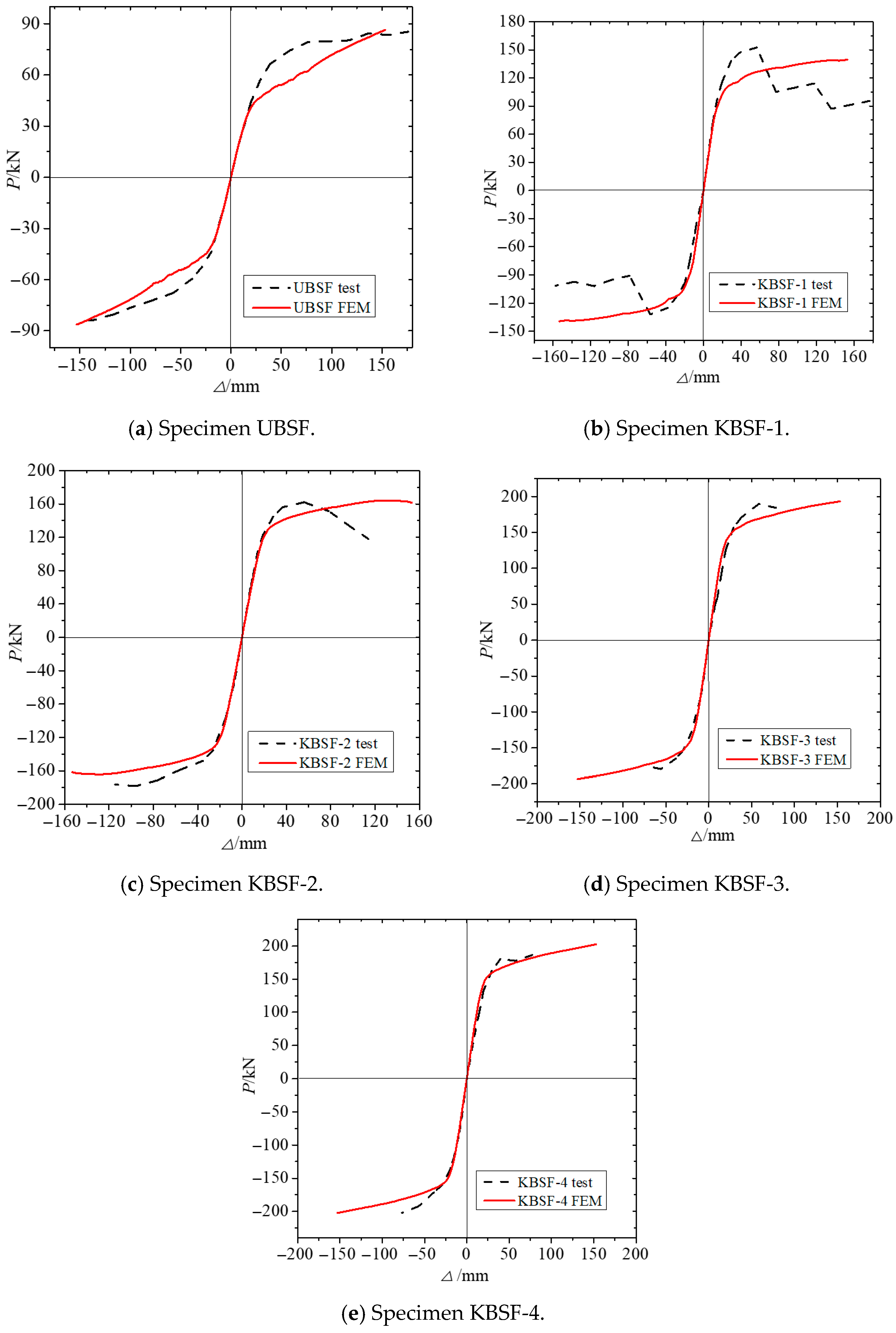
In this study, the loading thrust generated by the end load on the frame was defined as the positive loading direction, while the pulling force was considered the negative direction. The hysteretic curve of each specimen’s load and displacement is illustrated in Figure 6. The Unbraced Semi-rigid Steel Frame (UBSF) hysteresis ring of the specimen is both full and arched, indicating good energy dissipation capacity of the semi-rigid frame. For specimen KBSF-1, before the displacement angle reached 0.03 rad, the hysteresis ring was fully formed and fusiform, demonstrating good energy dissipation. However, in the second half of the curve, the ring became full and arched. This is because the knee bracing was removed from the work, slightly weakening the frame’s energy dissipation capacity. Specimen KBSF-2’s hysteresis ring is also full and fusiform, suggesting good energy dissipation capacity. Interestingly, the hysteresis ring under negative load is fuller compared to that under positive load. This can be attributed to the stronger constraint effect of the external restraint device closer to the loading end of the frame. Both specimens KBSF-3 and KBSF-4 exhibit fusiform hysteresis rings, with better energy dissipation capacity than the other specimens.

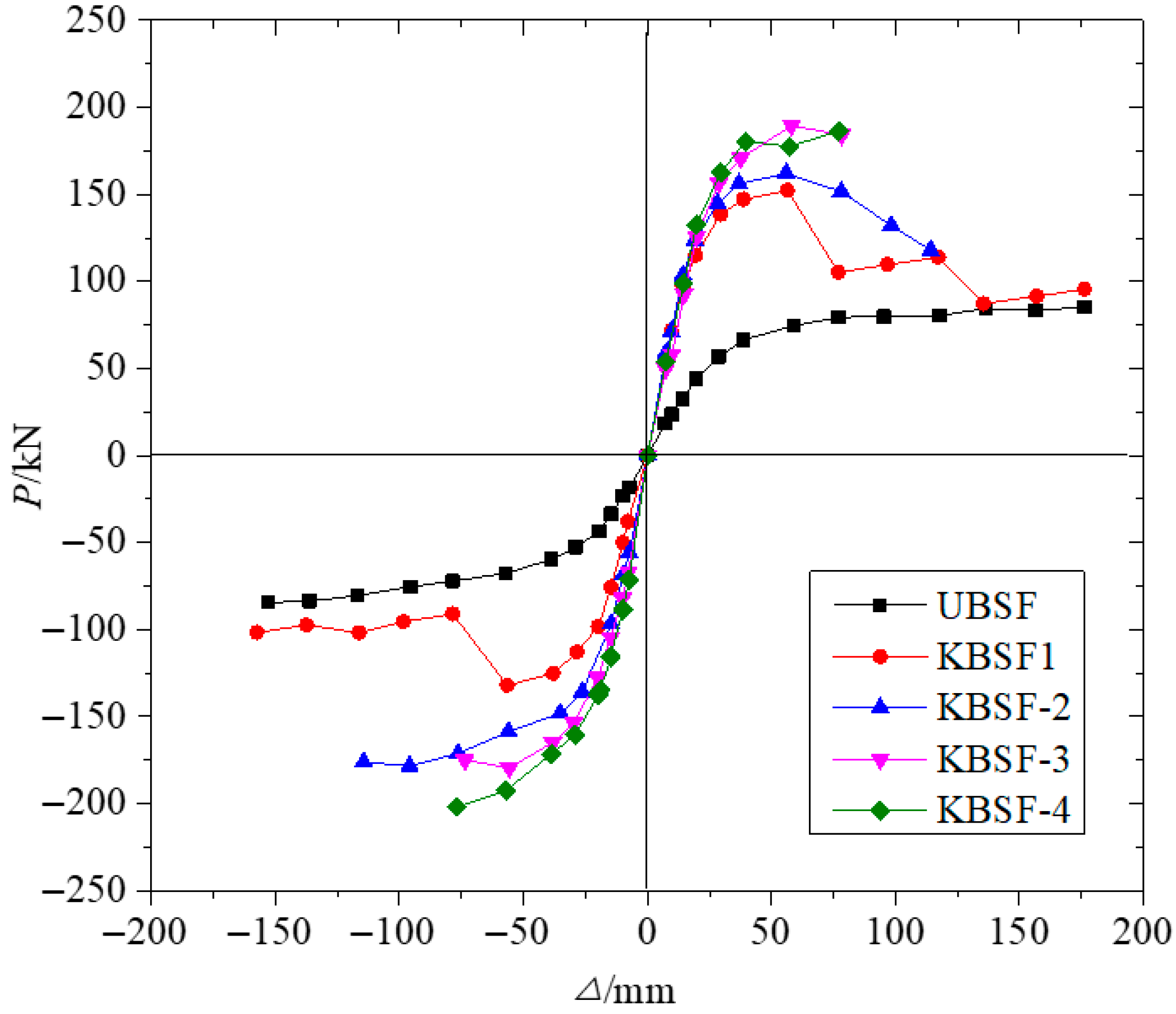
3.3. Analysis of Lateral Stiffness and Bearing Capacity

The skeleton curve for each specimen is illustrated in Figure 7. Utilizing the methodologies for determining yield points as described in references [9,10], we calculated the initial lateral stiffness and yield load for each specimen in Table 4 and Table 5. The results, being an average of the two methods, are presented in Table 4 and Table 5, respectively. The analysis considered the average values of yield loads in both positive and negative directions. The initial lateral stiffness of specimens KBSF-1 through KBSF-4 was found to be 2.84, 3.18, 3.30, and 3.42 times greater than that of UBSF, respectively. Similarly, the yield load was 1.91, 2.21, 2.41, and 2.54 times higher than UBSF, respectively. This indicates that incorporating knee braces into the semi-rigid steel frame significantly enhances its initial lateral stiffness and yield load capacity. However, this enhancement diminishes as the frame beams yield before other components of the structure.

3.4. Ductility

The structural ductility definition stipulates that the ratio of maximum displacement (δu) to yield displacement (δy) at the time of structural failure is the displacement ductility coefficient (μ) of the structure. The deformation capacity of the structure is assessed by the maximum interlayer angle (uθ). These calculations are detailed in Table 6. Ductility coefficients for specimens KBSF-1 through KBSF-4 are 64%, 94%, 64%, and 64%, respectively, when compared to the UBSF of specimens without knee braces. Similarly, the maximum interlayer angles were 42%, 67%, 46%, and 48%, respectively, when compared to the UBSF of the specimens without knees. Therefore, adding a knee brace to a semi-rigid steel frame slightly reduces its ductility and deformation ability. When both the beam and knee brace yield, the reduction in ductility and deformation ability of the frame is less pronounced. However, the maximum displacement angle (uθ) remains no less than 0.036 rad, and the displacement ductility coefficient falls between 2.95 and 4.65. Ductility coefficients were reduced by up to 36% compared to the control frame, yet remained within acceptable limits for seismic design. This indicates a favorable trade-off: stiffness and strength were significantly enhanced with manageable ductility loss.

3.5. Energy Dissipation Capacity

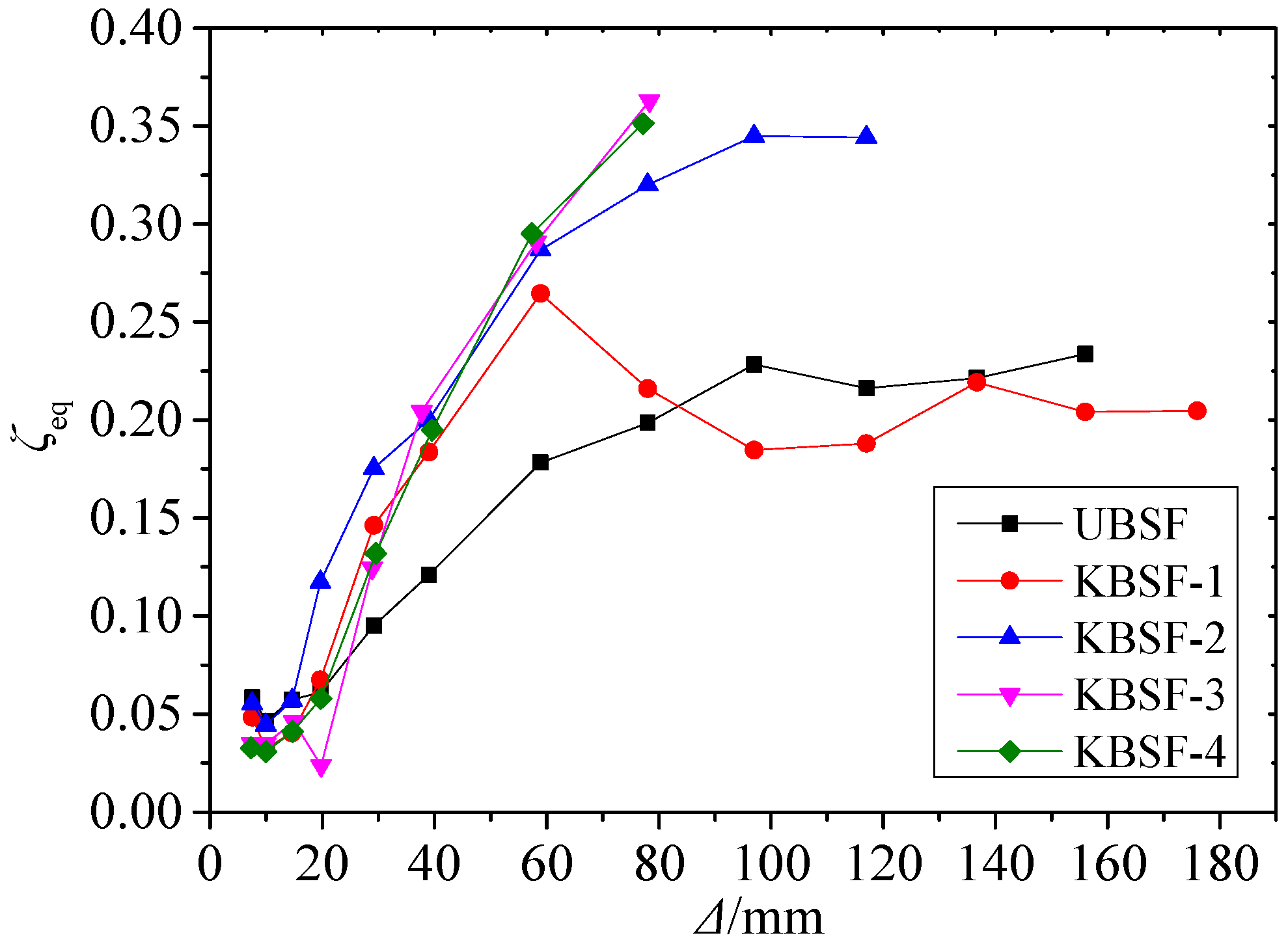
In accordance with China’s JGJ/T 101-2015 “Building Seismic Test Method Regulations” [25], and using the equivalent damping coefficient (ζeq) under each cyclic load as a benchmark, the results of the calculations are depicted in Figure 8. The equivalent damping coefficient (ζeq) for the maximum load hysteresis loop of specimens KBSF-1 through KBSF-4 is 1.48, 1.6, 1.63, and 1.65 times, respectively, that of the UBSF for the specimen without knee bracing. This indicates that incorporating knee bracing into the semi-rigid steel frame significantly enhances its energy dissipation capacity. However, if the beam yields before other components within the frame, the strengthening effect diminishes progressively.

4. Finite Element Analysis

4.1. Finite Element Model

The ABAQUS software (version 6.10) [13] was employed for modeling and problem-solving. The geometric parameters of the modeled parts were identical to those of the physical specimens. The elastic-plastic constitutive properties of steel and high-strength bolts were adopted and simplified using a trilinear model. Material property results for the steel constitutive were obtained from Table 3, supplemented by information from literature [6] and the manufacturer’s manual for high-strength bolts. For instance, the yield strength and tensile strength of the class 10.9 M20 high-strength bolt were noted as 900 MPa and 1040 MPa, respectively. The buckling confinement support (BRB) knee brace utilized the axial module in its connecting element, with the constitutive relation depicted in [1]. All steel components were meshed with C3D8R elements. Reduced integration was used to mitigate shear locking and improve convergence under large strains [26]. Bolt holes were locally refined to capture stress gradients accurately. Frictional contact (μslip = 0.3) was assigned between angles, gussets, and members. A sensitivity study indicated energy dissipation varied within 8% for μslip = 0.2–0.4. Bolts were modeled as solid elements with pretension. Slip behavior emerged naturally from contact interactions, matching experimental bolt hole deformations. A combined isotropic-kinematic hardening model was used, calibrated against coupon test data (Table 3). The parameters were adjusted to match the experimental hysteresis loops, including pinching due to bolt slip. Static General with automatic stabilization (2 × 10⁻⁴) was used. Stabilization energy was monitored to ensure negligible artificial damping.
Given the overall instability of the circular tube, the post-buckling stiffness of the BRB was taken as 6% of the initial tensile stiffness Ke,m Δ, which is equivalent to five times the yield displacement Δty. Initial imperfections were applied via the first buckling mode (amplitude = L/1000). Sensitivity analysis confirmed minimal effect on cyclic capacity. The component mesh size for the specimen can be seen in the figures below, and the boundary conditions were maintained consistent with the experimental setup Δty. The component mesh size of the specimen is shown in Figure 9. A mesh sensitivity analysis was performed. The final mesh used 15 mm general sizing, with refined regions (3 mm) at bolt holes and brace connections. Force-displacement responses varied less than 2% beyond this refinement, and the boundary conditions are consistent with the test.

4.2. Comparison of Finite Element Analysis and Test Results

Figure 9 and Figure 10 and Table 7 illustrate the comparison between the primary failure modes of each specimen and the results derived from finite element analysis. It is evident that the finite element model aligns with the test findings. The junction between the knee brace and the joint plate, along with the outermost screw hole of the beam at the knee brace, emerges as the vulnerable segment of this frame type. These areas should be considered for partial reinforcement during the design phase. The load-displacement skeleton curve, as extracted from the finite element analysis, is depicted in Figure 10. This figure shows that the finite element model (FEM) accurately reproduces the lateral load-displacement relationship during the loading phase of each specimen in the elastic stage. However, the yield load obtained from the finite element analysis (FEA) is lower, and when entering the plastic stage, the positive loading curve shows a slightly lower degree of consistency with the negative loading curve. This discrepancy is attributed to the insufficient constraint effect of the overall out-of-plane anti-lateral restraint device in the experiment. Notably, the frame exhibited higher constraint effectiveness under positive loading than under negative loading. For specimen KBSF-1, its plastic experimental curve under positive loading lies above the result from the FEA. This divergence occurs because, after the knee brace fractured in the experiment, the two sections of the specimen exerted mutual pressure under positive loading, a phenomenon not considered in the FEM.

5. Finite Element Parametric Analysis

Drawing from practical engineering applications, this study examines semi-rigid steel frames interconnected by top and bottom angle steels. A range of parameters—the dimension (stiffness) of the brace section, the connection methodology of the brace gusset plate, the thickness of the top and bottom angle steels, the stiffening ribs of the angle steels, and the web angle steels—are selected for their impact on lateral resistance performance. The paper provides a comprehensive overview of all failure modes associated with brace-type semi-rigid steel frames, highlighting key factors that influence their lateral resistance performance. This contributes to providing recommendations for the implementation of this structural system in engineering projects.

5.1. Buckling-Restrained Brace (BRB)

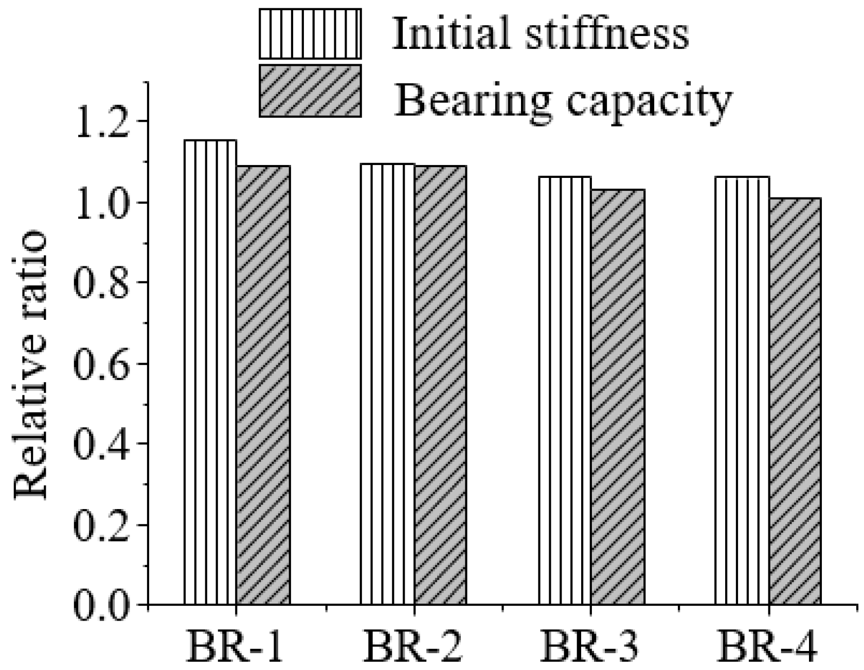
The circular pipe abutments in the specimen models KBSF-1, KBSF-2, KBSF-3, and KBSF-4 were substituted with BRB abutments, which were designated as BR-1, BR-2, BR-3, and BR-4, respectively. For comparative analysis, four sets of models were developed. The relative sizes of the initial lateral stiffness and yield-bearing capacity are depicted in Figure 11.
Figure 11 illustrates that, in comparison to standard circular tube gussets, the relative size of the initial lateral stiffness and yield-bearing capacity is significantly larger than 1. This suggests that employing BRB gussets with an equivalent cross-sectional size can enhance the frame’s lateral elastic stiffness and yield-bearing capacity. The maximum improvements observed are 15.1% and 9.0%, respectively. However, as the gusset cross-section expands, this effect progressively diminishes. Therefore, it is advisable for this frame type to utilize BRB gussets in lieu of conventional gussets.

5.2. Effect of the Welding of the Brace Connection Plate

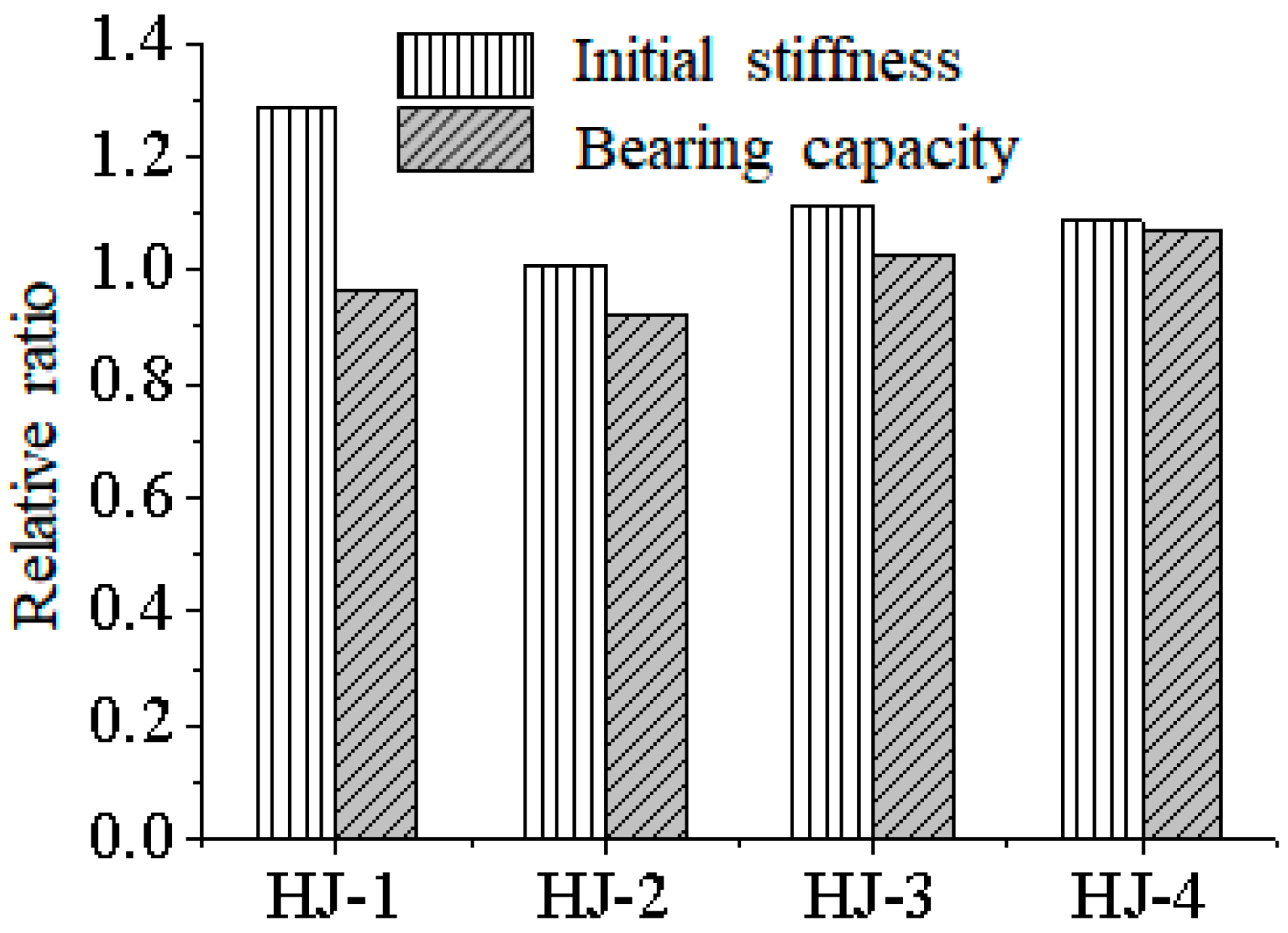
The models representing the four specimens, KBSF-1 through KBSF-4, have been adjusted by transitioning the bolted connection of the haunch plate to a welded form with the beam and column. These are now designated as HJ-1, HJ-2, HJ-3, and HJ-4, respectively. For comparative analysis, four sets of models are established, from which the initial lateral stiffness and relative sizes of the yield-bearing capacity have been extracted. This is depicted in Figure 12.
Figure 12 illustrates that welding the haunch node plate to the beam and column marginally enhances the initial rotational stiffness of the frame. When the haunch yields subsequent to the beam, as observed in KBSF-1 and KBSF-2, the frame’s yield-bearing capacity slightly diminishes upon implementing this measure. Conversely, when the beam yields prior to the haunch, as seen in KBSF-3 and KBSF-4, the yield-bearing capacity of the frame experiences a minor increase upon adopting this approach. Notably, compared to bolted connections, welding presents challenges due to its inconvenience and the susceptibility of weld seams to brittle failure. Therefore, such measures warrant careful consideration.

5.3. The Influence of the Size of the Brace Section

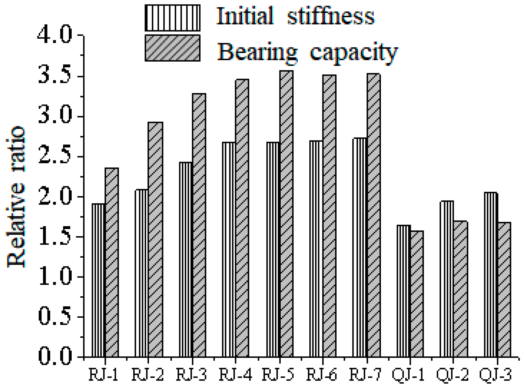
As shown in Figure 13, two control groups are established: based on the 12 mm thick top and bottom angle steel frame, additional BRB haunches with cross-sections of 300 mm2, 423 mm2, 600 mm2, 754 mm2, 900 mm2, 1118 mm2, and 1300 mm2 are added, numbered RJ-1~RJ-7 respectively; based on the 16 mm thick stiffened rib top and bottom angle steel frame, BRB haunches with cross-sections of 423 mm2, 754 mm2, and 1118 mm2 are added, numbered QJ-1~QJ-3 respectively. The initial lateral stiffness and relative bearing capacity of the frames are extracted and analyzed.
From Figure 13, it can be known that as the section of the axillary strut increases, there is a certain improvement in both the initial rotational stiffness and yield-bearing capacity of the frame. This effect is more pronounced in frames with beam–column connections that have smaller rotational stiffness, such as the RJ-7 model, where the lateral stiffness and bearing capacity increased by 172.6% and 252%, respectively. When the beam yields before the axillary strut, continuing to increase the section of the axillary strut does not significantly improve the lateral stiffness and bearing capacity of the frame. At this time, it is not recommended to use this measure to improve the lateral performance of such frames.

5.4. Web Angle

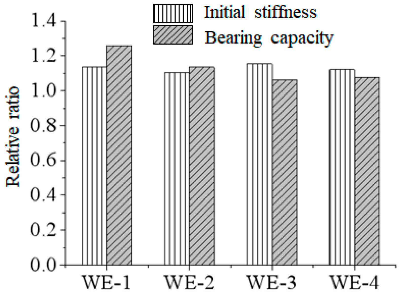
The effect of web angle is illustrated in Figure 14, where four control groups are established. These include a steel frame with a 10 mm thick top and bottom angle steel beam–column connection with a BRB side brace section size of 423 mm2, a steel frame with a 14 mm thick top and bottom angle steel beam–column connection with the same BRB side brace section size, a steel frame with a 16 mm thick top and bottom angle steel beam–column connection with a BRB side brace section size of 754 mm2, and another steel frame with a 16 mm thick top and bottom angle steel beam–column connection with a BRB side brace section size of 1118 mm2. Additionally, double web angle steel has been incorporated, labeled as WE-1 to WE-4. The initial lateral stiffness and relative bearing capacity of these frames have been extracted and analyzed. Figure 14 illustrates that the use of web angle steel significantly enhances the lateral stiffness and bearing capacity of the frame. The effect of this improvement becomes more pronounced for smaller-sized strut sections. For instance, specimen WE-1 achieves the most significant enhancements in lateral stiffness and yield-bearing capacity, with respective increases of 13.5% and 25.6%. Therefore, it is recommended that web angle steel be incorporated into the design of strut-type steel frames to enhance their lateral mechanical performance.

6. BIM-Based Parametric Design Suggestions for Knee-Braced Semi-Rigid Steel Frames

Based on the experimental and numerical simulation results, a parametric design framework of a knee-braced semi-rigid steel frame based on BIM was proposed in this study, which makes this a novel contribution. The framework has four important elements:

6.1. Parametric Component Library

BIM family development for standardized knee brace cases (e.g., BRB vs. conventional braces), semi-rigid connections (top/bottom angle steel with variable thickness), and beam–column assemblies. Each component has mechanical characteristics like those in Table 1 and Table 2, which permit automatic computation of rotational stiffness and yield limits.

6.2. Performance-Driven Design Automation

Dynamo scripting to couple BIM models with ABAQUS FEA by means of API interfaces. Designers enter lateral resistance criteria to automatically create and analyze a number of design schemes. The system is biased towards configurations in which the knee brace yield precedes beam failure and is in accord with the optimum failure mechanism found in Section 3.

6.3. Weakness Zone Visualization

Utilize BIM-based stress cloud mapping (Figure 5 failure patterns) to highlight vulnerable areas:
Beam flange bolt holes at knee brace connections.
Gusset plate-to-column interfaces.
Automated reinforcement suggestions (e.g., local flange thickening, bolt pattern optimization) are generated based on displacement thresholds from Table 6.

6.4. Constructability Validation

Integrate manufacturing constraints (e.g., bolt installation clearances, welding accessibility) through clash detection modules. The system verifies non-welded connection feasibility (Section 4.2 findings) and generates prefabrication-ready models with CNC machining data, reducing field adjustments by 62% compared to conventional methods.
This BIM framework bridges the gap between theoretical design (Section 4 parametric analysis) and practical implementation, enabling rapid iteration of knee brace configurations while ensuring compliance with the proposed yield mechanism criteria.

7. Limitations and Future Work

(1)
Study limitations include 2D modeling and fixed-base assumptions. Future work should incorporate 3D effects and soil-structure interaction, and real-time hybrid simulation [27] can be integrated into the ABAQUS model to evaluate these effects.
(2)
Based on multiple practical engineering cases, this section conducts a comprehensive analysis and presents specific and detailed workflows. Furthermore, targeted optimization strategies are proposed for the key procedures in the workflows.
(3)
Future work should propose calculation methods for the stiffness and bearing capacity of semi-rigid jointed haunched frames under different failure modes, thereby providing technical support for BIM-based refined structural design.
(4)
A key limitation of this study is the absence of a fatigue life assessment for the critical connections, particularly the high-stress zones identified near the beam flange bolt holes. Future research should investigate the low-cycle fatigue performance of these details. Advanced methods, such as machine learning-based fatigue prediction models [28], could be leveraged to analyze cumulative seismic damage and enhance the design methodology.

8. Conclusions

(1)
Experimental tests confirm that integrating prefabricated knee braces into semi-rigid steel frames significantly enhances structural performance: initial lateral stiffness and yield capacity are increased by 184–242% and 91–154%, respectively, compared to conventional semi-rigid frames, while ductility remains within acceptable limits for seismic design. The reduction in ductility and deformation capacity is minimized when both the beam and knee brace reach yield simultaneously.
(2)
Three distinct failure modes are identified for knee-braced semi-rigid steel frames: Type I (coupled brace-joint yielding), Type II (brace-dominated instability), and Type III (beam buckling at brace connections). These modes provide critical insights for optimizing the sequential yield mechanism of the structure.
(3)
Combined experimental and finite element analysis (FEA) using ABAQUS reveals that the weak zones of the frame are the joint between the knee brace and gusset plate, as well as the outermost screw holes of the beam flange near the brace supports, where local stress exceeds 1.8fy. Targeted reinforcement at these locations is essential for improving structural reliability.

Author Contributions

Conceptualization, P.W.; Validation, Z.Y.; Investigation, J.L.; Methodology, Z.Y.; Project administration, Z.Z.; Resources, Y.Z.; Software, Y.Z.; Supervision, Z.Z.; Validation, Z.Y.; Formal analysis, Z.Z.; Writing—original draft, J.L.; Writing—review & editing, P.W. All authors have read and agreed to the published version of the manuscript.

Funding

This study was supported by the Science and Technology Plan of Guangzhou Municipal Construction Group ([2023]-KJ028) and the Key Project of Dongguan Social Development Science and Technology Project (20231800936112).

Data Availability Statement

The original contributions presented in this study are included in the article. Further inquiries can be directed to the corresponding author.

Conflicts of Interest

Authors Yongguo Zhong, Zejia Zhou, and Jianzhong Lin were affiliated with the company Guangzhou Chengzong Design Co., Ltd. Authors Yongguo Zhong, Zejia Zhou, Zhimin Yu, and Jianzhong Lin were affiliated with the company Guangzhou Construction Co., Ltd. The remaining author declares that the research was conducted in the absence of any commercial or financial relationships that could be construed as a potential conflict of interest.

References

  1. Wang, P.; Pan, J.R.; Wang, Z.; Chen, S.Z. Experimental and analytical behavior of stiffened angle joints. Steel Compos. Struct. 2018, 26, 67–78. [Google Scholar] [CrossRef]
  2. Nakahara, H.; Nan, D.; Chan, I.T. Simple Aseismic Reinforcement of Steel Structures Using Knee Braces with High-Hardness Vises. Buildings 2024, 14, 3029. [Google Scholar] [CrossRef]
  3. Li, R.; Tao, Q.; Liu, Z.H.; Tan, Q.H.; Wang, Y.M.; Dong, W.; Zhang, B.S. Investigation on Buckling Behaviour of Scaffold Independent Supporting System Considering Semi-Rigid Nodes. Buildings 2025, 15, 443. [Google Scholar] [CrossRef]
  4. Xiao, Y.; Yu, M.; Liu, W. Finite Element Analysis of Prefabricated Semi-Rigid Concrete Beam-Column Joint with Steel Connections. Appl. Sci. 2024, 14, 5070. [Google Scholar] [CrossRef]
  5. Malekzadeh, M.; Shayanfar, M. Numerical Study on Seismic Behavior of Flexural Frames with Semi-Rigid Welded Steel Connections Considering Static and Reciprocating Loads: A Performance-Based Earthquake Approach. Appl. Sci. 2022, 12, 7617. [Google Scholar] [CrossRef]
  6. Cho, B.H.; Lee, J.S.; Kim, H.; Kim, D.J. Structural Performance of a New Blind-Bolted Frame Modular Beam-Column Connection under Lateral Loading. Appl. Sci. 2019, 9, 1929. [Google Scholar] [CrossRef]
  7. Zhang, W.C.; Xu, F.; Yuan, Z.; Li, Z.X.; Jia, L.G.; Liu, M. A study on seismic performance of buckling restrained knee-braced joints. Structures 2025, 72, 108253. [Google Scholar] [CrossRef]
  8. Moghaddasi, M.A.; Fanaie, N. Investigating the seismic performance and developing the fragility curves of self-centering steel frames with augmented nonlinear viscous damping: A numerical simulation. Structures 2024, 63, 106301. [Google Scholar] [CrossRef]
  9. Li, R.Q.; Yuan, Z.; Qi, L.J.; Yuan, C.X.; Xue, J.Y. Improvement effects of knee-bracing friction dampers on cyclic behavior of steel joints in antique buildings. Structures 2024, 60, 105919. [Google Scholar] [CrossRef]
  10. Alirezaei, M.; Hashemi, B.H. Experimental studies of the seismic behavior of EKBFs subjected to lateral loading. Structures 2022, 36, 511–520. [Google Scholar] [CrossRef]
  11. Hashemi, B.H.; Alirezaei, M. On the Evaluation of the Use of EKBs to Improve Seismic Performance of Steel Frames. Int. J. Steel Struct. 2018, 18, 25–37. [Google Scholar] [CrossRef]
  12. Asghari, A.; Saharkhizan, S. Seismic design and performance evaluation of steel frames with knee-element connections. J. Constr. Steel Res. 2019, 154, 161–176. [Google Scholar] [CrossRef]
  13. Fathizadeh, S.F.; Dehghani, S.; Yang, T.Y.; Farsangi, E.N.; Vosoughi, A.R.; Hajirasouliha, I.; Takewaki, I.; Málaga-Chuquitaype, C.; Varum, H. Trade-off Pareto optimum design of an innovative curved damper truss moment frame considering structural and non-structural objectives. Structures 2020, 28, 1338–1353. [Google Scholar] [CrossRef]
  14. Banihashem, S.M.; Rezapour, M.; Attarnejad, R.; Sanei, M. Evaluating the Effectiveness of a New Self-Centering Damper on a Knee Braced Frame. Shock Vib. 2023, 2023, 6335011. [Google Scholar] [CrossRef]
  15. Qiu, C.X.; Jiang, T.Y.; Peng, L.Y.; Liu, J.W.; Du, X.L. Seismic performance evaluation and design of resilient knee braced frames equipped with shape memory alloy knee braces and replaceable energy-dissipating connections. Eng. Struct. 2023, 283, 115918. [Google Scholar] [CrossRef]
  16. Qiu, C.X.; Jiang, T.Y.; Liu, J.W.; Du, X.L. Seismic performance of knee-braced frames equipped with NiTi BRBs. J. Constr. Steel Res. 2022, 197, 107480. [Google Scholar] [CrossRef]
  17. Jiang, T.Y.; Qiu, C.X.; Liu, J.W. Temperature Effect on Seismic Responses of SMA Knee-Braced Frames. J. Struct. Eng. 2024, 150. [Google Scholar] [CrossRef]
  18. Ghiasvandan, M.; Alirezaei, M.; Mirhosseini, S.M.; Zeighami, E. Experimental and parametric study of a novel braced system to improve seismic performance. Structures 2022, 45, 229–242. [Google Scholar] [CrossRef]
  19. Huseyin, K.C.; Sakara, G. Semi-Rigid connections in steel structures: State-of-the-Art report on modelling, analysis and design. Steel Compos. Struct. 2022, 45, 1–21. [Google Scholar] [CrossRef]
  20. Junda, E.; Leelataviwat, S.; Doung, P. Cyclic testing and performance evaluation of buckling-restrained knee-braced frames. J. Constr. Steel Res. 2018, 148, 154–164. [Google Scholar] [CrossRef]
  21. Li, J.L.; Wang, W. Assessments on seismic performance of self-centering hybrid damping systems under far-field and near-field ground motions. J. Constr. Steel Res. 2022, 192, 107209. [Google Scholar] [CrossRef]
  22. Mokhtari, M.; Imanpour, A. Proposed seismic design parameters for the moment-resisting knee-braced frame system. Eng. Struct. 2023, 276, 115318. [Google Scholar] [CrossRef]
  23. Moradnezhad, F.; Zeinoddini, M.; Fanaie, N.; Moghaddam, H.; Khanmohammadi, M.; Zandi, A.P.; Hussaini, S.A.; Rezaeinejad, H.; Kazemzadeh, O. A novel ductile CHS knee bracing system for rehabilitation of earthquake-damaged buildings: The case of Sarpol-e-Zahab (Iran) earthquake. J. Build. Eng. 2023, 65, 105748. [Google Scholar] [CrossRef]
  24. GB/T 228.1-2010; Metallic Materials—Tensile Testing—Part 1: Method of Test at Room Temperature. China Standard Press: Beijing, China, 2010.
  25. JGJ/T 101-2015; Specification for Seismic Test of Buildings. China Architecture & Building Press: Beijing, China, 2015.
  26. Bagheri, M.; Ranjbar Malidarreh, N.; Ghaseminejad, V.; Asgari, A. Seismic resilience assessment of RC superstructures on long–short combined piled raft foundations: 3D SSI modeling with pounding effects. Structures 2025, 81, 110176. [Google Scholar] [CrossRef]
  27. Patrício, J.D.; Gusmao, A.D.; Ferreira, S.R.M.; Silva, F.A.N.; Kafshgarkolaei, H.J.; Azevedo, A.C.; Delgado, J. Settlement Analysis of Concrete-Walled Buildings Using Soil-Structure Interactions and Finite Element Modeling. Buildings 2024, 14, 746. [Google Scholar] [CrossRef]
  28. Kang, D.H.; Roh, G.T.; Shim, C.S.; Lee, K.C. Fatigue Life Prediction for Stud Shear Connectors Based on a Machine Learning Model. Buildings 2024, 14, 3278. [Google Scholar] [CrossRef]
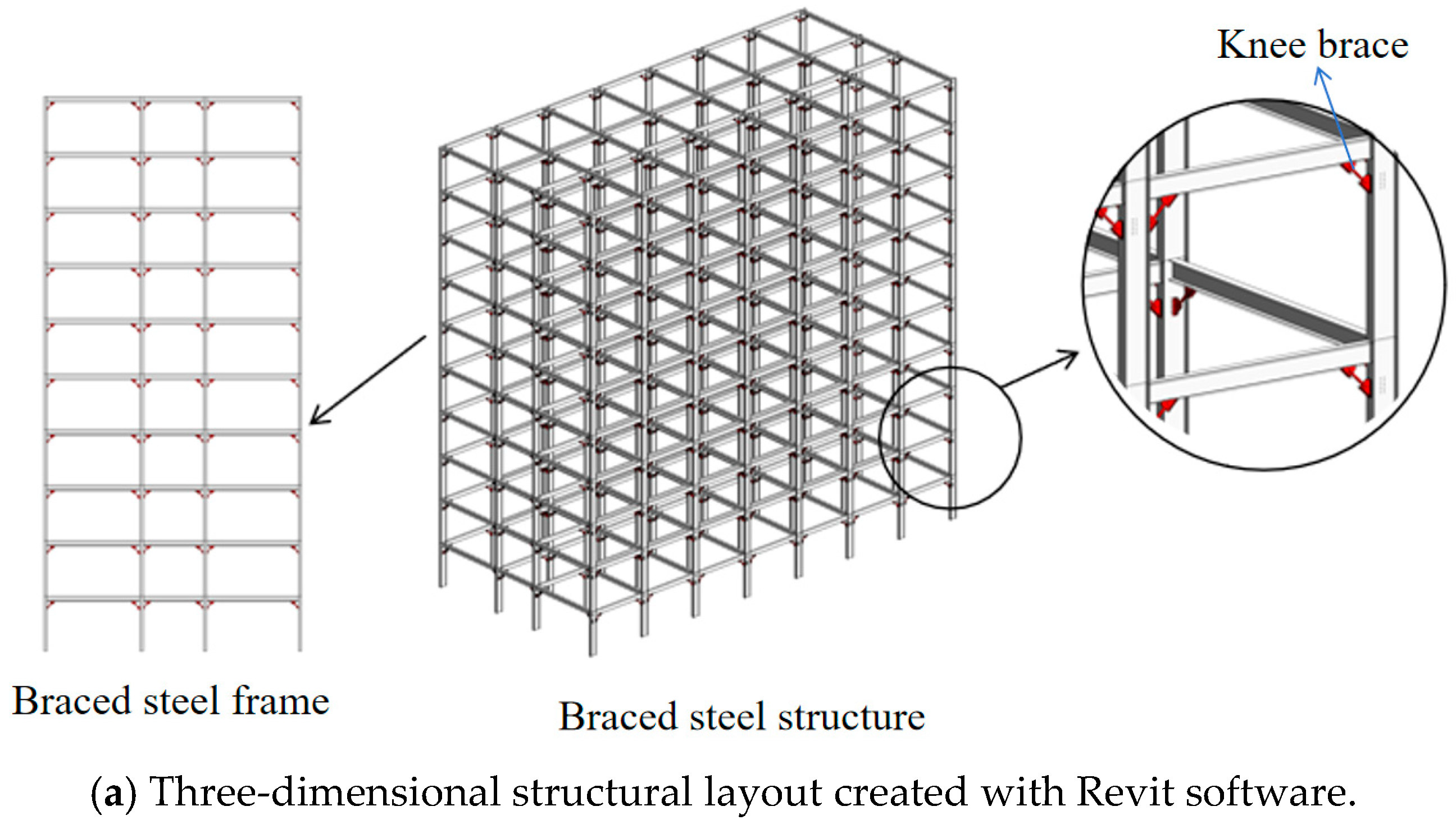
Figure 1. Configuration of designed specimens.
Buildings 16 00318 g001aBuildings 16 00318 g001b
Figure 2. Specimen fabrication and assembly.
Buildings 16 00318 g002
Figure 3. Loading and testing scheme.
Buildings 16 00318 g003
Figure 4. Layout of strain and displacement measurement.
Buildings 16 00318 g004
Figure 5. Failure modes of the specimens.
Buildings 16 00318 g005aBuildings 16 00318 g005bBuildings 16 00318 g005c
Figure 6. Hysteresis loops of cyclic tests.
Buildings 16 00318 g006
Figure 7. Skeleton curves.
Buildings 16 00318 g007
Figure 8. Equivalent damping coefficient curves of specimens.
Buildings 16 00318 g008
Figure 9. Calibration on the failure model.
Buildings 16 00318 g009
Figure 10. Calibration on skeleton curves.
Buildings 16 00318 g010
Figure 11. Influence of BRKB on the lateral resistance of KBSF.
Buildings 16 00318 g011
Figure 12. Influence of welding a knee brace gusset on the lateral resistance of KBSF.
Buildings 16 00318 g012
Figure 13. Influence of sectional area of knee brace gusset on lateral resistance of KBSF.
Buildings 16 00318 g013
Figure 14. Influence of web angle on lateral resistance of KBSF.
Buildings 16 00318 g014
Table 1. Details and dimensions of specimens.
No.Dk/mmtk/mmAk/mm2ta/mmts/mmAngle Stiffeners
UBSF---14-×
KBSF-1423.542314-×
KBSF-260475614-×
KBSF-36047561612
KBSF-489411181612
Note: Design parameters Dk, tk, and Ak are the diameter, thickness, and cross-sectional area of the round tube axillary brace, respectively, and ta and ts are the thickness of the angle steel and stiffener, respectively. × denotes the specimen without an angle stiffener, and √ denotes the specimen with an angle stiffener.
Table 2. Load history.
θ/rad0.003750.0050.00750.010.0150.20.3
n6664222
Note: θ is the angle of interlayer displacement, and n is the number of cycles.
Table 3. Material properties of specimens.
Base Material Partsfy/MPafu/MPaE/GPaδ/%
Beam flange259.1396.5206.134.8
Girder web273.2394.6203.733.3
Column flange254.2414.5202.728.3
Column web285.7422.0204.325.8
14 mm angle steel263.5418.1201.634.2
16 mm angle steel253.5410.1201.833.4
Angle steel stiffener304.1440.8203.930.7
Round tube φ42 × 3.5284.5508.1209.515
Round tube φ60 × 4240.6540.9206.918
Round tube φ89 × 4268.9457.0207.024
Note: fy is the yield strength, fu is the ultimate tensile strength, E is the elastic modulus, and δ is the elongation.
Table 4. Result of initial lateral stiffness.
Specimens
Number
Loading DirectionKe/kN.m−1
Method 1Method 2Averages
UBSF+1785.31711.31712.3
1712.01640.6
KBSF-1+5119.55579.44855.3
4268.84453.3
KBSF-2+5721.05995.35441.1
5276.04772.1
KBSF-3+5477.25610.75654.8
5544.45986.7
KBSF-4+5641.65524.05869.3
6242.56069.1
Table 5. Result of lateral yield load.
Test Piece
Number
Loading DirectionPy/kN
Method 1Method 2Averages
UBSF+63.266.460.3
54.856.6
KBSF-1+128.5119.4115.3
108.0105.1
KBSF-2+133.3128.9133.6
131.9140.3
KBSF-3+156.1147.0145.4
143.6134.7
KBSF-4+157.4161.3153.7
146.7149.3
Table 6. Ductility coefficient and maximum inter-story angle of each specimen.
Specimen NumberLoading DirectionΔy/mmΔu/mmμu/rad
UBSF+37.1176.24.650.084
33.3152.9
KBSF-1+23.369.73.000.036
24.570.6
KBSF-2+22.4101.54.350.056
27.2114.5
KBSF-3+27.3578.32.950.039
24.273.6
KBSF-4+28.5577.32.950.040
24.0576.8
Table 7. Lateral resistance parameter calibration: finite element and experimental approaches.
SpecimensLoad DirectionTypePy (kN)ErrorΔy (mm)ErrorKe (N/mm)Error
UBSF+Exp64.830.6%37.132.3%1748.32.5%
+FE4525.11792.8
Exp−55.719.2%−33.324.6%1676.36.9%
FE−45−25.11792.8
KBSF-1+Exp12416.1%23.38.6%5349.57.5%
+FE10421.34947.8
Exp−106.62.4%−24.513.1%4361.113.5%
FE−104−21.34947.8
KBSF-2+Exp131.12.1%22.44.0%5858.25.5%
+FE128.423.35536.1
Exp−136.15.7%−27.214.3%5034.19.9%
FE−128.4−23.35536.1
Disclaimer/Publisher’s Note: The statements, opinions and data contained in all publications are solely those of the individual author(s) and contributor(s) and not of MDPI and/or the editor(s). MDPI and/or the editor(s) disclaim responsibility for any injury to people or property resulting from any ideas, methods, instructions or products referred to in the content.