Article

Propagation Characteristics of Railway-Induced Ground Vibration in Different Soil Conditions and Vibration Isolation Performance of Infilled Trenches

China Academy of Building Research, Beijing 100013, China
*
Author to whom correspondence should be addressed.
Buildings 2026, 16(17), 3412; https://doi.org/10.3390/buildings16173412
Submission received: 13 July 2026 / Revised: 8 August 2026 / Accepted: 18 August 2026 / Published: 26 August 2026
(This article belongs to the Special Issue Advances in Vibration Control of Civil Structures)

Abstract

With the rapid expansion of urban rail transit networks, ground vibrations induced by train operations have attracted increasing attention due to their environmental impacts. In this study, a numerical simulation approach was employed to systematically investigate the propagation characteristics of railway-induced ground vibrations under different soil conditions and to evaluate the vibration isolation performance of in-filled trenches. The results indicate that vibration amplitudes exhibit an oscillatory attenuation pattern during propagation. A pronounced vibration amplification zone dominated by Rayleigh waves is observed on the ground surface. This phenomenon can be attributed to the phase differences among P waves, S waves, and Rayleigh waves with different frequency components, which arise from their distinct wave numbers and subsequently lead to constructive and destructive wave interference. As the elastic modulus of the soil increases, the overall vibration response decreases, while the proportion of high-frequency vibration components gradually increases. Regarding vibration mitigation measures, the vibration isolation performance of trenches filled with expanded polystyrene foam and concrete was comparatively investigated. The results demonstrate that the flexible EPS-filled trench provides significantly better vibration isolation than the rigid concrete-filled trench. Increasing the trench depth further improves the isolation performance of the flexible trench, whereas increasing the depth of the concrete-filled trench produces little improvement and may even amplify vibration responses behind the trench. The findings of this study provide a theoretical basis for predicting railway-induced environmental vibrations and optimizing the design of wave-path vibration isolation measures.

1. Introduction

With the rapid development of modern cities, urban rail transit has become an indispensable component of daily transportation. However, the continuous interaction between train wheels and rails during train operation generates persistent low-level vibrations. These vibrations are transmitted through the track structure into the surrounding soil, forming a propagating ground vibration field [1,2]. Although railway-induced vibrations generally do not threaten structural safety, they may significantly reduce the living comfort of nearby residents and interfere with the normal operation of precision instruments [3]. Long-term exposure to railway vibration has also been reported to adversely affect human health [4]. Therefore, understanding the propagation characteristics of railway-induced vibrations in a semi-infinite elastic medium and developing effective vibration mitigation techniques have become important research topics in railway engineering and environmental vibration control.
The fundamental source of train-induced ground vibration lies in the dynamic interaction between the vehicle and the track system. Previous studies have shown that vibration excitation is mainly generated at the wheel–rail contact interface, where track irregularities and wheel imperfections serve as the primary excitation sources [5]. During propagation through the surrounding ground, the vibration response is influenced by various factors, among which soil properties play a particularly significant role. As one of the key parameters describing soil stiffness, the elastic modulus directly affects the dynamic response of the ground. For a homogeneous ground, the vibration level generally decreases with increasing soil stiffness [6,7]. Most previous studies have demonstrated that soft soils are characterized by larger vibration amplitudes, richer low-frequency components, and longer propagation distances, whereas stiff soils exhibit faster attenuation of vibration amplitudes and relatively stronger high-frequency components [8,9]. Zhao et al. [10] further reported that the soil conditions beneath tunnels significantly influence vibration responses. In addition, soil damping characteristics also affect the attenuation rate of vibration with horizontal distance, and highly damped soils can effectively suppress the far-field propagation of vibration waves [11]. Therefore, a systematic comparison of vibration propagation characteristics under different soil stiffness conditions is essential for understanding the governing role of soil mechanical properties in railway-induced ground vibrations.
Numerous studies have indicated that low-frequency vibrations propagate over considerably longer distances than high-frequency vibrations [12,13]. In general, vibration amplitudes gradually decrease because of both material damping and geometric attenuation [14]. Nevertheless, abnormal vibration amplification has frequently been observed at specific distances from the vibration source [15,16,17]. The mechanism responsible for the formation of these vibration amplification zones remains controversial. Krylov [18] and Motazedian et al. [19] suggested that vibration amplification occurs when the train speed exceeds the Rayleigh wave velocity of the supporting soil. Yu et al. [20] attributed this phenomenon to Rayleigh-wave resonance in layered soils, whereas Auersch [11] argued that vibration amplification mainly results from wave scattering. Consequently, no unified explanation has yet been established, and existing theories are generally based on specific assumptions or localized observations without providing a comprehensive interpretation of the coupled propagation of multiple elastic waves.
To mitigate railway-induced ground vibrations, installing vibration isolation barriers along the wave propagation path has become one of the most widely adopted strategies. The underlying principle is to introduce a discontinuity in wave impedance between the vibration source and the protected area, thereby causing incident waves to be reflected, scattered, or diffracted and consequently reducing the transmission of vibration energy to the far field [21]. Among various wave-barrier techniques, vibration isolation trenches are the most classical and can be classified into open trenches and in-filled trenches. Owing to the substantial wave impedance contrast between air and soil, open trenches generally exhibit excellent vibration isolation performance. Çelebi et al. [22] reported that open trenches can reduce vibration amplitudes by approximately 80%. However, practical applications of open trenches are limited because of construction safety and stability issues [23]. Compared with open trenches, in-filled trenches generally provide lower vibration isolation efficiency, and their performance strongly depends on the properties of the filling material [24]. Previous studies have also demonstrated that trench geometry is an important influencing factor, with trench depth exerting a much greater influence on vibration isolation effectiveness than trench width [25]. Although considerable research has been devoted to investigating the mechanisms and influencing factors of vibration isolation trenches, relatively little attention has been paid to the influence of soil properties on their vibration isolation performance.
Motivated by these considerations, this study aims to address the limited understanding of how soil stiffness influences railway-induced ground vibration propagation and attenuation mechanisms. Numerical simulations are conducted to investigate the vibration propagation characteristics in homogeneous soils with different elastic moduli, revealing the dependence of wave transmission and vibration amplification on soil mechanical properties. Unlike previous studies that mainly evaluate vibration responses based on numerical observations, an elastic-wave-interference-based theoretical framework is proposed to explain the formation mechanism of vibration amplification zones. Furthermore, the vibration isolation performance of in-filled trenches under different soil conditions is systematically evaluated, providing theoretical guidance for environmental vibration prediction and the optimal design of railway vibration mitigation measures. The findings provide new insights into environmental vibration prediction and offer theoretical guidance for the design of railway vibration mitigation measures.

2. Numerical Simulation Method

Compared with analytical methods and field measurement approaches, numerical simulation offers significant advantages in handling complex vehicle–track–ground interaction systems and predicting vibration responses under various operating conditions. Owing to its high computational efficiency and flexibility, numerical simulation has become one of the most widely adopted techniques for railway-induced vibration prediction. Therefore, the numerical simulation method is employed in this study to investigate the propagation characteristics of railway-induced ground vibrations.

2.1. Vehicle–Track Coupled System

To determine the wheel–rail excitation, a vehicle–track coupled dynamic model was first established to calculate the dynamic interaction between the vehicle and the track, thereby obtaining the excitation forces acting on the rail nodes.
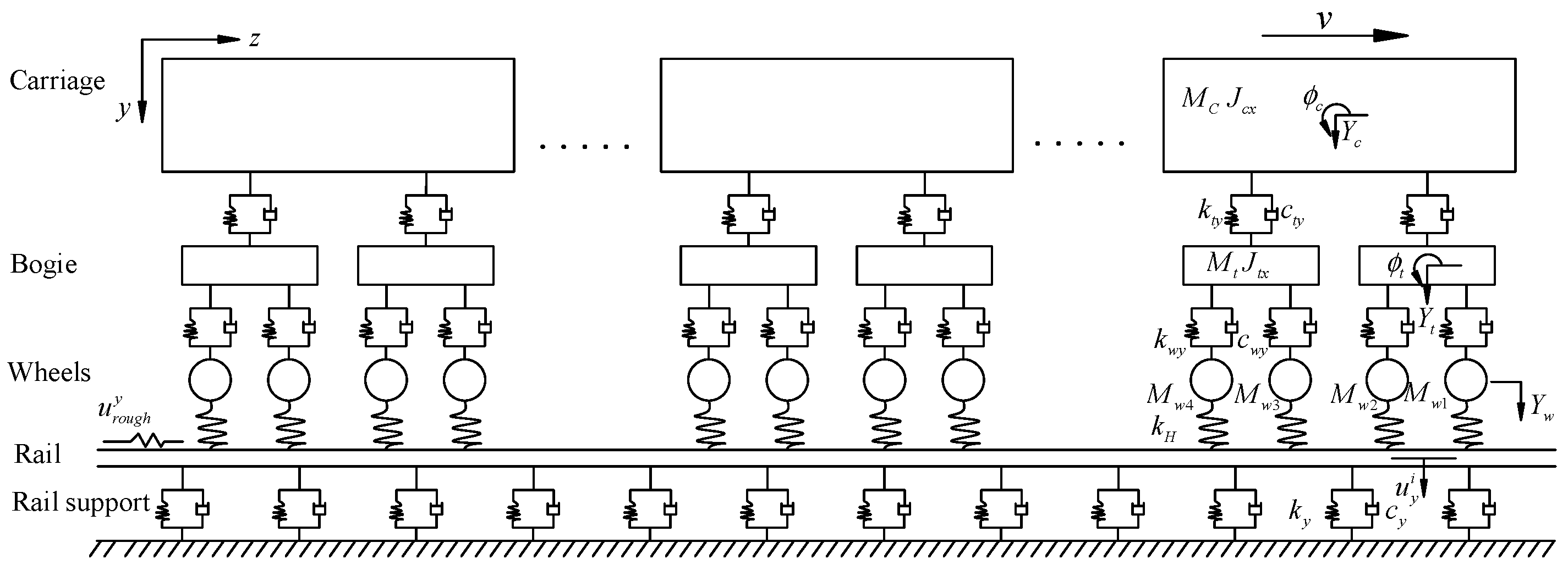
According to the structural characteristics of a railway vehicle, the three-dimensional vehicle dynamics model consists of seven rigid bodies, including one car body, two bogies, and four wheelsets. Only rigid-body motions are considered, while elastic deformation and structural vibration of each component are neglected. The wheelsets are connected to the bogies through the primary suspension system, whereas the car body is connected to the bogies through the secondary suspension system. Based on the motion characteristics of each component, the degrees of freedom (DOFs) of the vehicle model are defined as follows: the car body possesses five DOFs; each bogie also possesses five DOFs; each wheelset possesses four DOFs. Consequently, the complete vehicle model contains 35 degrees of freedom. The vehicle parameters, including the mass, moment of inertia, suspension stiffness, and damping coefficients, were adopted from a typical metro vehicle. The track is modeled as a slab ballastless track, where only the discrete support provided by the rail fasteners is considered. The rail fasteners were simulated using spring–damper elements, with the corresponding stiffness and damping parameters determined according to the track design specifications. Continuous wheel–rail contact is assumed throughout the analysis. The normal contact force is governed by Hertzian contact theory, whereas the tangential interaction is described using Kalker’s creep theory. Track irregularity was considered as the excitation source for the wheel–rail interaction analysis. Based on these assumptions, the vehicle–track coupled model is established, as shown in Figure 1.
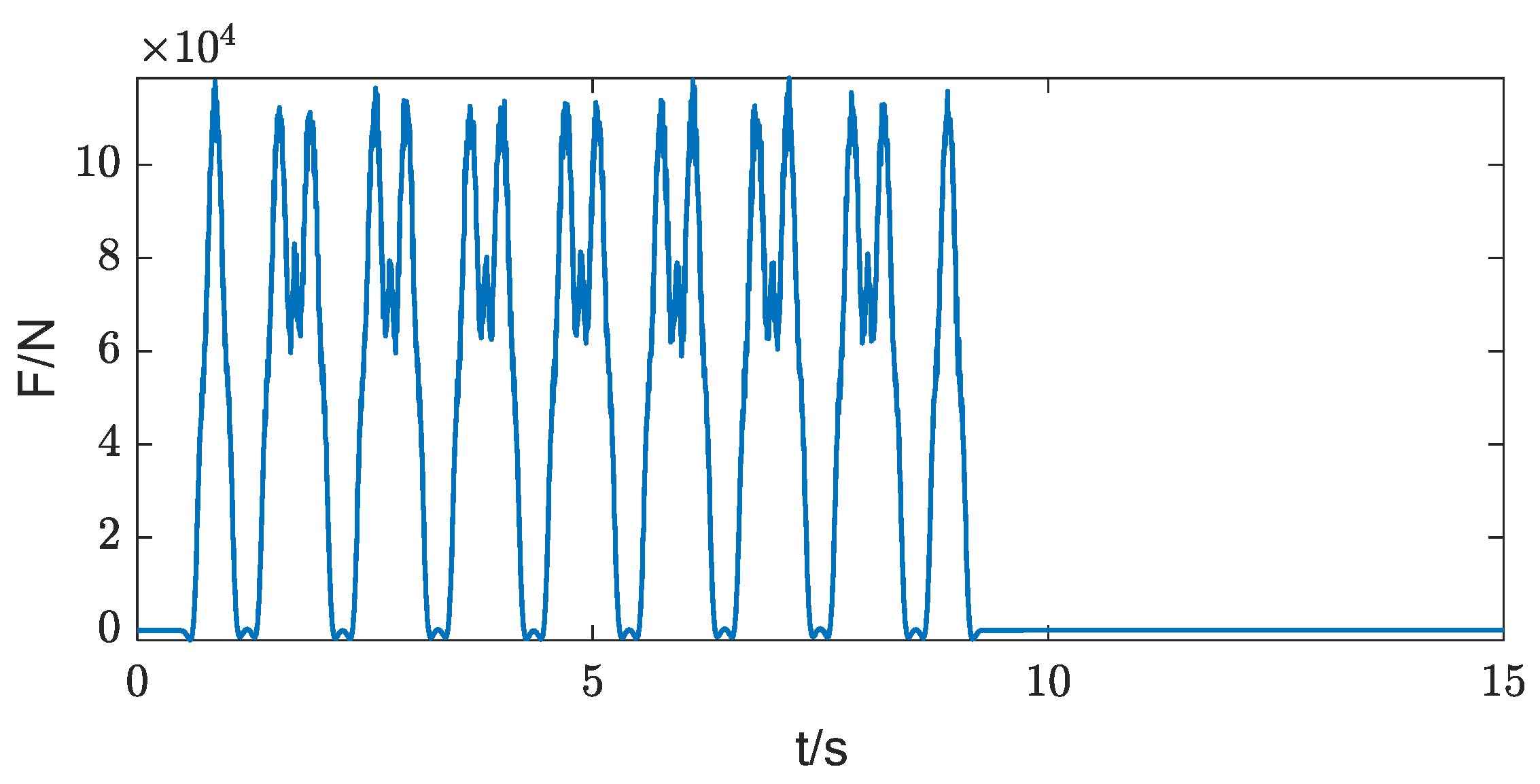
Accordingly, the dynamic equilibrium equation of the vehicle–track coupled system is established and solved using the Newmark-β integration method. The resulting vertical wheel–rail excitation time history at the rail nodes, with a node spacing of 2.0 m for a train operating at a speed of 80 km/h, is shown in Figure 2.

2.2. Tunnel–Soil Coupled System

Since railway-induced vibration belongs to the category of low-amplitude environmental vibration, the induced soil strain generally remains within the elastic range. Therefore, the tunnel–soil system is modeled as a linear elastic medium. To establish an efficient and reliable numerical model, several key modeling parameters are carefully determined by balancing computational efficiency and numerical accuracy.
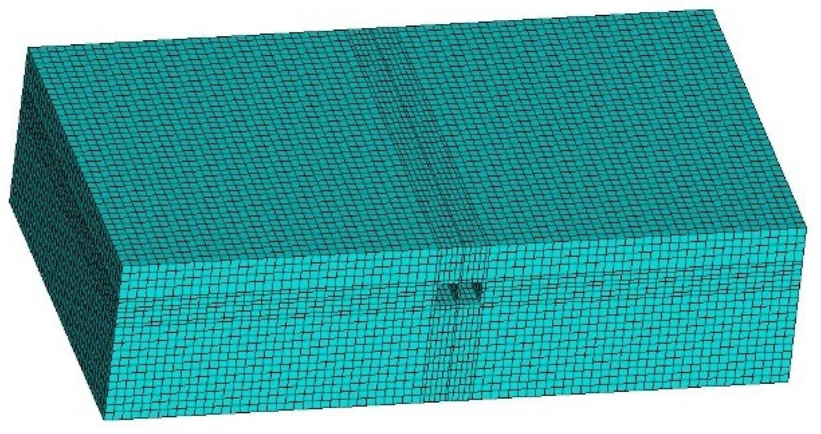
An excessively large finite element size may introduce low-pass filtering and numerical dispersion, thereby reducing computational accuracy, whereas excessively small elements significantly increase computational cost. According to previous studies, the element size should be smaller than one-sixth of the minimum shear-wave wavelength to ensure sufficient accuracy. Accordingly, the element size adopted in this study ranges from 0.8 m to 2.0 m. The same mesh configuration was adopted for all simulation cases to ensure that the differences in vibration responses were mainly attributed to the investigated conditions rather than mesh variation. The computational domain must also be sufficiently large to eliminate boundary effects. A model that is too small may lead to significant errors caused by wave reflections from artificial boundaries, whereas an excessively large model substantially increases computational time. Therefore, the present model extends more than 45 m in the vertical direction and more than 80 m in both horizontal directions. To represent material damping during wave propagation, Rayleigh damping is adopted. The Rayleigh damping coefficients are determined by specifying a damping ratio of 5% at the lower and upper bounds of the frequency range of interest (1 Hz and 80 Hz), ensuring that the damping ratio does not exceed 5% over the entire frequency range of 1–80 Hz. To simulate wave propagation in a semi-infinite soil medium and effectively eliminate artificial wave reflections at model boundaries, a three-dimensional consistent viscoelastic artificial boundary is employed. This boundary formulation exhibits excellent numerical stability and efficiently absorbs outgoing elastic waves.
The resulting three-dimensional finite element model of the tunnel–soil system is shown in Figure 3.

2.3. Model Validation

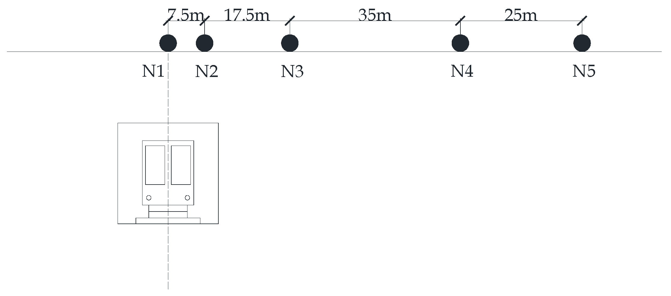
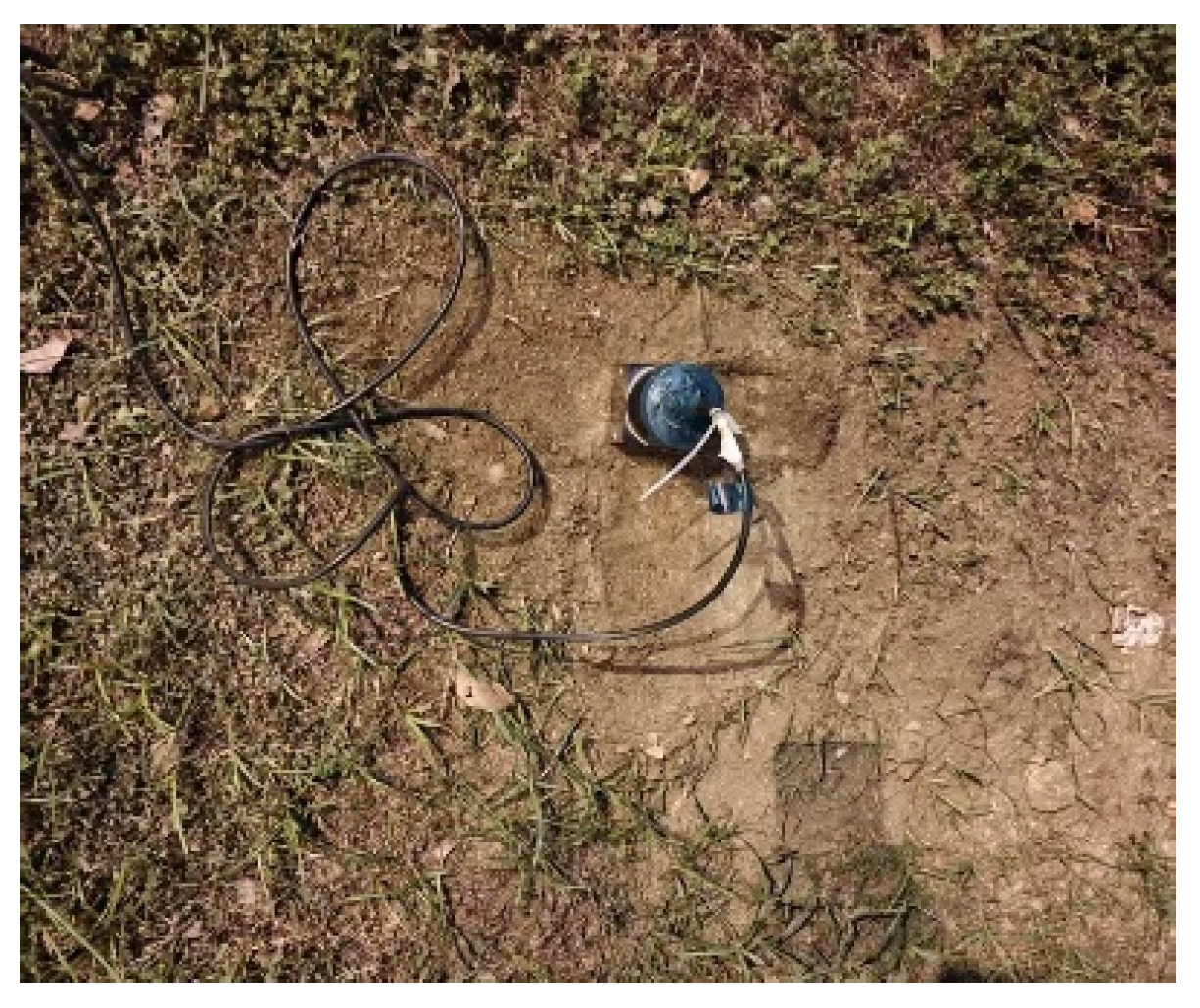
To validate the accuracy of the proposed finite element approach, field measurements of ground vibrations induced by a metro line were conducted. The layout of the measurement points is shown in Figure 4. During the field tests, loose soil and surface debris were removed before installing the vibration sensors. The ground surface was then compacted to ensure firm contact, and all sensors were placed horizontally. The arrangement of the vibration sensors is illustrated in Figure 5. After multiple train passages were measured, the vertical ground vibration responses were obtained. The Z-vibration level V L Z (where Z denotes the vertical direction, with a reference acceleration of 1 × 10⁻⁶ m/s2), corresponding to each train passage, was calculated from the measured acceleration time histories. The arithmetic mean of the vibration levels obtained from multiple measurements was adopted as the evaluation index.
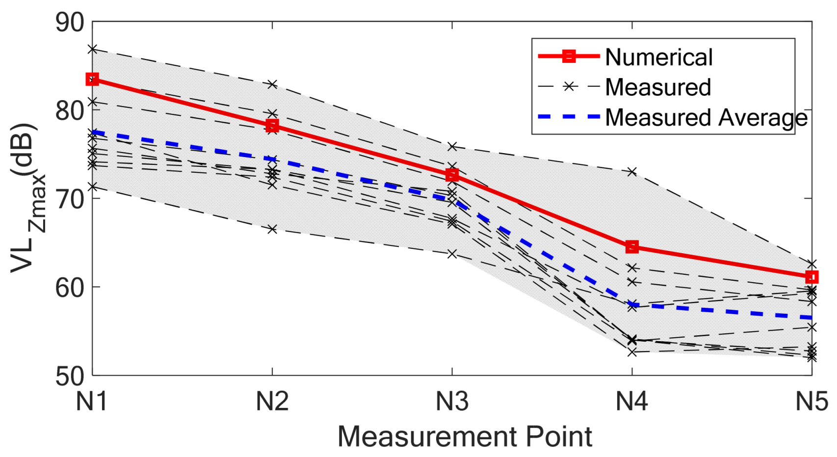
Based on the numerical element approach for predicting railway-induced ground vibrations described above, numerical simulations were carried out to predict the ground vibrations induced by metro train operations. The comparison between the numerical predictions and the field measurements is presented in Figure 6, while the relative errors between the numerical results and the measured average values are summarized in Table 1. As shown in Figure 6, all numerical predictions fall within the envelope of the measured data. Compared with the averaged field measurements, the relative errors are all below 15%, with most measurement points exhibiting errors of less than 10%. Furthermore, the numerical and measured results exhibit similar attenuation trends. The numerical predictions are generally slightly higher than the measured average values. This discrepancy may be attributed to the inability of the finite element model to fully capture the spatial variability of soil properties, as well as the conservative assumptions adopted in the numerical analysis. Overall, the comparison demonstrates that the proposed finite element approach can accurately predict railway-induced ground vibrations with satisfactory reliability, providing a solid foundation for the subsequent analyses presented in this study.

3. Propagation Characteristics of Ground-Borne Vibrations

3.1. Propagation Characteristics

Train-induced vibrations originate at the wheel–rail interface and propagate through the surrounding soil in the form of elastic waves. Consequently, the mechanical properties of the soil are among the primary factors governing the ground vibration response. This section investigates the propagation characteristics of ground-borne vibrations in homogeneous soils with different stiffnesses. To represent different soil conditions, the tunnel burial depth h was fixed at 15 m, and five numerical cases with different elastic moduli were considered. The material properties adopted for each case are summarized in Table 2.
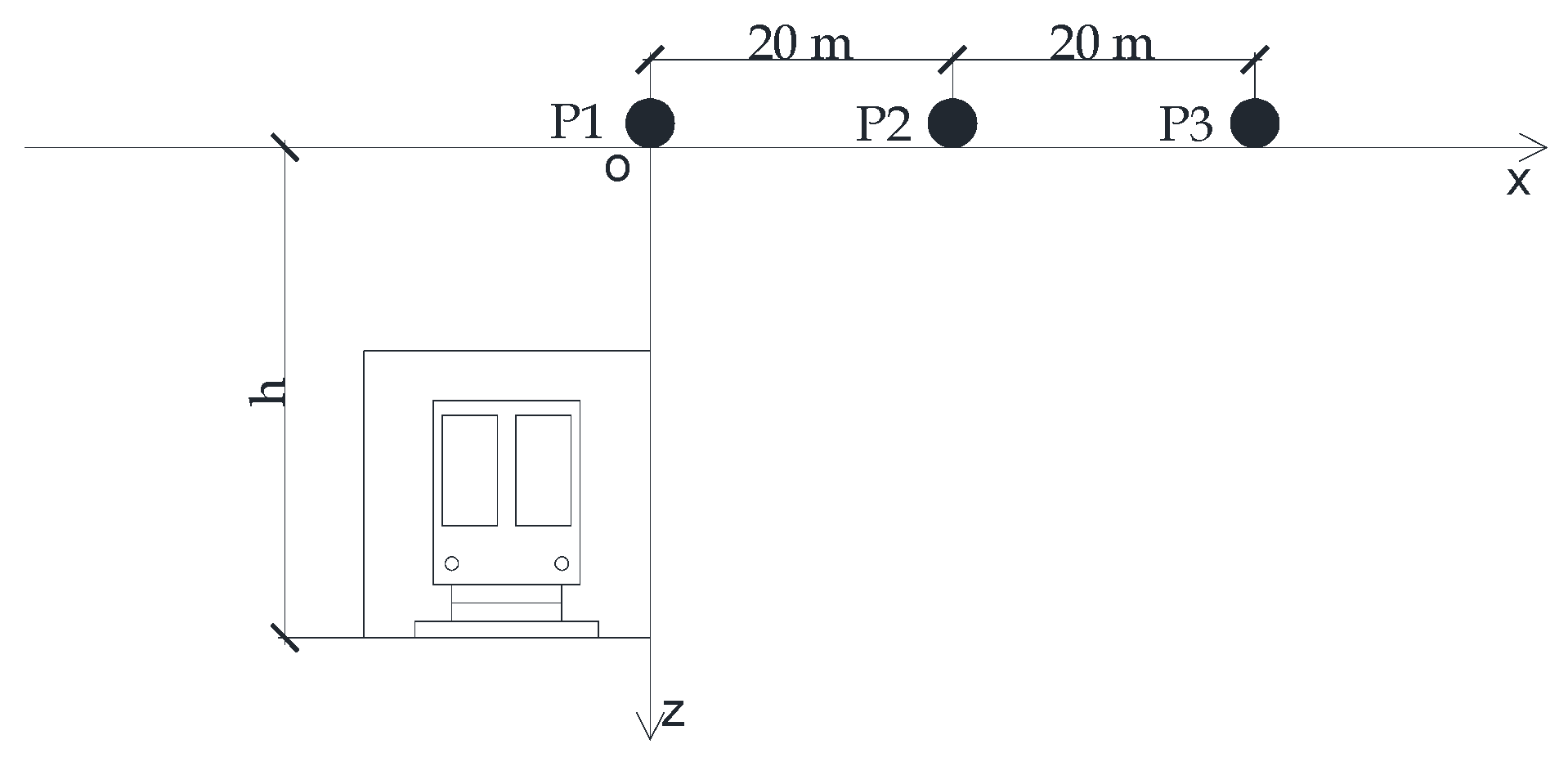
To evaluate the propagation characteristics of ground vibrations, acceleration monitoring points were arranged at intervals of 2 m along both the ground surface and a horizontal plane located 10 m below the ground surface. Three representative monitoring points (P1–P3) were selected on the ground surface along the vibration propagation direction for frequency-domain analysis, as illustrated in Figure 7. The adjacent points were spaced 20 m apart, representing different propagation distances and enabling the evaluation of vibration attenuation and frequency-dependent propagation characteristics.
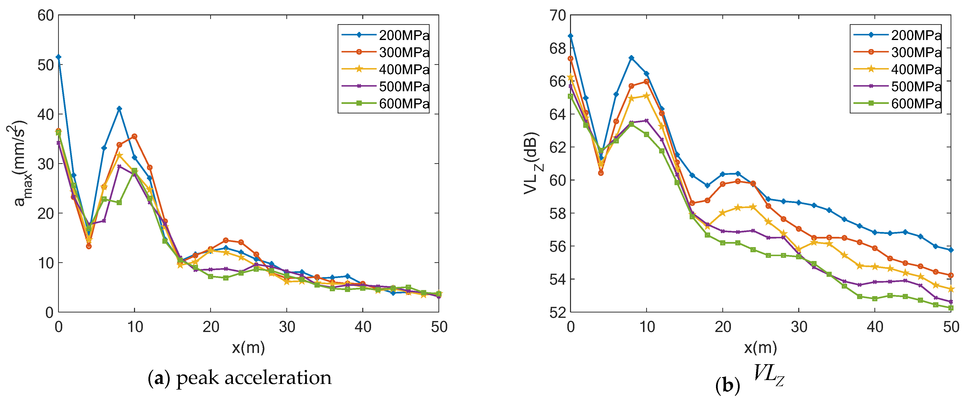
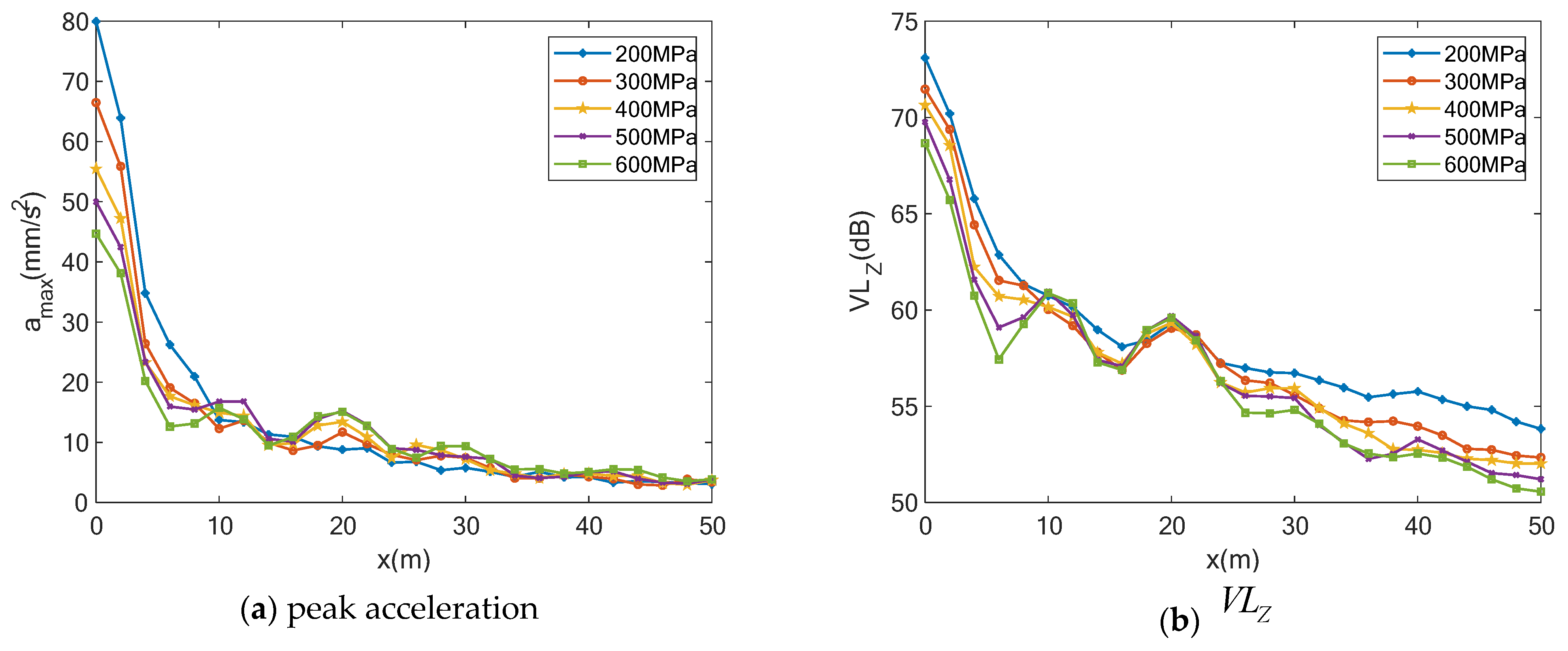
The finite element simulations yielded the distributions of peak acceleration and V L Z at the ground surface, as shown in Figure 8, while the corresponding results at a depth of 10 m are presented in Figure 9. Comparison of the vibration responses at different distances indicates that a pronounced vibration amplification zone appears on the ground surface approximately 4 m from the vibration source. Beyond a propagation distance of approximately 20 m, the vibration response exhibits an oscillatory attenuation pattern, accompanied by several local amplification zones with considerably smaller amplitudes. In contrast, no obvious primary amplification zone is observed at a depth of 10 m; instead, only relatively weak periodic amplification zones appear during wave propagation. Comparison among the five soil conditions further reveals that the overall vibration response decreases with increasing soil stiffness. For example, at x = 0 m, the V L Z decreases by approximately 0.5–1.5 dB for every 100 MPa increase in the soil elastic modulus.
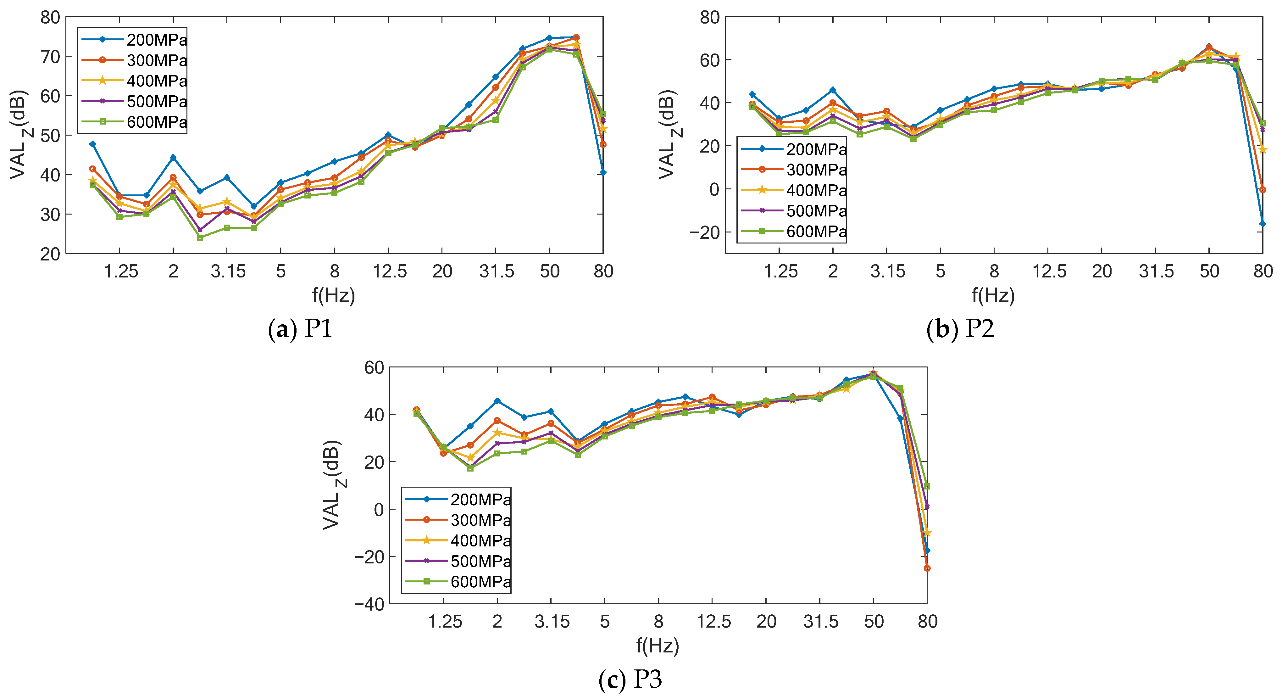
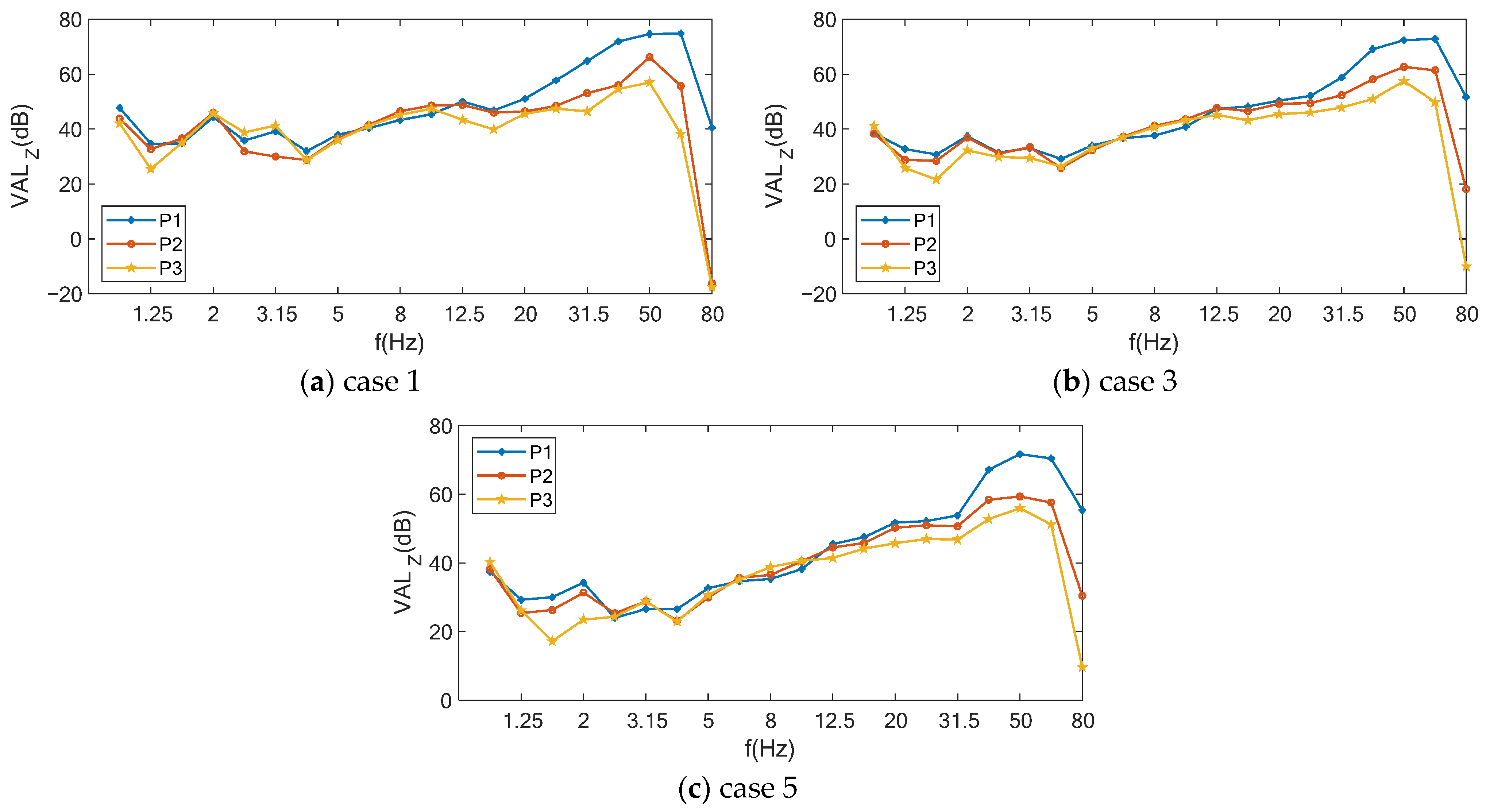
To further investigate the influence of soil stiffness on the frequency characteristics of ground vibrations, one-third-octave-band analyses were performed for monitoring points P1, P2, and P3. The corresponding frequency spectra for different soil conditions are shown in Figure 10 and Figure 11. As shown in figures, increasing the soil elastic modulus leads to a gradual increase in the proportion of high-frequency (>20 Hz) vibration components, while the low-frequency components (<20 Hz) become less dominant. High-frequency vibrations attenuate rapidly with propagation distance, whereas low-frequency vibrations exhibit much slower attenuation. Furthermore, comparison of the one-third-octave-band vibration levels at P1–P3 indicates that vibration amplification occurs predominantly in the low-frequency range, whereas high-frequency vibrations mainly undergo continuous attenuation during propagation. Consequently, vibration amplification is more pronounced in softer soils with lower elastic moduli. For example, in Case 3, the vibration level in the 50 Hz one-third-octave band decreases successively by 9.7 dB and 5.2 dB as the vibration propagates from P1 to P3. In contrast, for the 5 Hz frequency band, the vibration level first decreases by 1.7 dB and subsequently increases by 0.6 dB, demonstrating the occurrence of vibration amplification in the low-frequency range.

3.2. Theoretical Analysis

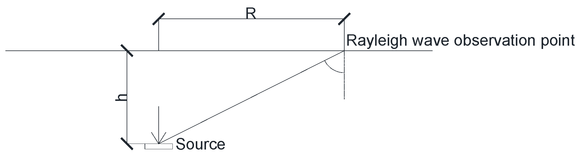
Elastic-wave propagation in soils consists of body waves and surface waves, including compressional (P) waves, shear (S) waves, and Rayleigh waves. S waves propagate with particle motion perpendicular to the direction of wave propagation and can be further classified into SH waves, with particle motion parallel to the ground surface, and SV waves, with particle motion in the vertical plane. In contrast, P waves propagate with particle motion parallel to the propagation direction. When a P wave impinges on a free surface at an angle greater than the critical angle, interaction between the reflected P wave and the converted SV wave generates a Rayleigh wave, as illustrated in Figure 12. The critical angle satisfies
sin θ c = c R c P
where c R and c P denote the velocities of the Rayleigh wave and the P wave, respectively.
For a vibration source buried at a depth h, the horizontal distance from the source at which a Rayleigh wave can first be observed is denoted by R. According to geometric relationships, the critical angle θ c satisfies:
tan θ c = R h
Combining Equations (1) and (2), the existence of Rayleigh waves on the ground surface requires
R > c R h c P 2 c R 2
For a homogeneous elastic medium, the propagation velocities of the three wave types satisfy
c P = E 1 ν ρ 1 + ν 1 2 ν
c S = E 2 ρ 1 + ν
2 c R 2 c S 2 2 4 1 c R 2 c P 2 1 c R 2 c S 2 = 0
Substituting the material parameters of the five numerical cases into Equations (3)–(6) yields a minimum observable Rayleigh-wave distance of approximately 7.54 m.
Considering that the rail centerline is located 3.15 m from the coordinate origin, the first vibration amplification zone on the ground surface appears approximately 7 m from the vibration source, which agrees well with the theoretical Rayleigh-wave generation distance. In contrast, no corresponding amplification zone is observed at a depth of 10 m, indicating that the first surface amplification zone is closely associated with the generation of Rayleigh waves.
Neglecting material damping and considering only geometric attenuation, the displacement amplitudes of P waves, S waves, and Rayleigh waves can be approximately expressed as
u p = A P r cos k P r ω t
u S = A S r cos k S r ω t
u R = A R r cos k R r ω t
where u P , u S and u R denote the amplitudes of the P wave, S wave, and the vertical component of the Rayleigh wave at the ground surface, respectively; A P , A S and A R are the corresponding initial amplitudes; k P , k S and k R represent the wave numbers; r is the propagation distance; ω is the angular frequency; and t denotes time.
Equations (7)–(9) indicate that the amplitude of each individual wave decreases continuously with increasing propagation distance. However, differences in wave number produce phase shifts relative to the vibration source, which can be expressed as
ϕ P , i = ω i r c P = k P , i r
ϕ S , i = ω i r c S = k S , i r
ϕ R , i = ω i r c R = k R , i r
where ϕ denotes the phase difference corresponding to the i-th angular frequency.
Constructive interference occurs when two wave components satisfy
Δ ϕ = ϕ X , i ϕ Y , j = k X , i k Y , j r = 2 n π
where the subscripts X and Y denote the wave types, which may represent P waves, S waves, or Rayleigh waves; the subscripts i and j denote the indices of the angular-frequency components. Where at least one of the conditions X Y and i j is satisfied, and n is an arbitrary integer.
Under this condition, constructive interference occurs, resulting in the formation of a vibration amplification zone. Since the phase relationships among different wave components vary periodically during wave propagation, vibration amplification zones also appear periodically.
Consequently, the multiple amplification zones observed on the ground surface are attributed to the constructive interference of P waves, S waves, and Rayleigh waves with different frequency components. In contrast, the amplification zones observed within the soil are primarily caused by the constructive interference between P waves and S waves, owing to the absence of Rayleigh-wave propagation beneath the free surface.
Furthermore, to investigate the variation in the spacing between vibration amplification zones under different soil conditions, the superposition of P waves and S waves at a specific frequency ω 0 is considered as an example. The minimum spacing between adjacent vibration amplification zones, r min , can be derived as follows:
r min = 2 π ω 0 c P c S c S c P
This expression indicates that r min increases with increasing soil elastic modulus, which agrees well with the finite element results.

4. Analysis of Vibration Isolation Performance of Infilled Trenches

A commonly adopted approach for mitigating railway-induced ground vibration is to install vibration isolation barriers along the propagation path, among which infilled trenches are widely used. Previous studies have demonstrated that the isolation performance of in-filled trenches is primarily governed by the trench geometry and the mechanical properties of filling materials [26,27]. Among these parameters, trench depth determines the effective barrier height relative to the propagating waves, while the filling material affects wave reflection and transmission due to differences in stiffness and damping characteristics. Therefore, this study focuses on trench depth and filling material as two representative parameters to reveal the fundamental mechanisms of vibration isolation.
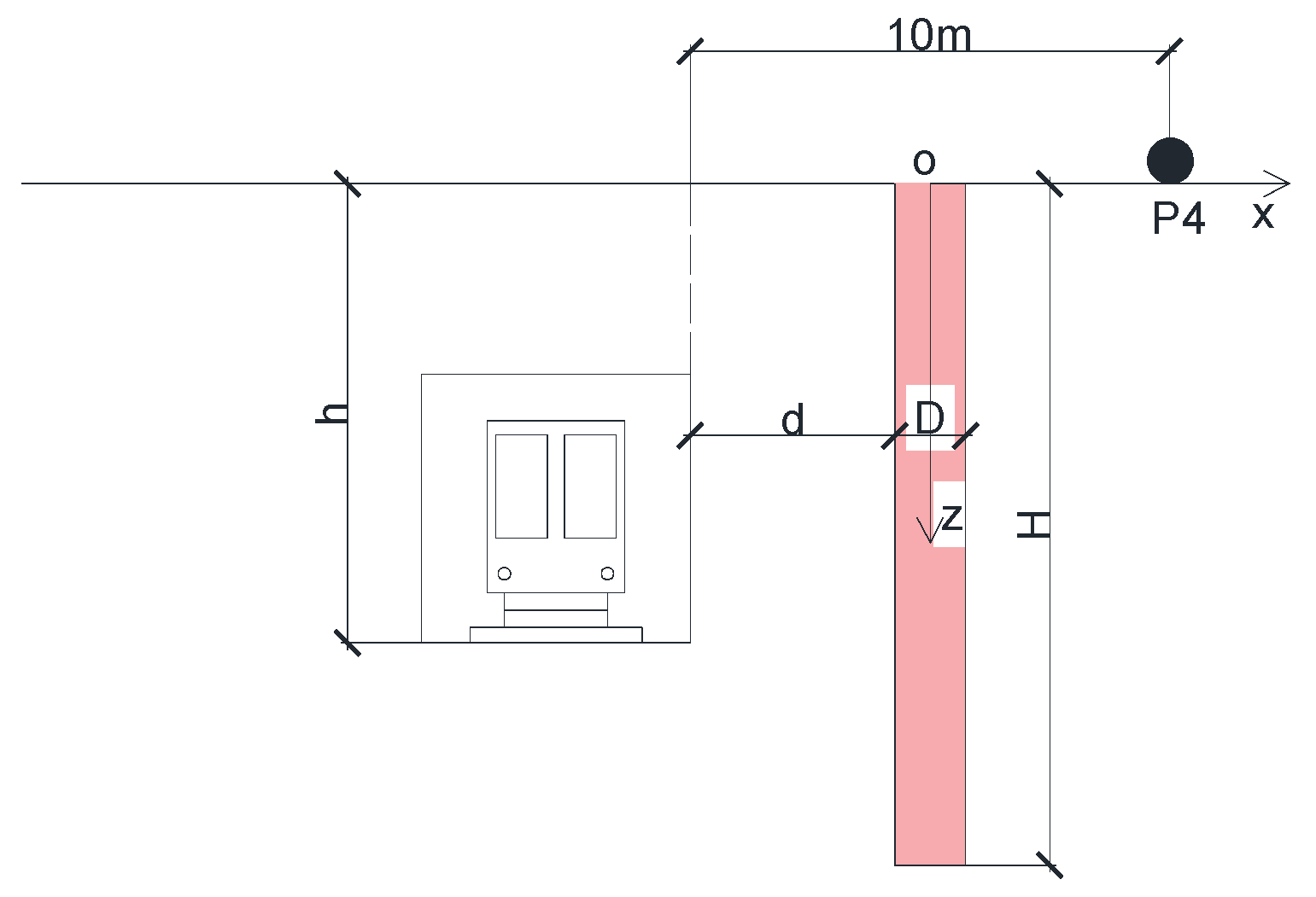
The geometric relationship between the infilled trench and the tunnel is illustrated in Figure 13, where d donates the horizontal distance between the trench wall and the tunnel wall, h is the tunnel burial depth, H is the trench depth, and D is the trench width.
Infilled trench materials can generally be classified into two categories according to their wave-impedance ratio with respect to the surrounding soil: flexible materials with a wave-impedance ratio less than 1 and rigid materials with a wave-impedance ratio greater than 1 [28]. To investigate the influence of different filling materials on vibration isolation performance, expanded polystyrene foam and concrete were selected as representative flexible and rigid materials, respectively. Based on the soil parameters listed in Table 2, finite element models incorporating the two types of infilled trenches were established for the five soil conditions. The tunnel burial depth was fixed at 15 m, the horizontal distance between the tunnel wall and trench wall was 5 m, the trench length was 15 m, and the trench width was 2 m. The trench depth was gradually increased from 5 m to 25 m to compare the vibration isolation performance of the two trench types under different soil conditions. The material properties are listed in Table 3, respectively.
The calculated wheel–rail excitation time history was applied to the track nodes to evaluate the vibration isolation performance of the infilled trenches under different conditions. To quantitatively assess the isolation effectiveness, the insertion loss (IL) was adopted as the evaluation index to characterize the spatial distribution of vibration reduction after trench installation. A positive value of IL (IL > 0) indicates that the trench provides vibration attenuation, whereas a negative value (IL < 0) represents vibration amplification caused by the isolation measure.
The insertion loss is calculated as
I L = V L Z 0 V L Z 1
where V L Z 0 and V L Z 1 represent the Z-vibration level before and after the installation of the vibration isolation trench, respectively.

4.1. Overall Analysis

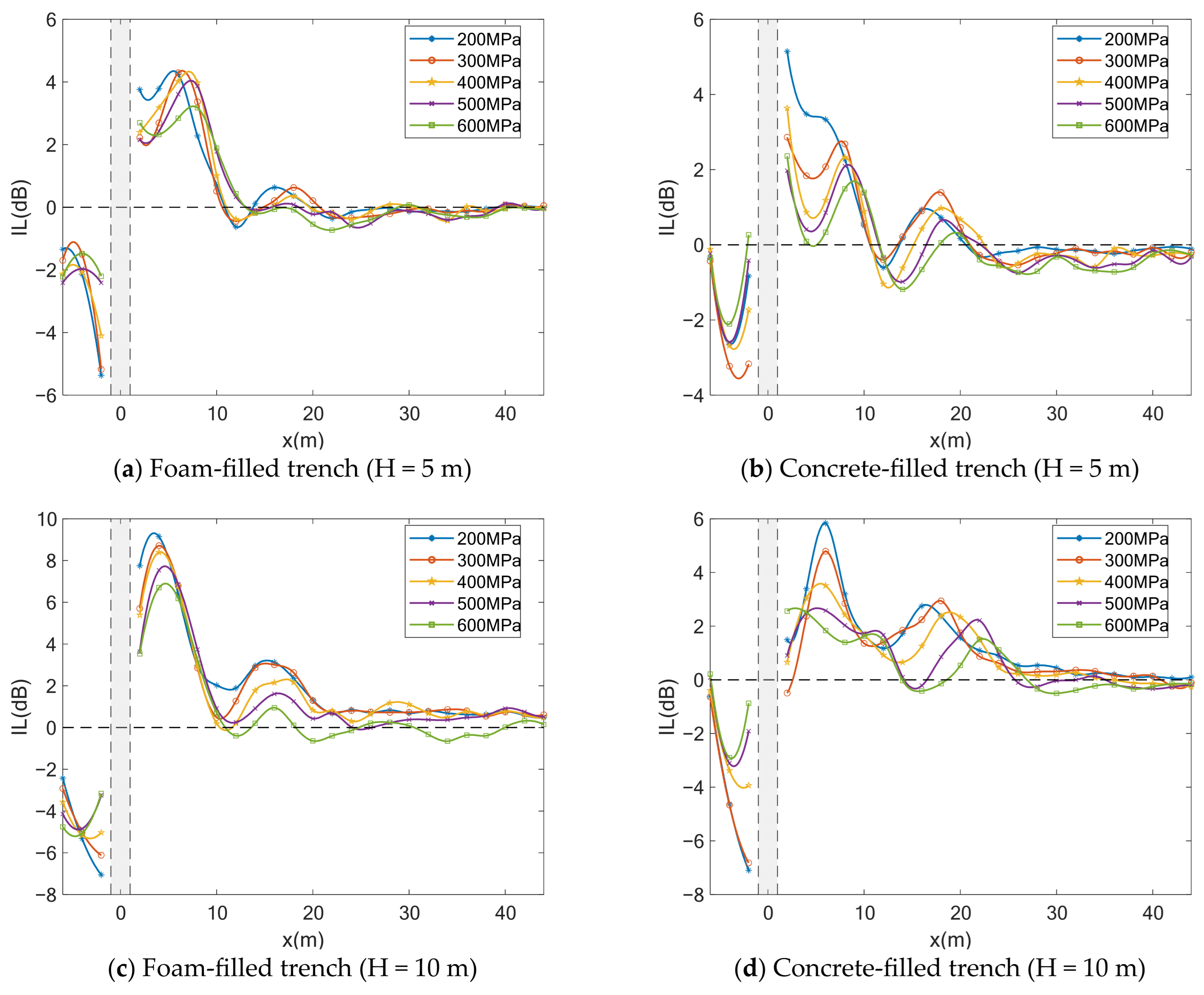
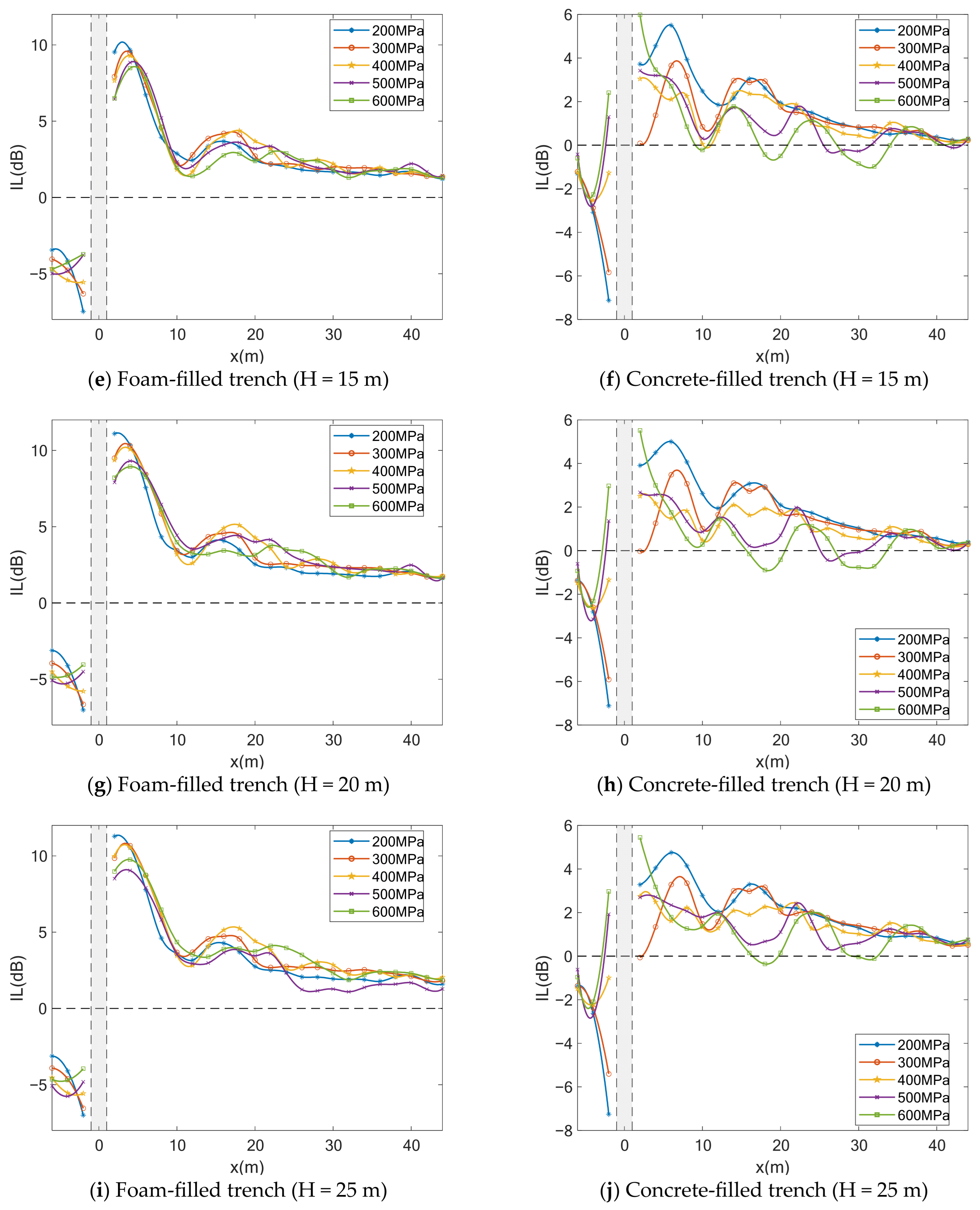
To investigate the spatial distribution of vibration isolation effectiveness along the x-direction after the installation of infilled trenches, a series of monitoring points were arranged along x-axis shown in Figure 13. Based on the numerical simulation results, the vibration isolation performance of the two types of infilled trenches with different depths under all working conditions is presented in Figure 14. The x-coordinate range occupied by the trench is highlighted by the gray-shaded region. Following the conventional terminology, the region between the vibration source and the trench is referred to as the front of the trench, whereas the region on the opposite side is referred to as the rear of the trench.
As shown in Figure 14, vibration amplification occurs to some extent in front of the trench. However, for the concrete-filled trench, positive insertion loss (IL > 0) is observed at certain locations in front of the trench when the soil elastic modulus is relatively high. In contrast, the vibration level behind the foam-filled trench is significantly reduced, indicating that the foam-filled trench provides satisfactory vibration isolation under all soil conditions. The vibration isolation performance of the concrete-filled trench is considerably inferior to that of the foam-filled trench, and under stiffer soil conditions, the vibration response behind the trench is even amplified. Furthermore, the insertion loss gradually decreases with increasing distance from the trench while exhibiting a fluctuating trend. This indicates that the vibration isolation effectiveness diminishes with propagation distance, and the fluctuation is closely associated with the wave interference mechanism discussed in the previous section. A comparison of trenches with different depths further shows that, when the trench depth is smaller than the tunnel burial depth (15 m), increasing the trench depth substantially improves the isolation performance of the foam-filled trench. As the trench depth increases from 5 m to 15 m, the maximum insertion loss increases successively by approximately 6 dB and 2 dB. Once the trench depth exceeds the tunnel burial depth, further increasing the depth produces little additional improvement. By contrast, increasing the depth of the concrete-filled trench does not noticeably enhance its vibration isolation performance.
Overall, the foam-filled trench exhibits excellent vibration isolation capability, whereas the concrete-filled trench provides limited vibration reduction and may induce local vibration amplification behind the trench due to wave reflection effects. Considering both vibration mitigation performance and construction cost, the trench depth should be designed to be slightly greater than the burial depth of the vibration source. Previous studies have demonstrated that the mechanical properties of filling materials play an important role in determining the isolation performance of trenches. For example, reference [29] found that the elastic modulus of lightweight filling materials was the dominant factor affecting the load reduction efficiency of imperfect trench installations. This finding is consistent with the present results, where EPS-filled trenches exhibited improved vibration attenuation due to their low stiffness and impedance mismatch with the surrounding soil. The effectiveness of rigid fillings depends on the excitation characteristics and wave propagation conditions. A recent study [30] reported that rigid material-filled trenches could effectively reduce structural responses under point and earthquake excitations. However, the present study focuses on metro-induced ground vibrations, which differ significantly from seismic excitations in terms of frequency characteristics and vibration mechanisms. The observed differences in concrete-filled trench performance may therefore be attributed to the different loading conditions and evaluation objectives. In this study, the local amplification behind the trench can be interpreted in terms of elastic wave reflection and interference effects.

4.2. Frequency-Domain Analysis

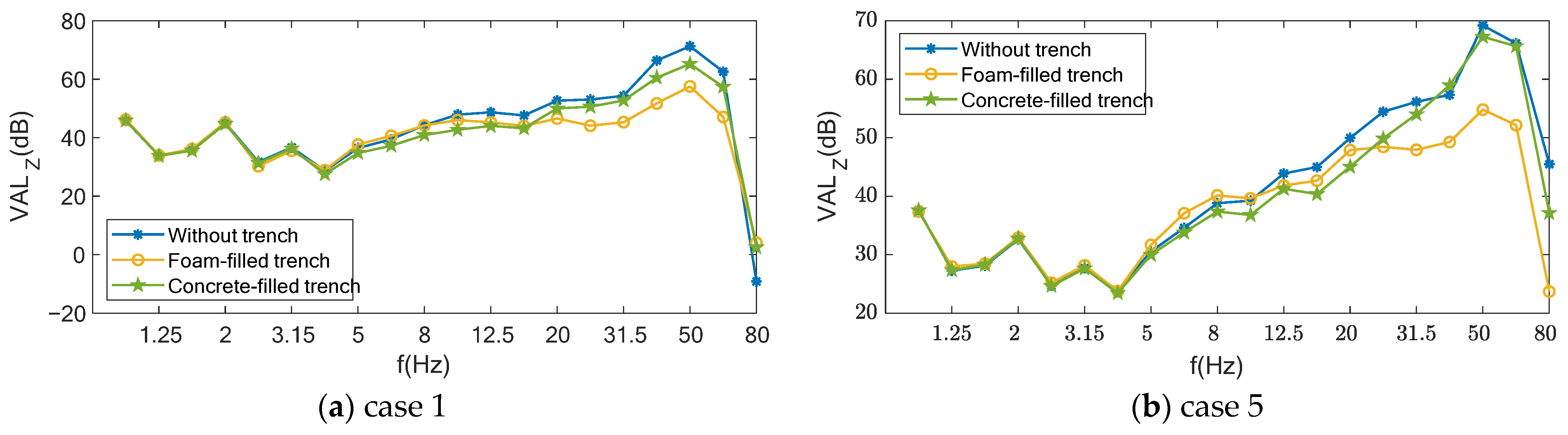
To investigate the frequency-dependent characteristics of the vibration isolation performance under different working conditions, monitoring point P4, as illustrated in Figure 13, was selected as a representative point behind the trench to evaluate the frequency-dependent vibration isolation performance. When the trench depth is H = 20 m, the one-third octave vibration acceleration levels at monitoring point P4 before and after the installation of the trench for representative cases are presented in Figure 15.
As shown in Figure 15, for low-frequency vibrations below 5 Hz, the vibration levels change only slightly after the installation of the trench under all working conditions, indicating that the vibration isolation effectiveness of infilled trenches is limited in the low-frequency range (<20 Hz). This is mainly because low-frequency waves possess relatively long wavelengths and can readily propagate around the trench through diffraction. For frequencies above 5 Hz, the vibration levels decrease to varying degrees after the installation of the trench under all working conditions. Moreover, the foam-filled trench provides significantly better attenuation of high-frequency vibrations than the concrete-filled trench.
Combined with the previous analysis, it can be concluded that the proportion of high-frequency components increases with increasing soil elastic modulus. Since infilled trenches are more effective in attenuating high-frequency vibrations, their vibration isolation performance is correspondingly enhanced in stiffer soils. Consequently, the foam-filled trench consistently exhibits superior vibration isolation performance under all soil conditions, whereas the concrete-filled trench shows limited effectiveness and may even amplify the vibration response in certain frequency bands.

5. Conclusions

In this study, a numerical simulation approach was employed to investigate the propagation characteristics of railway-induced ground vibration in different soil conditions, as well as the vibration isolation performance and distribution characteristics of infilled trenches. The main conclusions are summarized as follows:
(1)
Ground vibration exhibits a fluctuating attenuation pattern during propagation, accompanied by multiple vibration amplification zones. A pronounced vibration amplification zone is observed on the ground surface.
(2)
During ground vibration propagation, high-frequency components attenuate more rapidly than low-frequency components. As the soil elastic modulus increases, the proportion of high-frequency vibration components increases, resulting in lower overall ground vibration levels in stiffer soils.
(3)
The first prominent surface vibration amplification zone is primarily induced by Rayleigh waves. The fundamental mechanism of vibration amplification is the phase difference generated by differences in the wave numbers of elastic waves during propagation, leading to constructive interference and the formation of new wave peaks.
(4)
The installation of infilled trenches can effectively reduce the vibration response behind the trench to a certain extent, with significantly better isolation performance for high-frequency vibrations. To achieve satisfactory vibration isolation while maintaining economic efficiency, the trench depth should be designed to be slightly greater than the burial depth of the vibration source. The results indicate that EPS-filled trenches generally provide better vibration reduction performance than concrete-filled trenches under the investigated metro vibration conditions. However, concrete-filled trenches may still achieve certain vibration mitigation effects in relatively soft soils with a low elastic modulus, although their performance remains inferior to EPS-filled trenches. The effectiveness of rigidly filled trenches depends on the soil properties, wave propagation characteristics, and excitation conditions. Furthermore, practical implementation of EPS-filled trenches requires consideration of construction feasibility, cost, and long-term durability. Meanwhile, underground structures such as diaphragm walls, which are primarily constructed for basement retaining and excavation support, may also provide additional vibration mitigation effects due to their wave-blocking characteristics.
It should be noted that a homogeneous linear elastic soil model was adopted in this study to focus on the fundamental influence of soil stiffness on vibration propagation mechanisms. Although actual ground conditions may involve layered strata, nonlinear behavior, groundwater effects, and spatial variability, these factors introduce additional complexity and may obscure the individual contribution of soil stiffness. Future studies will extend the proposed framework to more realistic geological conditions.

Author Contributions

Conceptualization, F.L. and G.Z.; methodology, F.L. and G.Z.; software, F.L. and G.Z.; validation, Z.Y. and G.Z.; formal analysis, Z.Y. and Z.S.; investigation, G.Z.; resources, F.L.; data curation, Z.Y.; writing—original draft preparation, Z.Y.; writing—review and editing, F.L.; visualization, F.L.; supervision, F.L. and G.Z.; project administration, F.L.; funding acquisition, F.L. All authors have read and agreed to the published version of the manuscript.

Funding

This research was funded by the National Key Research and Development Program of China (Grant No. 2024YFF0508102).

Data Availability Statement

The original contributions presented in this study are included in the article. Further inquiries can be directed to the corresponding author.

Conflicts of Interest

All authors were employed by the company China Academy of Building Research. Authors declare that the research was conducted in the absence of any commercial or financial relationships that could be construed as a potential conflict of interest.

References

  1. Connolly, D.P.; Marecki, G.P.; Kouroussis, G.; Thalassinakis, I.; Woodward, P.K. The growth of railway ground vibration problems—A review. Sci. Total Environ. 2016, 568, 1276–1282. [Google Scholar] [CrossRef] [Scilit] [PubMed]
  2. Lombaert, G.; Degrande, G.; Kogut, J.; François, S.; Thompson, D.J. Ground-borne vibration due to railway traffic: A review of excitation mechanisms, prediction methods and mitigation measures. Notes Numer. Fluid Mech. Multidiscip. Des. 2015, 126, 253–287. [Google Scholar] [CrossRef] [Scilit]
  3. Colaço, A.; Liravi, H.; Soares, P.J.; Ninić, J.; Costa, P.A. Ground-borne vibrations induced by railway traffic: Impact, prediction, mitigation and future perspectives. Vibration 2025, 8, 73. [Google Scholar] [CrossRef] [Scilit]
  4. Seidler, A.; Schubert, M.; Mehrjerdian, Y.; Krapf, K.; Popp, C.; Kamp, I.; Ögren, M.; Hegewald, J. Health effects of railway-induced vibration combined with railway noise—A systematic review with exposure-effect curves. Environ. Res. 2023, 233, 116480. [Google Scholar] [CrossRef] [Scilit]
  5. Shi, Y.; Dai, H.; Wang, Q.; Wei, L.; Shi, H. Research on low-frequency swaying mechanism of metro vehicles based on wheel-rail relationship. Shock Vib. 2020, 12, 8878020. [Google Scholar]
  6. Kouroussis, G.; Conti, C.; Verlinden, O. Investigating the influence of soil properties on railway traffic vibration using a numerical model. Veh. Syst. Dyn. 2013, 51, 421–442. [Google Scholar] [CrossRef] [Scilit]
  7. Liu, Z.; Ma, X.; Chi, J.; Chen, Y.; Wang, C. Centrifuge model tests and numerical simulation on ground-borne vibration propagating and vibration reduction scheme for tunnel inner structure. Tunn. Undergr. Space Technol. 2024, 153, 105996. [Google Scholar] [CrossRef] [Scilit]
  8. Wang, P.; Wei, K.; Wang, L.; Xiao, J. Experimental study of the frequency-domain characteristics of ground vibrations caused by a high-speed train running on non-ballasted track. Proc. Inst. Mech. Eng. Part F J. Rail Rapid Transit 2016, 230, 92–94. [Google Scholar] [CrossRef] [Scilit]
  9. Li, Z.; Yang, X.; Zhang, S.; Yu, Y.; Lin, Y.; Wu, J. Analysis of soil differences in subway vibration transmission paths. Buildings 2024, 14, 1338. [Google Scholar] [CrossRef] [Scilit]
  10. Zhao, L.; Yao, C.; Yan, Q.; Qian, K.; Yang, J.; Zhang, W. The effect of soil conditions on the dynamic response of shield tunnels under train-induced vibration loads. Geol. J. 2024, 59, 2690–2701. [Google Scholar] [CrossRef] [Scilit]
  11. Auersch, L. Site-Specific Amplitude-Distance Laws, Wave velocities, damping, and transfer functions of the soil from hammer impacts and application to railway-induced ground vibration: Similarities and mid-frequency differences. J. Vib. Eng. Technol. 2023, 11, 2671–2687. [Google Scholar] [CrossRef] [Scilit]
  12. Cao, Y.; Xiang, Q.; Li, B.; Li, Z. Field Measurement and energy analysis of ground-borne vibration around high-speed railway viaduct. Shock Vib. 2023, 20, 4640726. [Google Scholar]
  13. Bi, J.; Gao, G.; Chen, Z.; Zhang, J.; Chen, J.; Li, Y. Field measurement and 2.5D FE analysis of ground vibrations induced by high-speed train moving on embankment and cutting. Buildings 2025, 15, 4034. [Google Scholar] [CrossRef] [Scilit]
  14. Dai, F.; Yang, J.; Bi, L.; Liu, Y. Analysis on characteristics of ground vibration induced by underground high-speed trains based on in-situ test. J. Low Freq. Noise Vib. Act. Control 2024, 43, 1097–1111. [Google Scholar] [CrossRef] [Scilit]
  15. Feng, S.; Zhang, X.; Wang, L.; Zheng, Q.; Du, F.; Wang, Z. In situ experimental study on high speed train induced ground vibrations with the ballast-less track. Soil Dyn. Earthq. Eng. 2017, 102, 195–214. [Google Scholar] [CrossRef] [Scilit]
  16. Wang, L.; Wang, P.; Wei, K.; Dollevoet, R.; Li, Z. Ground vibration induced by high speed trains on an embankment with pile-board foundation: Modelling and validation with in situ tests. Transp. Geotech. 2022, 34, 100734. [Google Scholar] [CrossRef] [Scilit]
  17. Sheng, A.; Li, L.; Han, J.; Du, X. Characteristics of environmental vibration induced by trains in underground stacked platform station. Tunn. Undergr. Space Technol. 2026, 169, 107321. [Google Scholar] [CrossRef] [Scilit]
  18. Krylov, V.V. Focusing of ground vibrations generated by high-speed trains travelling at trans-Rayleigh speeds. Soil Dyn. Earthq. Eng. 2017, 100, 389–395. [Google Scholar] [CrossRef] [Scilit]
  19. Motazedian, D.; Hunter, J.A.; Sivathayalan, S.; Pugin, A.; Pullan, S.; Crow, H.; Khaheshi Banab, K. Railway train induced ground vibrations in a low VS soil layer overlying a high VS bedrock in eastern Canada. Soil Dyn. Earthq. Eng. 2012, 36, 1–11. [Google Scholar] [CrossRef] [Scilit]
  20. Yu, K.; Gu, X.; Huang, M.; Ma, X.; Li, N. Experimental, numerical and analytical studies on the attenuation of maglev train-induced vibrations with depth in layered soils. Soil Dyn. Earthq. Eng. 2021, 143, 106628. [Google Scholar] [CrossRef] [Scilit]
  21. Ouakka, S.; Verlinden, O.; Kouroussis, G. Railway ground vibration and mitigation measures: Benchmarking of best practices. Railw. Eng. Sci. 2022, 30, 1–22. [Google Scholar] [CrossRef] [Scilit]
  22. Çelebi, E.; Kırtel, O.; İstegün, B.; Göktepe, F.; Navdar, M.B.; Subaşı, A.; Zülfikar, A.C. Mitigation of high-speed train induced surface vibrations by open trench with aerated concrete panel walls. Constr. Build. Mater. 2023, 400, 132771. [Google Scholar] [CrossRef] [Scilit]
  23. Gao, L.; Cai, C.; Li, C.; Mak, C.M. Numerical analysis of the mitigation performance of a buried pt-wib on environmental vibration. Sensors 2023, 23, 7666. [Google Scholar] [CrossRef] [Scilit]
  24. Mhanna, M.; Sabaa, M.R.; Mahdi, H.A.; Karkush, M. Ground vibration isolation using mass scatters: A comparative study with trench barriers and wave-impeding blocks. Deep Undergr. Sci. Eng. 2025, 4, 792–799. [Google Scholar] [CrossRef] [Scilit]
  25. Jayawardana, P.; Thambiratnam, D.P.; Perera, N.; Chan, T. Dual in-filled trenches for vibration mitigation and their predictions using artificial neural network. Soil Dyn. Earthq. Eng. 2019, 122, 107–115. [Google Scholar] [CrossRef] [Scilit]
  26. Mazumdar, A.; Bhowmik, D. A Numerical Study of the Behavior of Sand–Crumb Rubber Mixture–Filled Trench for Active Vibration Isolation. Int. J. Geomech. 2025, 25, 04025023. [Google Scholar] [CrossRef] [Scilit]
  27. Yao, J.; Zhao, R.; Zhang, N.; Yang, D. Vibration isolation effect study of in-filled trench barriers to train-induced environmental vibrations. Soil Dyn. Earthq. Eng. 2019, 125, 105741. [Google Scholar] [CrossRef] [Scilit]
  28. Zhao, S.; Lu, C.; Shen, J.; Zhao, M. Train-Induced Vibration Analysis and Isolation Trench Measures in Metro Depot Structures. Appl. Sci. 2025, 15, 4219. [Google Scholar] [CrossRef] [Scilit]
  29. Kang, J.; Parker, F.; Yoo, C.H. Soil-Structure Interaction and Imperfect Trench Installations for Deeply Buried Concrete Pipes. J. Geotech. Geoenviron. Eng. 2007, 133, 277–285. [Google Scholar] [CrossRef] [Scilit]
  30. Rasa, A.Y.; Budak, A. Soil-structure-trench interaction effects on vibration isolation of multi-story structures. J. Braz. Soc. Mech. Sci. Eng. 2026, 48, 186. [Google Scholar] [CrossRef] [Scilit]
Figure 1. Schematic diagram of the vehicle–track coupled model.
Buildings 16 03412 g001
Figure 2. Vertical wheel–rail excitation time history.
Buildings 16 03412 g002
Figure 3. Three-dimensional finite element model of the tunnel–soil system.
Buildings 16 03412 g003
Figure 4. Layout of field measurement points.
Buildings 16 03412 g004
Figure 5. Arrangement of ground vibration sensors.
Buildings 16 03412 g005
Figure 6. Comparison of numerical simulation and field measurement results.
Buildings 16 03412 g006
Figure 7. Schematic diagram of measurement points.
Buildings 16 03412 g007
Figure 8. Variation in ground surface vibration in different soil conditions.
Buildings 16 03412 g008
Figure 9. Variation vibration at 10 m depth in different soil conditions.
Buildings 16 03412 g009
Figure 10. Frequency-dependent vibration levels at selected monitoring points in different soil conditions.
Buildings 16 03412 g010
Figure 11. Frequency-dependent vibration levels at selected monitoring points in the same soil condition.
Buildings 16 03412 g011
Figure 12. Schematic diagram of critical angle.
Buildings 16 03412 g012
Figure 13. Schematic layout of the infilled trench.
Buildings 16 03412 g013
Figure 14. Vibration isolation performance of infilled trenches along the x-direction.
Buildings 16 03412 g014aBuildings 16 03412 g014b
Figure 15. One-third octave vibration acceleration levels at monitoring point P4.
Buildings 16 03412 g015
Table 1. Comparison between numerical simulation and field measurement results.
N1N2N3N4N5
Measured results77.5274.4269.8058.0156.51
Numerical simulation results83.4678.2272.6464.5261.12
Relative errors8%5%4%11%8%
Table 2. Soil material properties.
CaseE/MPaρ/(kg/m3)ν
No.12002 × 1030.35
No.23002 × 1030.35
No.34002 × 1030.35
No.45002 × 1030.35
No.56002 × 1030.35
Table 3. Material properties of trench filling materials.
MaterialE/MPaρ/(m/s3)ν
expanded polystyrene foam11.8800.4
concrete39,00025000.2
Disclaimer/Publisher’s Note: The statements, opinions and data contained in all publications are solely those of the individual author(s) and contributor(s) and not of MDPI and/or the editor(s). MDPI and/or the editor(s) disclaim responsibility for any injury to people or property resulting from any ideas, methods, instructions or products referred to in the content.