Article

Behavior and Performance of CFRP-Confined Recycled Concrete Under Dynamic Impact Loading

1
School of Civil Engineering, Kashi University, Kashi 844000, China
2
Xinjiang Key Laboratory of Engineering Materials and Structural Safety, Kashi 844000, China
3
Department of Civil Engineering, Shandong Jianzhu University, Jinan 250101, China
4
The Key Laboratory of Urban Security and Disaster Engineering of the Ministry of Education, Beijing University of Technology, Beijing 100124, China
*
Author to whom correspondence should be addressed.
Buildings 2026, 16(12), 2455; https://doi.org/10.3390/buildings16122455
Submission received: 11 May 2026 / Revised: 9 June 2026 / Accepted: 16 June 2026 / Published: 21 June 2026
(This article belongs to the Section Building Structures)

Abstract

To investigate the dynamic impact performance of carbon fiber reinforced polymer (CFRP)-confined recycled concrete, this study designed four series comprising 80 specimens with parameters including strain rate, recycled coarse aggregate replacement ratio, and number of CFRP confinement layers. Split Hopkinson Pressure Bar (SHPB) impact tests were conducted to analyze the dynamic failure mode, stress–strain responses under dynamic loading, and variation in compressive strength of the CFRP-confined concrete specimens. Additionally, a modified Weibull statistical model and fractal theory were employed to analyze the dispersion characteristics of dynamic compressive strength. The results show that the dynamic compressive strength exhibits clear strain-rate sensitivity. The presence of CFRP confinement does not alter the fundamental shape of the stress–strain curves under different strain rates. The proposed modified Weibull statistical model accurately predicts the distribution of dynamic compressive strength at varying strain rates, with an average prediction error of 3.4% and a maximum error of 5.3%. Fractal dimension can quantitatively characterize the evolution trend and degree of crack-induced damage. Within the strain rate range of 52.85–138.42 s−1, the fractal dimension of unconfined ordinary concrete specimens increases from 1.647 to 2.138; for unconfined recycled concrete, it increases from 1.612 to 2.158. The fractal dimension for CFRP-confined ordinary concrete specimens increases from 1.524 to 1.938, and for CFRP-confined recycled concrete specimens, from 1.503 to 2.019. The fractal dimension increases with the increase of strain rate, reflecting a typical strain rate effect.

1. Introduction

With the rapid advancement of urbanization in China, billions of tons of natural aggregates are consumed annually for concrete production, while the demolition of old buildings generates vast amounts of construction waste. This has led to a series of issues such as resource exhaustion and environmental pollution. To alleviate these challenges, the utilization of recycled aggregates and recycled concrete has garnered considerable attention both domestically and internationally. Existing studies have shown that, compared with natural aggregate concrete, the incorporation of recycled coarse aggregates results in degraded concrete performance. When natural coarse aggregates are replaced by recycled coarse aggregates, both the compressive strength [1,2,3,4,5] and elastic modulus of the concrete tend to decrease [6,7,8,9], and the introduction of recycled aggregates also negatively affects the shrinkage behavior of the concrete [10]. The tensile mechanical behaviors of green composite concrete prepared by combining fine and coarse recycled glass aggregates with recycled concrete aggregates, including axial tensile and splitting tensile behaviors, are also significantly different from those of conventional concrete. The dual incorporation of recycled aggregates and recycled glass aggregates tends to generate more micropores and weak interfaces inside the concrete, substantially reducing the overall integrity of the matrix. As a result, the strength of extension, ultimate tensile strain, and crack resistance of concrete continuously deteriorate. In addition, the aggregate replacement ratio and the particle-size gradation of glass aggregates directly affect the tensile failure mode of concrete, causing earlier microcrack initiation, faster crack propagation, and more pronounced brittle tensile failure characteristics during the tensile process [11,12,13,14,15]. In addition to the basic mechanical and deformation properties of concrete, the incorporation of recycled aggregates also significantly affects the mechanical behavior of structural members. Reinforced concrete beams prepared with recycled concrete aggregates exhibit obvious degradation in both flexural and shear mechanical properties. Compared with natural aggregate concrete beams, recycled aggregate concrete beams show varying degrees of reduction in flexural stiffness, ultimate flexural capacity, and ductility. During bending, cracks develop more rapidly and become more concentrated, while deflection deformation at the serviceability stage increases significantly. Meanwhile, the pore defects of recycled aggregates and the weak interfacial transition zones substantially reduce the shear capacity of beams, weaken aggregate interlock and the shear contribution of diagonal cracks, make shear brittleness more pronounced, and significantly reduce deformation stability under loading [16,17,18,19,20].
To improve the physical and mechanical properties of recycled concrete, researchers have proposed various enhancement strategies, such as incorporating admixtures and fiber materials into the matrix. Akça et al. [21] found that increasing the fiber volume fraction improved the flexural and tensile strength of recycled concrete. Since fibers are inlaid within the matrix and fill the pore space, many other studies have also confirmed that the incorporation of fibers significantly enhances the mechanical performance of recycled concrete [22,23,24,25,26,27]. In addition to modifying the intrinsic properties of recycled concrete, composite methods—such as lateral confinement using different materials—have been employed to improve its strength and deformability. Among these, lateral confinement has proven to be one of the most effective measures. Numerous studies have demonstrated that FRP confinement can significantly enhance the performance of recycled concrete. Teng et al. [28] conducted axial compression tests on CFRP-confined recycled concrete and found that CFRP confinement could enhance concrete strength and offset the negative effects caused by recycled coarse aggregates. Xiao Jianzhuang et al. [29] investigated the axial compressive behavior of GFRP-confined recycled concrete cylinders, showing that GFRP confinement improved compressive strength by approximately 30% and significantly enhanced deformability. Wu Gang et al. [30] and Gao et al. [31] also studied the compressive performance of FRP-confined concrete cylinders, concluding that FRP confinement greatly improves both strength and ductility. Zeng Lan et al. [32] analyzed the axial compression behavior of GFRP–recycled concrete–steel tube composite columns through monotonic axial loading tests and found that the novel composite columns demonstrated good ductility and seismic resistance. Particularly, double-tube composite components with a 30% recycled aggregate replacement ratio exhibited excellent mechanical performance.
In practical engineering applications, concrete structures are subjected not only to static loads but also to dynamic actions such as earthquakes, explosions, and impacts. These dynamic effects lead to distinct differences in the mechanical behavior and failure modes of concrete compared to static conditions, prompting extensive research into the dynamic mechanical properties of concrete.
However, the behavior of concrete under low- and high-strain-rate impact loads differs significantly. Xiao Jianzhuang et al. [33] and Bai Weifeng et al. [34] conducted axial compression tests on recycled concrete under low strain rates and found that both peak stress and elastic modulus increase with strain rate. In various engineering scenarios—such as vehicle collisions with bridge piers, aircraft landings, and missile attacks on protective structures—the structural safety under high strain-rate dynamic impacts must be considered. Wang Xiaojuan et al. [35] performed SHPB impact tests on recycled concrete and found that as the replacement ratio of recycled coarse aggregate increased, the dynamic strength variability of recycled concrete also increased. Li Yuexia et al. [36] investigated the impact mechanical properties of recycled concrete, showing a clear strain-rate enhancement effect, with dynamic peak stress exhibiting a linear relationship with strain rate. Mu Huiyu et al. [37] carried out SHPB tests under various impact air pressures on recycled concrete with different replacement ratios and found that both peak stress and peak strain were positively correlated with impact pressure and negatively correlated with replacement ratio. Teng Xiao et al. [38] conducted spalling tests on recycled concrete and observed that the spalling strength increased with rising impact velocity. These findings collectively indicate that recycled concrete exhibits pronounced strain-rate sensitivity, with strength increasing as impact rate increases. Htet et al. [39] conducted dynamic impact tests on hybrid fiber-reinforced recycled aggregate concrete and found that under high strain rates, the dynamic increase factor (DIF) of compressive strength for recycled concrete with 50% and 100% replacement ratios was higher than that of ordinary concrete. Wang et al. [40] conducted impact tests on high-ductility recycled aggregate concrete and demonstrated that fibers effectively restrained crack propagation and significantly reduced the brittleness of recycled aggregate concrete.
The Weibull model, proposed by Waloddi Weibull [41], is primarily used for analyzing the strength and lifetime data of materials. Based on this model, numerous scholars have conducted research on the damage characteristics of concrete. Tan et al. [42] performed a comparative study on the flexural fatigue behavior of steel fiber-reinforced recycled aggregate concrete (SFRAC), natural aggregate concrete (NAC), and recycled aggregate concrete (RAC). Their results showed that the fatigue life of NAC, RAC, and SFRAC followed a two-parameter Weibull distribution. Wang Qianfeng et al. [43] investigated the dynamic compressive behavior of concrete under various pore water pressures and loading rates, indicating that the damage behavior before the peak stress in the dynamic stress–strain curves follows a Weibull statistical distribution. Liang Hui et al. [44] developed a uniaxial compressive strain-rate-dependent constitutive model for concrete based on the Weibull statistical distribution theory. Wang Chunlai et al. [45] also used the Weibull statistical method to characterize and describe damage evolution in concrete under compression. Xie et al. [46] proposed a modified Weibull model that accurately predicted the damage probability distribution of the dynamic splitting tensile strength of concrete at different strain rates.
Fractal theory, originally proposed by Mandelbrot, essentially focuses on analyzing the characteristics of irregular and self-similar shapes and curves found in nature [47,48]. Based on this theory, researchers have investigated the impact damage behavior of concrete materials. Chen Meng et al. [49] examined the impact compressive properties of recycled tire polymer fiber (RTPF) concrete using fractal theory. Their findings showed that with increasing RTPF content, the fractal dimension of RTPF concrete first decreased and then increased, remaining consistently lower than that of fiber-free concrete. Quan et al. [50] explored the variation in compressive strength of recycled concrete under different fractal dimensions, and found that with the increase of fractal dimension, its compressive strength first increased and then decreased. Zhang et al. [51] applied fractal theory to analyze the impact fragmentation characteristics of steel fiber-reinforced recycled concrete, and found that with increasing recycled aggregate replacement ratio, the fractal dimension increased, while energy consumption exhibited a negative correlation with the fractal dimension. Xia et al. [52] conducted Split Hopkinson Pressure Bar (SHPB) tests on carbon nanofiber reinforced concrete, demonstrating that higher impact rates resulted in a greater number of smaller fragments, leading to higher fractal dimensions. Xu Jinyu et al. [53] studied the impact behavior of basalt fiber concrete after high-temperature exposure, showing that the energy dissipation density of the fractal feature increased with the fractal dimension.
Existing studies confirm that CFRP can significantly enhance the compressive strength and ductility of recycled concrete. However, up to now most studies both at home and abroad have mainly focused on the quasi-static mechanical behavior of CFRP-confined recycled concrete, while research on its behavior under dynamic impact loading remains relatively limited. In this study, the dynamic impact performance of CFRP-confined recycled concrete was investigated using a Split Hopkinson Pressure Bar (SHPB) apparatus. The influence of recycled coarse aggregate replacement ratios (0% and 100%) and CFRP confinement layers (0 and 1 layer) on the dynamic performance was analyzed. Additionally, the modified Weibull statistical model and fractal theory were employed to assess the probabilistic distribution of dynamic compressive strength and quantify impact-induced damage in CFRP-confined recycled concrete, aiming to provide theoretical support for engineering applications.

2. Experimental Overview

2.1. Raw Materials and Mix Proportion Design

The raw materials for the experiment include water, cement, sand, natural aggregates, and recycled aggregates. The water used is tap water, which conforms to JGJ 63-2022 Standard for Water Used in Concrete [54]. The cement is P.O. 42.5 grade cement produced by Shandong Jinan Shanshui Group, with a density of 3100 kg/m3 and a specific surface area of 350 m2/kg. The natural fine aggregate is river sand. The natural fine aggregate is river sand, and the normal aggregate (NA) is crushed stone with a particle size of 5–20 mm, while the recycled aggregate (RA) also has a particle size of 5–20 mm and is sourced from a demolished building in Beijing. The performance of the recycled aggregate meets the requirements of Recycled Aggregate for Concrete (GB/T 25177-2010) [55].
The mix proportion design for ordinary concrete was conducted in accordance with JGJ 55-2011 Code for Mix Design of Ordinary Concrete [56], with a design strength of C30. The final mix proportions of the experimental materials are shown in Table 1, where a coarse aggregate replacement rate of 0% represents ordinary concrete, and a replacement rate of 100% represents recycled concrete.

2.2. Specimen Design and Preparation

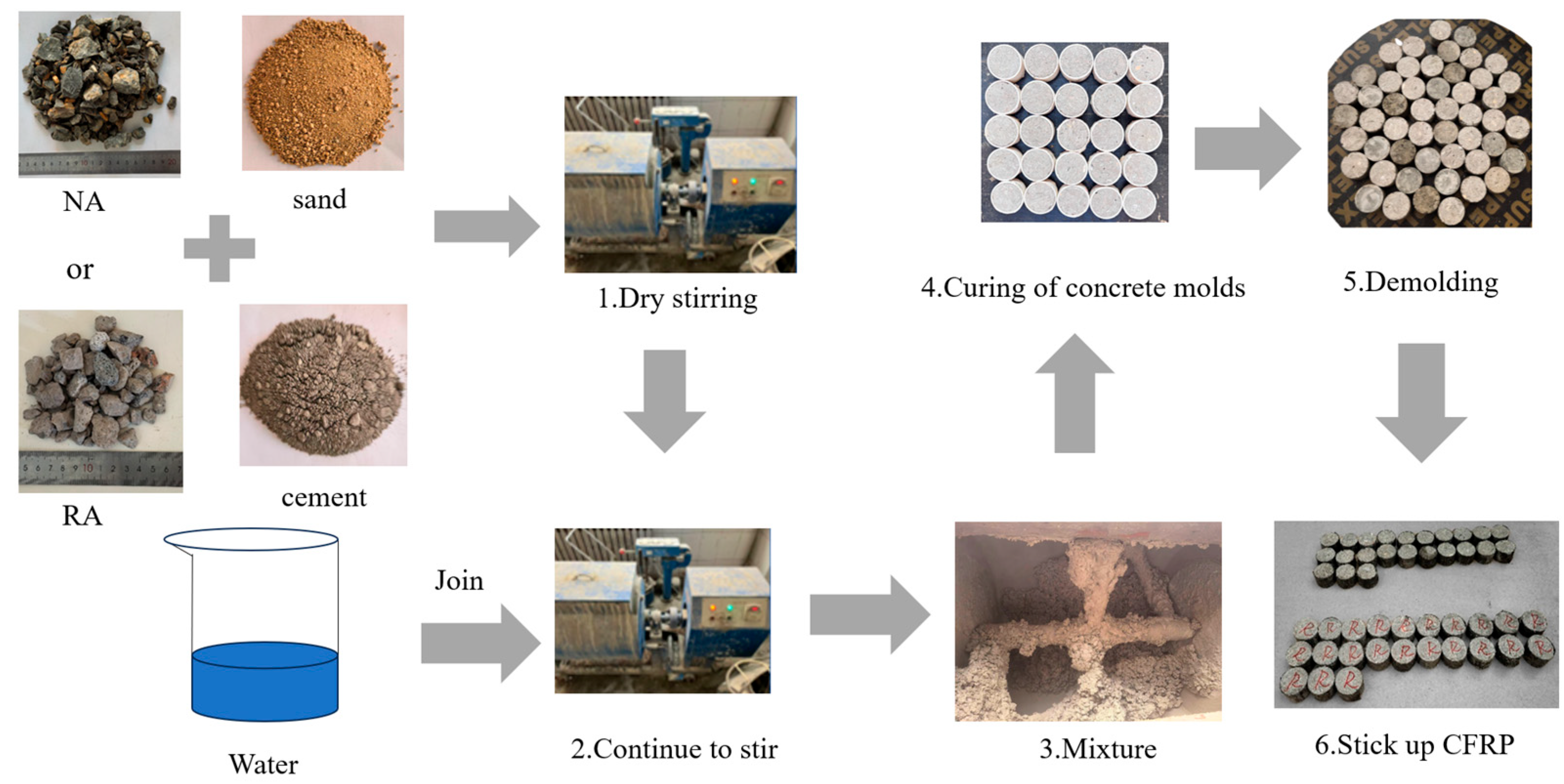
A total of 80 specimens were used for the dynamic impact test, divided into 16 groups with five specimens in each group. The specimen numbers and parameters are shown in Table 2. For the static compressive strength test, 12 specimens were prepared, grouped into four sets with three specimens per group. The specimens for the dynamic impact test are cylinders with dimensions of Φ50 mm × 25 mm, and those for the static compressive strength test are cylinders with dimensions of Φ150 mm × 300 mm. For the preparation of unconfined specimens, coarse aggregate and sand were first stirred for 120 s, then cement was added and stirred for another 120 s. Then, after adding water, continue to stir for 120 s. During the concrete production process, first, manual vibration with a vibration rod is carried out for 30 s. Then, the concrete is vibrated twice on the ZT1010 vibration table, each time for 30 s. Finally, the mixed concrete was cast into polyvinyl chloride (PVC) standard molds. After 24 h, the molds were removed, and the specimens were maintained for 28 days in an environment with a temperature of 20 °C and a relative humidity of 95%. After maintaining, the specimens were mechanically processed with a flat grinder to ensure their top and bottom surfaces were perfectly parallel and smooth. For confined concrete specimens, after the concrete specimens were demolded, their side surfaces were first cleaned and polished with a brush. Then, parts A and B of the epoxy resin were mixed evenly at a mass ratio of 2:1 and applied to the side surfaces of the cylindrical specimens. One layer of CFRP (carbon fiber reinforced polymer) was wrapped around the specimens, with an overlap at the joint to prevent premature failure. The specimen manufacturing and preparation process is shown in Figure 1. The properties of the CFRP fabric and the epoxy resin adhesive are shown in Table 3 and Table 4, respectively.

2.3. Loading Method

2.3.1. Quasi-Static Test

In accordance with Standard for Test Methods of Concrete Physical and Mechanical Properties (GB-T50081-2019) [57], quasi-static compression tests were conducted on cylindrical specimens of Φ150 mm × 300 mm. The tests adopted displacement loading at a rate of 0.18 mm/min until the specimens were completely destroyed. The compressive strength of each group was taken as the average value of the three specimens.

2.3.2. Dynamic Impact Test

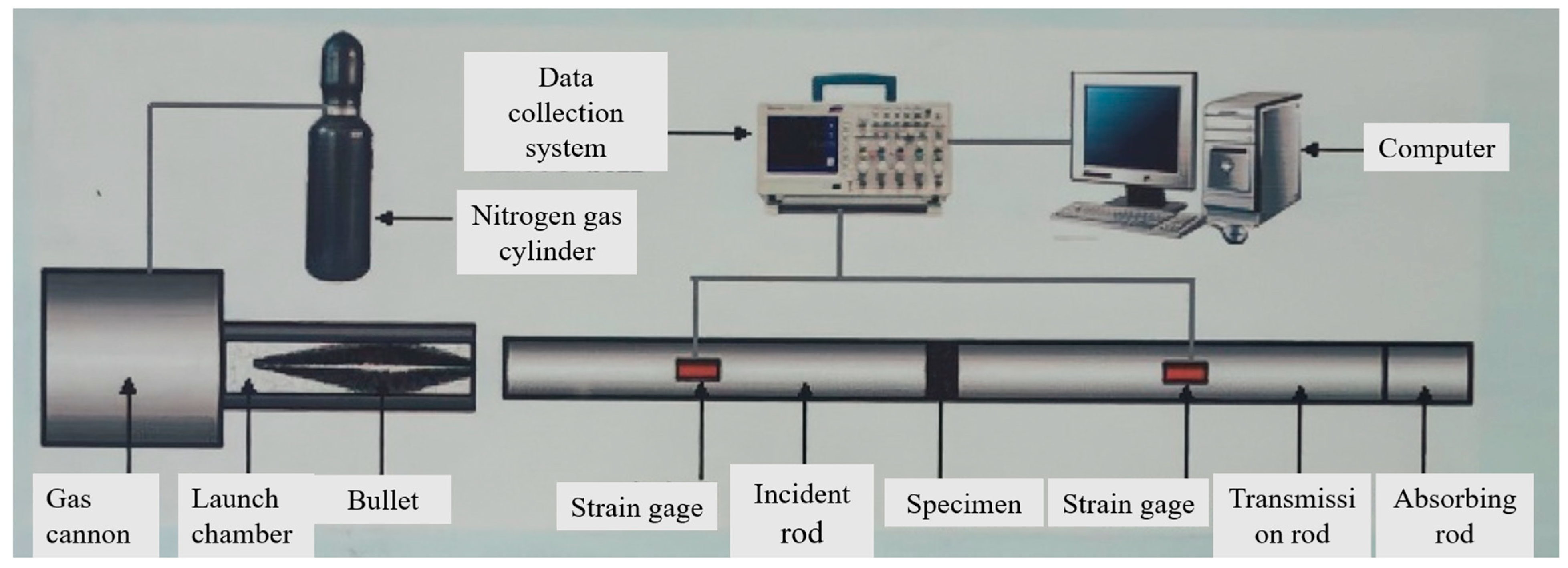
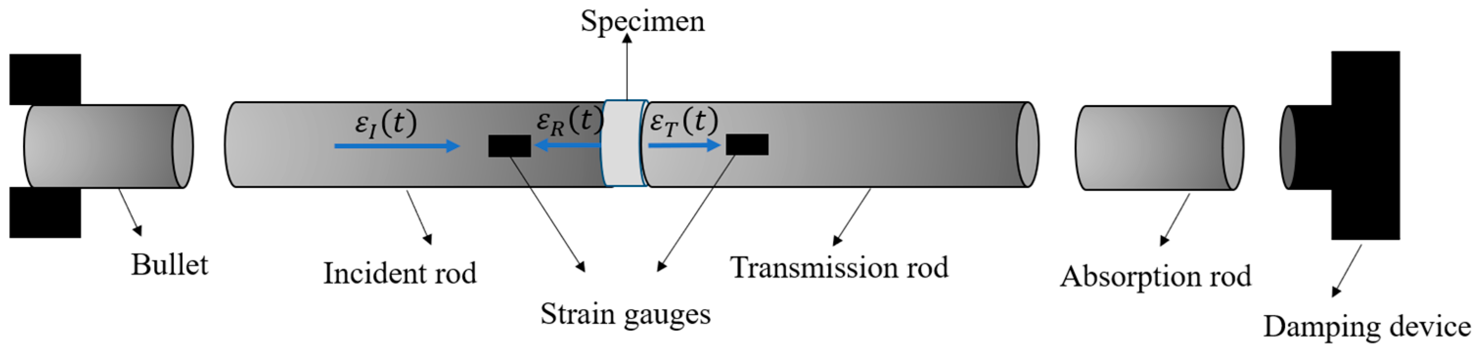
The Split Hopkinson Pressure Bar (SHPB) device used for the dynamic impact test is shown in Figure 2. It mainly consists of a nitrogen gas loading device, a bullet, a striker bar, an incident rod, a transmission rod, and a damping device. Figure 3 shows the propagation paths of the transmitted wave and reflected wave on the specimen and the bars.
The basic principle of the SHPB test is based on two fundamental assumptions: (1) Hypothesis of plane mechanism: During the propagation of the stress wave in the slender bar, each cross-section of the elastic bar remains a plane. (2) Stress uniformity assumption: The stress in the specimen is uniform everywhere during the round-trip propagation of the stress wave.
Different bullet velocities were achieved by changing the nitrogen gas air pressure, thus changing the strain rate. A circular H62 brass sheet with a diameter of 40 mm and a thickness of 1 mm was attached to the end face of the incident rod that was in contact with the bullet as a pulse shaper. This ensured the specimen had enough time to achieve stress uniformity and optimize the waveform. Vaseline was applied to the contact surfaces of the incident and transmission rods to reduce the effect of friction. During the dynamic impact test, four different impact air pressures were used to conduct the impact in a step-by-step manner to increase the impact rate.

3. Data Processing Methods

3.1. Stress–Strain Analysis (Three-Wave Method)

In an SHPB test, the reflected wave can be used to determine the strain rate. When a plateau appears in the peak section of the reflected wave, it indicates that the specimen is subjected to a relatively uniform strain rate during the failure process.
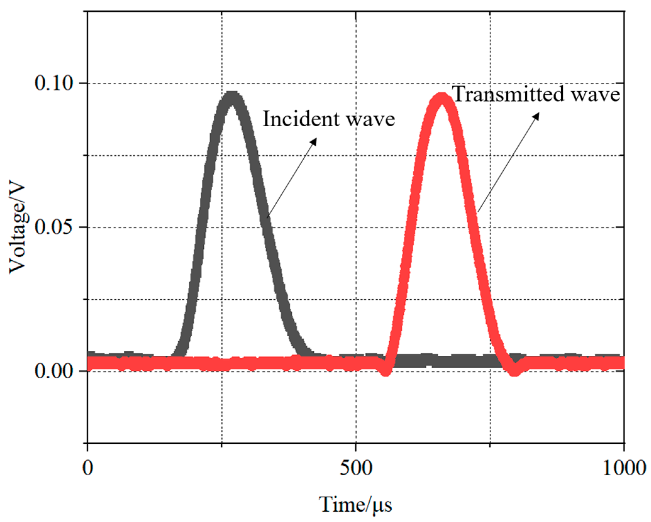
During the test, a no-specimen test was performed by directly placing the incident rod and transmission rod together. According to elastic wave theory, the incident bar pulse generated by the impact should be completely transmitted to the transmitted bar without producing any reflection. If the SHPB waveform shown in Figure 4 is obtained, it indicates that the test device is working properly, which can reduce the experimental errors caused by changes in the reflected wave shape.
After the test, the collected data were analyzed and processed, and the “three-wave method” was used to solve for the strain ε s t , strain rate ε ˙ s ( t ) , and stress of the specimen σ s t , as follows:
ε s ( t ) = C e L 0 t [ ε I ( t ) ε R ( t ) ε T ( t ) ] d t
ε ˙ s ( t ) = C e L [ ε I ( t ) ε R ( t ) ε T ( t ) ]
σ s ( t ) = E e A e 2 A s [ ε I ( t ) + ε R ( t ) + ε T ( t ) ]
In the equations, C e is the propagation velocity of the stress wave in the bar. L is the specimen thickness. t is the propagation time of the stress wave in the bar. E e is the elasticity modulus of the bar. A e is the cross-sectional area of the bar. A s is the end area of the specimen. ε I ( t ) is the incident wave. ε R ( t ) is the reflected wave. ε T ( t ) is the transmitted wave.
Since it is very difficult to apply a constant strain rate in an SHPB test, this paper uses the average strain rate of the entire test process for data analysis.

3.2. Amendatory Weibull Statistic Model

The Weibull model is a probability distribution model widely used in reliability engineering, survival analysis, and venture analysis. Since concrete is a non-homogeneous material, its strength and failure behavior exhibit significant randomness, and the Weibull model can well describe this randomness and its failure probability distribution.
The traditional three-parameter Weibull probability distribution model can be expressed as:
P = 1 e x p σ σ u σ 0 m ( σ σ u )
In the equation, P refers to the failure probability of the specimen. σ refers to the specimen strength. σ u refers to the location parameter. σ 0 refers to the scale parameter. m refers to the shape parameter.
From a safety perspective, if considered conservatively, the location parameter σ u can be ignored. In this case, the above three-parameter Weibull model is converted into a two-parameter Weibull model:
P = 1 e x p σ σ 0 m ( σ σ u )
In this study, an amendatory Weibull statistic model is proposed by considering the influence of strain rate, which is expressed as:
P = 1 e x p ε ˙ γ σ σ 0 m
In the equation, ε ˙ refers to the strain rate. γ refers to the strain rate effect parameter.
The three parameters ( γ , m , σ 0 ) of the above model can all be derived via the linear regression method [58]. Since the true failure probability P i of the specimens in this study is unknown, when calculating their failure probabilities, the test strengths of the specimens can first be sorted in ascending order, and the failure probability P i of each specimen can be estimated using Equation (7):
P i = i 1 + n
In the equation, P i refers to the failure probability of the i specimen. n refers to the total number of specimens.
Taking the natural logarithm of both sides of Equation (6) yields
ln [ ln ( 1 P ) ] = γ ln ε ˙ + m ln σ m ln σ 0
Through linear regression analysis, the shape parameter γ and m can be directly derived from the slope, and the scale parameter σ 0 can be derived from the intercept. Once the coefficients are obtained (i.e., the distribution is known), the average value σ ¯ of concrete compressive strength can be estimated using the moment method mentioned in Reference [59].
The average value σ ¯ can be calculated using Equation (9)
σ ¯ = σ 0 ( ε ˙ ) γ m Γ 1 + 1 m σ u
In the equation, Γ refers to the Gamma function. Since a two-parameter Weibull model is adopted in this study, the location parameter σ u is 0, and thus Equation (9) is transformed into the following equation (Equation (10)):
σ ¯ = σ 0 ( ε ˙ ) γ m Γ 1 + 1 m
The parameters are estimated using the following equations:
s 2 ( σ ¯ σ 1 ) 2 = Γ ( 1 + 2 m ) Γ 2 ( 1 + 1 m ) [ ( 1 n 1 m ) Γ 2 ( 1 + 1 m ) ] 2
s = σ 0 ( ε ˙ ) γ m Γ 1 + 2 m Γ 2 1 + 1 m
In the equation, s is the sample standard deviation of each group. σ 1 is the intensity of the first sample in each group of samples, arranged in ascending order.
According to the following equation, the average value σ ¯ 1 at a known strain rate ε ˙ 1 can be derived from the average value σ ¯ 2 at a known strain rate ε ˙ 2 by Equation (13):
σ ¯ 2 σ ¯ 1 = ε ˙ 2 ε ˙ 1 γ m

3.3. Fractal Theory

The fractal theory, proposed by scholar Mandelbrot, can be applied to study the characteristics of irregular shapes and curves that exhibit statistical self-similarity. The essence of impact damage to concrete lies in the process where the continuous initiation and propagation of microcracks—generated as concrete resists impact energy—ultimately lead to macroscopic damage and failure of the concrete. Studies have shown that the damage degree of concrete can be evaluated by analyzing the fractal dimension of the cracks formed in concrete during the impact process. There are generally two methods for calculating the fractal dimension: the first is the sieving method [60], which is used to determine the particle size distribution of granular materials; the second is the box counting method [61], which involves covering the fractal object with grids of different sizes and calculating the number of grids required for coverage to estimate the fractal dimension.
In this study, the box counting method was used to calculate the fractal dimension of dynamic impact damage in each specimen. A square grid of side length δ was used to cover the crack pattern. The number of boxes N ( δ ) that intersect the crack pattern is recorded. The relationship between box count and box size follows a power law:
N δ = a δ D
In the equations, a denotes the coefficient parameter; D denotes the fractal dimension.
Taking the logarithm of both sides of Equation (14) yields Equation (15):
log N = log a + D log δ
It can be seen from Equation (15) that log N is proportional to log δ , and the slope of the fitting curve between log N and log δ —which is the fractal dimension D —can be obtained through regression analysis.

3.4. Dynamic Increase Factor (DIF)

Concrete exhibits strain-rate sensitivity, and many studies have confirmed that the peak stress of concrete increases with strain rate. The Dynamic Increase Factor (DIF) for the dynamic compressive strength of concrete is a crucial indicator reflecting the variation law of strength with strain rate, and it can be calculated using Equation (16).
D I F = f c d f cs
In the equation, f c d denotes the dynamic compressive strength; f cs denotes the static compressive strength.

4. Experimental Results and Analysis

4.1. Failure Modes Under Dynamic Impact Loading

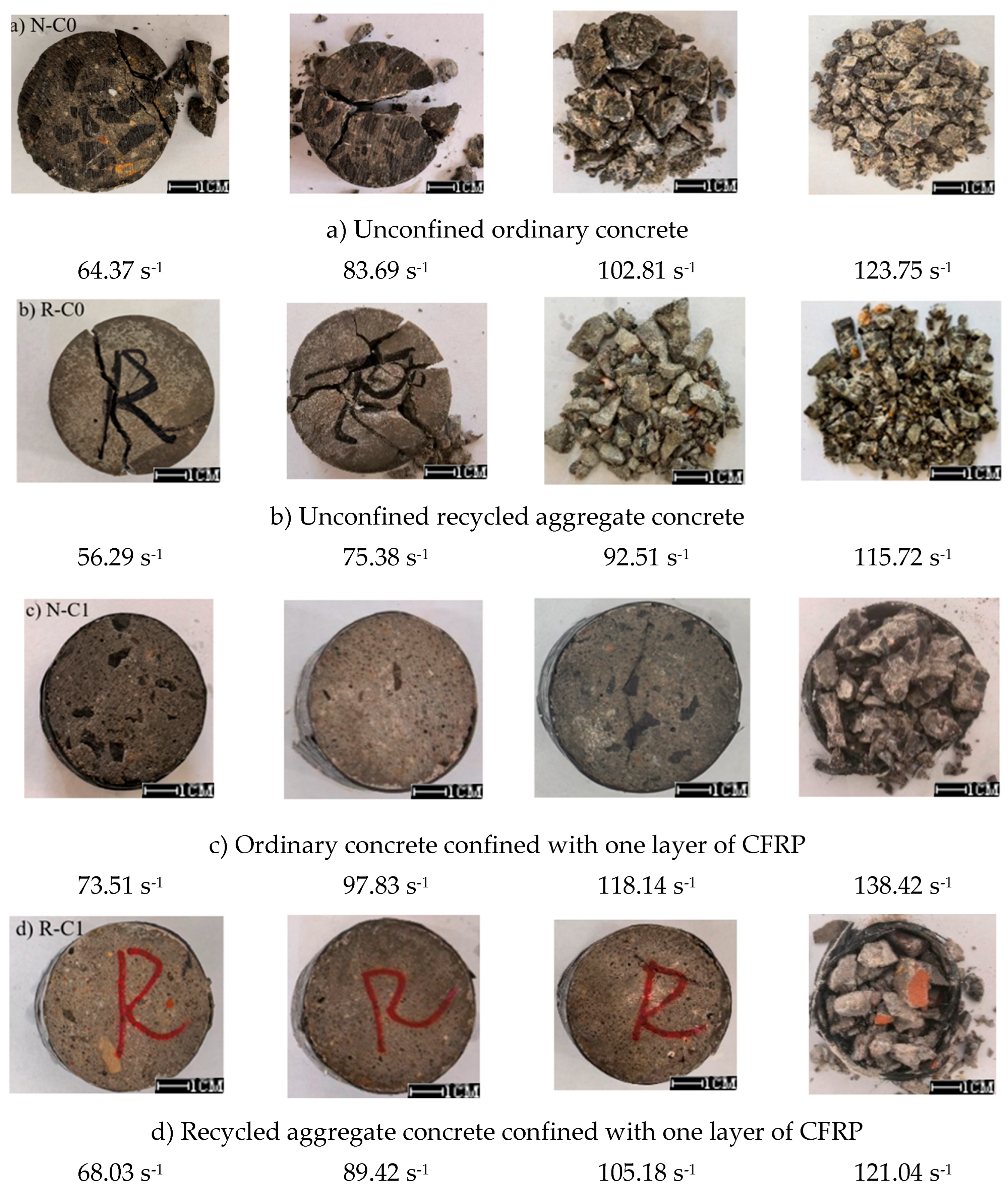
The typical failure modes of specimens under impact loading are shown in Figure 5. It can be seen from the figure that with the increase of strain rate, both unconfined ordinary concrete and recycled concrete exhibit a process from fracture, fragmentation to pulverization. This indicates that concrete is a strain-rate-sensitive material, and the higher the strain rate, the poorer the integrity of the specimens. Within the same range of strain rates, the integrity of recycled concrete specimens is worse than that of ordinary concrete specimens. However, compared with unconfined specimens, with the increase of strain rate, both CFRP-confined ordinary concrete and CFRP-confined recycled specimens exhibit a similar failure process; that is, the specimens gradually develop from a state with no obvious surface cracks to CFRP cracking and finally to CFRP being pulled apart.
Table 5 presents the detailed damage status of the specimens. As can be seen from the table, for Specimen R-C0 and Specimen N-C0, with the increase in average strain rate, their failure mode gradually evolves from large-block cracking to crushing. This is because at a lower strain rate, the internal cracks of the material have sufficient time to propagate and connect, resulting in large-block failure. In contrast, at a high strain rate, energy is input rapidly, and crack propagation is fast, leading to more severe crushing failure of the material. For Specimen R-C1 and Specimen N-C1, there were no obvious cracks on the surface under certain strain rates (e.g., 73.48 s−1 and 61.09 s−1). This is due to the confinement effect of the carbon fiber sheet, which restricts the initial propagation of cracks. As the strain rate increased, surface cracks appeared, and in some cases, even concrete fragmentation and CFRP (carbon fiber reinforced polymer) breakage occurred. During the load-bearing process of the carbon fiber sheet, it first shares part of the stress through its own tensile performance, delaying the cracking of the concrete. Only when the strain rate further increases and the load exceeds the bearing capacity of the carbon fiber sheet will more severe damage occur.

4.2. Dynamic Stress–Strain Curves

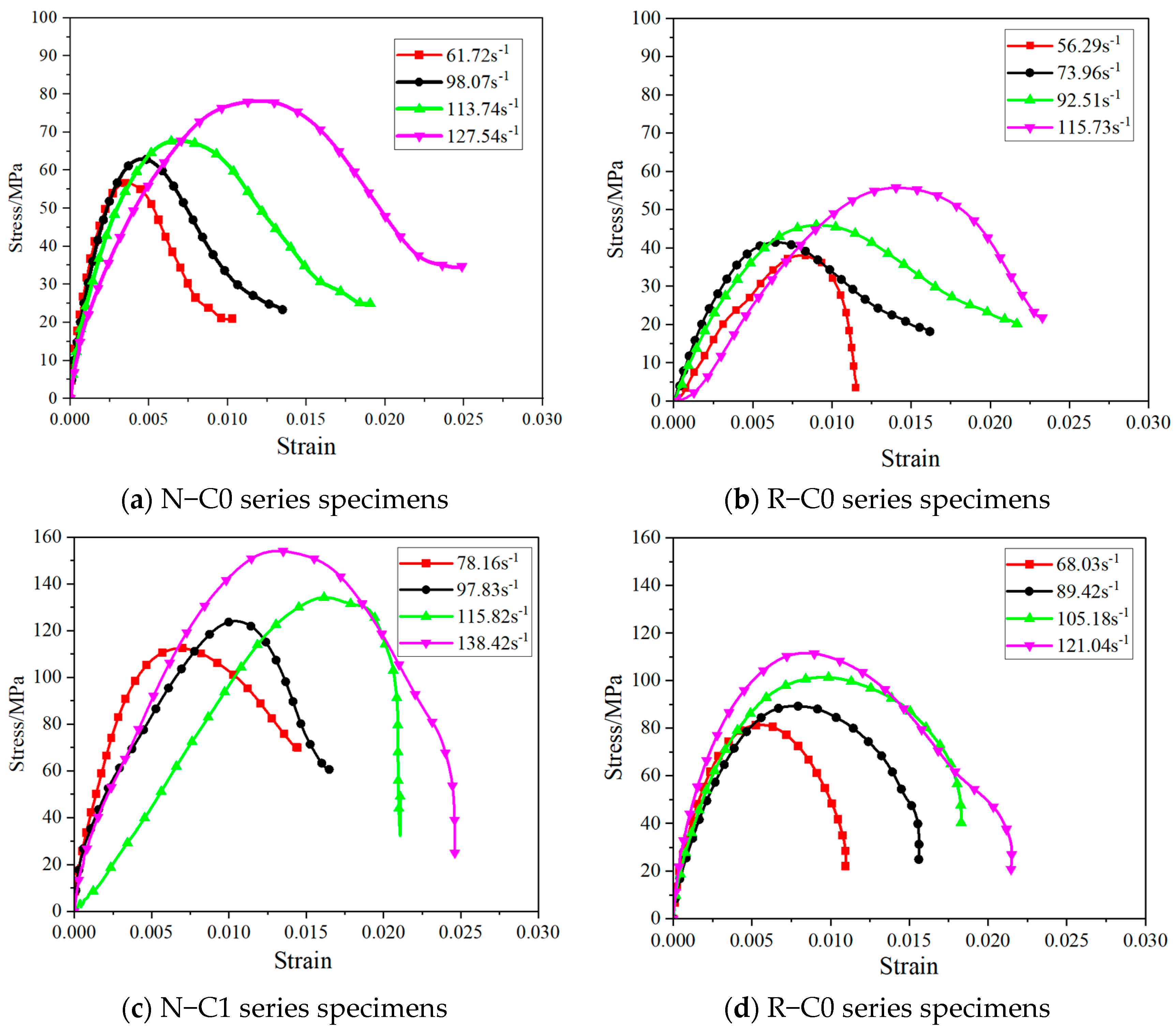
Based on Equations (1)–(3), the dynamic compressive stress and strain of each specimen can be calculated. The stress–strain curves are plotted in Figure 6. As shown in the figure, the stress–strain curves of the specimens exhibit a similar pattern, which can be divided into three stages: the elastic stage, the elastoplastic deformation stage, and the failure stage. In the elastic stage, the N-C0 series specimens have the longest linear segment. This is because the interfacial transition zone between the natural aggregate and the cement paste (used in N-C0 series) has a dense structure with few defects, enabling uniform stress transmission inside the material. Local damage is less likely to occur in the early stage, thus ensuring greater stability of the internal structure during the initial phase. In contrast, the R-C0 series specimens have the shortest linear segment, and their elasticity modulus fluctuates significantly with the strain rate. This is due to the residual old mortar layer and microfracture that may exist on the surface of recycled aggregates, resulting in a large number of randomly distributed defects in the interfacial transition zone. Under dynamic loading, these defects tend to cause stress concentration, leading the material to deviate from the linear relation at relatively low strains. Meanwhile, the uneven distribution of defects also causes large fluctuations in stiffness, making it difficult for the elasticity modulus to remain stable as the strain rate changes. When entering the plastic stage, the linear relation between stress and strain is broken, and the curve begins to show nonlinear bending. This indicates the onset of plastic deformation and the propagation of microcracks inside the material.
Compared with CFRP-confined specimens, the elastoplastic stages of unconfined specimens N-C0 and R-C0 are relatively short, and they become obviously visible mostly when the stress is close to the peak value. Due to more interface defects in recycled aggregates, the starting point of nonlinearity of R-C0 is slightly lower than that of N-C0, meaning it enters the elastoplastic state earlier. Additionally, the curve of R-C0 shows a greater degree of bending, which indicates that the plastic deformation develops faster. With the increase of strain rate, the strain range of the elastoplastic stage for both specimens shrinks. At high strain rates, the specimens become more brittle, transitioning rapidly from the elastic stage to the peak stress, leaving no sufficient time for the full development of plastic deformation. In contrast, the elastoplastic stages of confined specimens N-C1 and R-C1 are significantly longer, with a wider strain variation range from the end of the elastic stage to before the peak stress. This is because the hoops confinement of CFRP continuously resists the lateral expansion of the specimens, delays the penetration of microcracks, and allows the gradual accumulation of plastic deformation. Furthermore, the length of the elastoplastic stage of CFRP-confined specimen R-C1 is relatively close to that of specimen N-C1. Although it shortens slightly as the strain rate increases, it generally reflects the role of CFRP confinement in improving the deformation capacity of the specimens. Moreover, this improvement effect is more prominent in recycled concrete.

4.3. Energy Dissipation and Impact Toughness Analysis

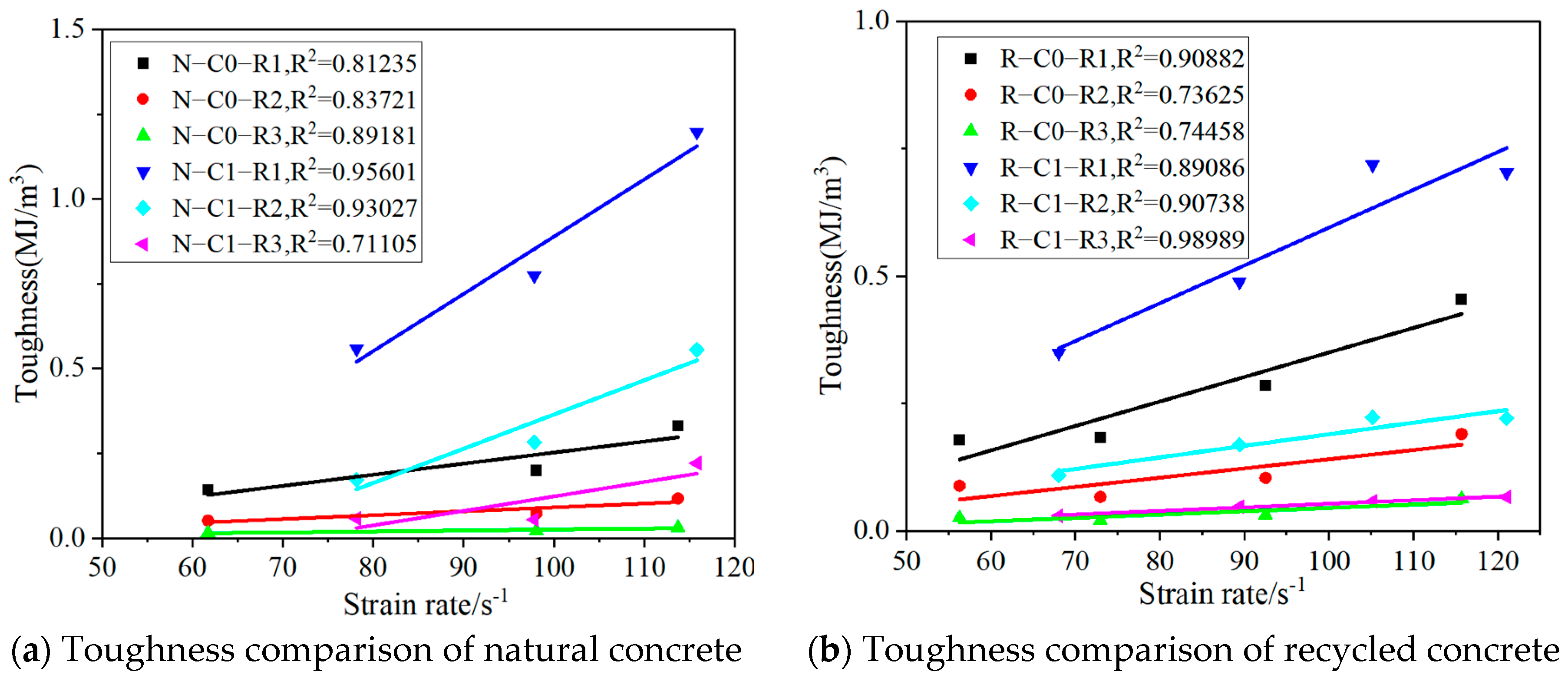
Energy dissipation capacity is a key indicator for evaluating the impact resistance of materials, and impact toughness can be defined as the ability of a material or structure to absorb energy from loading to failure. Recycled aggregate concrete (RAC) exhibits higher energy absorption efficiency than ordinary concrete under confinement, because its porous structure and complex crack paths at the old–new mortar interfaces facilitate energy dispersion and dissipation, thereby reducing strain-rate sensitivity. To systematically investigate the toughening effect of CFRP on recycled aggregate concrete, this study uses the area enclosed by the stress–strain curve to quantify and characterize toughness. Figure 7 presents the toughness indices at three key stress levels: toughness at peak stress, (R1); toughness at 0.8 times the peak stress, (R2); and toughness at 0.5 times the peak stress, (R3). It can be clearly observed that the (R1), (R2), and (R3) values of CFRP-confined recycled aggregate concrete are all higher than those of the corresponding unconfined recycled aggregate concrete. This result directly confirms the significant toughening effect of CFRP on recycled aggregate concrete. In addition, most of the fitted curves in the figure show good linear relationships, indicating that the toughness of recycled aggregate concrete increases linearly with increasing strain rate. Furthermore, the slopes of the fitted curves for CFRP-confined recycled aggregate concrete are greater than those for unconfined recycled aggregate concrete, meaning that the toughness of CFRP-confined recycled aggregate concrete increases more rapidly with increasing strain rate. This further highlights the enhancement effect of CFRP on energy absorption under dynamic loads.

4.4. Dynamic Compressive Strength vs. Strain Rate

Table 5 presents the dynamic compressive strength of various specimen series. As indicated in the table, under similar average strain rates, for the R-C0 series specimens, when the average strain rate increased from 60.07 s−1 to 119.47 s−1, the dynamic compressive strength rose from 37.45 MPa to 52.63 MPa, representing an increase of 40.5%. For the N-C0 series specimens, as the average strain rate increased from 68.71 s−1 to 129.31 s−1, the dynamic compressive strength increased from 53.45 MPa to 76.55 MPa, showing a growth of 43.2%. This demonstrates that an increase in strain rate significantly enhances the dynamic compressive performance of the material. Moreover, this enhancement effect exhibits a relatively consistent trend across different specimen series, further verifying the strain rate strengthening characteristics of the specimens under dynamic loads. Under similar average strain rates, a comparison between the R-C0 and R-C1 series specimens reveals that when the average strain rate is approximately 100 s−1, the dynamic compressive strength of the R-C0 series is 41.75 MPa, while that of the R-C1 series reaches 87.54 MPa—with the latter being 2.10 times that of the former. For the N-C0 and N-C1 series specimens, when the average strain rate is approximately 68.71 s−1, the dynamic compressive strength of the N-C0 series is 53.45 MPa, and that of the N-C1 series is 110.54 MPa—where the latter is 2.07 times that of the former. This is because CFRP, owing to its excellent mechanical properties, can profoundly intervene at the microscopic scale in the entire process of crack initiation and propagation inside concrete, effectively suppressing crack branching and ultimately reducing the fractal dimension of the overall crack system. Under impact axial compression, concrete undergoes significant lateral expansion due to the Poisson effect. In the absence of external confinement, the tensile stress generated by lateral expansion can be freely released, further aggravating microcrack initiation and lateral propagation in the interfacial transition zones and providing sufficient stress conditions for multi-directional crack branching. CFRP has extremely high tensile strength and elastic modulus. When slight lateral expansion deformation occurs in concrete, the externally wrapped CFRP sheet can rapidly generate a stable passive hoop confinement force, effectively offsetting the lateral tensile stress generated inside the concrete, substantially weakening stress concentration at defect locations and interface regions, and limiting the opening degree and lateral extension range of existing microcracks. This greatly reduces the basic conditions required for crack branching. The SHPB impact test is a short-duration, high-energy dynamic loading process, in which severe stress wave oscillations can easily induce repeated opening and closing disturbances of internal cracks in concrete, further generating numerous disordered secondary cracks and intensifying crack branching. CFRP fiber bundles can dissipate impact input energy through various microscopic deformation mechanisms, including fiber tensile deformation, microslip between fibers and the bonding matrix, and slight interfacial debonding. This allows CFRP to share the dynamic impact load borne by the concrete matrix, weaken the reflection and superposition disturbance effects of stress waves inside concrete, and reduce the intensifying effect of dynamic stress fluctuations on microcrack development. Meanwhile, the external confinement can compact the loose pores inside concrete, improve the uniformity of the internal mesoscopic structure, reduce weak points prone to stress concentration, and further decrease crack-branching nucleation sites, making it difficult for concrete to form a complex and interlaced multilevel crack network during impact failure. This once again confirms that the confinement provided by CFRP (carbon fiber reinforced polymer) sheets is conducive to improving the impact resistance of the specimens.
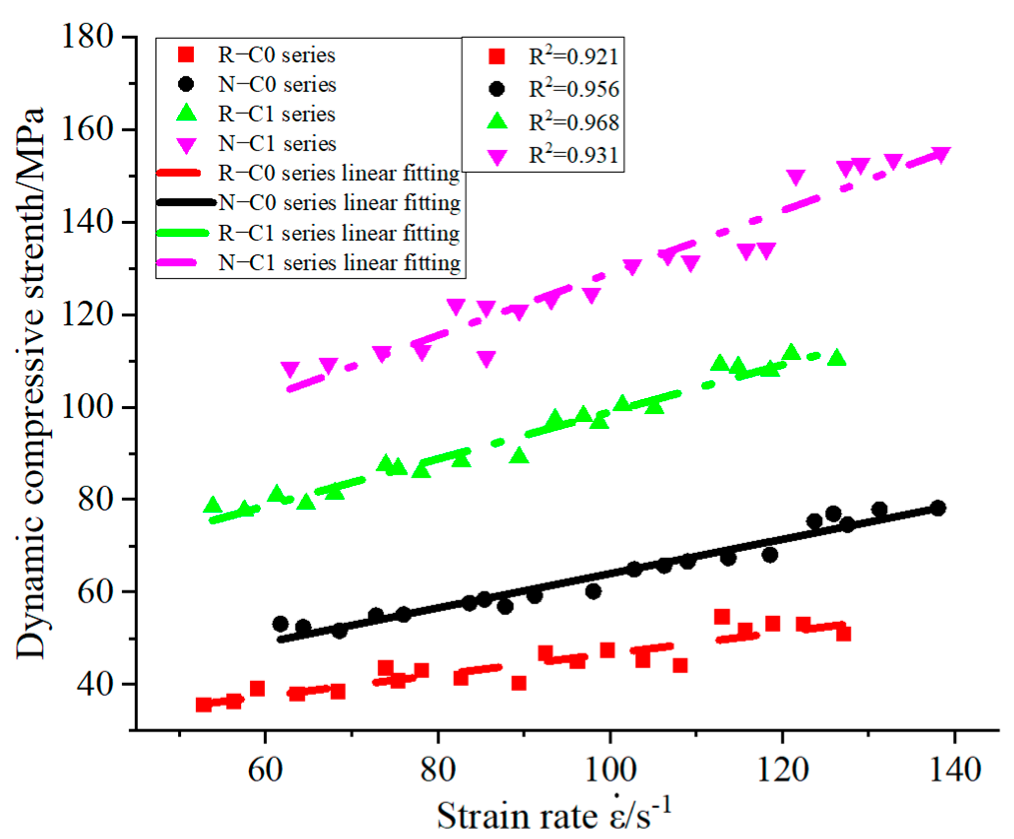
Figure 8 plots the relationship between dynamic compressive strength and strain rate for different specimens. The results show that dynamic compressive strength exhibits a linear strain rate effect, with the slopes of the linear fitting results for the R-C0, N-C0, R-C1, and N-C1 series specimens being 0.231, 0.372, 0.509, and 0.673, respectively, indicating a sequentially increasing tendency of the strain rate effect. The strain rate effect of the R-C0 series specimens is relatively weak, which is related to the characteristics of the interfacial transition zone caused by the internal recycled aggregate; its dynamic compressive strength increases more gradually with strain rate changes. The strain rate effect of the N-C0 series specimens is more pronounced than that of the R-C0 series because the natural aggregate has more stable properties and a denser interfacial bond, resulting in a more significant increase in dynamic compressive strength under the same strain rate variation. For the R-C1 series specimens, the strain rate effect is further enhanced by the constraint of CFRP. The hoops confinement of CFRP effectively limits the lateral deformation of the concrete, making the increase in dynamic compressive strength more sensitive to strain rate changes. Compared with the N-C1 series, the performance degradation of the R-C1 series is caused by the systematic amplification of the inherent “multiple interfacial defects” in recycled aggregate concrete under the coupled action of high-strain-rate impact and CFRP confinement. Specifically, the microstructure of recycled aggregate concrete contains obvious inherent defects, mainly reflected in its complex interfacial transition zones (ITZs) and high porosity. A layer of old hardened cement mortar inevitably adheres to the surface of recycled aggregates, causing recycled aggregate concrete to contain an “old ITZ” between the original aggregate and old mortar, a “new ITZ” between the old mortar and the new matrix, and an interface transition zone between the new and old mortars during loading. This forms a multiple-ITZ system that is more complex than that of ordinary concrete. These multiple interfacial transition zones are mechanically much weaker than the surrounding matrix and have significantly higher porosity, representing the microscopic root cause of the deterioration of the mechanical properties of recycled aggregate concrete. When high-strain-rate impact loading is applied to CFRP-confined specimens, the effect of these inherent microdefects is significantly amplified. Under high-strain-rate impact conditions, cracks first initiate at microscopic weak locations such as interfacial transition zones and then rapidly propagate along these weak interfaces, forming connected damage networks. It should be noted that this damage evolution process is highly time-coupled. Because recycled aggregate concrete contains high-porosity regions and multiple ITZs throughout its internal structure, local stress concentrations generated during stress wave propagation can simultaneously trigger microcrack initiation at multiple weak locations. These cracks are more likely to connect with each other during propagation and form macroscopic damage zones. The rate of this process is significantly higher than that in relatively homogeneous ordinary concrete.
The N-C1 series specimens exhibit the strongest strain rate effect among the four types. The excellent matrix performance of ordinary concrete combined with the efficient confining effect of CFRP ensures that even minor variations in strain rate lead to a significant linear increase in dynamic compressive strength.

4.5. Dynamic Strength Analysis Based on Modified Weibull Statistical Model

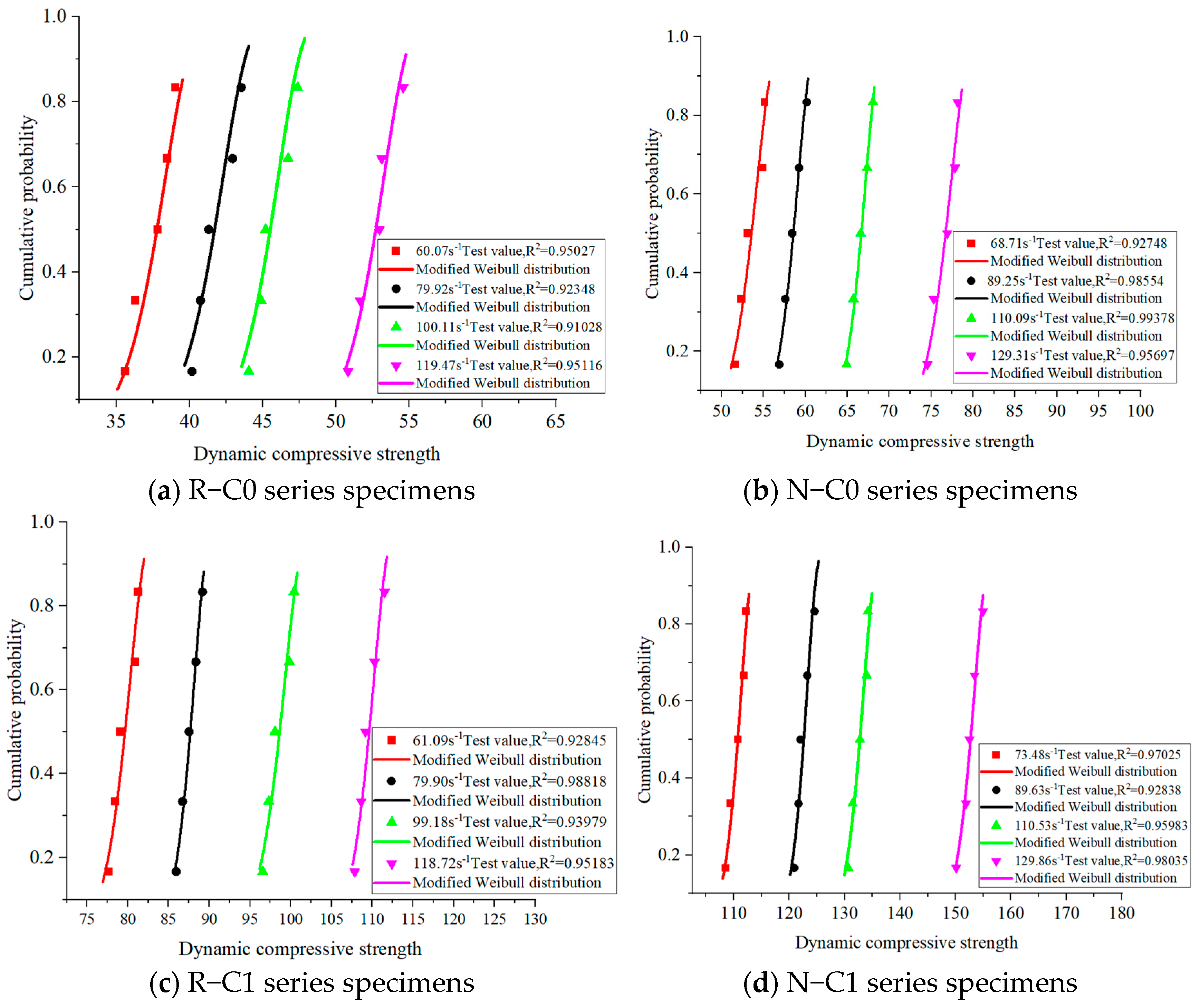
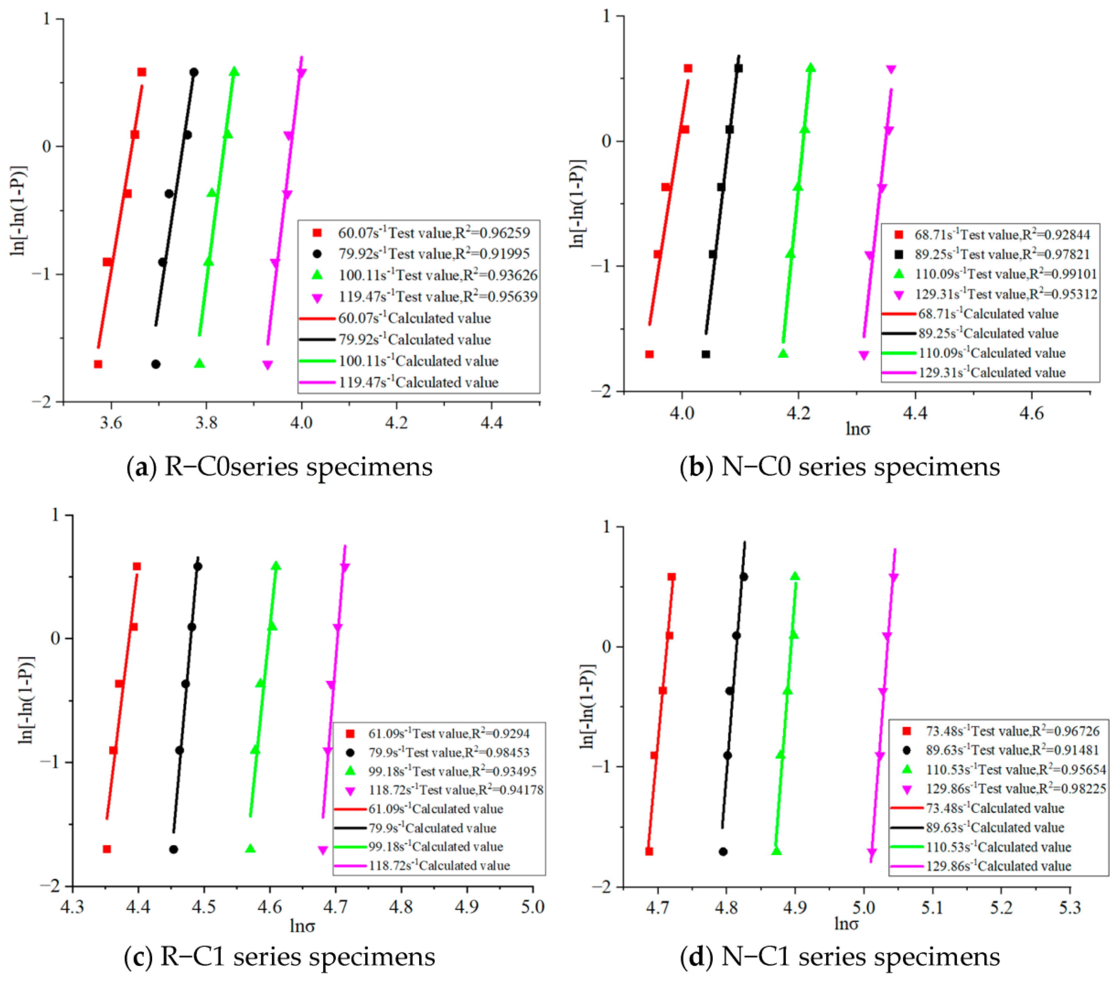
The Weibull parameters computed based on Section 3.2 are listed in Table 6, and fitting curves under various strain rates are shown in Figure 9. The results exhibit a strong linear correlation, indicating high consistency between the experimental values and theoretical values. The parameters m, γ, and the scale parameter, obtained from the intercept and slope of the fitting lines, are also presented in Table 6. Furthermore, the Kolmogorov–Smirnov goodness-of-test (K-S) was performed at a confidence level of 0.05, and the results are given in Table 6. When Dn < Dnc, the compressive strength data conform to the modified Weibull statistical model. The cumulative probability distribution curves of dynamic compressive strength for each specimen are shown in Figure 10, confirming that the proposed model accurately describes the probability distribution of dynamic compressive strength.
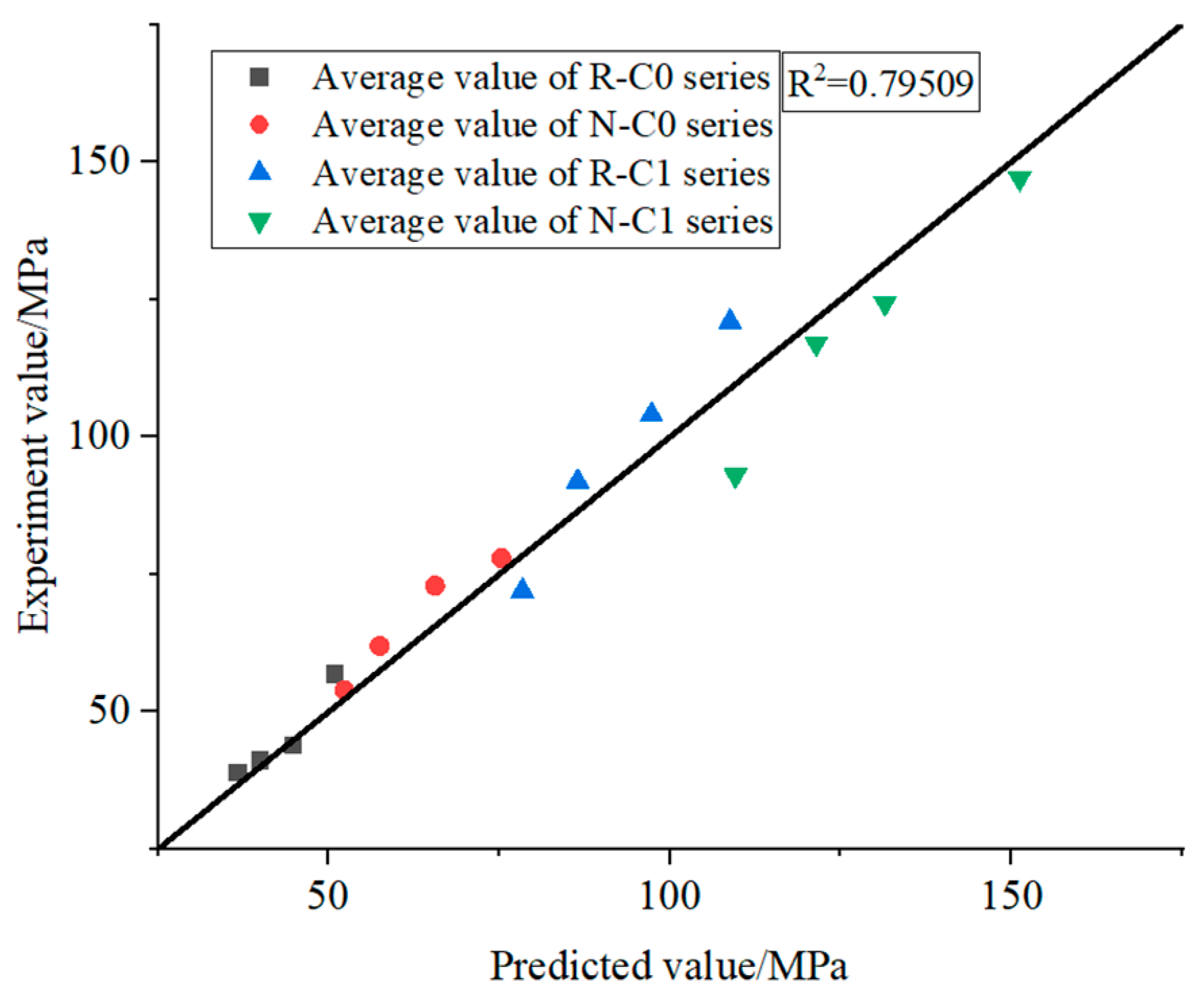
The comparison between the predicted values obtained from the modified Weibull model and the experimental values measured from the SHPB test is shown in Figure 11. The results demonstrate that the modified Weibull statistical model has good applicability for predicting the dynamic compressive strength of specimens.

4.6. Analysis of DIF–Strain Rate Relationship

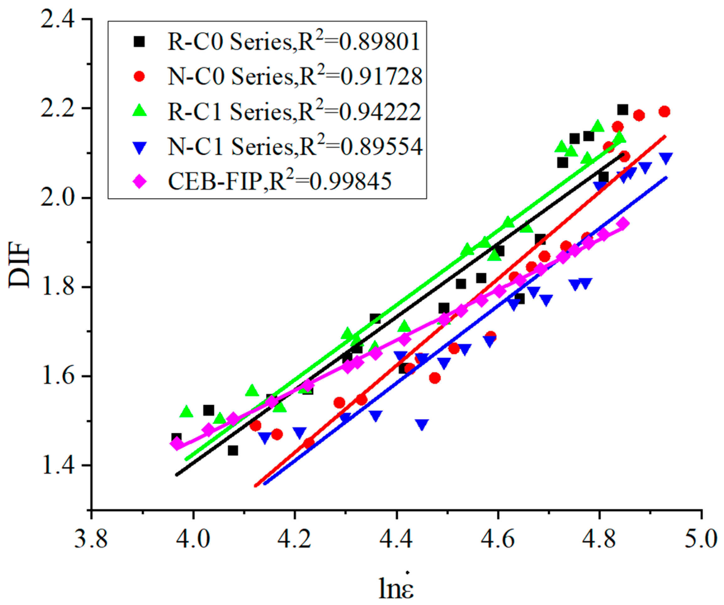
Figure 12 illustrates the relationship between the DIF and strain rate. All specimens exhibit a linear correlation, with DIF increasing as strain rate rises. Table 5 lists the average strain rate and corresponding DIF values. The N-C0 series shows the highest sensitivity; when strain rate increases from 68.71 s−1 to 129.31 s−1, DIF rises from 1.50 to 2.19, corresponding to a 0.52% increase in DIF per 1% increase in strain rate. This behavior is attributed to the internal three-phase structure (cement paste, aggregate, and ITZ), where the aggregate–matrix synergy at high strain rates suppresses ITZ damage and accelerates DIF growth. In contrast, the N-C1 series shows a much milder increase. A 94.3% rise in strain rate leads to only a 38.3% increase in DIF, with sensitivity reduced to 0.41%. This is because CFRP confinement has already enhanced the static strength, narrowing the margin for further dynamic compressive strength gain, while its linear elasticity restricts the growth at high strain rates. The R-C0 series reaches a peak DIF of 2.20, slightly higher than N-C0’s 2.19, though its sensitivity (0.46%) is lower. This is due to the multi-interface structure formed by old mortar on the surface of recycled aggregates; at low strain rates, the interface acts as a weak zone, but at high strain rates, it promotes energy dissipation and delays crack propagation, releasing the potential for dynamic compressive strength enhancement. The R-C1 series shows stage-dependent behavior. In the strain rate range of 73.48–110.53 s−1, its DIF exceeds that of R-C0, reflecting CFRP’s compensating effect on multi-interface defects. However, when the strain rate exceeds 110.53 s−1, the DIF of R-C1 (2.08) drops below R-C0 (2.20) because brittle fracture of CFRP causes confinement failure, while the intrinsic multi-interface energy dissipation of recycled concrete continues to play a role.
The CEB-FIP model is an empirical model for estimating the dynamic increase factor (DIF) of ordinary concrete, and its expression is as follows:
DIF = ε ˙ / ε ˙ 0 0.014 for   ε ˙ 30   s 1 0.012 ε ˙ / ε ˙ 0 1 3 for   ε ˙ > 30   s 1
where ε ˙ 0 = 30 × 10 6   s 1 . Here, the DIF variation curve defined by the CEB-FIP model is also plotted in Figure 12. The results show that this model is not applicable to the experimental data of all the investigated series. Within the strain rate range of this study, the DIF values predicted by the CEB-FIP model are generally lower than the measured values of each experimental series. The linear fitting curves of the experimental data for the R-C0, N-C0, R-C1, and N-C1 series intersect with the CEB-FIP model curve at strain rates of approximately 64 s−1, 95 s−1, 62 s−1, and 116 s−1, respectively. It is worth noting that before these four transition strain rates, the DIF values predicted by the CEB-FIP model are higher than the experimental values; after the transition strain rates, however, the increase in DIF predicted by the model with increasing strain rate is slower than that observed experimentally.
The DIF obtained can be used to modify the design value of the axial compressive strength of concrete. Under dynamic loads such as explosions, impacts, and vehicle collisions, the dynamic compressive strength of concrete can be expressed as the standard static strength multiplied by the DIF, allowing the bearing capacity verification of member sections to shift from a static assumption to a dynamic assessment that considers strain rate effects. In addition, DIF data are key input parameters for establishing dynamic constitutive models and finite element numerical simulations. In software such as LS-DYNA V971 R6 and ABAQUS 2026, the experimentally obtained DIF–strain rate relationship can be embedded into concrete dynamic constitutive models such as HJC and RHT. By calibrating the rate-effect parameters, numerical simulations can more accurately predict the stress distribution, crack propagation, and failure mode of members under impact loads, thereby supporting the refined design and optimization of structural impact resistance.

4.7. Fractal Dimension Analysis

4.7.1. Analysis of Relationship Between Fractal Dimension, Dynamic Compressive Strength, and Strain Rate

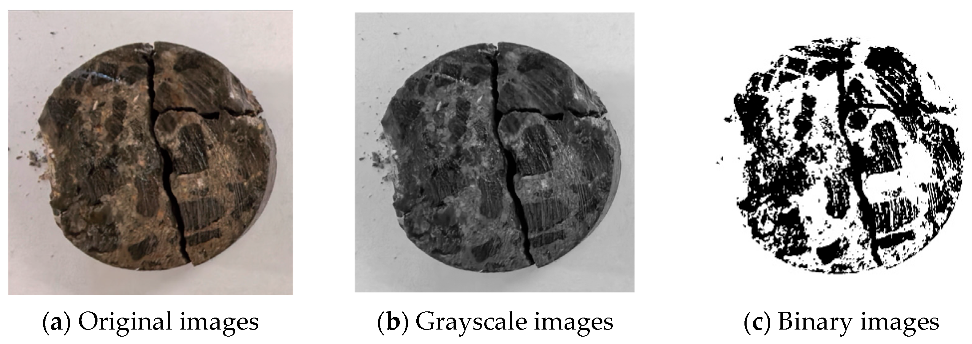
The surface crack patterns of the specimens were processed into 1024 × 1024-pixel grayscale images, as shown in Figure 13. Then, the two-dimensional fractal dimension, D, of each specimen was calculated using Equation (15) and MATLAB R2026a.
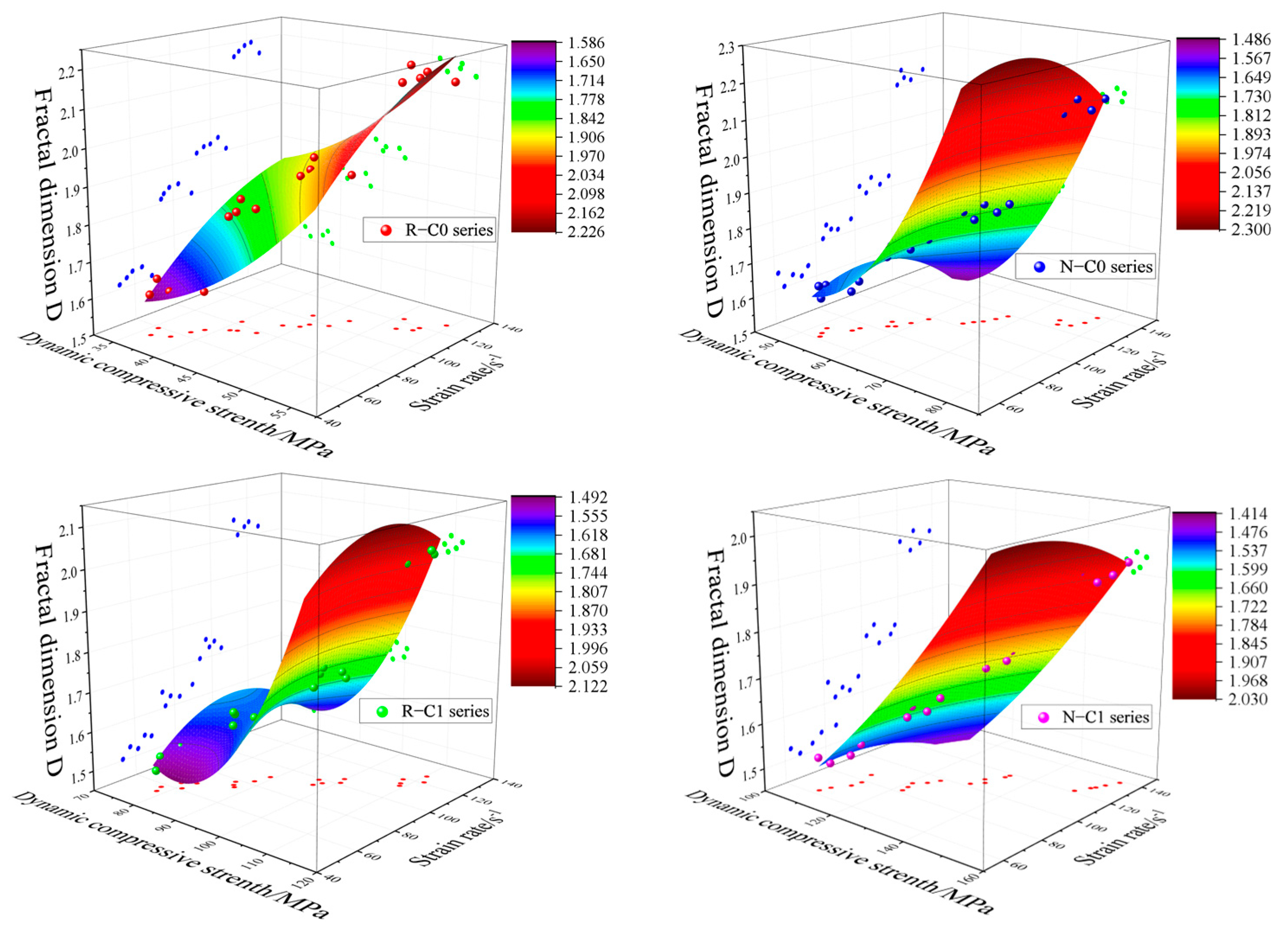
Figure 14 illustrates the scatter plots of fractal dimension versus strain rate and dynamic compressive strength. It can be observed that at lower strain rates, the values of D are relatively small, while they gradually increase with the rise of strain rate. This indicates that increasing strain rate leads to changes in the fractal characteristics of the material, which can be attributed to internal damage or structural evolution. At the same time, dynamic compressive strength also varies with strain rate, further confirming that strain rate is a key factor influencing both the mechanical properties and fractal features of the material. Under impact loading at different strain rates, the specimens undergo energy absorption and dissipation. At lower strain rates, internal damage develops slowly, and the lower D values suggest a simpler damage pattern. As strain rate increases, the rapid loading accelerates microcrack propagation and interaction, resulting in a more complex damage structure and higher fractal dimension. Such complex internal damage leads to stress concentration and energy dissipation, thereby reducing the dynamic compressive strength. In summary, increasing strain rate and dynamic compressive strength amplifies the degree of fragmentation observed in the SHPB tests.
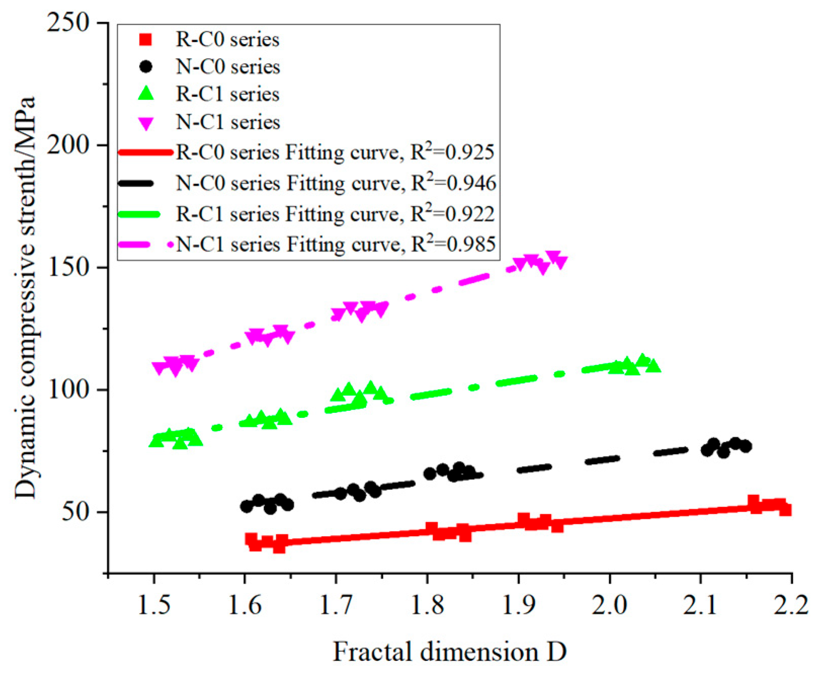
Figure 15 shows the relationship between fractal dimension and dynamic compressive strength of the specimens. A positive correlation is observed across all specimen series. For the R-C0 series, within the D range of 1.6–1.8, each 0.1 increase in D corresponds to an average increase in dynamic compressive strength of approximately 2.26 MPa (e.g., from 39.03 MPa at D = 1.607 to 43.54 MPa at D = 1.805). In the D range of 1.8–2.2, the increment rises to 3.16 MPa per 0.1 increase (e.g., from 43.54 MPa at D = 1.805 to 54.59 MPa at D = 2.158), representing an approximate 40% enhancement. Beyond a certain threshold of D, the increase in dynamic compressive strength becomes more pronounced. The N-C0 series exhibits a similar trend. In the D range of 1.6–1.8, each 0.1 increase in D corresponds to an increase of about 6.68 MPa, while in the 1.8–2.1 range, this increment decreases to 3.19 MPa, a reduction of approximately 52.2%. Nevertheless, the overall increment remains slightly higher than that of the R-C0 series. This difference reflects the inherent disparities in densification and interfacial bonding between normal aggregate and recycled aggregate. For instance, at D = 1.6, the dynamic compressive strength of the N-C0 series (52.37–55.14 MPa) is approximately 44.1% higher than that of the R-C0 series (35.61–39.03 MPa).
When the fractal dimension is 2.0, the strength of the N-C0 series specimens, ranging from 75.29 to 78.14 MPa, is approximately 67.8% higher than that of the R-C0 series specimens, which is between 44.05 and 47.38 MPa. This indicates that the difference in dynamic compressive strength between the specimens increases as the fractal dimension rises. The N-C1 and R-C1 series specimens, however, exhibit a distinctive pattern; their initial fractal dimensions (1.503–1.506) are about 6.2% lower than those of the unconstrained type (1.602–1.607). However, the strength increment per 0.1 increase in fractal dimension (5.6–9.8 MPa) is comparable to that of the unconstrained type. This suggests that CFRP confinement mainly reduces the fractal dimension by suppressing initial defects, but does not change the internal structural complexity or the intrinsic growth logic of dynamic compressive strength.
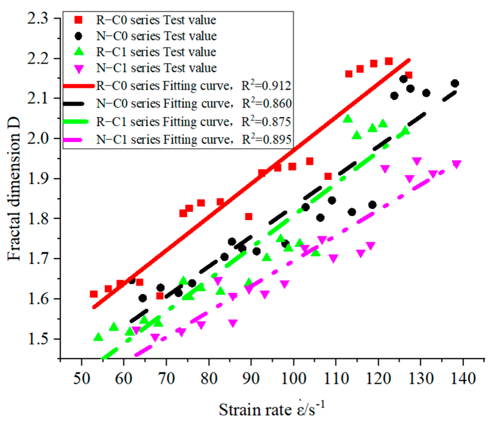
Figure 16 presents the relationship between fractal dimension and strain rate of the specimens. It can be seen from the figure that there is also a strong linear relationship between the fractal dimension and strain rate. When the strain rate of the R-C0 series specimens increases from 52.85 s−1 to 127.16 s−1, the fractal dimension increases from 1.612 to 2.158. When the strain rate reaches a higher range such as 113.05 s−1 and above, the fractal dimension exceeds 2.1, indicating a significant change in structural complexity. For the N-C0 series specimens, as the strain rate increases from 61.72 s−1 to 138.06 s−1, the fractal dimension increases from 1.647 to 2.138, with a slightly lower slope compared to the R-C0 series specimens. This indicates that specimens with fewer micro-pores inside are less likely to generate dispersed micro-cracks under rapid loading, which also suggests that the N-C0 series specimens have relatively fewer internal micro-pores and a lower possibility of generating dispersed micro-cracks under rapid loading. Compared with the R-C0 series specimens, the slope of the fractal dimension change with strain rate for the N-C0 series specimens is slightly gentler. For the R-C1 series specimens, as the strain rate increases from 53.86 s−1 to 126.32 s−1, the fractal dimension increases from 1.503 to 2.019, with a slope similar to that of the R-C0 series specimens. This indicates that the degree of change for the R-C1 series specimens is similar to that of the R-C0 series specimens.
When the strain rate of the N-C1 series specimens increased from 62.84 s−1 to 138.42 s−1, the fractal dimension increased from 1.524 to 1.938, and the slope was the smallest among all the series of specimens. This indicates that when CFRP is combined with ordinary concrete, it has a stronger inhibitory effect on the change in damage degree. The upper limit of the fractal dimension for the R-C0 series specimens and N-C0 series specimens was 2.193 and 2.149, respectively, which was higher than that of the constraint types (2.048 and 1.946). For example, at a strain rate of approximately 138 s−1, the fractal dimension of the N-C0 specimen reached 2.138, while that of the N-C1 series specimen only reached 1.938, with a difference of 0.2. This shows that through the lateral restriction of the specimen N-C0 by CFRP, the strain rate threshold required for the growth of the fractal dimension was increased, and the constrained concrete needed a higher loading rate to form the material internal structure characteristics similar to those of unconstrained concrete. By fitting the fractal dimension and strain rate line, the correlation coefficient R2 values of the fitting equation were all greater than 0.90 (see Table 7), indicating that the fitting equation has a good correlation with the experimental results, and also indicating that the fractal dimension can be used to directly evaluate the dynamic impact damage degree of the specimen.

4.7.2. The Relationship Between Fractal Dimension and DIF

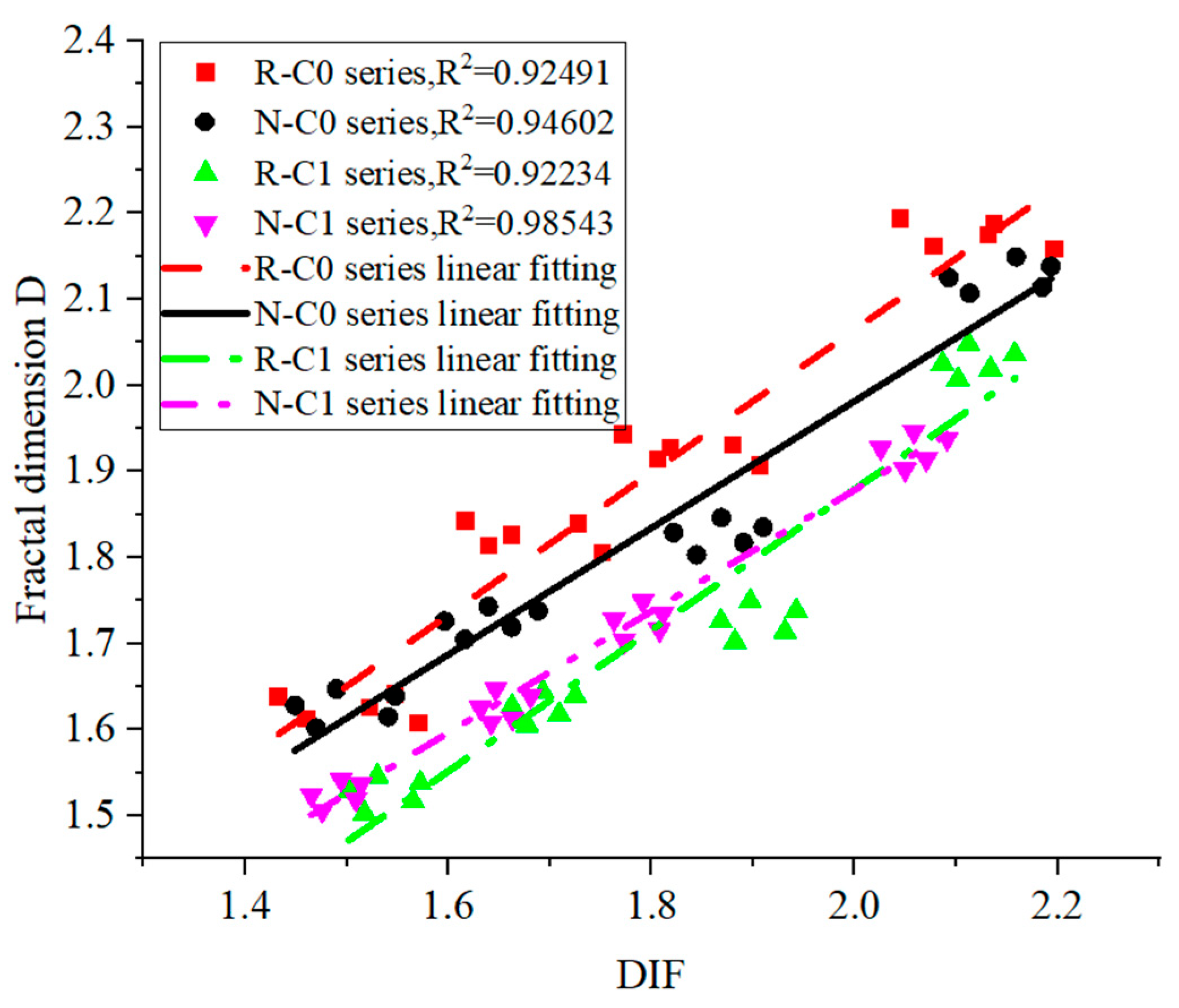
Figure 17 presents the relationship between fractal dimension and DIF of the specimens. From the figure, it can be seen that the DIF of each series of specimens shows a significant positive correlation with the fractal dimension. For example, in the R-C0 series of specimens, the DIF increased from around 1.46 to around 2.20, with an increase of approximately 51%, while the fractal dimension increased from around 1.61 to around 2.19, with an increase of approximately 36%. Other series of specimens also exhibited similar patterns. This indicates that during the dynamic loading process, the increase in the dynamic compressive strength of the specimens is mutually reinforcing with the improvement in the complexity of the internal structure of the specimens. When the impact rate is low, the internal structure changes of the material are relatively simple, the fractal dimension is lower, and the dynamic strength increases limitedly, with a smaller DIF. As the impact rate increases, micro-cracks begin to appear inside the specimen, the internal structure complexity increases, the fractal dimension increases, and the dynamic compressive strength also increases due to the strain rate effect, with the DIF increasing accordingly. Approaching the limit state, the internal structure of the specimen becomes highly complex, the fractal dimension reaches its peak, and the dynamic strength also reaches its maximum value, with the DIF being the highest.
When the DIF is within the range of 1.6–1.9, the peak DIF value of the R-C1 series specimens reaches 1.942, which is 3.3% higher than that of the R-C0 series specimens (1.880) and 2.7% higher than that of the N-C0 series specimens (1.890). However, the highest DIF value of the N-C1 series specimens is 1.811, significantly lower than that of the R-C1 series specimens. This is because there are more Interface Transition Zones within the recycled concrete, and under dynamic loads, stress concentration is prone to occur. The CFRP restraint can effectively limit the expansion of cracks in these areas, resulting in a more significant increase in dynamic performance. Ordinary concrete has a more uniform internal structure, and the stress concentration points for crack expansion are fewer. The performance improvement brought by the CFRP restraint is naturally lower. When the DIF is greater than 2.0, the opposite characteristics are presented; the maximum DIF value of the R-C0 series specimens is 2.197, and that of the N-C0 series specimens is 2.193, both of which are 1.8% higher than that of the R-C1 series specimens (2.158) and 4.9% higher than that of the N-C1 series specimens (2.091). Under high dynamic loads, the internal cracks of the unrestrained concrete expand rapidly and form a complex network. Through the dissipation of energy and structural reorganization, the bearing capacity is enhanced, while the CFRP’s strong restraint limits the full development of cracks, reducing the energy dissipation pathways, and leading to a slower growth of DIF.
When the DIF of the R-C0 series specimens increased from 1.460 to 2.197, the fractal dimension rose from 1.607 to 2.193, with the respective increases being 50.4% and 36.5%. For the N-C0 series specimens, the DIF increased from 1.470 to 2.193, and the fractal dimension rose from 1.602 to 2.138, with the respective increases being 49.2% and 33.5%. This indicates that the generation, development, and interweaving of internal cracks in the specimens under dynamic loading are specifically manifested as an increase in the fractal dimension. By constructing a more complex force transmission path, the dynamic performance of the specimens is enhanced. Although the N-C1 series specimens and the R-C1 series specimens have similar trends, the increase in the fractal dimension is lower. The fractal dimension of the R-C1 series specimens increased from 1.503 to 2.048, with an increase of 36.3%, which is slightly lower than the 36.5% of the R-C0 series specimens. The N-C1 series specimens increased from 1.506 to 1.946, with an increase of 29.2%, which is lower than the 33.5% of the N-C0 series specimens. This is because the CFRP constraint inhibits the excessive development of cracks, and the complexity of the internal structure is relatively lower, but the DIF can still increase, indicating that the CFRP constraint effect has changed the mechanism of performance improvement of the specimens under dynamic impact. The growth of DIF no longer mainly relies on the crack network, but is achieved through the collaborative stress of CFRP and concrete.

5. Conclusions

Through this research, the main conclusions are as follows:
(1)
The CFRP reinforcement can significantly enhance the strength of recycled concrete. Compared with the unreinforced specimens, the N-C1 series specimens and the R-C1 series specimens showed an increase of 122.15% and 127.37% respectively in the compressive strength under quasi-static compression conditions. Within the same strain rate range, the dynamic impact compressive strength of the N-C1 series specimens increased by 97.22–112.61%, while that of the R-C1 series specimens increased by 100–127.95%.
(2)
The (R1), (R2), and (R3) values of CFRP-confined recycled aggregate concrete are all higher than those of the corresponding unconfined recycled aggregate concrete, directly confirming the significant toughening effect of CFRP on recycled aggregate concrete. The toughness of all specimens shows a good linear growth relationship with increasing strain rate. Moreover, the slopes of the fitted curves for CFRP-confined specimens are greater than those of unconfined specimens. As the strain rate increases, the toughness of CFRP-confined recycled aggregate concrete increases more rapidly, further highlighting the enhancement effect of CFRP on energy absorption under dynamic loads. CFRP confinement can effectively utilize the porous structure and complex crack paths of recycled aggregate concrete to promote energy dispersion and dissipation, reduce its strain-rate sensitivity, and thereby significantly improve the dynamic impact resistance of recycled aggregate concrete.
(3)
The modified Weibull statistical model proposed in this paper has an error range of 1.5% to 5.3% between the predicted values of the dynamic compressive strength of the specimens and the experimental values. It is highly accurate and can be applied in actual engineering design.
(4)
When the strain rate was approximately 52.85–138.42 s−1, the DIF of the N-C0 series specimens exhibited the highest sensitivity to the strain rate, with DIF increasing from 1.50 to 2.19. The DIF of the N-C1 series specimens increased from 1.49 to 2.06, while that of the R-C0 series specimens ranged from 1.51 to 2.20, and the DIF of the R-C1 series specimens increased from 1.54 to 2.08. Compared to the N-C0 series specimens, the DIF of the N-C1 series specimens decreased by 6.3%, and compared to the R-C0 series specimens, the DIF of the R-C1 series specimens decreased by 5.8%, indicating that the presence of CFRP constraints can reduce the strain-rate sensitivity of the specimens’ DIF.
(5)
When the strain rate was approximately 52.85–138.42 s−1, the variation range of the fractal dimensions for the N-C0 series specimens, R-C0 series specimens, N-C1 series specimens, and R-C1 series specimens was 1.647–2.138, 1.612–2.158, 1.524–1.938, and 1.503–2.019, respectively, with the increase rates being 29.8%, 33.8%, 27.2%, and 34.3%, respectively. Compared with the N-C0 series specimens and R-C0 series specimens without CFRP restraint, the fractal dimensions of the CFRP-restrained N-C1 series specimens and R-C1 series specimens decreased by 7.5–9.4% and 6.4–6.8%, respectively, indicating that the presence of CFRP restraint can to some extent inhibit the generation and development of cracks.
(6)
Due to the limitations of the test equipment’s own performance and testing capabilities, it is currently impossible to conduct research on the dynamic mechanical properties, failure characteristics, and the relationship between fractal dimension and various parameters under the condition of multi-layer FRP constraints. The generality and applicability of the conclusions in this article still require further in-depth research.

Author Contributions

C.L.: Conceptualization, Methodology, Software, Validation, Formal analysis, Data collation, Writing—manuscript, Writing—review and editing, Visualization. A.B.: Investigation, Data collection, Data interpretation, Writing—review and editing. Y.G.: Methodology, Writing, Review, and Editing. Z.T.: Methodology, Writing, Review, and Editing. All authors have read and agreed to the published version of the manuscript.

Funding

This work was supported by the National Natural Science Foundation of China under Grant no. 52278507, the Natural Science Foundation of Shandong Province under Grant no. ZR2022ME160, Kashi University Research Startup Funding Project (Grant No. GCC2025ZK-021), University-level research project (cultivation) (2025) 21022.

Data Availability Statement

The original contributions presented in this study are included in the article. Further inquiries can be directed to the corresponding author.

Conflicts of Interest

The authors declare that they have no known competing financial interests or personal relationships that could have appeared to influence the work reported in this paper.

References

  1. Etxeberria, M.; Vázquez, E.; Marí, A.; Barra, M. Influence of Amount of Recycled Coarse Aggregates and Production Process on Properties of Recycled Aggregate Concrete. Cem. Concr. Res. 2007, 37, 735–742. [Google Scholar] [CrossRef]
  2. Rahal, K. Mechanical Properties of Concrete with Recycled Coarse Aggregate. Build. Environ. 2007, 42, 407–415. [Google Scholar] [CrossRef]
  3. Ismail, S.; Ramli, M. Engineering Properties of Treated Recycled Concrete Aggregate (RCA) for Structural Applications. Constr. Build. Mater. 2013, 44, 464–476. [Google Scholar] [CrossRef]
  4. Pedro, D.; De Brito, J.; Evangelista, L. Influence of the Use of Recycled Concrete Aggregates from Different Sources on Structural Concrete. Constr. Build. Mater. 2014, 71, 141–151. [Google Scholar] [CrossRef]
  5. McGinnis, M.J.; Davis, M.; de la Rosa, A.; Weldon, B.D.; Kurama, Y.C. Strength and Stiffness of Concrete with Recycled Concrete Aggregates. Constr. Build. Mater. 2017, 154, 258–269. [Google Scholar] [CrossRef]
  6. Zhou, C.; Chen, Z. Mechanical Properties of Recycled Concrete Made with Different Types of Coarse Aggregate. Constr. Build. Mater. 2017, 134, 497–506. [Google Scholar] [CrossRef]
  7. Cabral, A.E.B.; Schalch, V.; Dal Molin, D.C.C.; Ribeiro, J.L.D. Mechanical Properties Modeling of Recycled Aggregate Concrete. Constr. Build. Mater. 2010, 24, 421–430. [Google Scholar] [CrossRef]
  8. Malešev, M.; Radonjanin, V.; Marinković, S. Recycled Concrete as Aggregate for Structural Concrete Production. Sustainability 2010, 2, 1204–1225. [Google Scholar] [CrossRef]
  9. Chakradhara Rao, M.; Bhattacharyya, S.K.; Barai, S.V. Influence of Field Recycled Coarse Aggregate on Properties of Concrete. Mater. Struct. 2011, 44, 205–220. [Google Scholar]
  10. Manzi, S.; Mazzotti, C.; Bignozzi, M.C. Short and Long-Term Behavior of Structural Concrete with Recycled Concrete Aggregate. Cem. Concr. Compos. 2013, 37, 312–318. [Google Scholar] [CrossRef]
  11. Fayed, S.; Aksoylu, C.; Ecemiş, A.S.; Madenci, E.; Özkılıç, Y.O. Tensile Behavior of Green Concrete Made of Fine/Coarse Recycled Glass and Recycled Concrete Aggregates. Buildings 2024, 14, 2969. [Google Scholar] [CrossRef]
  12. Kuri, J.C.; Hosan, A.; Shaikh, F.U.A.; Biswas, W.K. The Effect of Recycled Waste Glass as a Coarse Aggregate on the Properties of Portland Cement Concrete and Geopolymer Concrete. Buildings 2023, 13, 586. [Google Scholar] [CrossRef]
  13. Zhao, H.B.; Hu, Y.; Li, Y.N.; Wang, K.J.; Dehn, F.; Li, W.G. Triaxial Compressive Performance of Recycled Aggregate/Glass Sand Concrete: Experimental Study and Mechanism Analysis. J. Clean. Prod. 2024, 442, 141006. [Google Scholar] [CrossRef]
  14. Wu, D.P.; Mao, Z.H.; Zhang, J.C.; Li, S.J.; Ma, Q.K. Performance Evaluation of Concrete with Waste Glass after Elevated Temperatures. Constr. Build. Mater. 2023, 368, 130486. [Google Scholar] [CrossRef]
  15. Song, J.; Peng, L.; Zhao, Y. Synergetic Valorization of Recycled Aggregates and Waste Glass Powder in Sustainable Concrete: Microstructure, Mechanical Strength, and Bonding Performance. Constr. Build. Mater. 2025, 458, 139609. [Google Scholar] [CrossRef]
  16. Anike, E.E.; Saidani, M.; Olubanwo, A.O.; Anya, U.C. Shear and Flexural Performance of Reinforced Concrete Beams with Recycled Concrete Aggregates. Rev. Adv. Mater. Sci. 2025, 64, 20250140. [Google Scholar] [CrossRef]
  17. Lu, C.G.; Yu, Q.J.; Wei, J.X.; Niu, Y.F.; Zhang, Y.F.; Lin, C.; Chen, P.X.; Shi, C.; Yang, P.F. Influence of Interface Transition Zones (ITZ) and Pore Structure on the Compressive Strength of Recycled Aggregate Concrete. Constr. Build. Mater. 2024, 456, 139299. [Google Scholar] [CrossRef]
  18. Magbool, H.M.; Gamil, M.; Issa, M.; Abdou El-Abbasy, A.A. Shear and Flexural Strength of Reinforced Concrete Beams Made with Recycled Coarse Aggregate Concrete. Mater. Sci.-Pol. 2024, 42, 160–177. [Google Scholar] [CrossRef]
  19. Shoaib, S.; El-Maaddawy, T.; El-Hassan, H.; El-Ariss, B. Behavior of Shear-Critical Recycled Aggregate Concrete Beams Containing BFRP Reinforcement. Buildings 2023, 13, 2785. [Google Scholar] [CrossRef]
  20. Dawood, M.H.; Al-Asadi, A.K. Mechanical Properties and Flexural Behaviour of Reinforced Concrete Beams Containing Recycled Concrete Aggregate. Sci. Rev. Eng. Environ. Sci. 2022, 31, 259–269. [Google Scholar]
  21. Akça, K.R.; Çakır, Ö.; İpek, M. Properties of Polypropylene Fiber Reinforced Concrete Using Recycled Aggregates. Constr. Build. Mater. 2015, 98, 620–630. [Google Scholar] [CrossRef]
  22. Kazmi, S.M.S.; Munir, M.J.; Wu, Y.F.; Patnaikuni, I.; Zhou, Y.W.; Xing, F. Axial Stress-Strain Behavior of Macro-Synthetic Fiber Reinforced Recycled Aggregate Concrete. Cem. Concr. Compos. 2019, 97, 341–356. [Google Scholar] [CrossRef]
  23. Zhang, X.G.; Zhou, G.Q.; Fan, Y.H.; Gao, X.; Leng, F.G.; Wang, F. Axial Compressive Behavior of Circular Steel Tubular Short Columns Filled with Basalt Fiber Reinforced Recycled Aggregate Concrete. Acta Mater. Compos. Sin. 2023, 40, 369–382. [Google Scholar]
  24. Lee, S. Effect of Nylon Fiber Addition on the Performance of Recycled Aggregate Concrete. Appl. Sci. 2019, 9, 767. [Google Scholar] [CrossRef]
  25. Ahmed, T.W.; Ali, A.A.M.; Zidan, R.S. Properties of High Strength Polypropylene Fiber Concrete Containing Recycled Aggregate. Constr. Build. Mater. 2020, 241, 118010. [Google Scholar] [CrossRef]
  26. Katkhuda, H.; Shatarat, N. Improving the Mechanical Properties of Recycled Concrete Aggregate Using Chopped Basalt Fibers and Acid Treatment. Constr. Build. Mater. 2017, 140, 328–335. [Google Scholar] [CrossRef]
  27. Dong, J.F.; Wang, Q.Y.; Guan, Z.W. Material Properties of Basalt Fibre Reinforced Concrete Made with Recycled Earthquake Waste. Constr. Build. Mater. 2017, 130, 241–251. [Google Scholar] [CrossRef]
  28. Zhou, J.K.; Lin, G.; Teng, J.G. Stress-Strain Behavior of FRP-Confined Concrete Containing Recycled Concrete Lumps. Constr. Build. Mater. 2021, 267, 120915. [Google Scholar] [CrossRef]
  29. Xiao, J.Z.; Yang, J. Experimental Study on Axial Compression of Recycled Aggregate Concrete Confined by Glass Fiber Reinforced Plastics. J. Tongji Univ. (Nat. Sci.) 2009, 37, 1586–1591. [Google Scholar]
  30. Wu, G.; Lü, Z.T. Study on Stress-Strain Relationship of FRP-Confined Concrete Cylinders without Softening Branch. J. Build. Struct. 2003, 24, 1–9. [Google Scholar]
  31. Gao, Z.Y.; Zhang, S.S.; Lin, G.; Yu, T.; Nie, X.F. Compressive Behavior of FRP-Confined Normal Concrete or Seawater Sea-Sand Concrete Containing FRP-Bar Recycled Coarse Aggregates. Eng. Struct. 2024, 303, 117500. [Google Scholar] [CrossRef]
  32. Zeng, L.; Li, L.J.; Chen, G.M.; Xie, M.; Cui, J.J.; Han, W.G.; Pan, Z.F. Experimental Study on Axial Compression Mechanical Properties of GFRP-Recycled Concrete-Steel Tube Composite Columns. China Civ. Eng. J. 2014, 47, 21–27. [Google Scholar]
  33. Xiao, J.Z.; Yuan, J.Q.; Li, L. Experimental Study on Dynamic Mechanical Properties of Model Recycled Concrete under Uniaxial Compression. J. Build. Struct. 2014, 35, 201–207. [Google Scholar]
  34. Bai, W.F.; Li, S.L.; Guan, J.F.; Zheng, Y.J.; Yuan, C.Y. Dynamic Mechanical Properties of Recycled Aggregate Concrete under Uniaxial Compression. J. Build. Mater. 2022, 25, 498–508. [Google Scholar]
  35. Wang, X.J.; Li, R.L.; Zhou, H.Y.; Mu, C.Y.; Qiao, Q.Y. Experimental Study on Discreteness of Static and Dynamic Compressive Strength of Recycled Coarse Aggregate Concrete. Acta Mater. Compos. Sin. 2024, 41, 3092–3102. [Google Scholar]
  36. Li, Y.X.; Tian, G.B. Study on Impact Mechanical Properties and Constitutive Model of Recycled Concrete. Concrete 2023, 1, 183–187, 192. [Google Scholar]
  37. Mu, H.Y. Study on Dynamic Mechanical Properties of Recycled Concrete Based on SHPB. Master’s Thesis, Southwest University of Science and Technology, Mianyang, China, 2023. [Google Scholar]
  38. Teng, X. Experimental Study on Dynamic Tensile Properties of Typical Engineering Materials. Master’s Thesis, Southwest University of Science and Technology, Mianyang, China, 2016. [Google Scholar]
  39. Htet, P.; Chen, W.; Hao, H.; Li, Z.; Shaikh, F. Hybrid Fibre Reinforced Recycled Aggregate Concrete: Dynamic Mechanical Properties and Durability. Constr. Build. Mater. 2024, 415, 135044. [Google Scholar] [CrossRef]
  40. Wang, C.Q.; Guo, J.; Cao, L.Y.; Zhang, Y.C.; Li, C.X.; Ma, Z.M. Mechanical Behavior and Fiber Reinforcing Mechanism of High-Toughness Recycled Aggregate Concrete under High Strain-Rate Impact Loads. Constr. Build. Mater. 2024, 437, 136960. [Google Scholar] [CrossRef]
  41. Weibull, W. A Statistical Distribution Function of Wide Applicability. J. Appl. Mech. 1951, 18, 290–293. [Google Scholar] [CrossRef]
  42. Tan, Y.; Zhou, C.; Zhou, J. Influence of the Steel Fiber Content on the Flexural Fatigue Behavior of Recycled Aggregate Concrete. Adv. Civ. Eng. 2020, 2020, 8839271. [Google Scholar] [CrossRef]
  43. Wang, Q.F.; Liu, Y.H.; Peng, G. Experimental Study on Dynamic Compressive Behavior of Concrete in Pressurized Water Environment. J. Exp. Mech. 2017, 32, 385–396. [Google Scholar]
  44. Liang, H.; Zou, R.H.; Peng, G.; Tian, W.; Chen, X.Q. Study on Rate-Dependent Damage Constitutive Model of Concrete Based on Weibull Statistical Theory. J. Yangtze River Sci. Res. Inst. 2016, 33, 111–116. [Google Scholar]
  45. Wang, C.L.; Xu, B.G.; Li, S.L.; Tang, H.Y. Study on Damage Constitutive Model of Steel Fiber Reinforced Concrete under Uniaxial Compression. Rock Soil Mech. 2006, 27, 151–154. [Google Scholar] [CrossRef]
  46. Xie, F.X.; Jin, Z.H.; Yang, T.F.; Han, X.; Chen, X.D.; Zhang, Y. Experimental Study of Dynamic Splitting-Tensile Properties of Precast Concrete Samples under Different Strain Rates. Constr. Build. Mater. 2023, 372, 130748. [Google Scholar] [CrossRef]
  47. Lan, X.L.; Zeng, X.H.; Zhu, H.S.; Long, G.C.; Xie, Y.J. Experimental Investigation on Fractal Characteristics of Pores in Air-Entrained Concrete at Low Atmospheric Pressure. Cem. Concr. Compos. 2022, 130, 104509. [Google Scholar] [CrossRef]
  48. Mandelbrot, B.B.; Passoja, D.E.; Paullay, A.J. Fractal Character of Fracture Surfaces of Metals. Nature 1984, 308, 721–722. [Google Scholar] [CrossRef]
  49. Chen, M.; Yu, H.; Wang, Y.T.; Zhang, T. Impact Compression Performance of RTPF Concrete Based on Fractal Theory. J. Northeast. Univ. (Nat. Sci.) 2025, 46, 127–134. [Google Scholar]
  50. Quan, C.Q.; Jiao, C.J.; Chen, W.Z.; Xue, Z.C.; Liang, R.; Chen, X.F. The Impact of Fractal Gradation of Aggregate on the Mechanical and Durable Characteristics of Recycled Concrete. Fractal Fract. 2023, 7, 663. [Google Scholar] [CrossRef]
  51. Zhang, X.G.; Zhu, Y.N.; Wang, J.B.; Zhou, G.Q.; Huang, Y.J. Analysis of Impact Crushing Characteristics of Steel Fiber Reinforced Recycled Aggregate Concrete Based on Fractal Theory. Fractal Fract. 2024, 8, 505. [Google Scholar] [CrossRef]
  52. Xia, W.; Xu, J.; Nie, L. Research on the Mechanical Performance of Carbon Nanofiber Reinforced Concrete under Impact Load Based on Fractal Theory. Crystals 2021, 11, 387. [Google Scholar] [CrossRef]
  53. Ren, W.B.; Xu, J.Y.; Liu, Y.F.; Su, H.Y. Fractal Characteristics of Impact Crushing of Basalt Fiber Reinforced Concrete after High Temperature. J. Vib. Shock 2014, 33, 167–171, 188. [Google Scholar] [CrossRef]
  54. JGJ63-2022; Standard for Water of Concrete. China Architecture & Building Press: Beijing, China, 2022.
  55. GB/T 25177-2010; Recycled Coarse Aggregate for Concrete. Standards Press of China: Beijing, China, 2010.
  56. JGJ55-2011; Specification for Mix Proportion Design of Ordinary Concrete. China Architecture & Building Press: Beijing, China, 2011.
  57. GB/T 50081-2019; Standard for Test Methods of Mechanical Properties of Ordinary Concrete. China Architecture & Building Press: Beijing, China, 2019.
  58. Chen, X.; Wu, S.; Zhou, J. Compressive Strength of Concrete Cores under High Strain Rates. J. Perform. Constr. Facil. 2015, 29, 06014005. [Google Scholar] [CrossRef]
  59. Khalili, A.; Kromp, K. Statistical Properties of Weibull Estimators. J. Mater. Sci. 1991, 26, 6741–6752. [Google Scholar] [CrossRef]
  60. Xie, L.; Li, Q.; Xu, S. Experimental Study on Fractal Characteristics of Steam Free Reactive Powder Concrete under Impact Load. Eng. Mech. 2021, 38, 169–180. [Google Scholar]
  61. Zhang, L.; Dang, F.N.; Ding, W.H.; Zhu, L. Quantitative Study of Meso-Damage Process on Concrete by CT Technology and Improved Differential Box Counting Method. Measurement 2020, 160, 107832. [Google Scholar] [CrossRef]
Figure 1. Specimen manufacturing and preparation process flow chart.
Buildings 16 02455 g001
Figure 2. Schematic diagram of SHPB device.
Buildings 16 02455 g002
Figure 3. Schematic diagram of stress wave propagation in the SHPB test. ε I ( t ) is the incident wave. ε R ( t ) is the reflected wave. ε T ( t ) is the transmitted wave.
Buildings 16 02455 g003
Figure 4. SHPB no-specimen test waveform characteristics.
Buildings 16 02455 g004
Figure 5. Typical failure modes under impact loading.
Buildings 16 02455 g005
Figure 6. Stress–strain curves under impact loading.
Buildings 16 02455 g006
Figure 7. Relationship between strain rate and toughness.
Buildings 16 02455 g007
Figure 8. Relationship between dynamic compressive strength and strain rate.
Buildings 16 02455 g008
Figure 9. Weibull fitting curves for different concrete materials.
Buildings 16 02455 g009
Figure 10. Cumulative probability distribution of dynamic compressive strength for each specimen.
Buildings 16 02455 g010
Figure 11. Relationship between predicted and measured dynamic compressive strength using the modified Weibull model.
Buildings 16 02455 g011
Figure 12. Relationship between DIF and strain rate.
Buildings 16 02455 g012
Figure 13. Specimen damage images and their binarized grayscale images.
Buildings 16 02455 g013
Figure 14. Relationship among fractal dimension, strain rate, and dynamic compressive strength.
Buildings 16 02455 g014
Figure 15. Fractal dimension and dynamic compressive strength.
Buildings 16 02455 g015
Figure 16. Relationship between the fractal dimension and strain rate.
Buildings 16 02455 g016
Figure 17. The relationship between fractal dimension and DIF.
Buildings 16 02455 g017
Table 1. Concrete mix proportions (kg/m3).
Concrete ClassReplacement Rate %Recycled AggregateMixing WaterCementSandNormal AggregateAdditional Water
C300018543055512950
C301001295185430555046
Notes: 1. The replacement rate here refers only to the replacement rate of coarse aggregates in concrete. 2. Recycled aggregates are covered with old mortar and contain well-developed internal pores, resulting in high water absorption. During mixing, they absorb a large amount of mixing water, which may reduce the effective water–binder ratio and impair the workability of the mixture. Therefore, additional water was added in the experiment to compensate for the water absorption loss of the aggregates, ensuring normal cement hydration and stable workability of concrete.
Table 2. Test parameters.
Specimens NumberSpecimen Size/mm × mmStrain Rate/s−1CFRP Layer NumberRecycled Aggregate Replacement Rate
N-C050 × 2568.7100
N-C050 × 2589.2500
N-C050 × 25110.0900
N-C050 × 25129.3100
N-C150 × 2561.0910
N-C150 × 2579.910
N-C150 × 2599.1810
N-C150 × 25118.7210
R-C050 × 2560.070100
R-C050 × 2579.920100
R-C050 × 25100.110100
R-C050 × 25119.470100
R-C150 × 2573.481100
R-C150 × 2589.631100
R-C150 × 25110.531100
R-C150 × 25129.861100
Note: N stands for ordinary concrete, R stands for recycled concrete with a replacement rate of 100%, C stands for CFRP constraint, and C1 stands for one layer of CFRP constraint. Each series contains five specimens.
Table 3. Mechanical properties of CFRP fabric.
MaterialSingle Layer Thickness (mm)Tensile Strength (MPa)Elastic Modulus (GPa)Elongation (%)Density (g/m2)
CFRP0.1673325.42001.5300
Table 4. Mechanical properties of epoxy resin adhesive.
MaterialFlexure Strength (MPa)Compressive Strength (MPa)Tensile Strength (MPa)Elastic Modulus (GPa)Elongation (%)
Epoxy resin75.382.350.933001.9
Table 5. Impact test results of specimens.
Specimens NumberAverage Strain Rate ε ˙ (s−1)Dynamic Compressive Strength/MPaDIFDamage Mode
N-C068.7153.451.50Slight spalling
N-C089.2558.451.64Blocky fragmentation
N-C0110.0966.541.87Crushing
N-C0129.3176.552.19Pulverization
N-C161.09110.541.49No obvious cracks on the surface
N-C179.9122.591.65No obvious cracks on the surface
N-C199.18132.601.79Cracks appear on the surface
N-C1118.72152.592.06Concrete crushing, CFRP fracture
R-C060.0737.451.51Large-scale cracking
R-C079.9241.751.68Large-scale fragmentation
R-C0100.1144.881.84Crushing
R-C0119.4752.632.20Shattering
R-C173.4877.471.54No obvious cracks on the surface
R-C189.6387.541.69No obvious cracks on the surface
R-C1110.5398.431.90Cracks appear on the surface
R-C1129.86109.502.08Concrete crushing, CFRP fracture
Table 6. Parameters of the modified Weibull model and K-S test results.
Specimens
Number
Average
Strainrate ε ˙ (s−1)
mγ σ 0 DnDnc
N-C068.7129.52−3.6931.960.0940.563
N-C089.2539.5338.860.033
N-C0110.0946.8146.370.031
N-C0129.3142.1150.540.064
N-C161.0961.84−3.7585.830.100
N-C179.9072.4297.650.114
N-C199.1873.70105.040.071
N-C1118.7274.35120.100.045
R-C060.0722.33−3.8918.820.088
R-C079.9224.7621.290.086
R-C0100.1128.6824.950.172
R-C0119.4731.4829.680.137
R-C173.4843.30−3.9655.150.102
R-C189.6360.3566.170.038
R-C1110.5351.4669.740.098
R-C1129.8665.4782.580.090
Table 7. The linear fitting results of fractal dimension and strain rate.
Specimen SeriesFitting EquationR2
R-C0f = 0.82828D + 0.4080.925
N-C0f = 0.73618D + 0.5090.946
R-C1f = 0.81824D + 0.2430.922
N-C1f = 0.70527D + 0.4680.985
Note: f represents the dynamic compressive strength value.
Disclaimer/Publisher’s Note: The statements, opinions and data contained in all publications are solely those of the individual author(s) and contributor(s) and not of MDPI and/or the editor(s). MDPI and/or the editor(s) disclaim responsibility for any injury to people or property resulting from any ideas, methods, instructions or products referred to in the content.