Article

Durability and Multi-Scale Deterioration Mechanism of Cast-In Situ Iron Ore Tailings Concrete Under Complex Multi-Ion Corrosion

1
College of Water Conservancy and Architectural Engineering, Northwest A&F University, Yangling 712100, China
2
College of Hydraulic and Architectural Engineering, Tarim University, Alaer 843300, China
3
School of Highway, Chang’an University, Xi’an 710064, China
4
China Railway 20th Bureau Group Corporation, Limited, Xi’an 710016, China
5
China Electric Power Engineering Research Institute, Beijing 100085, China
*
Authors to whom correspondence should be addressed.
Buildings 2026, 16(12), 2436; https://doi.org/10.3390/buildings16122436
Submission received: 29 May 2026 / Revised: 15 June 2026 / Accepted: 17 June 2026 / Published: 18 June 2026
(This article belongs to the Section Building Materials, and Repair & Renovation)

Abstract

To investigate the corrosion resistance and deterioration mechanism of cast-in situ concrete incorporating iron ore tailings aggregate (IOT), specimens with IOT replacement ratios of 0%, 30%, and 50% were exposed to distilled water, endogenous Cl-SO42− corrosion, exogenous Mg2+-SO42− corrosion, and endogenous-exogenous coupled corrosion. The evolution of mass, size, compressive strength, and flexural strength was evaluated, while Nuclear Magnetic Resonance (NMR), Scanning Electron Microscope-Energy Dispersive Spectroscopy (SEM-EDS), X-ray Diffraction (XRD), and Thermogravimetric Analysis/Derivative Thermogravimetry (TG/DTG) were used to characterize pore structure and phase transformation. Results show that distilled water causes limited variation, whereas exogenous and coupled corrosion accelerate product accumulation, size expansion, pore coarsening, and strength degradation. Under exogenous Mg2+-SO42− corrosion, the peak compressive strengths of specimens with 0%, 30%, and 50% IOT reach 43.30 MPa, 45.60 MPa, and 46.93 MPa, respectively, with the 50% IOT specimen showing an 8.38% increase compared with the specimen without IOT. TG/DTG results show that the Ca(OH)2 related mass loss decreases from 5.42% under distilled water immersion to 4.37% under exogenous Mg2+-SO42− corrosion, confirming calcium consumption during sulfate–magnesium attack. Microstructural characterization reveals that sulfate reaction, chloride binding, and Mg2+-induced decalcification jointly promote the formation of gypsum, ettringite, Friedel’s salt, magnesium silicate hydrate (M-S-H), and magnesium-associated corrosion products. Overall, 30% IOT provides better pore refinement and mechanical stability under endogenous and exogenous corrosion, whereas 50% IOT improves residual skeleton support under coupled corrosion. These findings provide guidance for durability design and sustainable utilization of IOT aggregate in cast-in situ concrete.

1. Introduction

Cast-in situ concrete is widely used in transportation infrastructure, hydraulic engineering, industrial foundations, and underground structures in salt lake and saline soil regions. In these environments, concrete is commonly exposed to Cl, SO42−, Mg2+, and other aggressive ions, leading to ion transport, expansive product formation, pore coarsening, cracking, and strength degradation [1,2,3,4,5]. The durability problem is more complex for cast-in situ structures because long-term exposure to saline soil or salt lake environments usually involve coupled chemical attack rather than a single corrosive source [6,7,8]. At the same time, conventional concrete still consumes large amounts of natural aggregates, and the extraction of river sand and crushed stone causes resource depletion, ecological disturbance, and additional carbon emissions during mining, crushing, and transportation [9,10]. Therefore, replacing natural aggregates with industrial solid wastes is an important route for developing low-carbon and durable concrete materials in aggressive salt environments.
Iron ore tailings (IOT), as a major solid waste produced during iron ore beneficiation, is commonly stockpiled in tailings ponds, resulting in land occupation, dust pollution, and long-term environmental risks [11,12]. Owing to its relatively stable mineral composition, angular morphology, and potential aggregate characteristics, IOT has been increasingly investigated as a fine or coarse aggregate substitute in cement-based materials [13,14,15,16]. Previous studies have shown that appropriate IOT replacement can improve compressive strength, flexural strength, interfacial bonding, and microstructural compactness, whereas excessive replacement may reduce workability or increase pore connectivity due to the angular particle shape and altered grading [17,18,19,20]. Recent studies further indicate that IOT used as aggregate has promising mechanical and durability performance, but its effect strongly depends on replacement level, particle size, surface morphology, and exposure environment [21,22]. However, most existing studies focus on normal curing, mechanical performance, or single durability indicators, while the deterioration behavior of cast-in situ IOT concrete under corrosive salt environments remains insufficiently understood.
The degradation of concrete in salt environments is controlled by both single-ion and coupled-ion corrosion mechanisms. Under sulfate attack, SO42− reacts with Ca(OH)2 and aluminate hydrates to form gypsum and ettringite, which may initially fill pores but eventually generate expansion stress and cracking [23,24,25]. Chloride attack is generally associated with chloride binding and Friedel’s salt formation, and the coexistence of Cl and SO42− can change the stability of AFm phases, modify ion transport, and influence ettringite formation [26,27,28]. Compared with Na2SO4 attack, Mg2+-SO42− attack is more destructive because Mg2+ reduces pore solution alkalinity, consumes calcium-bearing phases, and promotes the decalcification of C-S-H into non-cementitious M-S-H [29]. Therefore, chloride–sulfate coupling and sulfate–magnesium coupling can produce different deterioration paths, including pore filling, expansion, decalcification, cracking, and surface spalling. Nevertheless, most studies still consider either single sulfate attack or binary ion coupling, while the deterioration of IOT concrete under complex endogenous Cl-SO42− and exogenous Mg2+-SO42− coupled corrosion has rarely been systematically clarified.
For cast-in situ IOT concrete, the influence of IOT aggregate under complex corrosion may be twofold. On the one hand, the rough surface and angular morphology of IOT aggregate may enhance mechanical interlocking, improve aggregate–mortar bonding, and help preserve residual load-bearing capacity [13,17,21]. On the other hand, excessive IOT replacement may increase interfacial transition zones and internal transport channels, thereby accelerating the ingress of aggressive ions under severe corrosion [19,22]. In addition, endogenous salts and external corrosive solutions may generate corrosion products in different regions of the specimen, causing different mass evolution, size change, pore structure transition, and strength degradation. Although several studies have investigated the application of iron ore tailings in concrete, most existing research has focused on conventional sulfate exposure or single-factor corrosion conditions, while the durability behavior of cast-in situ IOT concrete incorporating locally sourced IOT coarse aggregate under coupled multi-ion corrosion environments remains insufficiently understood. Furthermore, the combined effects of endogenous chloride–sulfate salts and external sulfate–magnesium attack, which are representative of service conditions in salt lake and saline soil regions, have rarely been systematically evaluated. Therefore, it is necessary to investigate the durability and deterioration mechanism of cast-in situ IOT concrete under complex coupled corrosion environments.
In this study, cast-in situ concrete specimens incorporating IOT aggregate at replacement ratios of 0%, 30%, and 50% were prepared and subjected to four exposure conditions: distilled water immersion, endogenous Cl-SO42− corrosion, exogenous Mg2+-SO42− corrosion, and endogenous–exogenous coupled corrosion. Mass change, size change, compressive strength, and flexural strength were monitored at different corrosion ages to evaluate the macroscopic deterioration behavior. Nuclear magnetic resonance was used to quantify the evolution of pore structure, while SEM-EDS, XRD, and TG/DTG were employed to characterize microstructural morphology, corrosion products, mineral phase transformation, and calcium consumption. Based on these multiscale results, the deterioration mechanism of cast-in situ IOT concrete under complex multi-ion corrosion was systematically clarified.

2. Experimental Materials and Methods

2.1. Raw Materials

P.O 42.5 ordinary Portland cement was used in this study. Its chemical composition was determined by X-ray fluorescence spectroscopy (China), and the results are presented in Table 1. The coarse aggregate consisted of Weihe River pebbles (Shaanxi, China) with a continuous particle size distribution of 5–10 mm and a crushing value of 3.93%. The main physical properties of the coarse aggregate are summarized in Table 2. Weihe River sand with a fineness modulus of 2.81 was used as the fine aggregate. IOT was obtained from flotation waste generated at a mining site in Hancheng, Shaanxi Province (Shaanxi, China). The IOT was processed using a jaw crusher to achieve a continuous grading of 5–10 mm, resulting in a crushing value of 7.04%. The corresponding physical properties of IOT are also listed in Table 2. Analytical-grade anhydrous sodium sulfate, anhydrous magnesium sulfate, and sodium chloride were supplied by Tianjin Zhiyuan Chemical Reagent Co., Ltd. (Tianjin, China). Distilled water was used for both concrete preparation and corrosion solution formulation. Figure 1 shows the apparent morphology of IOT and the XRD results.

2.2. Mix Proportions and Specimen Preparation

Concrete mixtures incorporating IOT as a partial replacement for coarse aggregate were designed with a cement: sand: stone ratio of 1:1.3:4.5 and a water-to-cement ratio of 0.46. To better simulate the service and corrosion conditions of cast-in situ concrete, the inner surfaces of the molds were lined with wet medium-speed filter paper prior to casting. The wet filter paper was used to simulate the moisture-retaining effect of formwork and the early-age interfacial environment of cast-in situ concrete, while also facilitating direct exposure of the specimen surface to the external solution immediately after demolding.
During mixing, the coarse aggregate and IOT were first blended for 15 s, followed by the addition of fine aggregate and mixing for an additional 30 s. During this stage, the internal salt reagents were gradually introduced to ensure a uniform distribution of endogenous salts throughout the concrete matrix. Cement was subsequently introduced and mixed for 15 s. Finally, the internal salt solution, corresponding to 3% of the mixing water mass, was added, and the mixture was further blended for 120 s to ensure uniform dispersion.
The fresh concrete was cast into molds in two layers, with each layer vibrated on a vibrating table until a thin layer of cement paste appeared on the surface. After casting, the specimens were allowed to rest for 3–4 h until the surface paste reached initial setting, after which they were immersed in the designated solutions with the liquid level maintained 20–30 mm above the specimen surface. The specimens were demolded after 24 h, labeled, and returned to their original immersion environments for continuous curing under full immersion conditions. To maintain stable ion concentrations, the solutions were renewed monthly and the containers were sealed with plastic film.
This curing and exposure procedure was designed to reproduce the corrosion initiation process of cast-in situ concrete in saline soil and salt lake environments, where aggressive ions may penetrate concrete at an early age and continuously interact with hydration products during service. Compared with conventional laboratory curing methods, the proposed approach allows endogenous salts and external corrosive ions to act simultaneously from the early stage, thereby better reflecting the coupled corrosion characteristics of cast-in situ concrete.
Nevertheless, it should be noted that the laboratory simulation cannot fully reproduce the complex field conditions experienced by actual cast-in situ structures. Factors such as environmental fluctuations, moisture transport, temperature variation, drying–wetting cycles, and heterogeneous ion exposure are difficult to replicate under controlled laboratory conditions. In addition, the immersion procedure adopted in this study enables earlier and more direct contact between the concrete and aggressive ions than may occur in practical engineering structures. Therefore, the proposed method should be regarded as an accelerated laboratory simulation intended to reveal deterioration mechanisms and compare the relative durability performance of different mixtures, rather than a complete reproduction of actual field service conditions.
Three IOT replacement ratios of coarse aggregate, namely 0%, 30%, and 50%, were adopted. For each replacement level, two exposure conditions were considered, including distilled water and a mixed sulfate solution containing 10% Na2SO4 and 10% MgSO4. The incorporation of internal corrosive salts was intended to simulate endogenous deterioration associated with raw materials and construction processes. In total, 12 groups of specimens were prepared, with each group consisting of three parallel specimens, as summarized in Table 3. The test concentrations in this study were selected based on preliminary research and the existing literature. However, high concentrations do not necessarily affect the study of the underlying mechanisms [3,5,21,22].

2.3. Test Methods

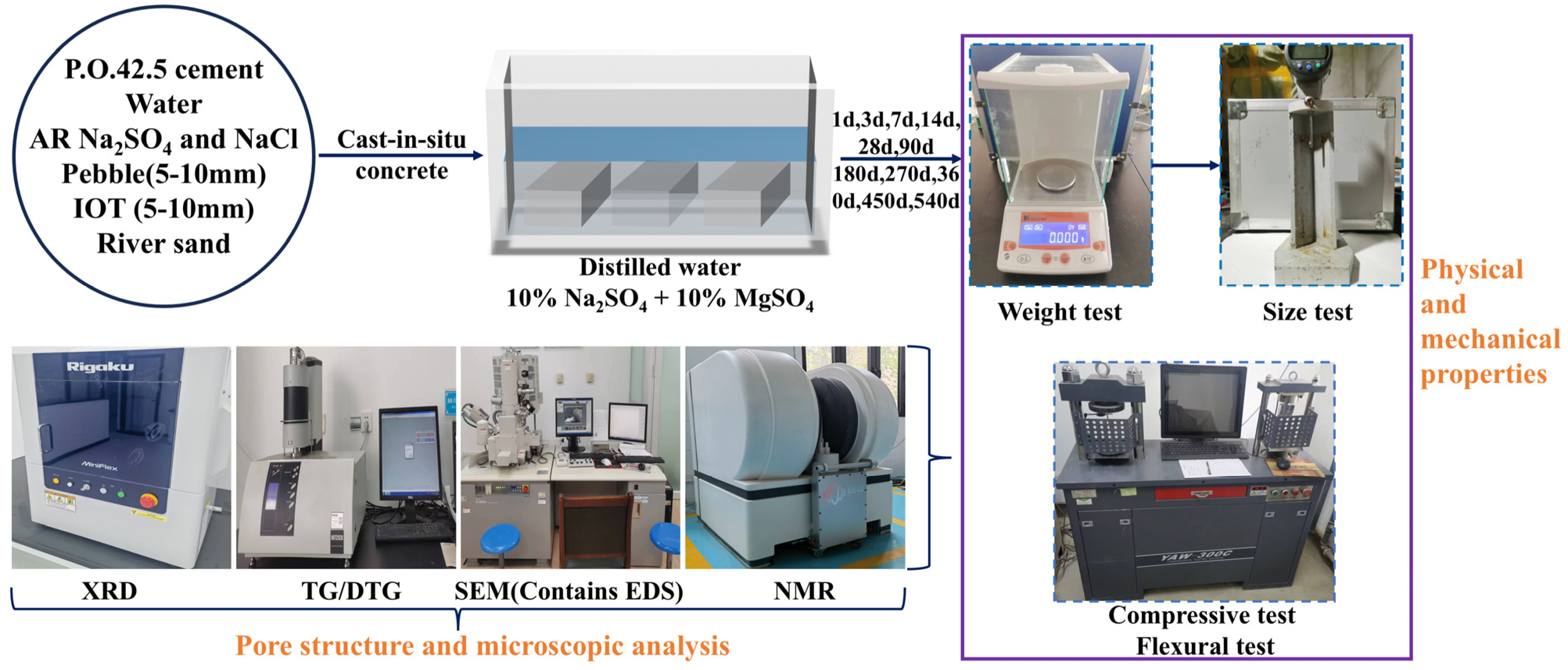
At corrosion ages of 1, 3, 7, 14, 28, 90, 180, 270, 360, 450, and 540 d, the macroscopic morphology of the specimens was observed, and their physical properties, mechanical properties, and pore structure characteristics were evaluated. The measured parameters included changes in mass and size, flexural strength, compressive strength, and pore structure evolution. At the corresponding testing age, representative samples were collected for SEM, EDS, XRD, and TG analyses. A schematic illustration of the experimental program is provided in Figure 2.

2.3.1. Mass and Size

Specimens with dimensions of 40 mm × 40 mm × 160 mm were used for the evaluation of appearance, mass variation, and size change. Surface morphology was documented through photographic recording at different corrosion ages. Mass and size measurements were performed using an electronic balance and a length comparator, respectively, in accordance with GB/T 50082–2009 and GB/T 23439–2017 [30,31]. To quantitatively characterize the influence of IOT content on the evolution of specimen mass and size, the results were expressed in terms of variation rates calculated using Equation (1).
Δ L = L 0 L t L 0 × 100
In Equation (1), Δ L represents the rate of change in mass or size of specimen with different IOT contents, L0 represents the mass or size of the specimen before immersion, and Lt represents the mass and size of the specimen after t days of immersion.

2.3.2. Compressive and Flexural Strength

Compressive and flexural strength tests were conducted in accordance with GB/T 50081–2019 and GB/T 17671–2021 [32,33] using a microcomputer-controlled electronic compression-flexure testing machine. Cube specimens with dimensions of 100 mm × 100 mm × 100 mm were used for compressive strength testing at a loading rate of 0.5 MPa/s, while prism specimens measuring 40 mm × 40 mm × 160 mm were used for flexural strength testing at a loading rate of 0.5 kN/s. To quantitatively evaluate the deterioration degree of cast-in situ IOT concrete under different corrosion conditions, the strength change rate and strength loss rate were calculated according to Equations (2) and (3).
Δ M = M t M t 1 M t 1
Δ M L = M t M 28 M 28
In Equations (2) and (3), ∆M represents the change rate of compressive or flexural strength under different IOT content conditions, Mt represents the average compressive or flexural strength of the specimen after t days of immersion, and Mt−1 represents the compressive or flexural strength of the specimen after t − 1 days of immersion. ∆Mt represents the loss rate of compressive or flexural strength under different IOT content conditions, and M28 represents the compressive or flexural strength of the specimen at 28 days of immersion.

2.3.3. Microscopic and Mineral Testing

The microstructural evolution of the specimens exposed to different corrosion environments was characterized using scanning electron microscopy with an S-4800 instrument (Hitachi, Tokyo, Japan). Corrosion products were identified through X-ray diffraction analysis using a Rigaku Miniflex 600 diffractometer (Rigaku, Tokyo, Japan) equipped with Cu Kα radiation, operated at 30 kV and 0.5 A with a scanning rate of 5°/min. Because of the large scan step size and scan speed in XRD, it is not possible to obtain sufficient information to perform reliable quantitative analysis or phase analysis based on the Rietveld method. To further verify the phase composition, thermogravimetric and derivative thermogravimetric analyses were carried out using a NETZSCH STA-449 thermal analyzer (NETZSCH, Selb, Germany) under a nitrogen atmosphere over a temperature range of 40–1000 °C. Based on previously published studies, the calcium hydroxide content was quantitatively determined from the TG/DTG results using Equation (4) [3].
m Ca ( OH ) 2 = 74 18 m 400 500 + 74 44 m 550 800
In Equation (4), m Ca ( OH ) 2 represents the percentage content of calcium hydroxide, m400–500 represents the mass loss in the TG curve between 400 °C and 500 °C, while m550–800 represents the mass loss in the TG curve between 550 °C and 800 °C.

3. Results

3.1. Mass and Size Changes

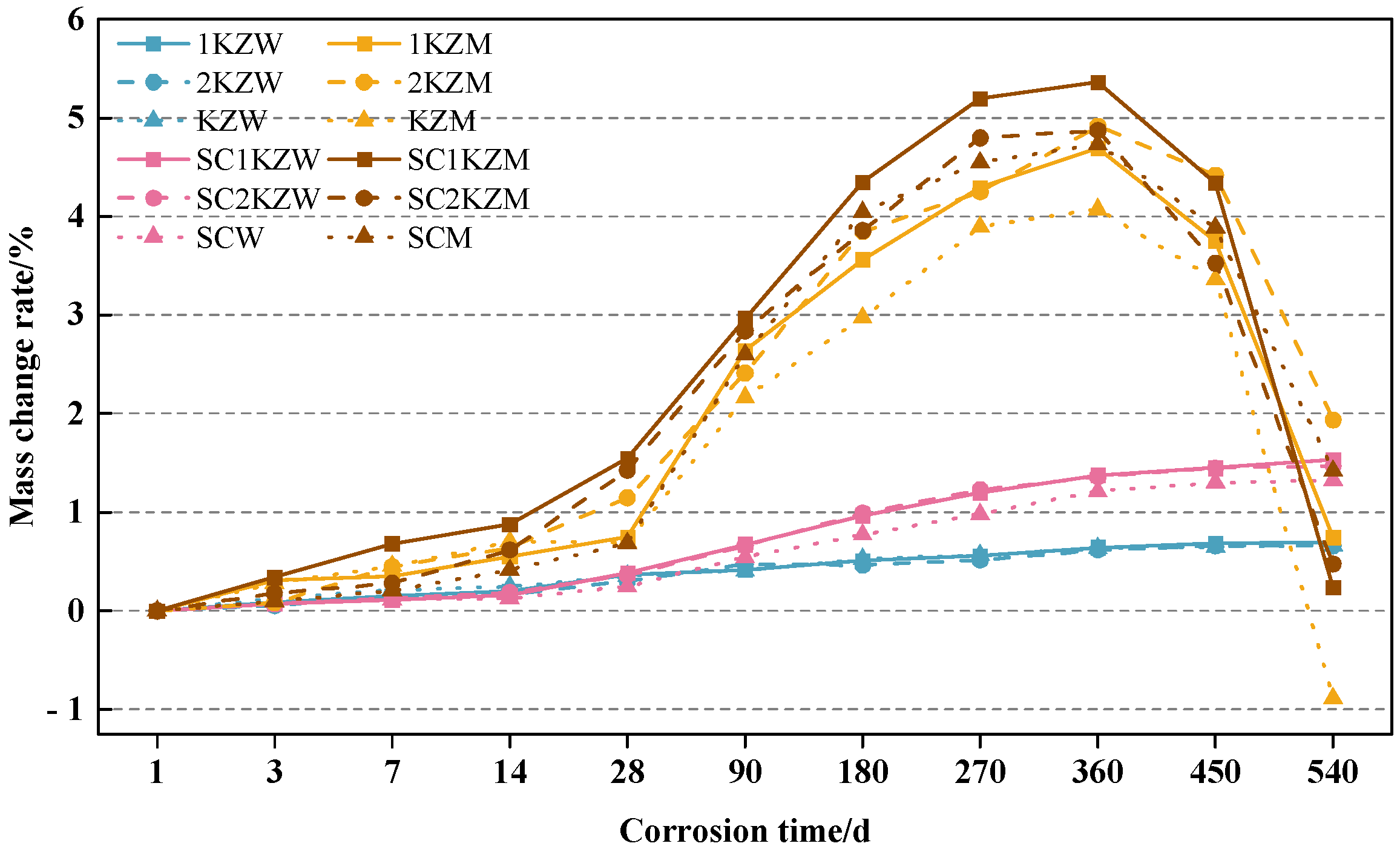
Figure 3 and Figure 4 show the rates of mass and size change in cast-in situ IOT concrete under different corrosive environments, respectively. As shown in Figure 3, the mass change in cast-in situ IOT concrete exhibited a clear dependence on both the corrosion environment and the IOT aggregate replacement level. During the early exposure period, especially before 90 d, all specimens showed a gradual increase in mass, but the magnitude of this increase varied markedly among different environments. Under distilled water immersion, the mass growth of KZW, 1KZW, and 2KZW remained relatively limited, with values generally below 0.5% at 90 d, indicating that the mass increase was mainly governed by continued cement hydration and slight pore filling. When internal salts were introduced under distilled water exposure, the mass increase became slightly higher, and SC1KZW and SC2KZW reached approximately 0.6–0.7% at 90 d, suggesting that internally supplied Cl and SO42− promoted the formation of Friedel’s salt and early ettringite within the matrix [34]. In contrast, specimens exposed to the external 10% Na2SO4 + 10% MgSO4 solution showed a much faster mass gain. At 90 d, KZM, 1KZM, and 2KZM reached mass change rates of 2.17%, 2.64%, and 2.41%, respectively, while the corresponding specimens with internal salts showed even higher values, exceeding 2.6%. This indicates that external Mg2+-SO42− attack was the dominant factor controlling early mass accumulation, whereas internal Cl-SO42− salts further intensified the process.
After 90 d, the difference among corrosion environments became more pronounced, and the mass evolution changed from slow accumulation to rapid expansion-induced growth followed by mass loss at later ages. In the external Mg2+-SO42− solution, KZM, 1KZM, and 2KZM reached peak mass change rates of 4.07%, 4.69%, and 4.91% at 360 d, respectively, whereas the coupled endogenous–exogenous corrosion condition still produced higher peaks. In particular, SC1KZM and SC2KZM exceeded 4.85% at 270–360 d, with SC1KZM reaching the highest value of 5.36%, confirming the strong synergistic deterioration caused by external Mg2+-SO42− ingress and internal Cl-SO42− release. The subsequent decline in mass after 360 d reflects the transition from product accumulation to cracking, surface scaling, and material detachment. This decline was most severe in the control specimens without IOT aggregate. The KZM decreased from 4.7% at 360 d to a negative value at 540 d, indicating serious spalling. By comparison, 2KZM still maintained a positive mass change of 1.94% at 540 d, suggesting that 50% IOT aggregate delayed late-stage peeling and helped preserve part of the damaged matrix. Under mild distilled water exposure, however, the influence of IOT content was much weaker, and 30% replacement showed a slightly more stable response, with limited mass growth and no obvious late-stage mass loss. Under internal salt exposure without external Mg2+-SO42− attack, 30–50% IOT replacement increased mass growth moderately but did not induce abrupt deterioration, indicating that IOT aggregate mainly affected ion transport and product accommodation rather than causing direct instability.
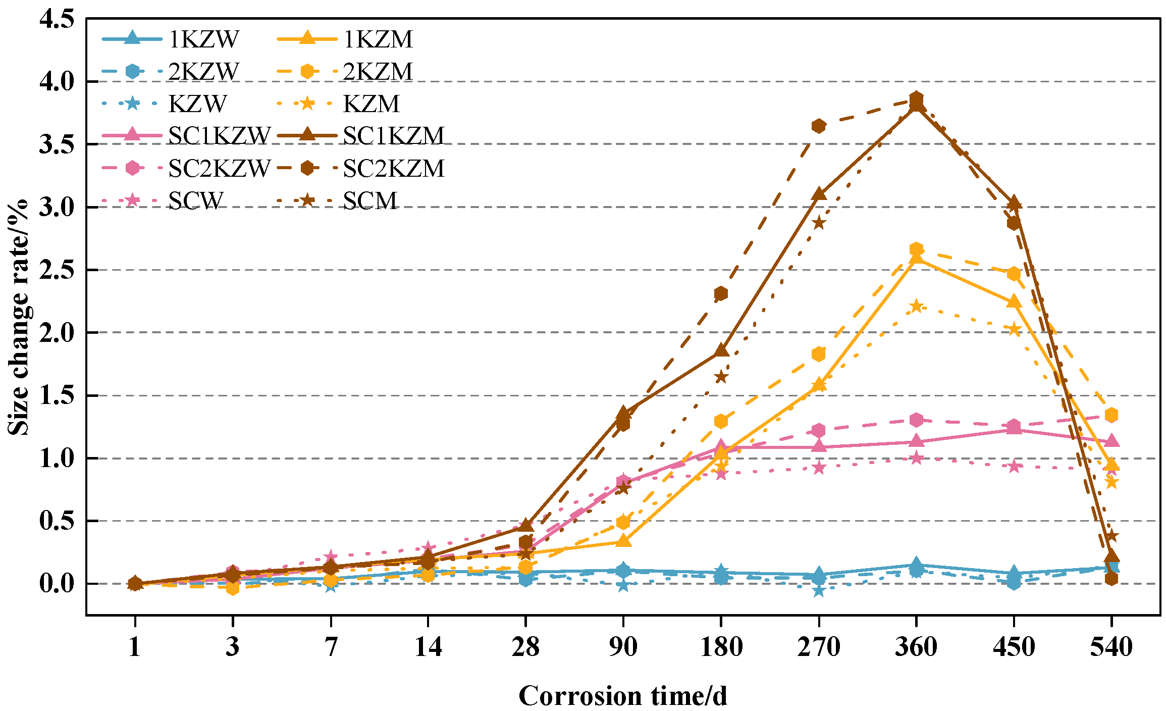
According to Figure 4, the size response of cast-in situ IOT concrete is less pronounced than the mass change at the early stage, but it becomes highly sensitive to the corrosion regime after prolonged exposure. Before 90 d, all specimens exhibit only slight expansion, and the size change rates of KZW, 1KZW, and 2KZW under distilled water immersion remain close to zero, generally lower than 0.1%. This indicates that the early mass increase observed in these specimens is mainly caused by continued hydration and pore filling, rather than by measurable macroscopic size expansion. A similar but slightly stronger response is observed in specimens containing internal Cl-SO42− salts under distilled water exposure. This suggests that internally generated Friedel’s salt and ettringite initially accumulate within available pores and interfacial transition zones without causing severe expansion damage. In contrast, the specimens exposed to the external 10% Na2SO4 + 10% MgSO4 solution display a clear expansion acceleration after 90 d, which corresponds well to the inflection point observed in the mass evolution (as shown in Figure 3). The SZM, SC1KZM, and SC2KZM reach 3.87%, 3.80%, and 3.86% at 360 d. This sharp increase is attributed to the combined formation of gypsum, ettringite, Friedel’s salt, and magnesium-bearing degradation products [35]. Unlike mass gain, which reflects both ion ingress and product deposition, size expansion directly reflects the accumulation of internal crystallization pressure. Therefore, the delayed but abrupt increase in size after 90 d indicates that corrosion products first fill the pore structure and then gradually exceed the accommodation capacity of the matrix, leading to expansive stress, microcracking, and macroscopic deformation.
Overall, the coupled evolution of mass and size indicates that IOT aggregate has an environment-dependent effect on corrosion damage. Under the endogenous corrosion environment, both mass gain and size expansion remain relatively limited, suggesting that 30% IOT replacement is sufficient to maintain size stability while accommodating hydration products and salt-related corrosion products. Under the exogenous Mg2+-SO42− corrosion environment, IOT incorporation increases mass accumulation, reflecting enhanced ion ingress and product deposition. However, the corresponding size expansion does not increase proportionally, especially at 50% replacement. Meanwhile, the mass results also show better residual mass retention after 360 d. Therefore, 30% IOT replacement is more appropriate for the endogenous corrosion environment, whereas 50% replacement is more beneficial under the exogenous Mg2+-SO42− corrosion environment and the endogenous–exogenous coupled corrosion environment because it could delay late-stage spalling.

3.2. Compressive Strength

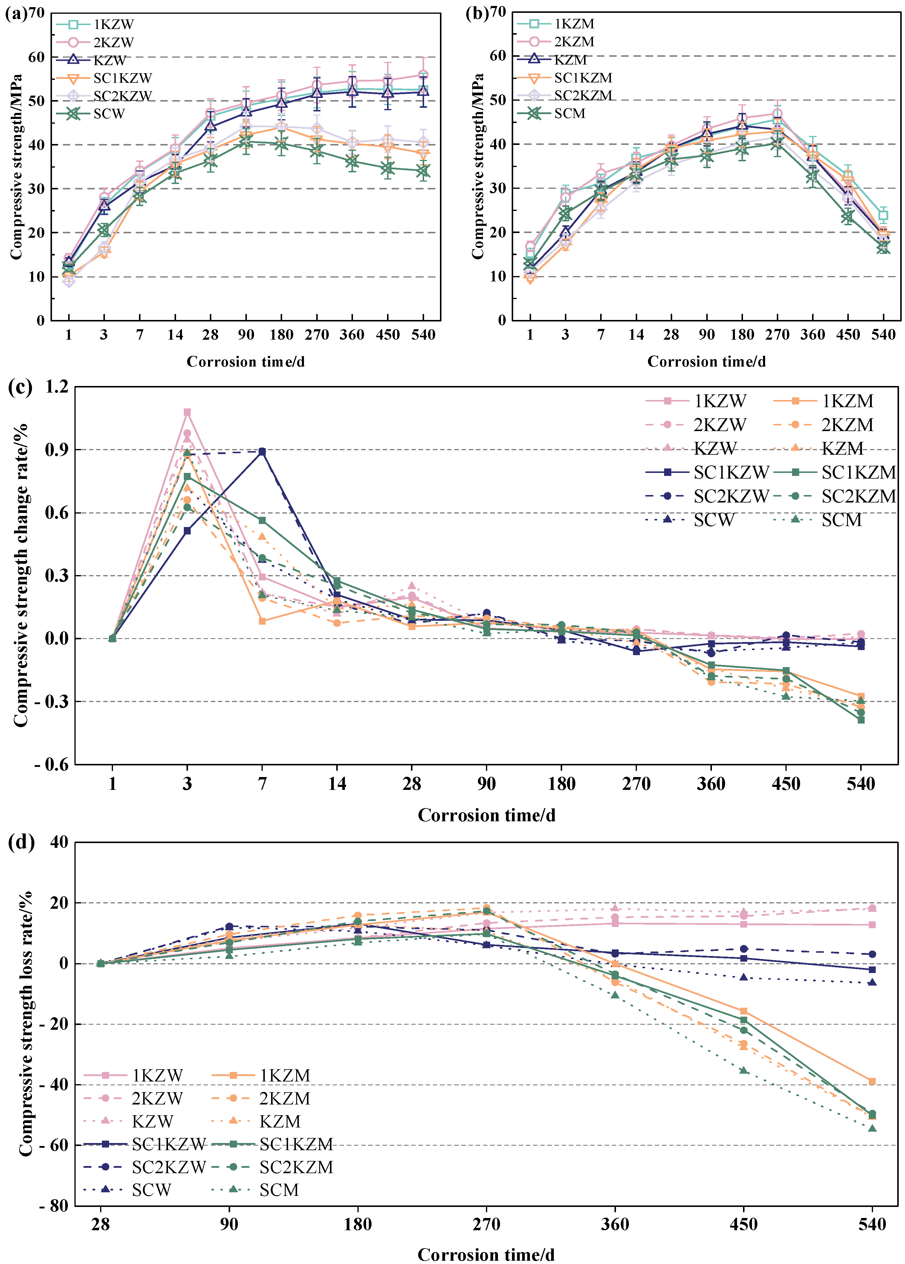
Figure 5 shows the compressive strength of specimens with different IOT contents under various corrosion environments. As shown in Figure 5a, the compressive strength of specimens immersed in distilled water increases continuously with exposure time. Compared with KZW, the 540 d strength of 1KZW and 2KZW increases by about 1.01% and 7.03%. This confirms that IOT aggregate does not reduce the bearing skeleton in distilled water. Instead, the rough surface and angular morphology of IOT aggregate contribute to mechanical interlocking and improve the aggregate mortar interface during continuous hydration [19]. When internal Cl and SO42− salts are present, the strength still increases in the early stage but shows a weaker development after 270 d. At 540 d, SZW, SC1KZW, and SC2KZW show strengths of approximately 34.13 MPa, 38.12 MPa, and 40.59 MPa, respectively. Compared with SZW, SC1KZW and SC2KZW increase by about 11.69% and 18.93%, respectively. This indicates that 50% IOT replacement provides the highest residual compressive strength under the endogenous corrosion environment. However, this strength advantage is not fully consistent with the mass and size results, where 30% replacement shows better stability against corrosion-induced expansion. This difference suggests that the beneficial effect of IOT aggregate depends on the evaluated index. The 30% replacement better controls deformation and product accumulation, whereas the 50% replacement provides a stronger residual aggregate skeleton and enhances load transfer after internal salt damage. Figure 5c further supports this interpretation. The strength change rate remains positive at early ages and then gradually approaches zero or becomes slightly negative after 180 to 270 d, showing that the early pore-filling effect of Friedel’s salt and ettringite gradually changes into internal stress accumulation and strength development stagnation.
Figure 5b shows that the specimens exposed to the exogenous Mg2+-SO42− corrosion environment and the endogenous–exogenous coupled corrosion environment present a typical increase followed by decrease in compressive strength. The turning point generally appears around 270 d, which is consistent with the mass and size results where rapid product accumulation and expansion become evident after 90 d and severe damage develops after 270 to 360 d. The peak strengths of KZM, 1KZM, and 2KZM were 43.30 MPa, 45.60 MPa, and 46.93 MPa, respectively. Among them, 2KZM exhibited the most favorable strength performance, with its peak strength being 8.38% higher than that of KZM. After 270 d, the strength decreases rapidly because gypsum and ettringite accumulation exceeds the pore accommodation capacity, while Mg2+ promotes C-S-H decalcification and the formation of non-cementitious M-S-H [36]. As shown in Figure 5d, which evaluates the compressive strength loss rate relative to the initial 28-day strength, most specimens exhibit an initial positive loss rate (early slight strength reduction or fluctuation) followed by a transition to negative values (strength gain) peaking around 90–180 d in the Mg2+-SO42− environments. This transition is clearly reflected in Figure 5c, where the strength change rate changes from positive to negative after 180 to 270 d and reaches a larger negative value at 360 to 540 d. Figure 5d further reveals that after 360 d, the strength loss rate accelerates sharply, dropping to −40% to −60% or lower by 540 d for most Mg2+-exposed specimens, confirming severe late-stage deterioration. Under the endogenous–exogenous coupled corrosion environment, the deterioration is more severe, but the IOT aggregate improves residual strength retention. SC2KZM shows higher late age strength than SZM and SC1KZM, indicating that 50% IOT replacement is more effective in preserving the load-bearing skeleton under multi-ion coupling attack. Notably, in Figure 5d, SC2KZM maintains a relatively lower strength loss rate in the later stage compared to other coupled corrosion specimens, further demonstrating the beneficial role of higher IOT replacement ratios in mitigating long-term strength degradation.

3.3. Flexural Strength

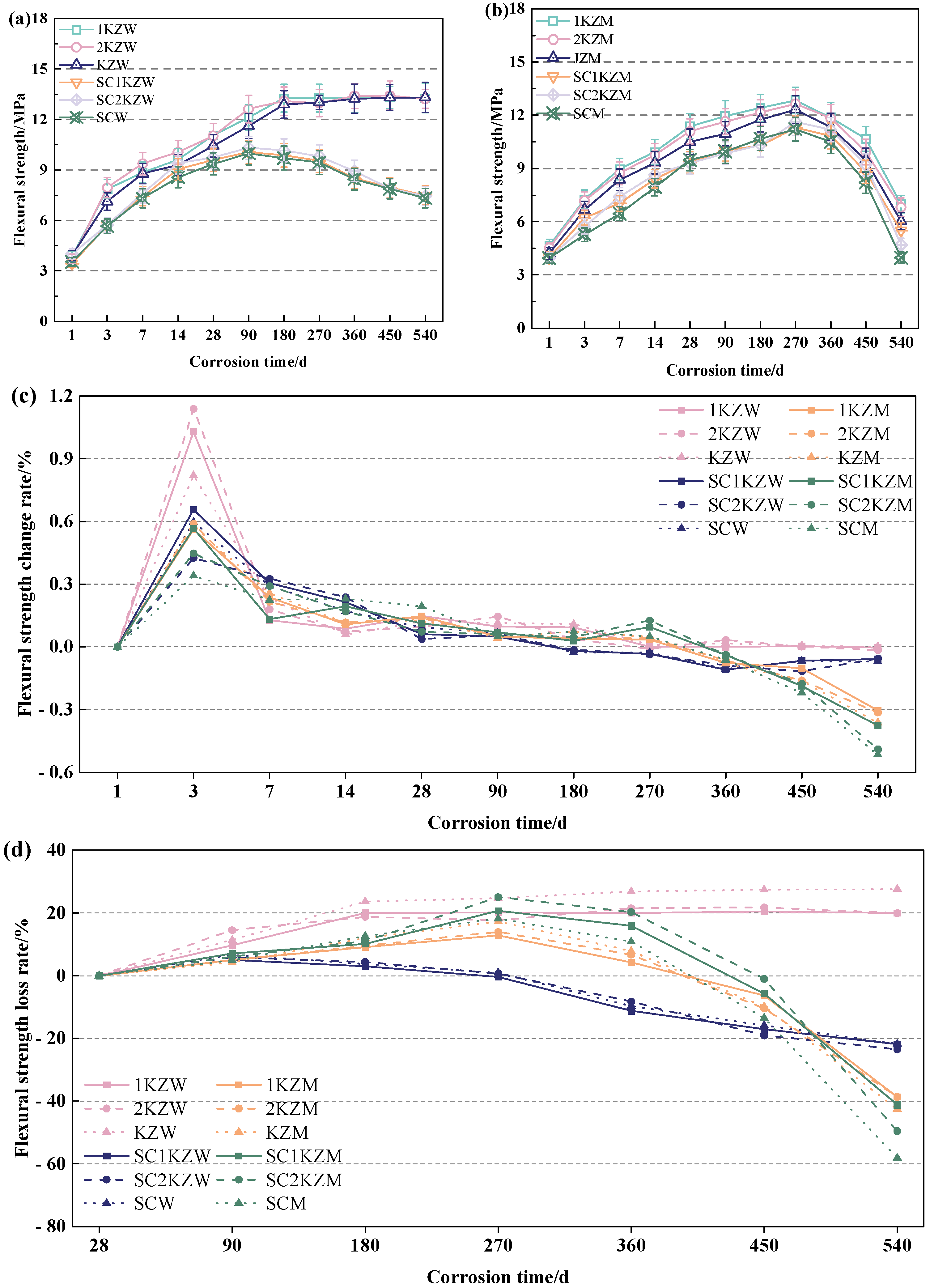
Figure 6 presents the flexural strength of specimens with different IOT contents under different corrosion environments. The results in Figure 6a indicate that the flexural strength of specimens exposed to distilled water and endogenous corrosion environments develops gradually with immersion time. In the distilled water group, KZW, 1KZW, and 2KZW maintain continuous strength growth throughout the exposure period, and their flexural strengths stabilize at 12.97 to 13.27 MPa after 270 d. The IOT-containing specimens show slightly higher values than the control specimen, indicating that IOT aggregate is beneficial to flexural resistance under non aggressive external exposure. This improvement is mainly related to the rough surface and angular morphology of IOT aggregate, which enhance aggregate mortar bonding and crack bridging capacity. For the endogenous corrosion group, SZW, SC1KZW, and SC2KZW also increase in the early stage, but their peak values are lower than those of the distilled water group and remain between 9.44 and 9.80 MPa. After 270 d, the flexural strength begins to decline slightly, which indicates that internally introduced Cl and SO42− gradually weaken the tensile zone and interfacial transition zone. Figure 6c further confirms this process. The strength change rate is highly positive before 7 d, with a maximum value of 1.14, suggesting rapid early strength development caused by hydration and initial pore filling. After 28 d, the change rate rapidly approaches zero, and the endogenous corrosion group turns slightly negative at later ages. Therefore, under distilled water exposure, IOT aggregate mainly improves flexural strength by strengthening the aggregate framework, whereas under the endogenous corrosion environment, 30% to 50% IOT replacement helps retain flexural capacity but cannot fully prevent the gradual deterioration caused by internal salt crystallization and corrosion products.
Figure 6b reveals a typical rise followed by a decline in flexural strength under the exogenous Mg2+-SO42− corrosion environment and the endogenous–exogenous coupled corrosion environment. Before 270 d, sulfate reaction products fill pores and temporarily densify the matrix, allowing the specimens under the exogenous corrosion environment to reach peak values of 12.32 to 12.84 MPa. Among them, the 30% IOT specimen generally shows the highest flexural strength, suggesting that moderate IOT replacement improves crack resistance without markedly increasing ion transport. As shown in Figure 6d, the flexural strength loss rate relative to the initial 28-day strength exhibits an early positive phase followed by a sharp transition to large negative values after 270–360 d. After 270 d, the flexural strength decreases sharply, and most specimens fall to about 4 to 7 MPa at 540 d. The negative strength change rates in Figure 6c, especially values from −0.31 to −0.52 at 540 d, confirm that the dominant process changes from product filling to cracking and spalling. Under the endogenous–exogenous coupled corrosion environment, the coexistence of internal Cl and SO42− with external Mg2+ and SO42− further accelerates tensile zone degradation, leading to lower late age flexural strength than that in the exogenous corrosion group [37]. Figure 6d further highlights that specimens under coupled corrosion suffer more severe loss rates (down to −50% or lower by 540 d), while 30–50% IOT replacement helps retain relatively better late-stage flexural performance under Mg2+-SO42− attack. Overall, the effect of IOT aggregate depends on the corrosion environment and the evaluation index. Under distilled water and endogenous corrosion environments, IOT aggregate improves or maintains flexural strength, with 30% replacement showing a more balanced response when size stability and strength retention are considered together. Under the exogenous Mg2+-SO42− corrosion environment, 30% replacement is also more favorable, whereas higher IOT content mainly contributes to residual skeleton stability under the endogenous–exogenous coupled corrosion environment but cannot fundamentally suppress late-stage flexural strength loss.

3.4. Pore Distribution

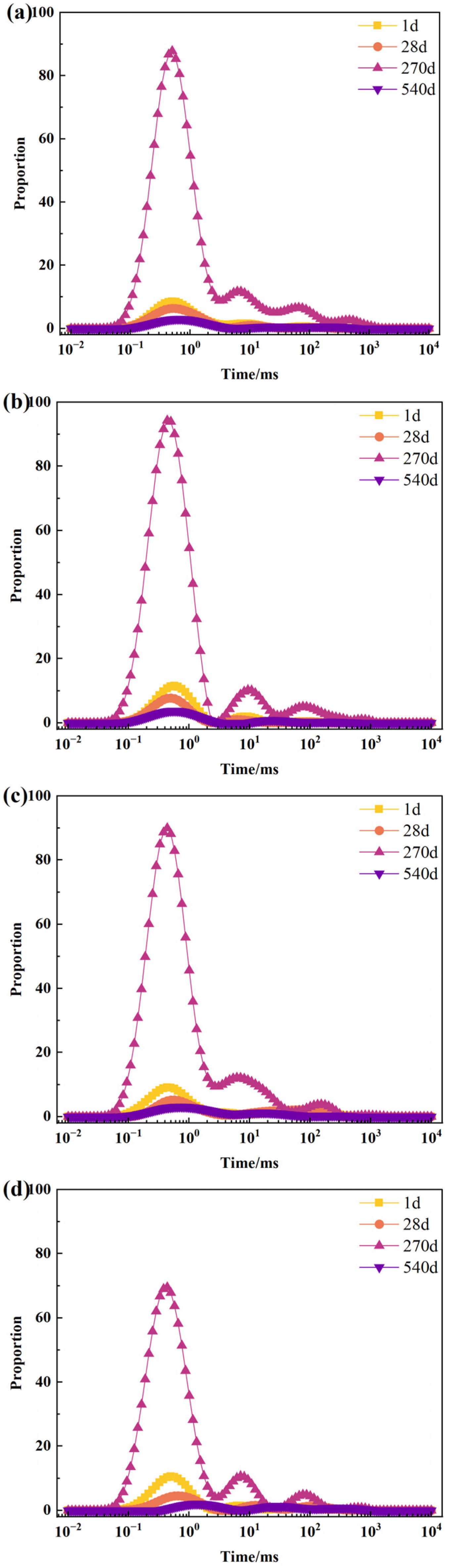
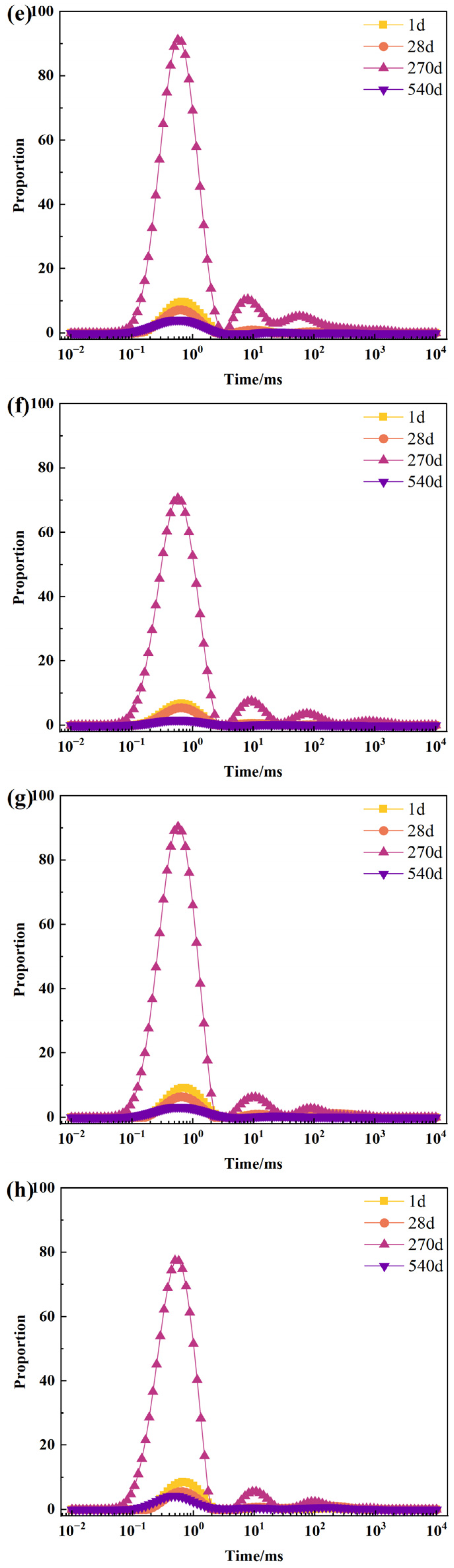
The pore structure evolution obtained from nuclear magnetic resonance testing is shown in Figure 7. The pore characteristics of cast-in situ IOT concrete are influenced by the IOT aggregate replacement level, corrosion environment, and exposure duration. Based on the adopted pore classification, the pores are divided into gel pores, transition pores, capillary pores, and macropores, corresponding to diameters of <10 nm, 10–100 nm, 100–1000 nm, and >1000 nm, respectively [21]. Figure 8 quantifies the pore size evolution under distilled water, endogenous corrosion, exogenous Mg2+-SO42− corrosion, and endogenous–exogenous coupled corrosion environments, providing evidence for the pore filling, coarsening, and damage development of cast-in situ IOT concrete under multi-ion corrosion. For all specimens, the pore signals are mainly concentrated in the short relaxation time region, indicating that gel pores and transition pores dominate the pore structure. At 1 d and 28 d, the relatively low and broad peaks suggest that the pore system is still developing. With increasing exposure time, the main peak intensity increases markedly at 270 d, generally reaching 70 to 95, which reflects significant pore refinement caused by continued hydration and corrosion product filling. This agrees well with the mass increase and the improvement in compressive and flexural strengths observed before or around 270 d. At 540 d, the main peak intensity decreases sharply, while the medium and long T2 components become more evident, particularly under Mg2+-SO42− attack and endogenous–exogenous coupled corrosion. This indicates a transition from pore refinement to pore coarsening, corresponding to late-stage strength degradation, mass loss caused by surface spalling and size reduction.
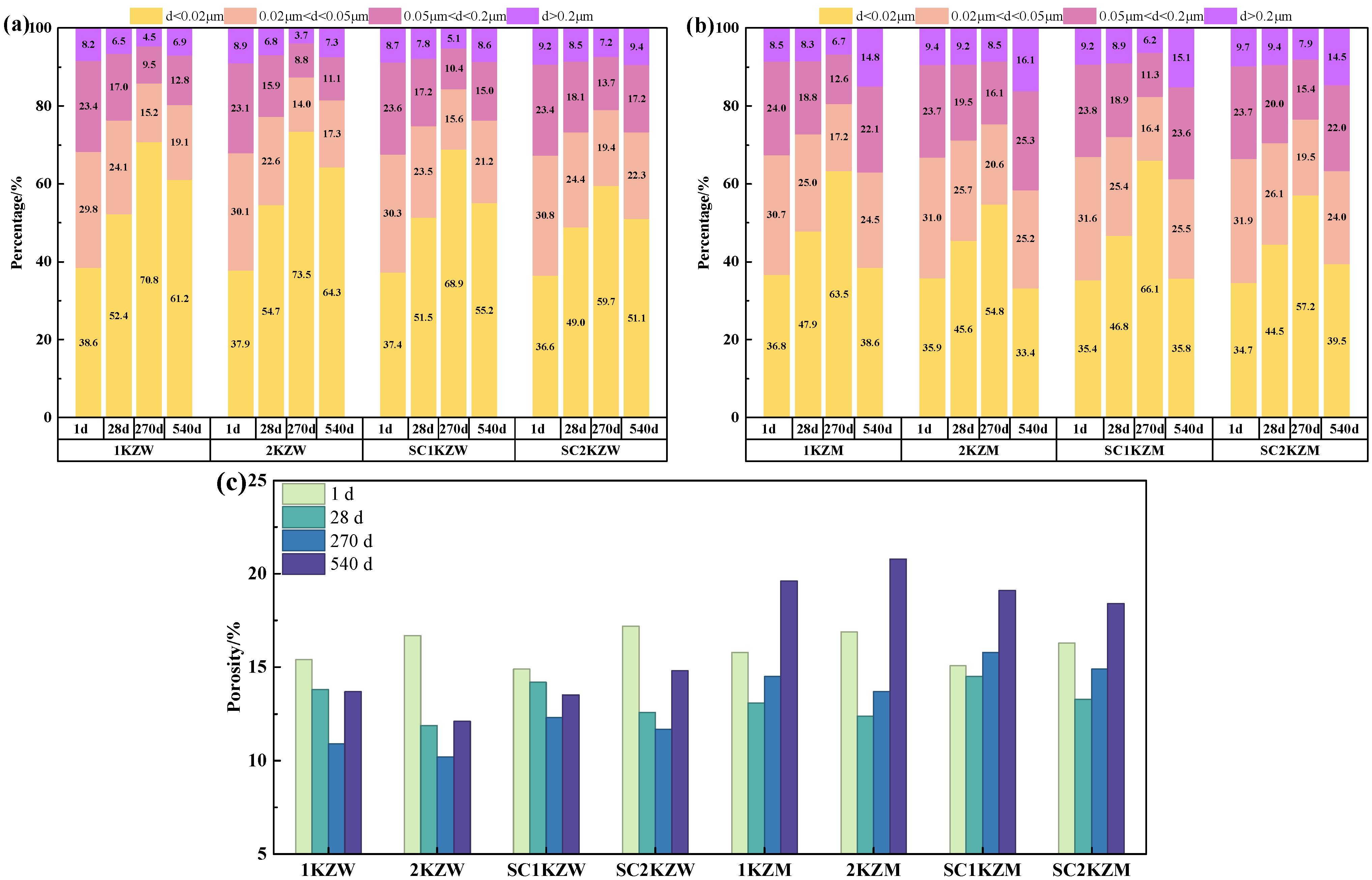
Figure 8 quantifies the pore size distribution derived from the NMR T2 spectra in Figure 7. In the distilled water and endogenous corrosion groups, the pore structure first becomes refined and then shows slight coarsening at 540 d. In Figure 8c, the total porosity of 1KZW decreases from 15.4% at 1 d to 10.9% at 270 d, then slightly increases to 13.7% at 540 d. For 1KZW, the gel pore proportion increases from 38.6% at 1 d to 70.8% at 270 d, while the combined proportion of capillary pores and macropores decreases from 31.6% to 19.7%, decreasing by 11.9 percentage points. This agrees with the continuous strength development and limited size change. Figure 8c further reveals that under exogenous Mg2+-SO42− corrosion, the total porosity of 2KZM rises markedly from 13.7% at 270 d to 20.8% at 540 d. In the endogenous corrosion group, SC1KZW shows a higher gel pore proportion than SC2KZW at 270 d, 68.9% versus 59.7%, with a difference of 9.2 percentage points, explaining the better size stability of 30% IOT replacement. Under exogenous Mg2+-SO42− attack and endogenous–exogenous coupled corrosion, pore coarsening after 270 d is more evident. Notably, Figure 8c indicates that SC2KZM maintains a relatively lower total porosity of 18.4% at 540 d compared to SC1KZM (19.1%), highlighting the advantage of 50% IOT replacement in mitigating severe pore coarsening under coupled corrosion. The gel pore proportion of 1KZM reaches 63.5% at 270 d, which is 8.7 percentage points higher than that of 2KZM, indicating a denser pore structure at 30% IOT replacement. At 540 d, the combined capillary pores and macropores of 2KZM increase to 41.4%, corresponding to late-stage strength loss, size reduction and mass decrease. For the coupled corrosion groups, SC2KZM (39.5%) retains a higher gel pore proportion than SC1KZM (35.8%) at 540 d, suggesting that 50% IOT helps preserve residual structural integrity under severe multi-ion attack. Overall, Figure 8 confirms that pore filling dominates before 270 d, while pore coarsening after prolonged corrosion governs the later deterioration of cast-in situ IOT concrete.

3.5. Microscopic and Mineral Analysis

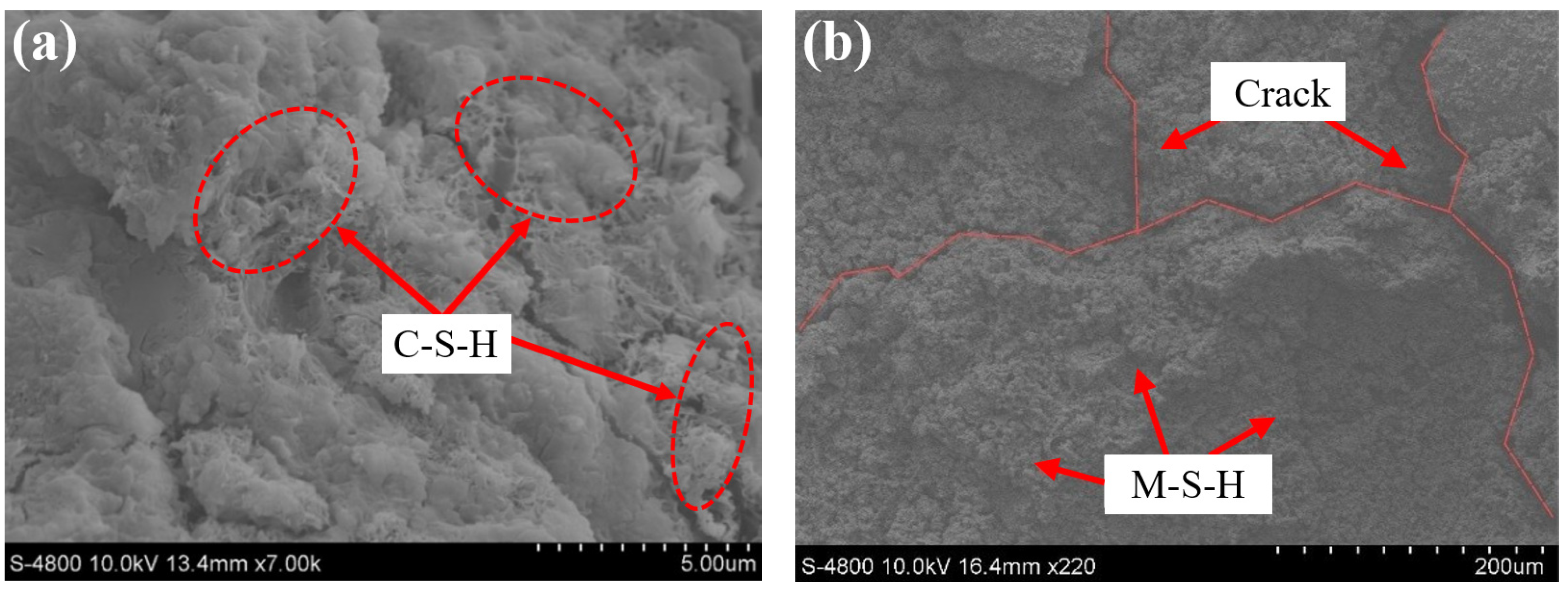
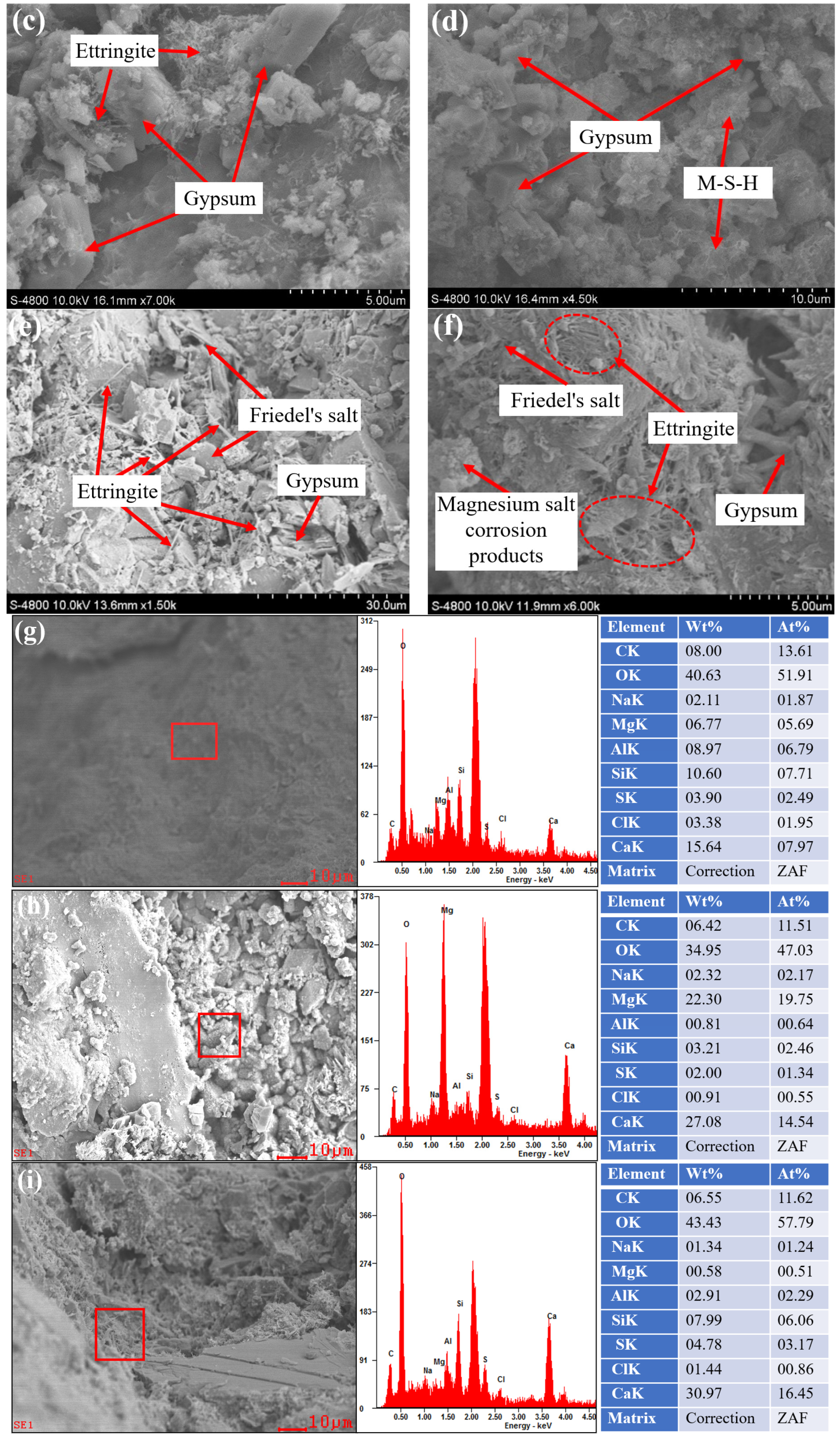
Figure 9 presents the SEM and EDS results of cast-in situ IOT concrete after corrosion exposure. According to Figure 9a, the 2KZW specimen has a relatively dense matrix with abundant C-S-H gel, indicating that continued hydration and hydration product filling refine the pore structure. This is consistent with the sustained strength development and limited size change under distilled water immersion. In the exogenous Mg2+-SO42− corrosion environment, visible cracks and loose M-S-H products are observed in 2KZM (Figure 9b), confirming that Mg2+ promotes C-S-H decalcification and weakens the cementitious matrix through the formation of M-S-H (Equation (10)). Meanwhile, gypsum is generated by the reaction between sulfate ions and calcium hydroxide or magnesium sulfate attack (Equations (5), (6) and (10)) [38,39]. This explains the late-stage strength loss and the increase in capillary pores and macropores identified by NMR. For the endogenous corrosion condition, ettringite and gypsum are detected in SC2KZW (Figure 9c), suggesting that internally introduced SO42− induces expansive product formation through sulfate reaction and ettringite formation (Equations (5) and (6)). These corrosion products initially fill pores and contribute to mass gain and strength development, but their continued accumulation leads to internal stress. Under endogenous–exogenous coupled corrosion, gypsum, ettringite, Friedel’s salt, M-S-H, and magnesium salt corrosion products are observed in SC1KZM and SC2KZM (Figure 9d–f), indicating that SO42−, Cl, and Mg2+ jointly control the deterioration process through coupled sulfate attack, chloride binding, and magnesium-induced decalcification (Equations (7) and (8)) [40,41]. The EDS spectra further identify O, Mg, Si, S, Cl, and Ca (Figure 9g–i), supporting the presence of sulfate-, chloride-bearing, and magnesium-rich corrosion products. These microstructural features explain the large mass accumulation and size expansion before the late stage, followed by pore coarsening, strength degradation, and surface spalling. The elemental compositions of corrosion products in SC2KZM specimens under endogenous–exogenous coupled corrosion were quantitatively analyzed by SEM-EDS at different ages (Figure 9g–i). In the early stage (Figure 9g), the matrix exhibits a Ca/Si atomic ratio of approximately 1.27 and a Si/Al ratio of 1.14, characteristic of mature C-S-H gel with partial incorporation of Al. With increasing corrosion duration, substantial changes occur due to decalcification and secondary product formation. At the intermediate stage (Figure 9h), the Ca/Si atomic ratio increases markedly to 5.96 while the Si/Al ratio rises to 4.03, indicating the formation of gypsum and magnesium hydrate as the dominant corrosion products, accompanied by relative Si enrichment in the residual matrix. In the late stage (Figure 9i), the Ca/Si atomic ratio decreases to 2.71 with a Si/Al ratio of 0.26, confirming pronounced decalcification of C-S-H into non-cementitious M-S-H gel together with continued gypsum precipitation, consistent with the porous morphology and strength degradation.
N a 2 S O 4 + C a O H 2 + 2 H 2 O C a S O 4 2 H 2 O + 2 N a O H
3 C a O A l 2 O 3 + 3 C a S O 4 2 H 2 O + 26 H 2 O 3 C a O A l 2 O 3 3 C a S O 4 32 H 2 O
2 2 C a O S i O 2 + 4 H 2 O 3 C a O 2 2 S i O 2 3 H 2 O + C a O H 2
12 C a O 7 A l 2 O 3 + 9 C a O H 2 + 7 C a C l 2 + 61 H 2 O 7 3 C a O A l 2 O 3 C a C l 2 10 H 2 O
M g 2 + + S O 4 2 + C a ( O H ) 2 + 2 H 2 O M g ( O H ) 2 + C a S O 4 2 H 2 O
C - S - H + M g S O 4 C a S O 4 2 H 2 O + M - S - H + M g ( O H ) 2
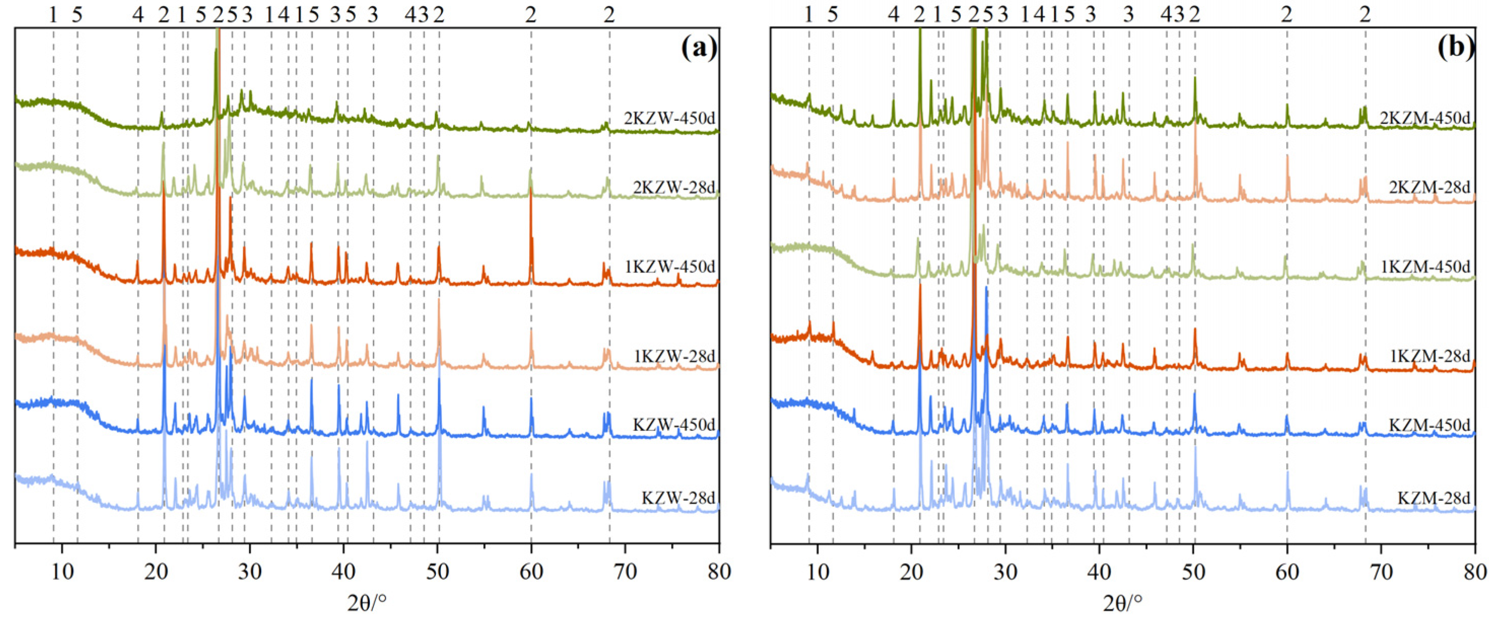
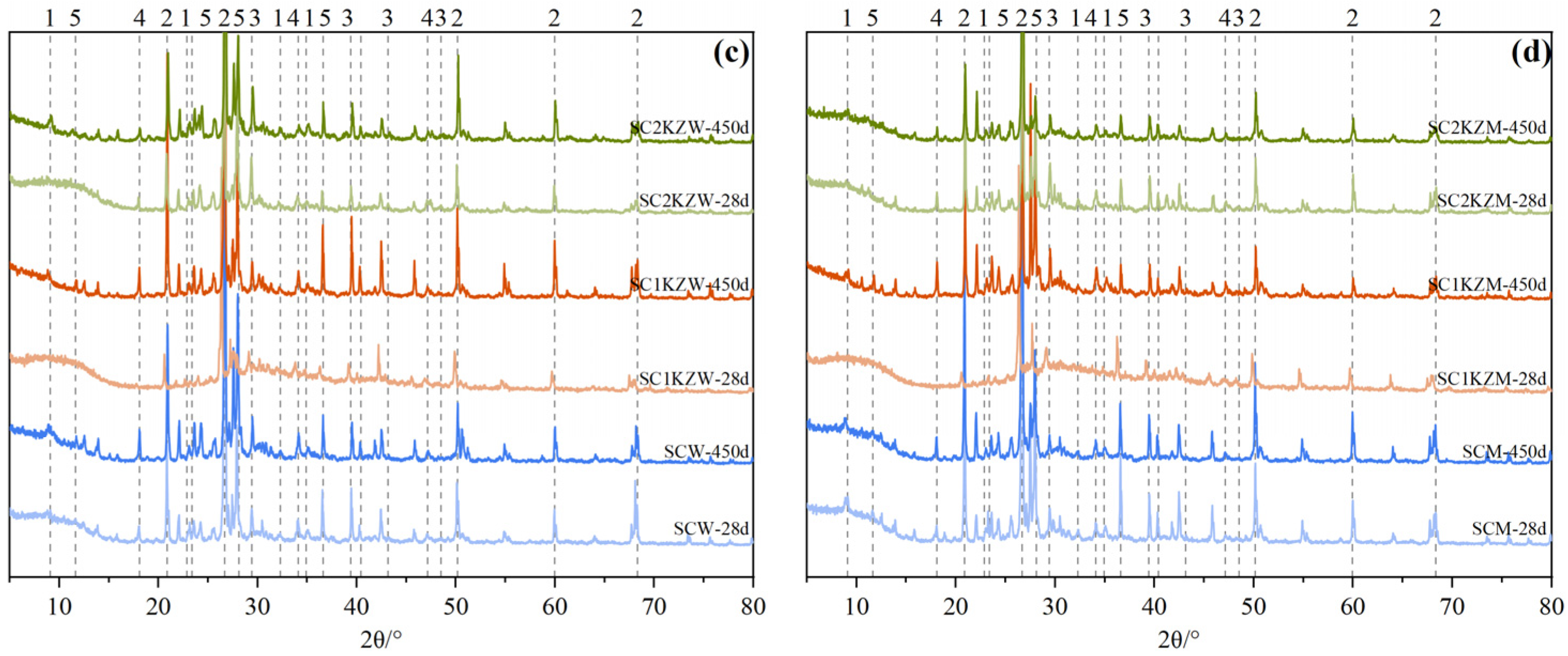
Figure 10 presents the XRD patterns of cast-in situ IOT concrete exposed to distilled water, exogenous Mg2+-SO42− corrosion, endogenous corrosion, and endogenous-exogenous coupled corrosion environments at 28 d and 450 d. In the distilled water group, the phase composition changes only slightly with exposure time, and the characteristic peaks of hydration products become more distinct at 450 d, indicating that continuous hydration remains the dominant process. No obvious intensification of expansive corrosion phases is observed, which explains the limited mass and size variations and the sustained strength development in this environment. Under exogenous Mg2+-SO42− attack, the peaks associated with gypsum and ettringite become stronger at 450 d, while the relative intensity of calcium-bearing hydration phases decreases, suggesting sulfate-induced expansion and Mg2+-driven decalcification of the cementitious matrix. This phase transformation corresponds to the formation of M-S-H and cracking observed in SEM, and provides a mineralogical basis for the later strength reduction and pore coarsening. In the endogenous corrosion group, the enhanced peaks of ettringite- and chloride-bearing phases at 450 d indicate that internally introduced SO42− and Cl participate in the formation of expansive and binding products, including ettringite and Friedel’s salt. These products contribute to early pore filling and mass gain, but their continued accumulation may generate internal stress. The endogenous-exogenous coupled corrosion group shows the most complex diffraction response, with more pronounced peaks related to gypsum, ettringite, Friedel’s salt, and magnesium-related products at 450 d. This confirms that SO42−, Cl, and Mg2+ jointly accelerate phase transformation, leading to product accumulation at the earlier stage and damage development after long-term exposure.
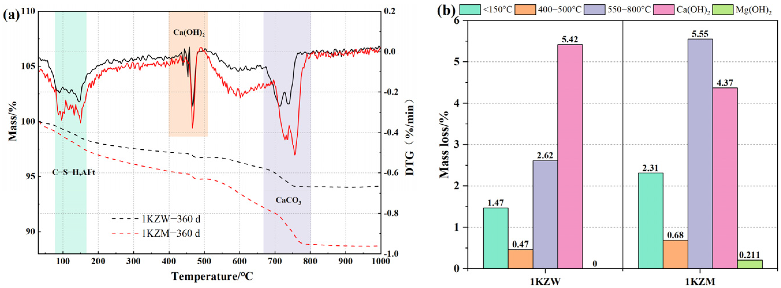
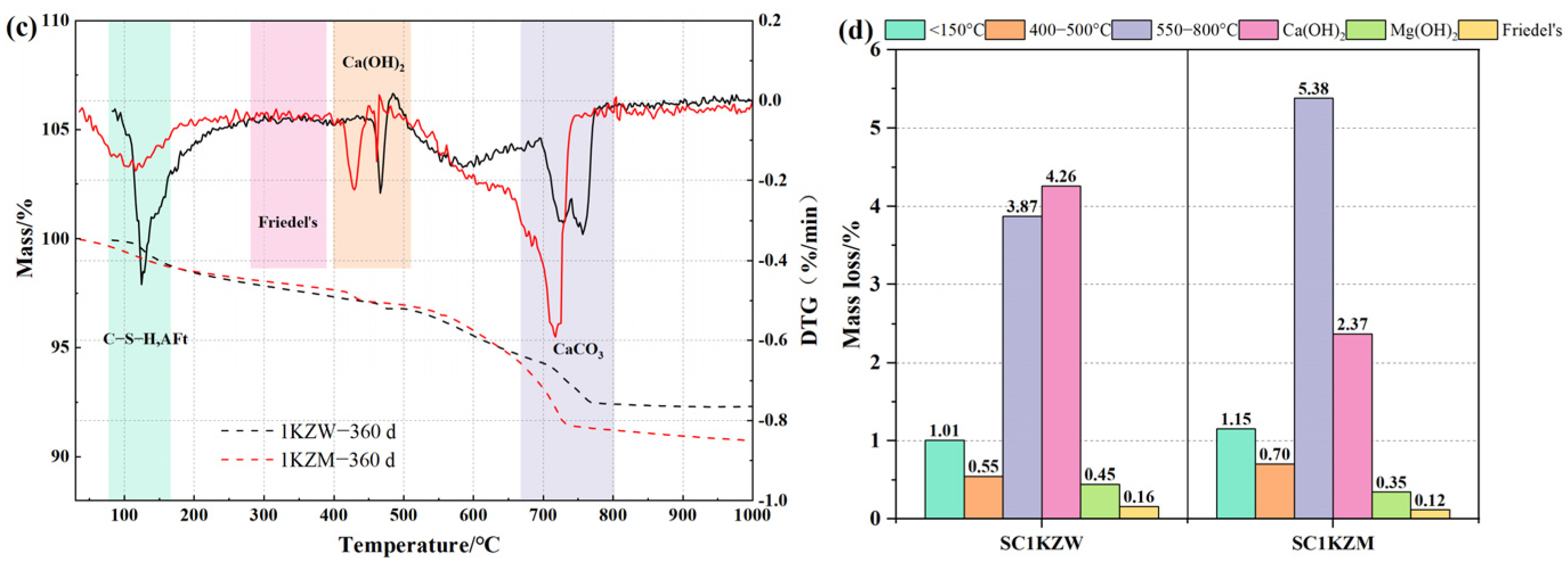
Figure 11 presents the TG and DTG results of cast-in situ IOT concrete at 360 d, with the corresponding mass losses summarized in Figure 11b,d. For specimens without internal salts, Figure 11a shows that 1KZM exhibits more pronounced mass loss than 1KZW below 150 °C and within the high-temperature range. As shown in Figure 11b, the mass loss below 150 °C increases from 1.47% in 1KZW to 2.31% in 1KZM, indicating that exogenous Mg2+-SO42− corrosion promotes the accumulation of bound water-bearing hydrates and poorly crystalline corrosion products. This corresponds to the mass gain and pore filling observed before severe degradation. Meanwhile, the Ca(OH)2-related mass loss decreases, while the high-temperature mass loss increases markedly, together with the appearance of Mg(OH)2 in 1KZM, suggesting portlandite consumption and the formation of magnesium-bearing and carbonate-related products. For specimens containing internal salts, Figure 11c displays decomposition signals related to Friedel’s salt and Ca(OH)2, confirming the participation of internal Cl and SO42− in the corrosion process. According to Figure 11d, the Ca(OH)2-related mass loss decreases from 4.26% in SC1KZW to 2.37% in SC1KZM, indicating stronger calcium consumption under endogenous–exogenous coupled corrosion. The increased high-temperature mass loss and the reduced Friedel’s salt-related loss further suggest that chloride binding is partly weakened by the competitive formation of sulfate- and magnesium-related products [42]. This explains the SEM and XRD observations of ettringite, gypsum, M-S-H and magnesium salt corrosion products in the coupled corrosion group. Therefore, the TG DTG results show that exogenous and coupled corrosion environments accelerate the redistribution of calcium-bearing phases and reduce the stability of hydration products, which contributes to late-stage strength degradation, size instability, and the increase in capillary pores and macropores.

3.6. Lifetime Prediction Model

To evaluate the long-term durability performance of IOT concrete under sulfate-related corrosion environments, a lifetime prediction model was established based on Equations (10)–(13) and the compressive strength evolution during the 540 d exposure period. As shown in Figure 5, all specimens exhibited an initial strength enhancement stage followed by a deterioration stage. The early increase in strength is mainly attributed to the filling effect of corrosion products and the continued hydration of cementitious materials, whereas the subsequent strength reduction results from the expansion of corrosion products, decalcification of hydration products, and progressive development of microcracks. Therefore, the peak compressive strength at 270 d was selected as the reference value for durability evaluation. A failure criterion corresponding to a 30% reduction in compressive strength was adopted for service-life evaluation. The fitting parameters, coefficients of determination and predicted lifetimes are summarized in Table 4.
R t = f t f 270
R t = A e B t
R t = 0.75
t s = ln ( A / 0.75 ) B
where ft is the compressive strength at exposure age (t), and f270 is the peak compressive strength measured at 270 d. A and B are regression coefficients characterizing the deterioration rate of concrete under different corrosion environments. ts is the predicted lifetime.
The fitting results exhibit satisfactory correlation coefficients (R2 = 0.907−0.986), indicating that the exponential decay model can effectively describe the deterioration behavior of IOT concrete during the late corrosion stage. The parameter (B), which represents the deterioration rate, varies significantly among different mixtures and exposure conditions. A lower (B) value corresponds to a slower degradation process and therefore a longer predicted service life. Under sulfate–magnesium attack, the control specimen (JZM) exhibited a predicted lifetime of 387.1 d. When 30% of the natural aggregate was replaced by IOT aggregate, the predicted lifetime increased to 409.4 d, representing an improvement of approximately 5.8%. However, further increasing the replacement ratio to 50% reduced the predicted lifetime to 371.3 d. This result indicates that moderate incorporation of IOT aggregate provides the optimum balance between pore refinement and matrix integrity under sulfate–magnesium attack. Excessive replacement may increase interfacial heterogeneity and partially offset the beneficial effects of microstructural densification. For internal and external coupled sulfate–magnesium attack, the deterioration rate was generally higher than that under sulfate attack alone because of the combined effects of sulfate ions, magnesium ions, and expansive corrosion products. The control specimen (SCM) exhibited the shortest predicted lifetime of 369.3 d. Incorporation of 30% IOT significantly improved the resistance to coupled corrosion, extending the predicted lifetime to 403.4 d. The specimen containing 50% IOT also showed a longer lifetime than the control group, reaching 381.2 d. These results indicate that IOT aggregate effectively mitigates the transport of aggressive ions and delays the development of corrosion-induced damage.
It should be noted that the predicted lifetimes obtained in this study are based on accelerated corrosion conditions involving high-concentration sulfate–magnesium solutions. Therefore, these values should be regarded as relative durability indicators rather than direct estimates of actual field service life. Nevertheless, the prediction results provide an effective basis for comparing the long-term durability performance of different mixtures under identical exposure conditions. Combining the lifetime prediction results with the compressive strength evolution, NMR pore structure characteristics, TG/DTG phase transformation, and SEM observations, it can be concluded that appropriate incorporation of IOT aggregate improves the durability performance of concrete by refining the pore structure, reducing harmful pore connectivity, and mitigating the deterioration of hydration products. Overall, the 30% IOT replacement level exhibits the most favorable durability performance under sulfate–magnesium attack, whereas replacement levels ranging from 30% to 50% are recommended for severe internal and external sulfate–magnesium environments.

4. Discussion

4.1. Correlation Analysis

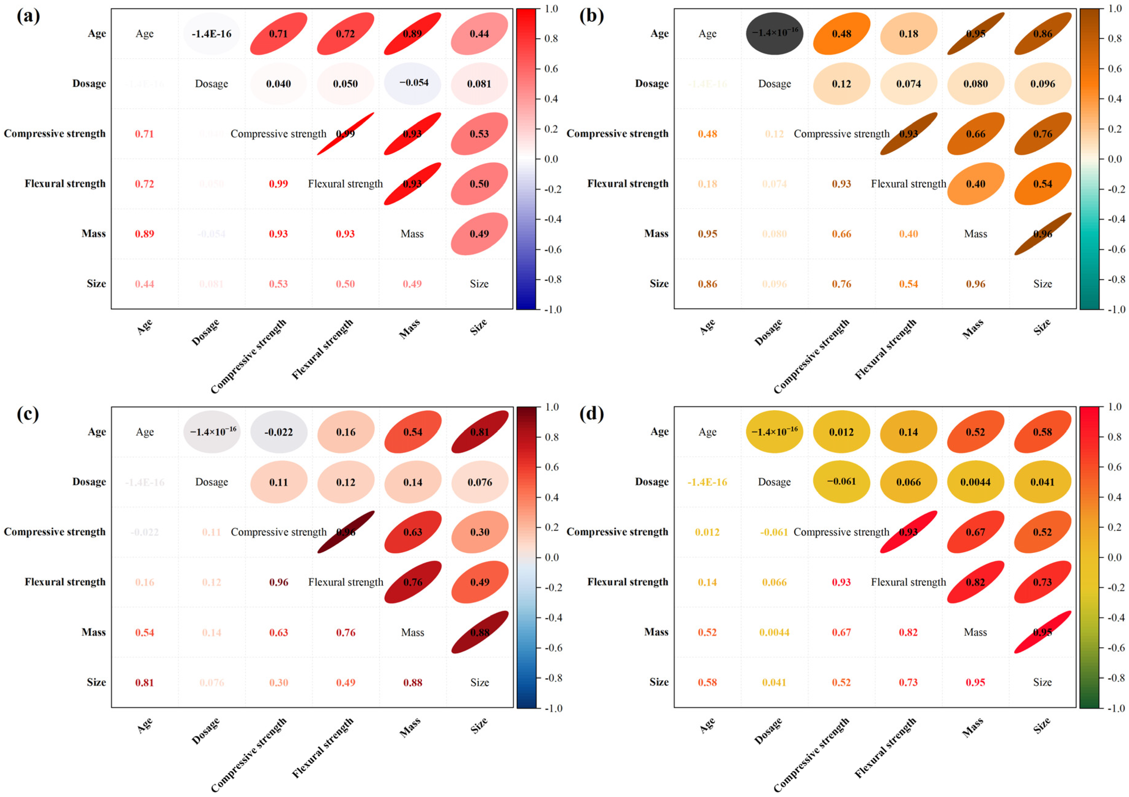
In distilled water and endogenous corrosion environments, the correlation results indicate that the performance evolution of cast-in situ IOT concrete is mainly governed by hydration, internal product formation, and pore refinement. In Figure 12a, age shows strong positive correlations with compressive strength, flexural strength, and mass, with coefficients of 0.71, 0.72, and 0.89, respectively, while its correlation with size is lower, at 0.44. This suggests that distilled water immersion mainly promotes strength development and mass gain through continued hydration, consistent with the dense C-S-H morphology and refined pore structure observed in SEM and NMR results. Physically, the increase in mass reflects the continuous formation of hydration products and the progressive filling of internal pores. This pore-filling effect reduces pore connectivity and enhances stress transfer between aggregates and mortar, thereby contributing to the simultaneous increase in compressive and flexural strength. The relatively weak correlation between age and size indicates that hydration-induced volume expansion is limited and does not significantly affect dimensional stability.
In Figure 12b, after internal Cl and SO42− are introduced, age is highly correlated with mass and size, with coefficients of 0.95 and 0.86, indicating that endogenous salts promote product accumulation and expansion. However, the dosage effect on strength remains weak, with coefficients of 0.12 for compressive strength and 0.074 for flexural strength. This supports the previous conclusion that 30% IOT mainly improves size stability and pore refinement, whereas 50% IOT contributes more to residual compressive strength through aggregate skeleton support. The strong mass–size relationship suggests that the accumulation of Friedel’s salt, ettringite, and other crystallization products gradually occupies pore space and generates local expansion stresses. At this stage, pore refinement and product filling still outweigh the detrimental effects of expansion, allowing strength development to continue despite slight dimensional growth.
Under exogenous Mg2+-SO42− corrosion and endogenous–exogenous coupled corrosion, the correlation between mass, size, and strength becomes more pronounced, showing that corrosion product accumulation and cracking dominate the deterioration process. In Figure 12c, mass is strongly correlated with size, with a coefficient of 0.88, confirming that sulfate and magnesium corrosion products directly contribute to expansion and later damage. This agrees with the SEM EDS, XRD, and TG DTG results, where gypsum, ettringite, M-S-H, Ca(OH)2 consumption, and high-temperature mass loss are observed. From a mechanistic perspective, the increase in mass initially results from the deposition of expansive corrosion products within the pore system. As corrosion progresses, the crystallization pressure generated by gypsum and ettringite exceeds the tensile resistance of the surrounding matrix, leading to microcrack initiation and propagation. Consequently, dimensional expansion becomes a precursor indicator of internal damage development. Simultaneously, Mg2+ accelerates the decalcification of C-S-H gel and promotes the formation of non-cementitious M-S-H phases, resulting in a gradual reduction in matrix cohesion and load-bearing capacity.
In Figure 12d, the coupled corrosion group shows the strongest mass–size correlation, with a coefficient of 0.95, while flexural strength is also closely related to mass and size, with coefficients of 0.82 and 0.73. These results indicate that tensile zone damage is highly sensitive to pore coarsening and expansive product accumulation [43]. The weak dosage correlations with compressive and flexural strength, −0.061 and 0.066, suggest that IOT replacement does not prevent corrosion reactions directly. Instead, 30% IOT provides a more balanced response under exogenous corrosion, while 50% IOT is more effective in maintaining residual skeleton stability under endogenous–exogenous coupled corrosion.

4.2. Deterioration Mechanism

Under endogenous corrosion, the deterioration of cast-in situ IOT concrete is mainly controlled by internally introduced Cl and SO42−. Since these ions are distributed inside the matrix from the initial stage, corrosion products are generated within pores and interfacial transition zones rather than only from the exposed surface. The mass and size results show moderate increases before the late stage, and the compressive and flexural strengths in Figure 3, Figure 4, Figure 5 and Figure 6 still increase at early and middle ages, indicating that internally formed products initially fill pores and improve compactness. This is supported by the NMR results in Figure 7 and Figure 8, where the gel pore proportion increases before 270 d, especially for SC1KZW. SEM EDS, XRD and TG DTG results further confirm the formation of ettringite, gypsum and Friedel’s salt. These products contribute to pore filling at the early stage, but their continuous accumulation generates crystallization pressure, causing microcracking and partial pore coarsening [44]. Therefore, 30% IOT replacement is more favorable for pore refinement and size stability, whereas 50% IOT improves late age residual compressive strength mainly through aggregate skeleton support and mechanical interlocking.
For exogenous Mg2+-SO42− corrosion, deterioration is governed by external ion ingress, sulfate reaction and Mg2+-induced decalcification. The higher mass gain and size expansion before 360 d indicate rapid deposition of corrosion products, which corresponds to the early strength increase shown in Figure 5 and Figure 6. However, this densification is temporary. SEM EDS reveals loose M-S-H and visible cracks, while XRD shows enhanced gypsum and ettringite peaks after long-term exposure. TG DTG results further indicate that Ca(OH)2 is consumed, with its related mass loss decreasing from 5.42% in 1KZW to 4.37% in 1KZM, while the mass loss below 150 °C increases from 1.47% to 2.31%. These results suggest that sulfate products fill pores at first, but continuous C-S-H decalcification and expansive product growth weaken the cementitious matrix. This explains the increase in capillary pores and macropores in Figure 8, as well as the late-stage strength loss, size reduction and mass decrease caused by cracking and spalling. In this environment, 30% IOT replacement provides a more balanced response because it improves interface bonding and crack resistance without excessively increasing ion transport pathways. The NMR results indicate that the 30% IOT mixture exhibits a lower proportion of harmful pores and a slower increase in macropores during the middle corrosion stage. Since the connectivity and size distribution of pores are closely related to ion migration pathways, these observations suggest that appropriate IOT incorporation may reduce the continuity of transport channels and delay the ingress of aggressive ions. Furthermore, SEM observations reveal fewer visible microcracks and a relatively denser matrix in the 30% IOT mixture compared with the reference concrete. Therefore, the proposed transport-resistance and crack-evolution mechanisms are supported by indirect microstructural evidence. However, it should be noted that transport coefficients, crack density, and crack connectivity were not directly measured in the present study. Consequently, the proposed mechanism should be regarded as a reasonable interpretation based on the available experimental results rather than a directly verified phenomenon.
The endogenous–exogenous coupled corrosion environment causes the most severe deterioration because internal Cl and SO42− interact with externally supplied Mg2+ and SO42−. In this case, corrosion products form both inside the matrix and along external ion ingress paths, resulting in simultaneous pore filling, expansion stress, and chemical decomposition of hydration products. At the early and middle stages, the formation of ettringite, gypsum, Friedel’s salt, M-S-H, and magnesium salt corrosion products promotes mass gain, size expansion, and temporary pore refinement. However, as these products continue to accumulate, their crystallization pressure exceeds the pore accommodation capacity, while Mg2+ further decalcifies C-S-H and consumes calcium-bearing phases [45]. This accelerates crack propagation, pore coarsening, surface spalling, and strength degradation at the late stage. Under this severe coupled condition, 30% IOT still contributes to middle-stage pore refinement, whereas 50% IOT better maintains residual structural integrity by improving damage accommodation and aggregate skeleton support, rather than by suppressing early corrosion reactions. The interpretation of the aggregate skeleton effect is primarily based on the residual mechanical performance observed under severe coupled corrosion conditions. Although all mixtures experience corrosion product accumulation, pore coarsening, and hydration product decomposition, the 50% IOT mixture retains comparatively higher compressive strength at the late stage. Considering the rough surface texture and angular morphology of IOT aggregate, a stronger aggregate interlocking effect and enhanced load-transfer capability may still be maintained after partial matrix deterioration. This behavior suggests that the aggregate skeleton contributes to sustaining residual load-bearing capacity when the surrounding cementitious matrix is progressively weakened. Nevertheless, direct characterization of interfacial deterioration and local stress redistribution was not performed in the present study. Therefore, the aggregate skeleton effect should be considered a plausible mechanism supported by the available mechanical and microstructural evidence rather than a directly demonstrated conclusion.
Under single sulfate corrosion conditions, the incorporation of 30% IOT produces a denser pore structure and more favorable particle packing effect than the control mixture. The refined pore network effectively reduces sulfate ingress while maintaining adequate structural integrity. However, when the replacement level increases to 50%, the higher amount of IOT aggregate introduces additional interfacial heterogeneity and local defects, partially offsetting the beneficial pore-filling effect. Consequently, the 30% IOT mixture exhibits the best durability performance under single corrosion conditions. In contrast, under coupled sulfate–magnesium attack, the deterioration process becomes significantly more complex because of the simultaneous action of sulfate ions, magnesium ions, and repeated crystallization stresses. Under these more severe exposure conditions, the higher IOT replacement level (50%) provides enhanced resistance by further refining the pore structure and reducing the connectivity of harmful transport channels, thereby slowing the penetration of aggressive ions into the concrete matrix. The NMR results indicate that the increase in harmful pores is effectively suppressed in the 50% IOT mixture during coupled corrosion exposure, while the TG/DTG and SEM analyses reveal relatively lower degrees of hydration product decomposition and microstructural deterioration. Therefore, the optimum replacement level shifts from 30% under single corrosion to 50% under coupled corrosion. It is worth noting that the shift in the optimum replacement level reflects a transition in the dominant deterioration mechanism. Under single sulfate corrosion, durability is mainly controlled by pore refinement and resistance to ion ingress, making the 30% IOT mixture more favorable. Under coupled sulfate–magnesium attack, however, matrix decomposition, expansive stress accumulation, and crack propagation become increasingly significant. In this case, the enhanced aggregate interlocking and residual skeleton support provided by the higher IOT content become more beneficial for maintaining structural integrity. Although this interpretation is consistent with the observed mechanical and microstructural results, future studies involving transport-property measurements, interfacial transition zone characterization, and crack-density quantification are required for further verification.

4.3. Feasibility Analysis

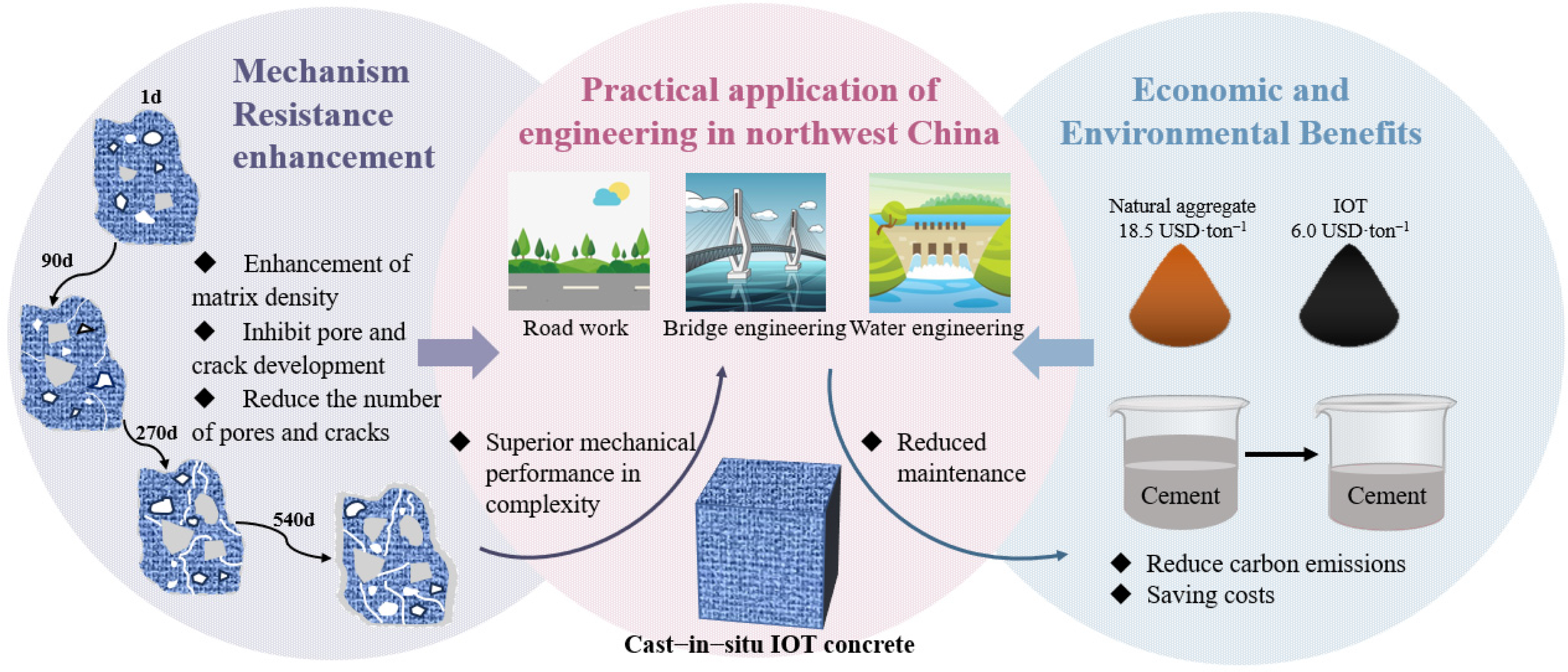
Figure 13 presents the engineering application feasibility of cast-in situ IOT concrete, including its deterioration resistance mechanism, potential application scenarios, and economic and environmental benefits. Based on the mechanical and microstructural results, cast-in situ IOT concrete demonstrates strong feasibility for engineering applications in salt lake and saline soil regions, particularly for roads, bridges, and hydraulic structures in northwest China. The strength data indicate that IOT aggregate functions beyond an inert replacement, actively contributing to the residual load-bearing skeleton. Under distilled water and endogenous corrosion conditions, specimens containing IOT maintain stable strength development, whereas under severe endogenous–exogenous coupled corrosion, higher IOT content enhances late-stage mass retention and delays surface spalling. This performance is attributed to the rough and angular morphology of IOT aggregate, which improves mechanical interlocking and strengthens the aggregate–mortar interface. NMR results reveal that appropriate IOT replacement promotes pore refinement during the middle corrosion stage, and SEM-EDS, XRD, and TG/DTG analyses confirm that corrosion products initially fill pores and densify the matrix before subsequent cracking and pore coarsening occur. These findings indicate that IOT aggregate enhances the damage accommodation capacity of cast-in situ concrete under complex corrosive conditions.
From an engineering and sustainability perspective, the benefits of IOT aggregate are substantial. A 30% IOT replacement is most suitable for environments dominated by either endogenous or exogenous corrosion due to balanced pore refinement and mechanical stability, whereas 50% replacement is advantageous under severe multi-ion coupled corrosion because it reinforces the residual skeleton. Economically, natural aggregate costs approximately 18.5 USD·t−1, while processed IOT aggregate is estimated at 6.0 USD·t−1, highlighting clear cost-saving potential. The above cost data were obtained from a market survey conducted in Shaanxi Province, China. Specifically, the prices represent the average monthly quotations provided by local aggregate suppliers and iron ore tailings processing enterprises during the investigation period. Although the actual costs may vary depending on transportation distance, local market conditions, and processing requirements, the reported values provide a representative basis for evaluating the economic feasibility of IOT utilization in regional engineering applications. For a concrete mixture containing approximately 1800 kg·m−3 of coarse aggregate, replacing 30% and 50% of natural aggregate with IOT can reduce aggregate material costs by approximately 6.75 USD·m−3 and 11.25 USD·m−3, respectively. In addition, the utilization of 30% and 50% IOT aggregate corresponds to the beneficial reuse of approximately 540 and 900 kg of iron ore tailings per cubic meter of concrete, while simultaneously reducing natural aggregate consumption by the same amounts.
Moreover, using IOT aggregate reduces reliance on natural stone, lowers tailings stockpiling pressure, and mitigates environmental impacts associated with aggregate extraction and transportation. Therefore, cast-in situ IOT concrete provides a durable, cost-effective, and environmentally sustainable solution for infrastructure in complex saline environments. Compared with conventional concrete, the proposed mixtures can decrease natural aggregate consumption by 30–50%, corresponding to a reduction of approximately 540–900 kg·m−3 of virgin aggregate extraction. Considering the superior durability observed under sulfate and coupled corrosion environments, the use of IOT aggregate may further reduce maintenance frequency and repair demand during service, thereby contributing to lower long-term infrastructure management costs in saline soil and salt lake regions.

5. Conclusions

This study investigated the mass and size change, mechanical properties, pore structure, microstructural characteristics, and mineral composition of cast-in situ concrete incorporating iron ore tailings aggregate under different corrosion environments. By comparing specimens with IOT aggregate replacement ratios of 0%, 30%, and 50%, the influence of IOT content on the corrosion resistance and deterioration mechanism of cast-in situ concrete under endogenous corrosion, exogenous Mg2+-SO42− corrosion, and endogenous–exogenous coupled corrosion conditions were systematically evaluated. The main conclusions are summarized as follows:
(1) The mass and size evolution of cast-in situ IOT concrete is mainly governed by the corrosion environment. Compared with distilled water exposure, exogenous Mg2+–SO42− attack and endogenous–exogenous coupled corrosion accelerates corrosion product accumulation and expansion deformation, while IOT incorporation improves late-stage mass retention and corrosion resistance.
(2) The mechanical properties exhibit an initial enhancement followed by gradual deterioration under aggressive environments. At 540 d, the compressive strengths of SC1KZW and SC2KZW reach 38.12 MPa and 40.59 MPa, which are 11.69% and 18.93% higher than SZW, respectively. Among all mixtures, 30% IOT replacement shows the most balanced mechanical and durability performance.
(3) NMR and microstructural analyses indicate that the pore structure undergoes refinement at early stages and coarsening during prolonged exposure. At 270 d, 1KZM exhibits the highest gel pore proportion, indicating a stronger pore-filling effect and denser microstructure at 30% IOT replacement. However, at 540 d, the combined proportion of capillary pores and macropores in 2KZM increases to 41.4%, demonstrating significant pore coarsening during long-term corrosion.
(4) The degradation of cast-in situ IOT concrete is controlled by the combined effects of corrosion product filling, expansive cracking, and matrix decalcification. Early-stage corrosion products temporarily densify the matrix, whereas prolonged exposure promotes pore coarsening and mechanical degradation.

Author Contributions

C.W.: Writing—original draft, Resources, Methodology. Z.C.: Investigation, Formal analysis, Resources. G.Z.: Writing—review and editing, Supervision, Methodology, Conceptualization. L.C.: Investigation, Formal analysis. L.Y.: Investigation, Formal analysis. G.G.: Investigation and Visualization. J.Z.: Supervision, Conceptualization, Formal analysis, and Investigation. H.F.: Resources, Formal analysis, Z.N.: Resources, Investigation and Formal analysis. All authors have read and agreed to the published version of the manuscript.

Funding

This research was financially supported by the National Natural Science Foundation of China (Grant No. 52378322, 56168035), the National Postdoctoral Program for Innovative Talents (No. BX20200287), the Key Research and Development Program of Shaanxi Province (2025CY-YBXM-156, 2025SF-YBXM-136, 2025-RCGC-01), and the Fundamental Research Funds for the Central Universities CHD (No. 300102213205).

Data Availability Statement

Data will be made available on request.

Conflicts of Interest

Authors Gang Gu and Jianfeng Zhu were employed by the company China Railway 20th Bureau Group Corporation (China). Author Zhibao Nie was employed by the company China Electric Power Research Institute. The remaining authors declare that the research was conducted in the absence of any commercial or financial relationships that could be construed as a potential conflict of interest.

Abbreviations

The following abbreviations are used in this manuscript:
IOTIron ore tailings aggregate
SEMScanning Electron Microscope
XRDX-ray diffraction
TG/DTGThermogravimetric/Derivative Thermogravimetric
NMRNuclear magnetic resonance
M-S-HMagnesium silicate hydrate
C-S-HCalcium Silicate Hydrate

References

  1. Yang, D.; Yan, C.; Liu, S.; Jia, Z.; Wang, C. Prediction of concrete compressive strength in saline soil environments. Materials 2022, 15, 4663. [Google Scholar] [CrossRef] [PubMed]
  2. Mei, X.; Zhang, Y.; Ni, D.; Yang, D.; SU, T. Analysis of the ion diffusion mechanism affecting the durability of concrete in saline-alkali soils in Western China. Constr. Build. Mater. 2025, 475, 141213. [Google Scholar] [CrossRef]
  3. Chen, Z.; Yue, L.; Huang, W.; Ding, S.; Zhao, G.; Bao, L.; Wei, F. Impacts of recycled aggregates on the degradation of in-situ repaired concrete induced by sulfate-magnesium and dry-wet combined attack. Colloids Surf. A Physicochem. Eng. Asp. 2026, 737, 139766. [Google Scholar] [CrossRef]
  4. Chen, Z.; Chen, L.; Zhao, G.; Ding, S.; Huang, W.; Zhu, J.; Yang, K.; Zhu, T.; Wei, F. Sustainable utilization of recycled aggregates in repairing concrete: Durability behavior under complicated sulfate-magnesium attack. J. Build. Eng. 2026, 120, 115457. [Google Scholar] [CrossRef]
  5. Zhao, G.; Hu, Y.; Li, S.; Wang, Z.; Guo, M.; Han, F.; Wang, H. Degradation mechanisms of chloride contaminated cast-in-situ concrete partially exposed to magnesium-sulfate combined environment. KSCE J. Civ. Eng. 2023, 27, 618–629. [Google Scholar] [CrossRef]
  6. Yue, L.; Wu, T.; Zhao, G.; Yang, K.; Ding, Y.; Zhu, T.; Wang, C.; Zhu, J. Enhancing mechanisms of cast-in-situ concrete durability against magnesium-sulfate-chloride multiple combined attack using iron tailing aggregates. J. Build. Eng. 2026, 119, 115217. [Google Scholar] [CrossRef]
  7. Yang, B.; Hu, X.; Li, A.; Zhao, T.; Sun, Y.; Fu, H. Degradation mechanism of cast-in-situ concrete under long-term sulfate saline soil attack. Constr. Build. Mater. 2025, 478, 141401. [Google Scholar] [CrossRef]
  8. Zhao, G.; Yuan, C.; Chen, Z.; Fang, Y.; Wang, C.; Bao, L.; Ding, S.; Wei, F. Durability of cast-in-situ concrete with partial replacement of coarse aggregate by iron tailings under complex combined corrosion of sulfates and chlorides. Constr. Build. Mater. 2026, 512, 145351. [Google Scholar] [CrossRef]
  9. Almada, B.S.; Melo, H.S.S.; Duarte, M.S.; Aguilar, M.T.P.; Garcia, D.C.S.; Silva, G.J.B.; Santos, W.J.D. Study of mechanical, durability and microstructural properties of cementitious composite with addition of different iron ore tailings from Brazil. J. Mater. Res. Technol. 2022, 18, 1947–1962. [Google Scholar] [CrossRef]
  10. Medina, C.; Zhu, W.; Howind, T.; de Rojas, M.I.S.; Frías, M. Influence of mixed recycled aggregate on the physical–mechanical properties of recycled concrete. J. Clean. Prod. 2014, 68, 216–225. [Google Scholar] [CrossRef]
  11. Yellishetty, M.; Karpe, V.; Reddy, E.H.; Subhash, K.N.; Ranjith, P.G. Reuse of iron ore mineral wastes in civil engineering constructions: A case study. Resour. Conserv. Recycl. 2008, 52, 1283–1289. [Google Scholar] [CrossRef]
  12. Amjad, H.; Abd-Elaal, E.S.; Ma, X.; Benn, T.; Fisher, M. A critical review of iron ore tailings as cement and aggregate substitutes for robust infrastructure: Mechanical, durability, eco-economic, and social impacts. J. Clean. Prod. 2025, 492, 144853. [Google Scholar] [CrossRef]
  13. Kuranchie, F.A.; Shukla, S.K.; Habibi, D.; Mohyeddin, A. Utilisation of iron ore tailings as aggregates in concrete. Cogent Eng. 2015, 2, 1083137. [Google Scholar] [CrossRef]
  14. Shettima, A.U.; Hussin, M.W.; Ahmad, Y.; Mirza, J. Evaluation of iron ore tailings as replacement for fine aggregate in concrete. Constr. Build. Mater. 2016, 120, 72–79. [Google Scholar] [CrossRef]
  15. Liu, Y.; Yang, G.; Zhang, S.; Cao, D.; Zhang, G.; Li, Z.; Zhang, C. A review on the resource utilization of iron tailings: Pathways, challenges, and prospects. Minerals 2026, 16, 455. [Google Scholar] [CrossRef]
  16. Zhao, J.; Ni, K.; Su, Y.; Shi, Y. An evaluation of iron ore tailings characteristics and iron ore tailings concrete properties. Constr. Build. Mater. 2021, 286, 122968. [Google Scholar] [CrossRef]
  17. Huang, X.; Tian, Y.; Jiang, J.; Lu, X.; He, Z.; Jia, K. Mechanical properties and enhancement mechanism of iron ore tailings as aggregate for manufacturing ultra-high performance geopolymer concrete. Constr. Build. Mater. 2024, 439, 137362. [Google Scholar] [CrossRef]
  18. Wang, J.; Li, X. Hybrid steel-polyethylene fiber-reinforced iron ore tailing concrete: Mechanical, sulfate freeze–thaw resistance, and microscopic characteristics. Buildings 2024, 14, 1843. [Google Scholar] [CrossRef]
  19. Fang, Y.; Qiao, L.; Hu, T.; Zhang, L.; Long, H.; Yu, F.; Yang, Z. Characteristics of iron ore tailings sand and properties of iron ore tailings sand concrete: A review. Int. J. Concr. Struct. Mater. 2025, 19, 41. [Google Scholar] [CrossRef]
  20. Hamada, H.M.; Al-Attar, A.; Askar, M.K.; Beddu, S.; Majdi, A. Enhancing sustainable concrete with iron ore tailings as fine aggregate: Environmental and engineering perspectives. Constr. Build. Mater. 2025, 470, 140707. [Google Scholar] [CrossRef]
  21. Zhao, G.; Chen, Z.; Peng, F.; Ding, S.; Wang, C. Utilization of tailing aggregates in cast-in-situ concrete: The enhancement in resistance to sulfate-chloride aggressive environment. J. Clean. Prod. 2025, 497, 145127. [Google Scholar] [CrossRef]
  22. Zhao, G.; Chen, P.; Ding, Y.; Nie, Z.; Bao, L.; Ding, S. Durability performance evaluation of iron tailings sand based concrete under combined corrosion of sulfate and magnesium salt. J. Build. Eng. 2025, 114, 114373. [Google Scholar] [CrossRef]
  23. Zhang, C.; Li, J.; Yu, M.; Lu, Y.; Liu, S. Mechanism and performance control methods of sulfate attack on concrete: A review. Materials 2024, 17, 4836. [Google Scholar] [CrossRef] [PubMed]
  24. Zhang, M.; Zou, D.; Qin, S.; Zhang, X.; Liu, T. Decoupling chemical and physical sulfate attack on OPC and L. SAC concrete under wet-dry cycles. J. Build. Eng. 2025, 99, 111637. [Google Scholar] [CrossRef]
  25. Belghali, M.; Ayed, K.; Ezziane, M.; Leklou, N. The influence of sulfate attack on existing concrete bridges: Study of external sulfate attack (ESA). Constr. Build. Mater. 2025, 483, 141751. [Google Scholar] [CrossRef]
  26. Zhao, Y.; Hu, X.; Yuan, Q.; Shi, C. The change of phase assemblage and desorption of bound chloride for seawater cement paste under sulfate attack. Cem. Concr. Compos. 2023, 139, 105033. [Google Scholar] [CrossRef]
  27. Zhao, G.; Ni, X.; Chen, Z.; Huang, W.; Ding, S.; Yang, K.; Zhu, J.; Wei, F.; Bao, L. A potential sustainable way for iron tailings sand in cast-in-situ concrete subjected to sulfate-chloride attack: Performance and mechanisms. J. Sustain. Cem. Based Mater. 2026, 15, 2059–2079. [Google Scholar] [CrossRef]
  28. Tian, Y.; Liu, Y.; Xie, Y.; Zhang, G.; Ye, H.; Yan, D.; Li, Y.; Li, B.; Xue, H.; Cai, Q. Coupled effects of chlorides and sulfates on steel reinforcement corrosion in concrete structures: A comprehensive review. Case Stud. Constr. Mater. 2025, 22, e04263. [Google Scholar] [CrossRef]
  29. Zhao, G.; Ding, Y.; Wang, C.; Ni, X.; Chen, L.; Zhang, C.; Bao, L.; Wei, F. Durability performance of cast-in-situ mortar containing iron tailings sand under synergistic internal-external sulfate, chloride, and magnesium attack. J. Sustain. Cem.-Based Mater. 2026, 15, 1915–1933. [Google Scholar] [CrossRef]
  30. GB/T 50082-2009; Standard for Test Methods of Long-Term Performanceand Durability of Ordinary Concrete. Standardization Administration of the People’s Republic of China: Beijing, China, 2009.
  31. GB/T 23439-2017; Expansive Agents for Concrete. Standardization Administration of the People’s Republic of China: Beijing, China, 2017.
  32. GB/T 50081-2019; Standard Test Methods for Physical and Mechanical Properties of Concrete. Standardization Administration of the People’s Republic of China: Beijing, China, 2019.
  33. GB/T 17671-2021; Test Method of Cement Mortar Strength. Standardization Administration of the People’s Republic of China: Beijing, China, 2021.
  34. El Inaty, F.; Marchetti, M.; Quiertant, M.; Metalssi, O. Chemical mechanisms involved in the coupled attack of sulfate and chloride ions on low-carbon cementitious materials: An in-depth study. Appl. Sci. 2023, 13, 11729. [Google Scholar] [CrossRef]
  35. Yang, Z.; Jiang, J.; Jiang, X.; Mu, S.; Wu, M.; Sui, S.; Wang, L.; Wang, F. The influence of sodium sulfate and magnesium sulfate on the stability of bound chlorides in cement paste. Constr. Build. Mater. 2019, 228, 116775. [Google Scholar] [CrossRef]
  36. Dewitte, C.; Lacarriere, L.; Neji, M.; Bertron, A.; Dauzères, A. Chemo-mechanical characterization of a low-pH model cement paste in magnesium bearing environment. Cem. Concr. Res. 2024, 184, 107598. [Google Scholar] [CrossRef]
  37. Li, X.; Jiang, G.; Wang, N.; Wei, Y.; Chen, Z.; Li, J.; Chen, B. Effect of chlorides on the deterioration of mechanical properties and microstructural evolution of cement-based materials subjected to sulphate attack. Case Stud. Constr. Mater. 2025, 22, e04235. [Google Scholar] [CrossRef]
  38. Campos, A.; López, C.M.; Aguado, A. Diffusion–reaction model for the internal sulfate attack in concrete. Constr. Build. Mater. 2016, 102, 531–540. [Google Scholar] [CrossRef]
  39. Geng, J.; Easterbrook, D.; Li, L.; Mo, L. The stability of bound chlorides in cement paste with sulfate attack. Cem. Concr. Res. 2015, 68, 211–222. [Google Scholar] [CrossRef]
  40. Wang, X.; Ni, W.; Jin, R.; Liu, B. Formation of Friedel’s salt using steel slag and potash mine brine water. Constr. Build. Mater. 2019, 220, 119–127. [Google Scholar] [CrossRef]
  41. Zhao, G.; Li, J.; Shi, M.; Cui, J.; Xie, F. Degradation of cast-in-situ concrete subjected to sulphate-chloride combined attack. Constr. Build. Mater. 2020, 241, 117995. [Google Scholar] [CrossRef]
  42. Shang, X.; Yue, X.; Pan, L.; Dong, J. Mechanisms and protection strategies for concrete degradation under magnesium salt environment: A review. Buildings 2026, 16, 264. [Google Scholar] [CrossRef]
  43. Wang, K.; Guo, J.; Liu, X.; Yang, L.; Zhang, P. Effect of dry–wet ratio on pore-structure characteristics of fly ash concrete under sulfate attack. Mater. Struct. 2021, 54, 100. [Google Scholar] [CrossRef]
  44. Ran, B.; Metalssi, O.; Chong, T.; Dangla, P.; Li, K. Pore crystallization and expansion of cement pastes in sulfate solutions with and without chlorides. Cem. Concr. Res. 2023, 166, 107099. [Google Scholar] [CrossRef]
  45. Liu, X.; Feng, P.; Yu, X.; Shen, X.; Geng, G.; Lothenbach, B. The physiochemical alterations of calcium silicate hydrate (CSH) under magnesium attack. Cem. Concr. Res. 2022, 160, 106901. [Google Scholar] [CrossRef]
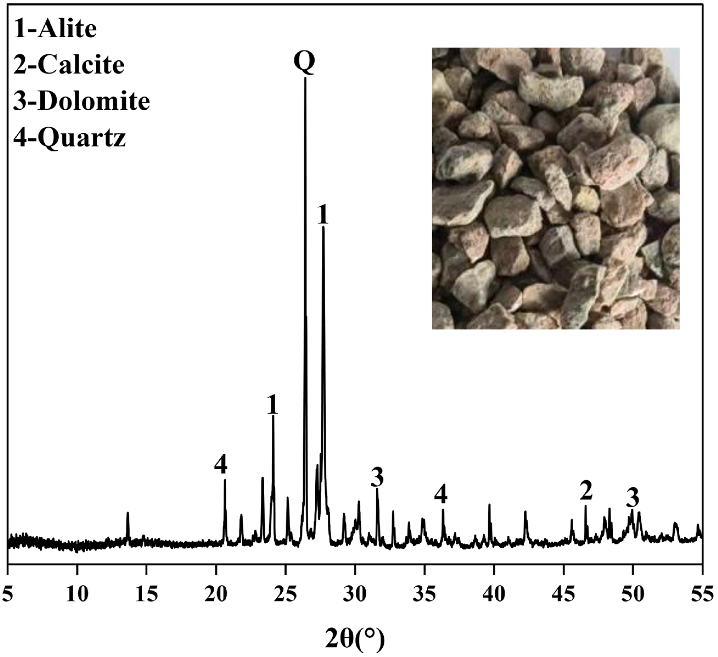
Figure 1. The apparent image of IOT and the XRD results.
Buildings 16 02436 g001
Figure 2. The test flowchart of cast-in situ iron tailings concrete.
Buildings 16 02436 g002
Figure 3. The mass change rate of cast-in situ IOT concrete under different corrosive environments.
Buildings 16 02436 g003
Figure 4. The size change rate of cast-in situ IOT concrete under different corrosive environments.
Buildings 16 02436 g004
Figure 5. The compressive strength of specimens with different IOT contents under various corrosion environments: (a) immersed in distilled water, (b) immersed in 10% Na2SO4 + 10% MgSO4, (c) strength change rate, (d) strength loss rate.
Buildings 16 02436 g005
Figure 6. The flexural strength of specimens with different IOT contents under various corrosion environments: (a) immersed in distilled water, (b) immersed in 10% Na2SO4 + 10% MgSO4, (c) strength change rate, (d) strength loss rate.
Buildings 16 02436 g006
Figure 7. The nuclear magnetic resonance results of the cast-in situ IOT concrete specimens: (a) 1KZW, (b) 2KZW, (c) 1KZM, (d) 2KZM, (e) SC1KZW, (f) SC2KZW, (g) SC1KZM, (h) SC2KZM.
Buildings 16 02436 g007aBuildings 16 02436 g007b
Figure 8. The distribution of pore ratios of cast-in situ IOT concrete specimens immersed in different corrosive environments: (a) immersed in distilled water, (b) immersed in 10% Na2SO4 + 10% MgSO4, (c) porosity variation.
Buildings 16 02436 g008
Figure 9. The SEM and EDS results of the cast-in situ IOT concrete specimens: (a) 2KZW, (b) 2KZM, (c) SC2KZW, (d) SC1KZM, (ei) SC2KZM.
Buildings 16 02436 g009aBuildings 16 02436 g009b
Figure 10. XRD patterns of the cast IOT concrete sample: (a) immersed in distilled water, (b) immersed in salt solution, (c) containing salt and immersed in distilled water, (d) containing salt and immersed in salt solution.
Buildings 16 02436 g010aBuildings 16 02436 g010b
Figure 11. The TG/DTG results of the cast-in situ IOT concrete specimens: (a) specimens 1KZW and 1KZM, (b) mass loss of specimens 1KZW and 1KZM, (c) specimens SC1KZW and SC1KZM, (d) mass loss of specimens SC1KZW and SC1KZM.
Buildings 16 02436 g011aBuildings 16 02436 g011b
Figure 12. Correlation results of cast-in situ IOT concrete under different corrosive environments: (a) immersed in distilled water, (b) containing salt and immersed in distilled water, (c) immersed in salt solution, (d) containing salt and immersed in salt solution.
Buildings 16 02436 g012
Figure 13. The engineering application of cast-in situ IOT concrete.
Buildings 16 02436 g013
Table 1. Chemical composition of P.O 42.5 grade ordinary silicate cement.
Chemical CompositionCaOSiO2Al2O3Fe2O3SO3MgOK2OTiO2Na2OOther
Content (%)67.2318.485.633.532.390.760.680.510.310.48
Table 2. Pebble and IOT main performance indicators.
Coarse Aggregate TypeApparent Density (kg/m3)Bulk Density (kg/m3)Water Absorption Rate (%)Crush Value (%)Clay Lump Content (%)
Pebble262115500.823.930.33
IOT266515110.697.040.03
Table 3. Concrete specimen name comparison table.
IDIOT ContentInternal EnvironmentExternal Environment
KZW0%NODistilled water
1KZW30%NODistilled water
2KZW50%NODistilled water
KZM0%NO10% Na2SO4 + 10% MgSO4
1KZM30%NO10% Na2SO4 + 10% MgSO4
2KZM50%NO10% Na2SO4 + 10% MgSO4
SCW0%3% NaCl + 3% Na2SO4Distilled water
SC1KZW30%3% NaCl + 3% Na2SO4Distilled water
SC2KZW50%3% NaCl + 3% Na2SO4Distilled water
SCM0%3% NaCl + 3% Na2SO410% Na2SO4 + 10% MgSO4
SC1KZM30%3% NaCl + 3% Na2SO410% Na2SO4 + 10% MgSO4
SC2KZM50%3% NaCl + 3% Na2SO410% Na2SO4 + 10% MgSO4
Table 4. Lifetime prediction results of IOT concrete under different corrosion environments.
SpecimenFitting EquationR2Predicted Life (d)Predicted Life (Year)
JZMRt = 2.158e−0.00273t0.964387.11.06
1KZMRt = 1.846e−0.00220t0.972409.41.12
2KZMRt = 2.268e−0.00298t0.986371.31.02
SCMRt = 2.365e−0.00311t0.985369.31.01
SC1KZMRt = 2.007e−0.00244t0.907403.41.11
SC2KZMRt = 2.164e−0.00278t0.966381.21.04
Disclaimer/Publisher’s Note: The statements, opinions and data contained in all publications are solely those of the individual author(s) and contributor(s) and not of MDPI and/or the editor(s). MDPI and/or the editor(s) disclaim responsibility for any injury to people or property resulting from any ideas, methods, instructions or products referred to in the content.