Article

MLLMto3D: An MCP-Driven Closed-Loop Framework for Architectural 3D Generation

1
College of Architecture and Urban Planning, Tongji University, Shanghai 200092, China
2
Shanghai Key Laboratory of Urban Renewal and Spatial Optimization Technology, Shanghai 200092, China
*
Author to whom correspondence should be addressed.
Buildings 2026, 16(12), 2437; https://doi.org/10.3390/buildings16122437
Submission received: 26 May 2026 / Revised: 15 June 2026 / Accepted: 16 June 2026 / Published: 18 June 2026
(This article belongs to the Section Construction Management, and Computers & Digitization)

Abstract

Multimodal large language models can read architectural images and design instructions but they still struggle to turn architectural rules into editable, executable models in professional modeling environments. To address this limitation, this paper presents MLLMto3D, an MCP-driven closed-loop framework that connects multimodal reasoning with Rhino-based modeling, feedback, and revision. The framework consists of five phases: visual parsing, JSON-based intent serialization, code synthesis, MCP-driven Rhino execution and feedback, and verification with bounded repair. Its core mechanism is JSON-based intent serialization, which converts image-derived architectural information into machine-readable modeling parameters under a predefined JSON schema. The schema separates geometric and compositional constraints, including height, bay rhythm, facade zones, and alignment rules, from design variables such as materials, openings, and ornament. Building on this mechanism, Skills modules externalize facade typology knowledge and safe Rhino scripting patterns, providing callable professional constraints for code synthesis to reduce design-intent deviation and API hallucination. The framework is evaluated through an experimental design case study on a site in Shanghai’s Hengfu Historic District, where the generation of new façades is informed by a nearby heritage architectural reference. The results show that MLLMto3D can generate a parametrically adjustable Rhino model while preserving the main compositional constraints, thereby advancing AI-assisted architectural 3D generation toward a controllable, verifiable, and iterative modeling process.

1. Introduction

Multimodal large language models can extract visual information from images and generate parametric code for CAD environments [1,2]. This does not mean that they are ready for architectural 3D modeling. Architectural models differ from general 3D objects: they must not only produce visual form, but also maintain clear geometry, editable parameters, and design intent such as height, bay rhythm, facade zones, and compositional order. Existing LLM-to-3D workflows are usually based on one-shot code generation. Their outputs can fail because of CAD API misuse, wrong arguments, or hallucinated functions, and natural-language design intent is rarely converted into stable geometric constraints [3,4,5].
The Model Context Protocol (MCP) offers a technical basis for addressing this problem. It standardizes communication between language agents and external modeling environments, allowing architectural 3D generation to be organized as a closed loop of generation, execution, feedback, and repair. In this setting, a modeling kernel such as Rhino is no longer only the endpoint of code execution. It also becomes a verification surface: generated scripts are executed, errors and geometric results are returned, and the system can revise the code within a bounded repair loop.
Applying MCP to architectural 3D generation still leaves three problems. The first is kernel instability: generated code must run reliably in a real CAD kernel and return actionable feedback when it fails [3,4,6]. The second is weak intent formalization: topological constants in architectural design, including height, bay rhythm, floor structure, and facade zones, cannot remain as prose descriptions; they must be encoded as machine-readable and verifiable geometric parameters. The third is implicit domain knowledge: architectural typology, facade composition rules, and Rhino API safety patterns cannot rely only on pretrained model knowledge, but need to be supplied as reusable modules [1,2].
This paper proposes MLLMto3D, an MCP-based closed-loop workflow for architectural 3D generation. The central hypothesis is that multimodal inputs can be converted into more stable architectural models if reference images and natural-language prompts are first serialized into structured intent files, then combined with architectural Skills modules for parametric code synthesis, and finally executed, verified, and repaired through MCP in Rhino. The study has three research objectives, each addressing one of the three problems: to construct an MCP-driven closed-loop workflow that addresses kernel instability through bidirectional generation-execution feedback; to propose a JSON-based intent serialization method that addresses weak intent formalization by separating topological constants from stylistic variables; and to externalize architectural typological knowledge and Rhino API safety patterns as reusable Skills modules that address implicit domain knowledge. These three mechanisms are examined together as a feasibility study, through a new-building design case on a plot adjacent to Shanghai’s Wukang Mansion.

2. Theoretical Background

2.1. LLM-Driven CAD 3D Modeling

LLM-driven CAD has moved from code translation toward feedback-based refinement. Early systems translated textual prompts into parametric scripts [1,2], while later work improved geometric fidelity and introduced explicit reward or evaluation signals instead of treating code generation as a one-shot process [4,5]. Surveys of tool-augmented LLMs and LLM-driven code generation in software engineering contextualize this shift toward feedback-rich workflows [6,7]. In parallel, neural radiance fields and their text-driven extensions have broadened the landscape of AI-driven 3D outputs [8,9,10], with related work on radiance-field editing and image-to-3D synthesis [11,12]. Shape representations and sketch- or text-driven 3D generation extend this trajectory [13,14,15], alongside mesh stylization and real-time field rendering [16,17,18]. Recent surveys characterize multimodal large language models and their evaluation [19,20], and LLM-empowered agents in such pipelines [21,22]. Across this trajectory, generation quality and optimization mechanisms have both improved.
These gains have concentrated on mechanical parts; architectural models pose a separate modeling problem. Mechanical objects can often be decomposed into a limited set of features, such as extrusions, holes, chamfers, and filets, and optimized through feature-level or geometry-level criteria [1,2]. Architectural facades pose a different modeling problem. They are structured compositions of floor zones, bay rhythms, facade hierarchies, material systems, openings, and decorative elements [23,24,25]. These components must remain editable and mutually consistent, while also responding to contextual or regulatory constraints in specific design tasks [26,27]. Reviews of AI-assisted architecture and urban design situate these requirements in broader generative-AI work [28,29,30].
Architectural 3D generation therefore requires structure-aware generation and execution-aware validation. LLM4CAD shows that models capable of handling simple CAD parts in zero-shot settings degrade as geometric complexity increases, while multimodal input becomes more important precisely when geometry is no longer trivial [1]. For architectural use, the unit of generation must shift from isolated features to structured facade compositions, where topological constants such as height, bay rhythm, and facade zones are separated from stylistic variables such as material, openings, and ornament. Validation must also move beyond visual or geometric fidelity to check whether the generated model preserves the intended structure and remains executable in a CAD environment. These requirements define the starting point for the present work.

2.2. Open-Loop Limitations in LLM-Based Parametric Modeling Workflows

Early architectural LLM workflows demonstrated feasibility while leaving output verification to a separate stage. Prototype systems that couple LLMs with Rhino-class modeling environments have shown that natural-language commands can be translated into parametric API calls [3]; reviews of computational design and AI in architecture trace the same trajectory [26,31,32]. Adjacent work spans heritage-oriented generative design [27,29], contextual integration of generative AI in urban settings [28,30], facade-level generative synthesis [33,34], and AI-supported BIM and low-carbon design pipelines [35]. However, these systems mainly treated the generated script as the endpoint of the workflow. Whether the script could execute correctly, whether it produced valid geometry, and whether the resulting model preserved the intended architectural structure were not checked inside the modeling environment. LLMto3D advanced this direction by splitting the task across three Rhino. Geometry agents (prompt deconstruction, code translation, and parametric reassembly) and by giving users parametric handles. Yet, it still lacked an error path from execution back to generation, and its performance degraded on out-of-distribution designs [3].
Later workflows added feedback that operated outside the CAD kernel. Text2BIM extended the multi-agent pattern into BIM and introduced a rule-based model checker to support iterative improvement. Yet, the checker operates against predefined rules rather than runtime geometric states. BIMgent went further by using multimodal LLMs as computer-use agents to operate a BIM GUI directly, achieving a 32% success rate compared with 0% for non-agent baselines. However, its feedback comes from GUI screenshots, not from the geometric state produced inside the modeling kernel. These systems therefore improve interaction and checking, but they do not close the loop at the level where geometric failure actually occurs.
The core limitation therefore lies at the kernel-level recovery layer. Parametric handles, rule-based checkers, and GUI screenshots each provide partial feedback, but none can directly capture runtime API errors, invalid objects, failed Boolean operations, or malformed geometry inside the CAD environment. As a result, a single API misuse or geometric failure can stop the workflow or propagate through the generated model without an in-pipeline repair mechanism [4,5]. For architectural 3D generation, where the output must be editable, structurally organized, and executable in a professional modeling environment, this open-loop pattern remains a major bottleneck. MCP, reviewed next, offers a communication mechanism for crossing this boundary.

2.3. MCP-Enabled Closed-Loop 3D Modeling Workflows

MCP turns tool use into a bidirectional modeling loop. Released by Anthropic in November 2024, the Model Context Protocol defines a client–server interface through which a language model can issue typed requests to external tools and receive structured results in return [36]. For 3D modeling, this interface is important because a generated script no longer has to remain a static text output. It can be sent to a modeling environment, executed there, and returned to the agent with execution results, error messages, or geometric states.
MCP-enabled 3D systems have begun to close the loop in adjacent domains, drawing on broader work on tool-augmented LLMs that routes bidirectional execution feedback back to the model to stabilize complex code generation [5,7]. In the BIM domain, LLM-based pipelines have been demonstrated for automated compliance checking [37] and for retrofit-oriented multi-agent workflows [38]; related lines connect LLMs with building energy modeling [39,40]. Broader BIM-AI integration efforts frame these examples within the wider construction-tech and generative-AI landscape [41,42,43], including AI-driven generation of BIM models from architectural plans [44]. Together, these studies show that bidirectional LLM-CAD coupling can move 3D generation from one-shot prompting toward interactive execution.
MCP for architectural facade generation stands as an open research direction. Existing MCP-3D work mainly demonstrates tool communication, procedural control, or element-level BIM operations. It does not yet address how an architectural model should be generated as an editable facade composition, where topological constants such as height, bay rhythm, and facade zones must be separated from stylistic variables such as material, openings, and ornament. Nor does it fully show how execution feedback from a CAD kernel can be used to repair API errors, invalid geometry, or failed constraints during architectural model generation. This gap motivates the three challenges summarized below.

2.4. New Research Challenges

A reliable path for architectural 3D generation remains the central open task for existing LLM-to-3D workflows. Architectural facade models are not only visual outputs. They must remain editable, structurally organized, and executable in a CAD environment. Their geometry, bay rhythm, facade zones, and stylistic translation need to stay controllable from input to output. This requirement exposes three challenges.
The first challenge is kernel instability. Architectural 3D generation must execute inside a real CAD kernel. A single API misuse, wrong argument count, or hallucinated function can stop the process before valid geometry is produced. The workflow therefore needs to capture execution errors, return them to the language agent, and trigger bounded repair.
The second challenge is weak intent formalization. Design intent from images and text is not automatically computable. Topological constants such as height, bay rhythm, floor structure, and facade zones must be extracted from multimodal input and encoded as machine-readable parameters. Without this step, a generated facade may appear plausible while remaining geometrically unstable or structurally inconsistent.
The third challenge is implicit domain knowledge. Architectural modeling depends on facade composition rules, typological knowledge, material logic, and safe Rhino API use. If these remain implicit in pretrained models, they tend to appear as semantic misreadings or API hallucinations. They need to be externalized as reusable modules that the agent can call during code synthesis and repair.

3. Methodology

3.1. Closed-Loop Workflow Design

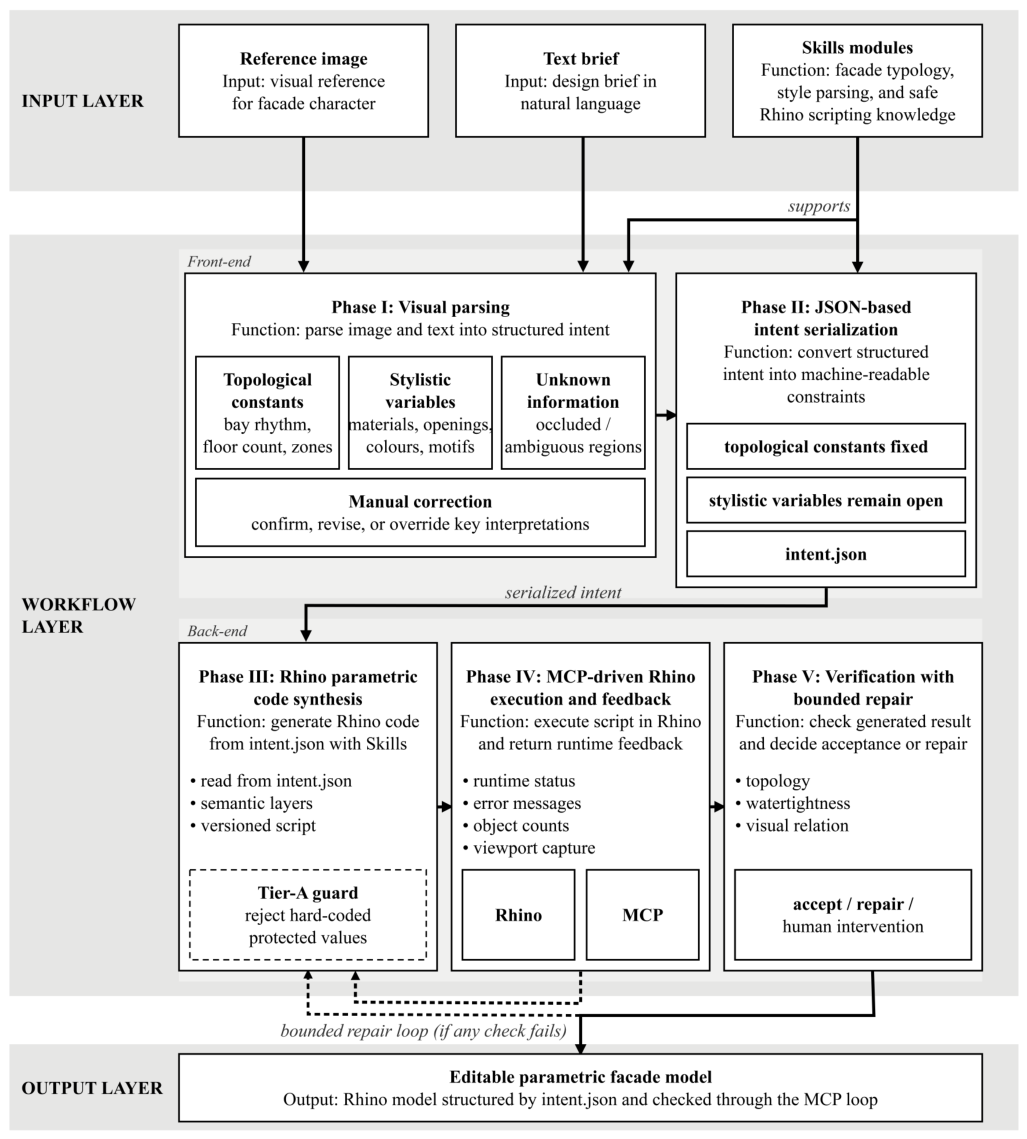
MLLMto3D is a closed-loop workflow for architectural facade generation. It takes a reference image and a natural-language brief as input and produces an editable parametric Rhino model through five phases. Phase I parses the image and brief into a structured description of facade organization. Phase II serializes the rigid parts into intent.json, fixing topological constants such as height, bay rhythm, and facade zones while leaving stylistic variables open. Phase III synthesizes parametric Rhino code with support from Skills modules that encode architectural typology and Rhino API safety patterns. Phase IV executes the code in Rhino through MCP and returns execution feedback. Phase V checks the result against topology, watertightness, and visual criteria; failure triggers a return to Phase III for bounded repair. The closed-loop architecture itself requires only a modeling environment that exposes a scriptable interface and can be connected through an MCP bridge. In this study, Rhino is the demonstration environment.
The three mechanisms map to the three research problems. MCP-driven execution and feedback addresses kernel instability by capturing runtime errors inside the CAD environment. JSON-based intent serialization addresses weak intent formalization by separating topological constants from stylistic variables before code generation. Skills modules address implicit domain knowledge by externalizing facade composition rules and safe Rhino scripting patterns. Table 1 maps these correspondences, including the ablation setting used to test each mechanism.
The five phases divide into two stages. Phases I–II construct structured intent before any code is written; a designer checkpoint after Phase II confirms or revises key topological decisions (see the User_Override record in Appendix A.2). Phases III–V form the generation-execution-repair loop. The final output is an editable parametric facade model constrained by intent.json and verified through the MCP-driven Rhino loop. Figure 1 summarizes the data flow.

3.2. Detailed Five-Phase Workflow

3.2.1. Phase I: Visual Parsing and Ambiguity Identification

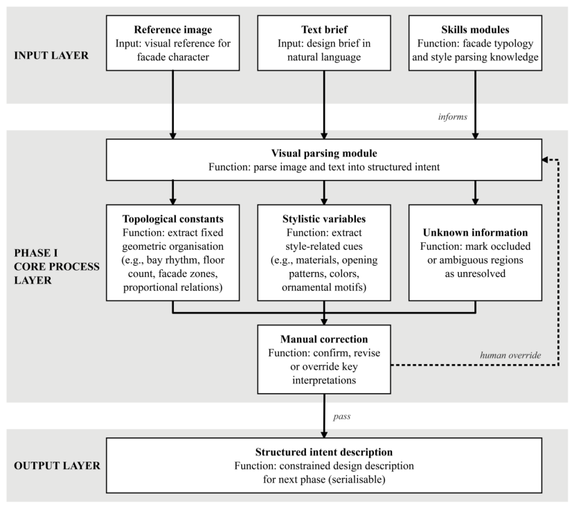
Phase I separates what must remain fixed from what may remain flexible. Architectural reference images contain structural information, stylistic cues, and occluded or ambiguous regions simultaneously. Before any code is generated, this phase parses the image and text brief into a structured intent description, preventing later stages from treating uncertain visual impressions as fixed geometry.
The description captures four types of information: topological constants (bay rhythm, floor count, facade zones, and proportional relations) that define the geometric organization to be preserved; stylistic variables (material families, opening patterns, color tendencies, and ornamental motifs) that guide facade expression without being treated as rigid dimensions; unknown regions (occluded or visually ambiguous areas) explicitly marked as unresolved rather than inferred; and manual corrections entered by the designer at a verification checkpoint to confirm, revise, or override key interpretations.
Skills modules guide this phase by encoding facade typology and style parsing knowledge. Their role is not to determine the final design, but to provide a stable vocabulary for reading the reference image (Figure 2).

3.2.2. Phase II: JSON-Based Intent Serialization

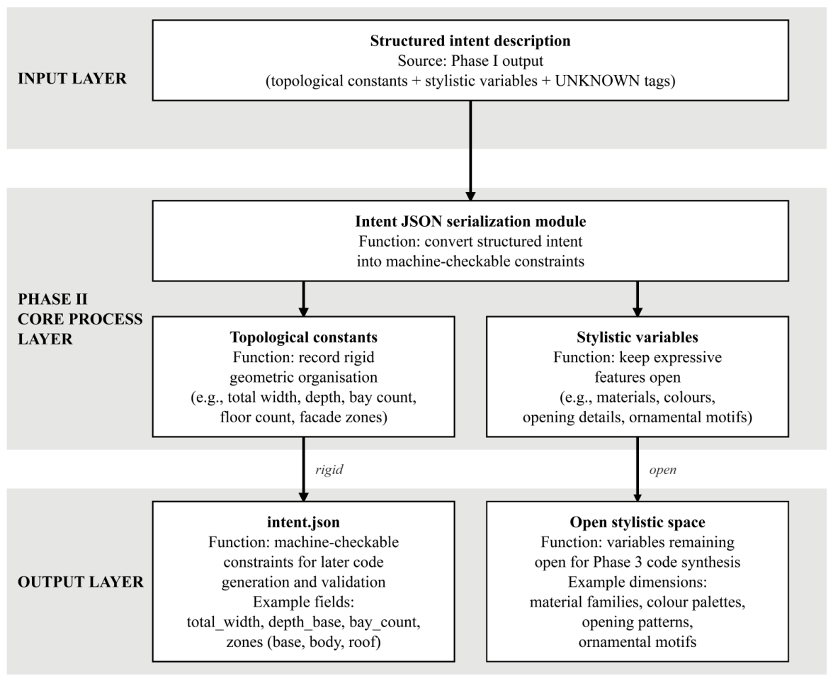
Phase II turns structural intent into machine-checkable constraints. The topological constants extracted and confirmed in Phase I are serialized into intent.json, making them explicit inputs for code generation and validation rather than prose that the model must re-infer at synthesis time.
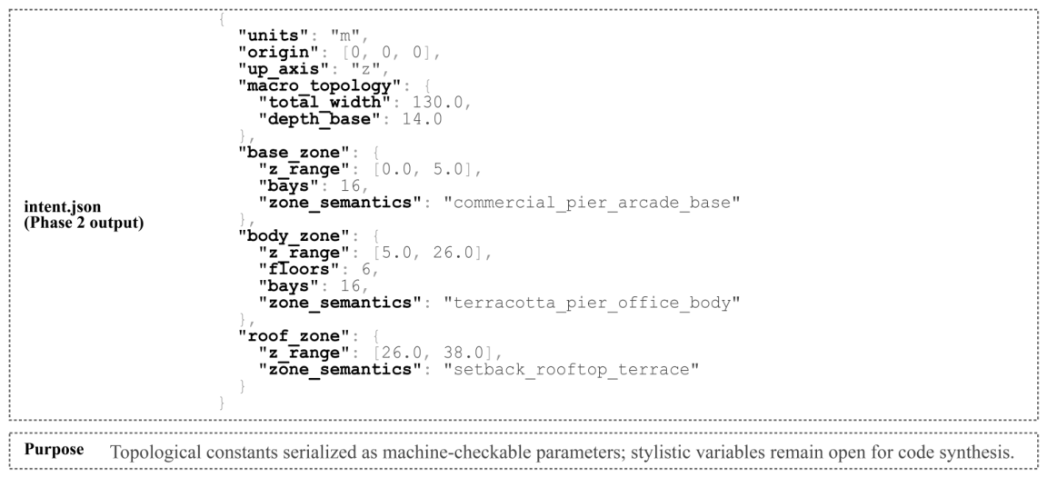
intent.json records only rigid geometric organization. Typical fields include overall width, depth, facade zones, floor counts, and bay count. Stylistic information—material choice, color tendency, opening details, ornamental profiles—is not fixed at this stage. Non-binding stylistic cues (e.g., zone-semantics tags) may accompany the JSON for downstream Skills-module use, but they are not checked by the Tier-A guard and may be revised during code synthesis. The complete intent.json for the experimental case is reproduced in Appendix A.3 and Figure A2. The intent.json schema is a single, general template bundled with the Skills modules. It specifies a tripartite base–body–roof organization parameterized by overall width, depth, bay count, and floor count. For each project, the language model fills in these values from the reference and the brief, so a new case instantiates the same template rather than authoring a new schema.
This separation makes the structured intent both an input to code generation and a benchmark for later verification (Figure 3).

3.2.3. Phase III: Rhino Pparametric Code Synthesis

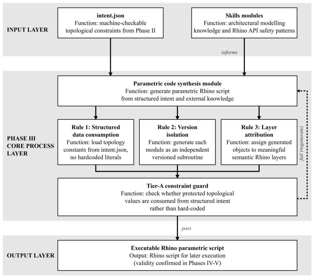
Phase III converts structured intent into executable parametric code. Code synthesis is constrained by two external inputs: intent.json and Skills modules that provide architectural modeling knowledge and Rhino API safety patterns.
Three rules govern synthesis. First, all topological constants must be read from intent.json rather than hard-coded as literals. Second, each iteration is organized as an independent model version, so that failed attempts can be inspected or rolled back. Third, generated objects are assigned to semantic layers reflecting their architectural roles or material categories.
The Skills modules are organized by concern. facade_morphology encodes typological knowledge drawn from established facade composition theory [42,43,44], including bay subdivision rules, tripartite zone proportioning, and inter-floor alignment logic. rhino_parametric_design wraps Rhino API calls with argument validation, return-value checks, and layer-naming conventions [45], functioning as a safety layer between the agent’s generated code and the CAD kernel. comprehensive_style_parsing translates the non-binding stylistic hints accompanying intent.json into parametric modeling instructions by mapping material registers, opening strategies, and ornament profiles to concrete geometric operations. Table 2 summarizes each module’s encapsulated knowledge and targeted risk.
Before transmission to Rhino, a Tier-A constraint guard checks whether the generated code has actually consumed the structured intent. If the script hard-codes protected topological values, it is rejected and returned to code synthesis. This pre-execution audit catches cases where the agent appears to follow the JSON constraint while regenerating dimensions from prose or memory (Figure 4).

3.2.4. Phase IV: MCP-Driven Rhino Execution and Feedback

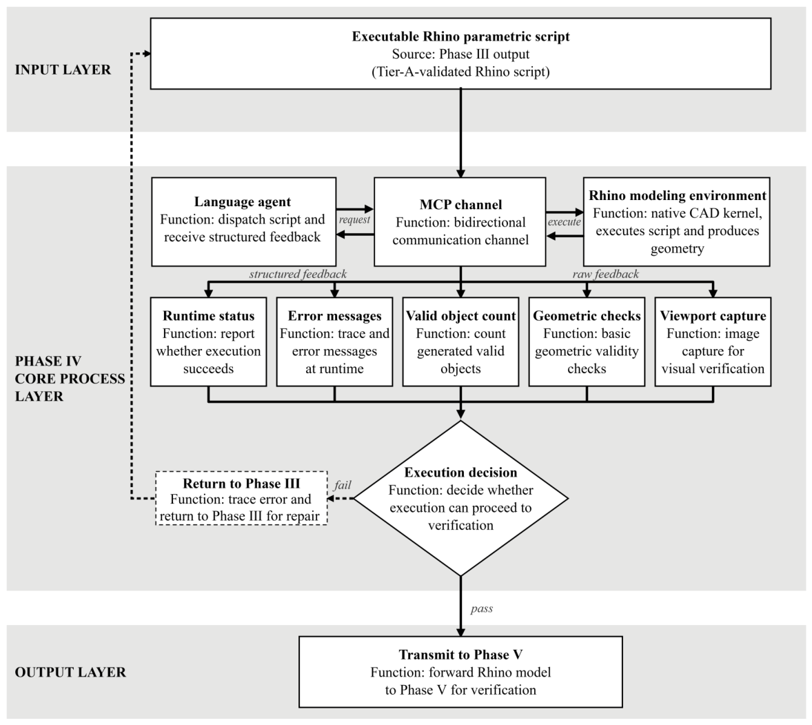
Phase IV turns Rhino execution into a feedback source. The generated script is executed in Rhino through MCP, and the execution result is returned to the language agent as structured feedback [46].
The returned feedback includes runtime status, error messages, valid object counts, basic geometric checks, and viewport captures. These signals allow the workflow to distinguish between a script that merely exists and a model that has actually been built in the CAD environment—API errors, failed operations, empty outputs, or malformed geometry are detected before the result is accepted.
If execution succeeds, the model and its feedback are passed to Phase V. If it fails, the error trace is returned through MCP and used to guide the next code synthesis attempt (Figure 5).

3.2.5. Phase V: Verification with Bounded Repair

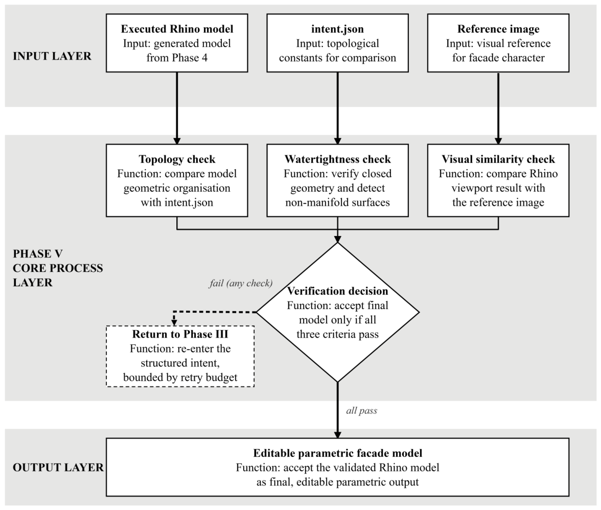
Phase V decides whether the executed model can be accepted or must be repaired. Verification combines three criteria: topology, which checks whether the generated model follows the topological constants in intent.json (overall dimensions, facade zones, floor organization); watertightness, which checks whether the geometry forms valid closed objects rather than fragmented or malformed surfaces; visual relation, which presents the Rhino viewport side by side with the reference image for inspection rather than scoring it against a threshold.
If any criterion fails, the failure information is returned to code synthesis, where the language agent revises the script under the same structured intent. Repeated failure is treated as a signal for human intervention rather than unlimited automatic repair (Figure 6).

4. Experimental Validation

4.1. Experimental Design and Site Selection

The experiment is a feasibility test. It asks whether MLLMto3D can read a heritage facade, extract structured modeling constraints from it, and produce an editable Rhino model for a new building on an adjacent plot. The evaluation checks constraint preservation and geometric validity; it does not assess architectural design quality.
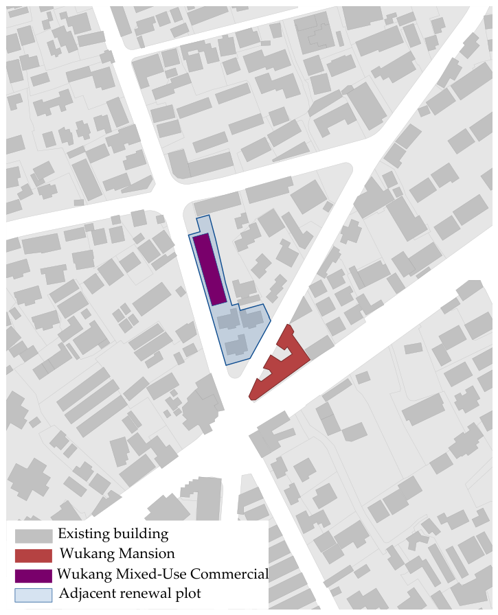
The case study site is situated in Shanghai’s Hengfu Historic District, adjacent to the renowned heritage building, Wukang Mansion. Its bay rhythm, vertical organization, material register, and corner condition supply the geometric and compositional constraints that Phase I must extract. The new building is a contemporary commercial block with a target envelope of approximately 130 m in façade width and 38 m in height, whose façade should relate to the heritage neighbor without copying it. Whether the generated Rhino model holds together as valid geometry, whether it matches the intent.json extracted from the reference, and whether the visual relation is recognizable: these are the questions the experiment answers. The full site brief, including regulatory constraints and design direction, is in Appendix A.1. Figure 7 situates the case site by showing the five-way street junction, the existing Wukang Mansion, and the adjacent renewal plot designated for the new building.
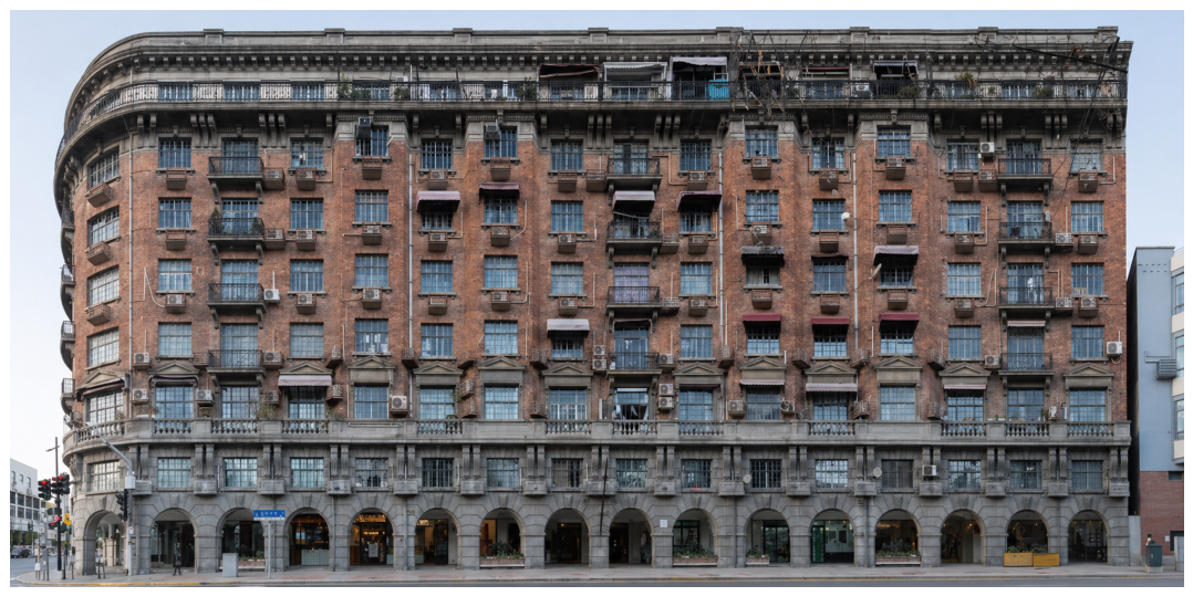
The two buildings in the case can be specified as follows. The heritage reference, the Wukang Mansion (originally the Normandie Apartments, completed in 1924), is an eight-storey exterior-corridor apartment building approximately 30 m high, with a footprint of about 1580 m2 and a gross floor area of about 9275 m2, built in reinforced concrete; its street facade follows a three-part vertical composition (a washed-stone lower facade, a clay-brick middle, and an imitation-stone cornice) that the workflow adopts as the compositional source. The generated subject is a new building whose envelope the workflow produces: beyond the width and height noted above, its base depth is about 14 m, it is organized in a 16-bay rhythm, and it follows a tripartite vertical zoning, namely a commercial arcade base (0–5 m), a six-storey office body (5–26 m), and a setback rooftop terrace zone (26–38 m). Because the workflow operates at the level of facade and envelope generation, the structural system and structural materials of the new building lie outside its scope and are not part of the generated model. The full design brief is reproduced in Appendix A.1.

4.2. Experimental Process

The experiment follows the five-phase workflow defined in the methodology. The language agent is Alibaba Cloud’s Qwen-VL-Max-Latest, accessed through DashScope’s OpenAI-compatible endpoint, and the same model drives all five phases. The input is a reference photograph of the Wukang Mansion and a text brief for the new building on the adjacent plot. The brief asks the workflow to preserve the reference’s bay rhythm and tripartite vertical organization while expressing the new building in a contemporary commercial form. The framework is model-agnostic in design; the results here are tied to this specific model and should not be extrapolated without further evaluation. The reference photograph and full brief are in Appendix A.1.
Phases I and II convert the reference into structured intent. Visual parsing extracts bay rhythm, vertical zones, material register, and uncertainty tags from the image. Unresolved fields are routed through a designer checkpoint. The confirmed topological constants are serialized into intent.json; stylistic information stays outside the JSON and is left for code synthesis. The Phase I grammar and resulting intent.json are reproduced in Appendix A.2 and Appendix A.3.
Phases III and IV generate and execute the Rhino model. The agent synthesizes Rhino code under intent.json constraints and Skills modules. The Tier-A guard checks that protected values are read from the JSON rather than hard-coded. The accepted script is executed in Rhino through MCP, which returns object validity and geometric status as feedback. The script header and top-level orchestration appear in Appendix A.4 (full 909-line script in Supplementary Materials); Phase IV evaluator output is in Appendix A.5.
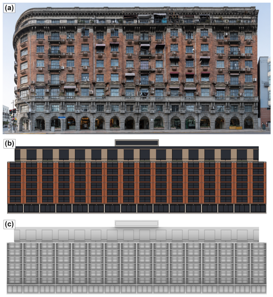
Phase V verifies the result against topology, watertightness, and visual relation criteria. The workflow completed without entering the bounded repair loop. Per-criterion outcomes are summarized in Table 3; the full verification report is in Appendix A.6; the viewport comparison is in Figure 8.

4.3. Experimental Results

4.3.1. Evaluation Framework

The evaluation asks whether the workflow produces a model that is constrained, executable, and geometrically valid, while also presenting its visual relation to the reference for inspection. The criteria follow the verification logic defined in Phase V and correspond to the three technical challenges identified above. Three pass-fail indicators are used—constraint compliance, topology consistency, and watertightness—together with a fourth inspection item, visual relation to the reference, which is presented rather than scored against a threshold. Together, they evaluate whether the generated facade is not only plausible as an image, but also usable as an editable Rhino model.
Constraint compliance checks whether the generated code follows the structured intent. Before Rhino execution, the system verifies whether protected topological constants are read from intent.json rather than directly hard-coded into the script. This criterion evaluates the effectiveness of JSON-based intent serialization. A pass means that the model generation remains tied to the structured intent rather than relying on the language agent’s implicit reconstruction of dimensions.
Topology consistency checks whether the built model preserves the intended facade structure. The generated geometry is compared with the topological constants recorded in intent.json, including overall dimensions and vertical zone boundaries. Parameters that cannot be reliably inferred from geometric measurement are excluded from the denominator rather than treated as failures. The topology score is reported as the ratio between passed and measurable parameters.
Watertightness checks whether the generated geometry forms valid closed objects. A facade model that passes visual inspection may still contain fragmented surfaces, open edges, or malformed geometry. This criterion therefore evaluates whether the output can be treated as a valid CAD model rather than only a visual approximation. In the experiment, passing watertightness means that the generated objects contain no detected open-edge or non-manifold problems.
The visual relation to the reference is presented for inspection rather than scored. The Rhino viewport result and the reference photograph are placed side by side so that contextual relation can be inspected directly. The raw CLIP descriptor is reported for transparency, but no threshold is adopted, and the value is not used as a pass-fail criterion. Since CLIP is not validated as a measure of architectural composition or stylistic register, treating it as a binary judge would overreach what the score can support. The limitations of CLIP-based similarity are taken up in the discussion.
Repair convergence records how many iterations are required before all criteria pass. A run that completes without entering the repair loop indicates that the initial code synthesis, Rhino execution, and verification all proceeded without triggering repair. If any criterion fails, the workflow returns to code synthesis under the same structured intent. Repeated failure is treated as a signal for human intervention rather than unlimited automatic repair. Because the experiment uses a single experimental case, the results are reported as a case-based audit trail rather than a statistical claim.

4.3.2. Primary Case Result

The experimental case reached acceptance without entering the Phase V bounded repair loop. The generated script, after one Phase-III Tier-A regeneration triggered by hard-coded literals in the first synthesis attempt (full attempt history in Appendix A.8), passed the pre-execution constraint check, and the Rhino output satisfied the topology and watertightness criteria. The “no repair iteration” claim therefore refers specifically to Phase V geometric repair: pre-execution synthesis regeneration triggered by the Tier-A guard is disclosed in the attempt trace and does not consume the bounded-repair budget. Table 3 summarizes the evaluation results for the case; the full verification report is reproduced in Appendix A.6, the CLIP-descriptor reporting policy is documented in Appendix A.7, and the on-disk attempt history is reproduced in Appendix A.8. In this trace, the interval from the Tier-A rejection to the first fully accepted run was approximately 117 s of wall-clock time, covering script regeneration, Rhino execution through MCP, and Phase V verification.
The new building’s generated facade preserves the structural intent of the reference while expressing a distinct contemporary identity. The output retains the 16-bay rhythm, tripartite vertical organization, and material lineage extracted from the Wukang reference. At the same time, the new building expresses these features through a contemporary commercial facade, including a more transparent ground level, larger window modules, and a setback rooftop terrace. The result is therefore not a copy of the reference, but a new building facade that maintains a controlled contextual relation to the Wukang Mansion while remaining editable in Rhino.
The side-by-side comparison is presented for inspection rather than as a scored judgment. The new building is required to maintain a visible contextual link to the heritage reference while remaining a new design rather than a reproduction. The reference photograph and the Rhino viewport result are placed side by side so that this relation can be inspected directly; the raw CLIP descriptor is reported alongside as a numerical record of pixel-level similarity, without any threshold-based pass-fail claim.
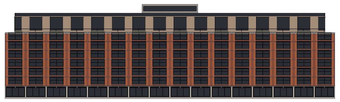
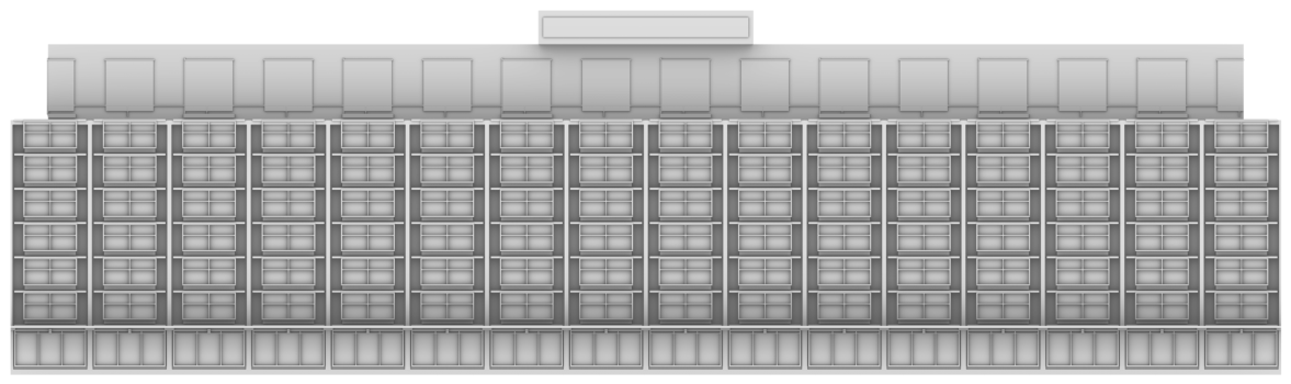
Across all three panels the generated facade preserves the 16-bay rhythm of the heritage reference and reorganizes it into a tripartite vertical composition—a transparent retail base, a terracotta-pier body with bronze mullions, and a setback rooftop terrace.
Architecturally, the result should be read as a translation of compositional order rather than a reproduction of visual style. The 16-bay rhythm is retained as a regulating grid, but the individual bay expression is enlarged and simplified for a contemporary commercial program. The tripartite organization is also preserved, yet its components are reinterpreted: the base becomes a more transparent retail frontage, the middle zone becomes a regular terracotta-and-glass office body, and the upper zone becomes a setback rooftop terrace. In this sense, the generated model establishes continuity with the Wukang reference through rhythm and vertical hierarchy, while allowing material expression and facade articulation to diverge from the historic source.

4.4. Diagnostic Ablation

The ablation is diagnostic rather than performance-comparative. Using the same experimental case, the workflow was re-run under three configurations. Each configuration removed one mechanism while keeping the remaining workflow unchanged: MCP-driven Rhino execution and feedback, JSON-based intent serialization, and Skills modules. The aim is not to compare success rates, but to locate where the workflow first fails when a mechanism is missing. The corresponding on-disk attempt history (including the Tier-A guard activations) is reproduced in Appendix A.8.
A1 removes the closed-loop repair mechanism. The generated script is executed once, but verification feedback is not used to trigger a bounded repair loop. This setting tests whether execution feedback and repair are necessary when generated code fails in the CAD environment.
A2 removes JSON-based intent serialization. Instead of receiving machine-readable topological constants, the language agent must infer key dimensions from prose descriptions. This setting tests whether structured intent is necessary for preserving geometric constraints during code synthesis.
A3 removes the Skills modules. The language agent no longer receives externalized facade-typology knowledge or Rhino API safety patterns. This setting tests whether the Skills modules are necessary for reducing semantic misreadings and API hallucinations (Table 4).
The three ablations locate different failure stages. Removing MCP exposes runtime failure, removing JSON-based intent serialization exposes pre-execution constraint drift, and removing Skills modules exposes API-surface hallucination. This supports the division of labor among the three mechanisms, while remaining diagnostic evidence from a single case rather than a statistical comparison. The N = 10 sampling distribution (Table A4 in Appendix A.10) confirms that the per-ablation failure-stage signatures observed in the pilot run are not artifacts of a single execution trace: A1 still splits between Tier-A and Rhino runtime failures, A2 still concentrates in pre-execution constraint drift, and A3 still fails entirely before reaching valid Rhino execution.

4.5. Experimental Analysis

The evaluation establishes a limited form of validity. The Tier-A guard, topology consistency check, and watertightness check show whether the generated model remains tied to the structured intent file and whether the resulting Rhino geometry is valid at the CAD level. Passing these checks means that the script reads protected parameters from intent.json, the measurable geometric relations remain within tolerance, and the output consists of closed CAD objects. This supports a claim about constrained model production, not about architectural design quality. These checks correspond to the lower-level preconditions of architectural modeling rather than to architectural judgment itself. A facade cannot be meaningfully discussed as a design artifact if it is not executable, editable, or geometrically valid; however, passing these checks only opens the model to architectural interpretation, rather than completing that interpretation.
This distinction is important for interpreting the result. A model that passes the three checks may still require architectural judgment in relation to proportion, contextual fit, constructional logic, regulation, and use. These aspects are not captured by the operational checks used here. The raw CLIP descriptor is treated in the same limited way. It is reported for transparency, not as a measure of architectural composition or stylistic quality. The side-by-side visual comparison is included to make the relation to the reference inspectable rather than to convert contextual fit into a single score.
The ablation traces indicate where the workflow becomes unstable when specific mechanisms are removed. In the No-MCP setting, failure appears during Rhino execution, after the generated script passes the pre-execution guard. In the No-JSON setting, failure appears before execution, when protected topological values re-enter the generated script as hard-coded literals. In the No-Skills setting, failure appears at the API surface, where the agent produces a Rhino function call that is not available in the target API. These locations correspond to different responsibilities in the workflow: MCP carries runtime feedback, JSON-based intent serialization constrains the transfer from design description to executable code, and Skills modules provide reusable knowledge about facade organization and Rhino scripting.
Beyond the single execution trace, an N = 10 sampling study was carried out for the three ablations, on the same experimental case and under fixed structured inputs, varying only the language model’s stochastic decoding. The aim is to check that the per-ablation failure-stage signatures above are not single-trace coincidences. Across 10 runs per ablation, A1 splits between Tier-A guard rejections and Rhino runtime errors, A2 concentrates in Tier-A guard rejections (with one run that incidentally produced executable geometry), and A3 fails universally before reaching valid Rhino execution. Per-rep traces, generated scripts, and evaluator outputs are archived in the supplementary repository; the per-rep summary is given in Appendix A.10. This study is a robustness check on the ablation argument, not a statistical evaluation of full-pipeline success rate, which remains a single-case feasibility claim.
The experimental case should therefore be read as feasibility evidence. It demonstrates that the workflow can complete one controlled design task under specified input and modeling conditions. It does not test generalization across facade types, urban settings, or design briefs. These broader issues are taken up in the discussion.

5. Discussion

5.1. Positioning Within Existing Design Workflows

MLLMto3D sits between parametric modeling and AI generation. Conventional parametric tools such as Rhino and Grasshopper provide precise geometric control and editable models, but their modeling logic usually has to be defined manually. Image-generation tools support rapid visual exploration, but their outputs remain outside the CAD modeling process. LLM-to-CAD and LLM-to-3D systems reduce the scripting burden, yet many of them still treat generated code as the endpoint of the workflow. MLLMto3D occupies a different position: it uses multimodal input to construct structured intent, generates Rhino code from that intent, and uses Rhino execution feedback to check or repair the result.
The difference lies in where feedback enters the process. In manual parametric modeling, feedback comes mainly from the designer’s inspection and adjustment. In image-generation workflows, feedback is usually visual and external to the modeling environment. In open-loop LLM-to-CAD workflows, feedback often appears only after the user tests or debugs the generated script. In MLLMto3D, feedback is moved into the workflow itself. Rhino is not only the software that receives the generated script; it is also the environment that returns execution status, object validity, and geometric information.
This changes the role of the designer, but does not remove it. The designer no longer has to define every modeling operation by hand, but still provides the reference, brief, and judgment needed to guide the process. The workflow can structure intent and produce an editable Rhino model, yet architectural decisions about proportion, use, context, and design quality remain outside the automated checks. In this sense, MLLMto3D is best understood as an assisted modeling workflow rather than an autonomous design system.

5.2. Implications for Architectural Design

The workflow makes design intent more explicit. In many AI-assisted design processes, the relation between the prompt, the generated image, and the later CAD model remains loose. MLLMto3D changes this relation by inserting a structured intent layer between multimodal input and model generation. In the experimental case, this layer decouples the reference building’s bay rhythm, vertical organization, and dimensional constraints from more open-ended stylistic decisions. The design reference is therefore not used only as visual inspiration; part of it is translated into explicit modeling constraints.
This changes how contextual reference can be used in architectural design. The Wukang Mansion is not treated as a formal template to be copied, but as a source of transferable compositional relations. In the experiment, bay rhythm and vertical hierarchy are fixed as topological constraints, while material treatment, opening size, and commercial frontage remain variable. This separation reflects a common design problem in heritage-adjacent urban renewal: how to maintain continuity with an existing architectural fabric without reproducing its historical appearance. MLLMto3D does not solve this problem as a design judgment, but it provides a way to make the chosen relation explicit and operable in a CAD model.
The design process becomes more inspectable. Because the workflow stores intent in intent.json, generates code under this constraint, and checks the output in Rhino, the design process leaves an audit trail. A designer can inspect which parameters were fixed, which features were left open, and where errors occurred during execution. This does not replace architectural judgment, but it can make AI-assisted modeling easier to review, revise, and discuss. For early-stage design, this kind of traceability may be more useful than a visually convincing but non-editable image.
The contribution is therefore procedural rather than stylistic. The main value of MLLMto3D is not that it generates one particular facade language. Its value lies in testing how multimodal reference, structured intent, parametric code, and CAD feedback can be connected in one design workflow. The present experiment demonstrates this at the facade level, where compositional order and model validity can be checked within a bounded task. Extending the same logic to massing, spatial organization, or urban-scale design would require additional representations and evaluation methods.

5.3. Limitations and Future Extensions

The experiment evaluation is based on one experimental design case, one execution trace, and a Rhino-based implementation, so it does not provide statistical evidence across building types, design briefs, or modeling environments. The current evaluation also remains limited to model production. It checks whether the generated script follows intent.json, whether the Rhino output preserves measurable topology, and whether the geometry forms closed CAD objects, but it does not assess proportion, contextual appropriateness, spatial use, constructional logic, or regulatory compliance through expert review. The workflow also depends on the combined use of MCP, JSON-based intent constraints, and Skills modules; how it degrades when one component is unavailable has not yet been tested. The iterative cycle is also resource-intensive. Each closed-loop attempt incurs one language-model inference for code synthesis and one multimodal evaluation of execution feedback, so the cost is approximately additive in the number of attempts. The accepted run reported above took about 117 s on the single-facade case (1387 closed polysurfaces; Section 4.3.2); because it triggered no Phase V repair, this is a no-repair lower bound, and each further repair iteration adds roughly one more synthesis–execution–verification cycle. How this cost profile behaves on complex, large-scale objects, where both scene size and the expected number of repairs grow, remains an open task for evaluation. Future work should therefore extend the evidence base through multi-case experiments, direct LLM-to-CAD baselines, repeated runs, and structured architectural expert evaluation. It should also expand the representation layer beyond regular facade topology, including irregular or non-orthogonal facades, multi-view references, occlusion handling, confidence reporting in visual parsing, and links from Rhino geometry to BIM or IFC entities. Because the single intent template covers regular, vertically zoned facades, reaching these less regular organizations requires extending the schema, not redesigning the workflow; semi-automated schema generation from annotated references is one route to that extension. The workflow also generalizes beyond Rhino. Porting it to platforms such as Revit, Blender, or AutoCAD, which likewise expose scriptable interfaces and MCP bridges, requires retargeting the code-synthesis layer and the Skills modules to the host API, while the intent schema is reused unchanged and the verification criteria are re-expressed in the host platform’s validity model (for example, manifold-mesh checks in Blender or element/parameter validity in Revit). Mapping the generated geometry to the IFC entities noted above is a deeper extension. Deepening the workflow from facade and envelope generation toward the structural system and material specification of the building, which it deliberately leaves out of scope at present (Section 4.1), is a further direction for future work. These extensions would allow the workflow to move from a facade-level feasibility study toward broader architectural design tasks, while keeping model validity and architectural judgment analytically separate.

6. Conclusions

This paper presents MLLMto3D, a closed-loop framework for architectural 3D generation. It introduces MCP to enable iterative generation–execution–feedback–repair cycles, JSON-based intent serialization, and reusable Skills modules. MCP allows the language agent to connect with Rhino and establish a loop across generation, execution, feedback, and repair, turning one-shot script output into a verifiable modeling process. JSON-based intent serialization further encodes architectural rules from images and text into machine-readable intent, providing stable constraints for code synthesis and model verification. Skills modules externalize facade typology knowledge and safe Rhino scripting patterns as reusable resources, intended to reduce design-intent deviation and API hallucination. Together, these mechanisms form an extensible interface among multimodal AI agents, professional modeling software, and architectural knowledge bases. This interface stays open in two respects: the intent schema is one general template rather than a per-case specification, and the closed loop needs only a scriptable modeling environment reachable through MCP. Both the schema and the host platform can therefore be extended without redesigning the framework’s core. As a feasibility study, this paper outlines such an interface; broader application across building types, modeling platforms, and urban renewal contexts is identified as a direction for subsequent validation.

Supplementary Materials

The following supporting information can be downloaded at: https://www.mdpi.com/article/10.3390/buildings16122437/s1, the complete reproducibility package for this study, comprising (i) the experimental case (design brief, reference image, the Phase I grammar, intent.json, the full 909-line procedural generator, the Tier-A guard, topology, and CLIP evaluator scripts, and the Phase V verification report) and (ii) the N = 10 diagnostic-ablation grid (the batch-run and aggregation scripts, the pinned environment record, and the per-repetition traces—prompts, model responses, generated scripts, evaluator outputs, viewport captures, and input SHA-256 hashes—together with results.csv and results_summary.csv).

Author Contributions

Conceptualization, D.Y. and B.H.; methodology, B.H.; software, B.H.; validation, B.H. and X.Z.; formal analysis, B.H.; investigation, B.H.; resources, D.Y.; data curation, B.H.; writing—original draft preparation, B.H.; writing—review and editing, D.Y., B.H. and X.Z.; visualization, B.H.; supervision, D.Y.; project administration, D.Y. All authors have read and agreed to the published version of the manuscript.

Funding

The research, writing and publication are solely funded by National Key R&D Program of China (2023YFC3805503).

Institutional Review Board Statement

Not applicable.

Informed Consent Statement

Not applicable.

Data Availability Statement

The data, evaluator scripts, the case’s intent JSON, generator scripts, viewport screenshots, and the aggregated results.csv that support the findings of this study are not yet publicly archived but are available from the corresponding author on reasonable request. Every numeric value reported in the experimental validation and the diagnostic ablation traces back to a row in the project’s experiments/results.csv. The full pilot run is reproduced by experiments/shared/retry_wrapper.py (single-command form documented in Appendix A.9), and the N = 10 ablation grid is reproduced by experiments/batch_run.py –config <A1_no_mcp|A2_no_json|A3_no_skills> –reps 10 followed by experiments/aggregate_results.py (also documented in Appendix A.9). Both entry points require a running Rhino 8 instance with the MCP bridge active. On acceptance of the manuscript, the codebase will be released under an open-source license at a public Git repository, and this statement will be updated with the canonical URL. For provenance, the heritage reference is referred to throughout this manuscript as Wukang Mansion; the raw prompts, responses, and generator scripts archived in the code release retain the legacy case identifier from the time of execution, which denotes the same building.

Acknowledgments

The authors thank the College of Architecture and Urban Planning, Tongji University, for institutional support.

Conflicts of Interest

The authors declare no conflicts of interest.

Abbreviations

The following abbreviations are used in this manuscript:
AIArtificial Intelligence
APIApplication Programming Interface
ASTAbstract Syntax Tree
BIMBuilding Information Modeling
CADComputer-Aided Design
CLIPContrastive Language–Image Pretraining
IFCIndustry Foundation Classes
JSONJavaScript Object Notation
LLMLarge Language Model
MCPModel Context Protocol

Appendix A. Experimental Case Execution Trace

This appendix records the actual artifacts produced at each phase of the experimental case run. The artifacts are presented in their raw form—image, JSON, Python script, and console log—so that the execution is publicly reproducible: a reader who configures the same Skills modules and uses the intent.json reproduced below can replay the workflow against the same Rhino API surface and verify the reported result. All Python artifacts reproduced in this paper were produced under Python 3.12.7 (the CLIP descriptor uses PyTorch 2.5.1 and Transformers 5.1.0), and the parametric model is built in Rhino 8.

Appendix A.1. Input—Reference Photograph and Design Brief

Figure A1. Reference photograph of the Wukang Mansion used as workflow input. (Source: photographed by authors).
Buildings 16 02437 g0a1
The accompanying design brief is reproduced verbatim from the case folder; site-regulation fields originally written in mixed Chinese–English are translated into English here, and the bilingual original is preserved in the Supplementary Materials.
# Design Brief: Wukang_MixedUse_Commercial
 
## 1. Case Identifier
- Building Name      : Wukang_MixedUse_Commercial
- Reference Building : Wukang Mansion, Shanghai
- Reference Image    : reference/Wukang_reference.png
- Site Location      : Shanghai, Xuhui District, adjacent renewal plot near Wukang Mansion
- Brief Date         : 27 April 2026
 
 
## 2. Site Constraint
- Plot Position      : Adjacent renewal plot within the immediate visual context of Wukang Mansion and the surrounding heritage street block
- Height Limit       : 38 m, aligned with Wukang ridge, subordinate to heritage skyline
- Setback Requirement: 6 m street, 4 m side, 3 m neighboring lot
- Coverage Ratio     : <= 0.55, ground-level public access required
- Heritage Buffer    : Visually compatible with Wukang Mansion in scale, facade rhythm, and material atmosphere within 30 m coordination distance; direct imitation prohibited
- Other Regulations  : Heritage protection core sector; facade material subject to planning review; preserve key sightlines toward Wukang Mansion; no oversized illuminated signage
 
## 3. Design Direction
- Translation Mode   : Translation (modernist transposition: preserve topological skeleton, replace stylistic vocabulary)
 
- Stylistic Anchors to Preserve  :
   - Base-body-top facade hierarchy
   - Clear vertical bay rhythm and continuous street-wall relationship
   - Strong street-corner urban presence
   - Human-scaled podium expression
   - Masonry-like facade texture and visual weight
   - Active mixed-use ground floor (retail + lobby + restaurant frontage)
 
- Stylistic Anchors to Translate :
   - Historic masonry -> contemporary piers + infill panels
   - Continuous arcade -> transparent retail frontage + canopies + sheltered pedestrian edge
   - Corner emphasis -> commercial landmark corner / softened rounded articulation
   - Repetitive residential window rhythm -> larger commercial / office window modules
   - Tripartite hierarchy -> podium-commercial base + repetitive middle zone + setback rooftop terrace
   - Decorative reliefs -> subtle shadow grooves and facade depth changes
 
- Stylistic Anchors to Drop      :
   - Literal historic ornament replication
   - Residential balcony clutter
   - Domestic-scale facade elements
   - Direct copying of Wukang’s signature wedge-corner form
   - Excessively enclosed ground-floor wall
   - Oversized roof billboards / full-facade LED screens
 
- Material Strategy  : Same family, different material. Terracotta-toned cladding + stone-like base + dark bronze metal framing + low-reflectivity glazing; contemporary commercial identity, no historic literal copying
- Color Strategy     : Palette resonance. Warm brick-red, beige-gray, dark bronze / charcoal metal, low-reflectivity glass; no saturated branding colors on the main facade
 
## 4. Output Goal
- Geometric Output  : Rhino .3dm mixed-use commercial block facade model, semantic layer namespace WUKANG_COMM::*
- Verification Pass : Topology and watertightness criteria PASS at Phase 5; CLIP cosine similarity is recorded as a descriptor only, with no pass-fail threshold applied
- Failure Tolerance : Retry <= 2; out-of-budget runs archived as [Failure Case]
- Downstream Use    : Paper experimental case -- context-sensitive commercial complex generation under heritage constraint
 
## 5. Notes for Phase 1
- Reference image is the SW elevation of Wukang Mansion; foreground plane trees occlude bays 1--3 floors 1--2 (~20%)
- Curved corner tower ~60% visible; occluded portion -> UNKNOWN tag
- Floor 1--2 storefront signage, AC units, temporary commercial accretions are not core stylistic anchors
- RGB sampling concentrated in floors 4--6 unobstructed mid-band
- Generated result is a NEW commercial complex adjacent to Wukang, not a heritage replica

Appendix A.2. Phase I Output—Visual Parsing Grammar

The Phase I grammar file Wukang_MixedUse_Commercial_grammar.md is reproduced verbatim below. It captures the source heritage building in four parts: topological constants, procedural style anchors and material palette, uncertainty tags, and the user-override record entered at the Phase I verification checkpoint. The translation rules in design_brief.md (the Preserve/Translate/Drop section) are applied in Phase III and do not modify Part 1.
# Grammar: Wukang_MixedUse_Commercial
 
> Phase 1 visual parsing of the reference image (Wukang Mansion, SW long flank).
 
# Part 1: Topological Constants
 
| Field            | Value                                                                                |
| ---------------- | ------------------------------------------------------------------------------------ |
| total_width      | 130.0 m                                                                              |
| depth_base       | UNKNOWN -- single elevation view, not derivable                                       |
| bays             | 14                                                                                   |
| base_zone        | z_range [0.0, 5.0] m, floors 1, semantics arched_arcade_base                         |
| body_zone        | z_range [5.0, 26.0] m, floors 6, bays 14, semantics punched_brick_residential_body   |
| roof_zone        | z_range [26.0, 38.0] m, semantics recessed_attic_plus_terrace                        |
| symmetry_axis    | asymmetric -- rounded prow tower at bay 1 (east end); flat terminus at bay 14 (west)  |
| facade_edges_x   | [0.0, 130.0]                                                                         |
| total_height     | 38.0 m                                                                               |
 
Provenance notes (do not affect the values above):
 
- ‘total_width = 130.0‘ is consistent with the brief’s implicit anchor (38 m height limit aligned to Wukang ridge -> corresponding plan length per heritage record) and the proportional reading of the elevation photograph (total_width : total_height ~= 3.4 : 1, typical of long-flank Shanghai apartment blocks of this period).
- ‘bays = 14‘ is the count of distinguishable arcade arches in the photograph (~3 arches on the curved prow + ~10 regular arches on the straight flank + ~1 arch at the right terminus). The right-end count carries residual uncertainty (see Part 3).
- Zone splits derive from the visible stringcourse positions: a strong horizontal break at the top of the arcade (~5 m); a secondary cornice break above floor 7 (~26 m); the recessed attic + roof equipment cluster occupies the upper 12 m to the parapet ridge.
 
# Part 2: Procedural Style Anchors and Material Palette
 
## 2.1 Aperture primitives
 
- **Continuous semicircular arcade** at floor 1, spanning all bays [1..14]. Each arch is a ‘semicircular_arch‘ with rise/span ~= 0.5. On the curved prow (bays [1..3]) arches inscribe a curved wall; on the straight flank (bays [4..14]) spans are uniform.
- **Bel étage rectangular windows** at floor 2, bays [1..14]. Apparent height/width ~= 1.6 : 1, larger than upper-floor windows. Paired with continuous balcony rail.
- **Punched rectangular windows** at floors [3..7], bays [1..14]. Standard residential punched windows, height/width ~= 1.4 : 1, vertically aligned with bel étage windows below.
- **Recessed attic windows** at floor 8 (within roof_zone), bays [1..14]. Lower proportion (height/width ~= 1.0 : 1), set in a recessed wall plane offset inward from the body face.
 
## 2.2 Additive features
 
- **Rounded prow tower** at bays [1..3]: curved wall bulging ~2--3 m outward; full-height curved volume; primary "corner emphasis" Preserve-class anchor (translated to "softened rounded articulation" in Phase 3).
- **Continuous arched arcade** at floor 1, bays [1..14]: covered colonnade with semicircular arches on a stone base.
- **Stringcourse / belt course** at z ~= 5.0 m, bays [1..14]: continuous horizontal stone band ~300 mm thick.
- **Continuous balcony band** at floor 2, bays [1..14]: continuous balustrade projecting ~300 mm from the wall plane.
- **Juliette balconettes** at floors [3..7], bays [1..14]: small iron-rail balconettes attached to each punched window.
- **Capping cornice** at z ~= 26.0 m, bays [1..14]: horizontal stone band separating body_zone from roof_zone.
- **Recessed attic plane** at floor 8 (z [26.0, 29.0]): wall set back ~600 mm from body face, capped by a thin coping.
- **Parapet + roof terrace** at z [29.0, 38.0]: open terrace with low parapet/balustrade; rooftop equipment in the photograph is explicitly excluded from the grammar (per note 3 of the design brief).
 
## 2.3 Rhythm grammar
 
- Macro composition: prow + flank -- ‘[curved_prow_volume at bays [1..3]] + [repetitive_flank at bays [4..14]]‘.
- Arcade: continuous repetition ‘arch at bays [1..14] of floors [26]‘.
- Bel étage windows: ‘bel_etage_window at bays [1..14] of floors [31]‘.
- Body windows: ‘punched_window at bays [1..14] of floors [3..7]‘.
- Balconettes: ‘juliette_balconette at bays [1..14] of floors [3..7]‘ (one per window).
- Attic windows: ‘attic_window at bays [1..14] of floors [29]‘.
 
## 2.4 Material palette (apparent RGB, not ground-truth)
 
Sampled from mid-tone, mid-floor regions of the photograph (avoiding shadow under the cornice, glare on glazing, and the foreground street zone). Values are medians of multiple sample patches per material.
 
| Semantic layer | Apparent RGB    | Applies to                                                | Notes                                           |
| -------------- | --------------- | --------------------------------------------------------- | ----------------------------------------------- |
| Base_Stone     | (185, 178, 168) | base_zone arcade walls, stringcourse, capping cornice     | Light beige weathered stone (water-washed)      |
| Body_Brick     | (140, 75, 55)   | body_zone walls (floors 2--7) on flank and prow            | Aged red-brown clay brick                       |
| Top_Plaster    | (160, 138, 118) | roof_zone recessed attic wall (floor 8) + parapet         | Warmer off-white plaster                        |
| Ironwork       | (50, 45, 40)    | balcony rails, juliette balconettes, window mullion grids | Dark painted iron, near-black                   |
| Glass_Curtain  | (38, 42, 48)    | window glazing on all floors                              | Dark, low-luminosity (interior shadow + grime)  |
 
# Part 3: Uncertainty Tags
 
- **UNKNOWN: depth_base** -- single near-orthographic elevation view; building depth (Y-axis dimension) not measurable from the photograph. Required for Phase 2 ‘macro_topology.depth_base‘; user supplies via Part 4 User_Override.
- **UNKNOWN: bay 14 (west terminus)** -- adjacent building partially obscures the last bay’s arcade arch and possibly truncates the flank; 14 is the best count but margin is $\pm$1.
- **UNKNOWN: prow tower curvature radius** -- only apparent outward bulge (~2--3 m) is visible; Phase 3 treats radius as a Tier-B style variable (R ~= 8--12 m).
- **UNKNOWN: floor 8 attic window count per bay** -- recessed plane and shallow depth make per-bay attic window count ambiguous. Best reading: one window per bay matching the bays below.
- **UNKNOWN: foreground street zone** -- pedestrians, light poles, signage occlude bottom 0.5 m of the arcade in places. Non-architectural and explicitly out-of-scope per note 3 of the design brief.
- **UNKNOWN: rooftop additions** -- visible AC units, satellite dishes, post-occupation rooftop construction; excluded from the grammar per note 3 of the design brief.
- **UNKNOWN: floor-2 vs. floors-3-to-7 window-height ratio** -- both are tall punched rectangles; differentiation is primarily through the continuous balcony band rather than a large dimensional jump. Phase 3 treats floor-2 as ~10% taller; exact ratio is a Tier-B choice.
 
> **Phase 1 Verification Checkpoint** -- summary presented to user; user-supplied overrides recorded as Part 4. Parts 1--3 above remain verbatim per the audit-trail rule.
 
# Part 4: User_Override
 
Recorded at the Phase 1 Verification Checkpoint.
 
| Field        | Source value (Part 1) | User override | Resolves                                           |
| ------------ | --------------------- | ------------- | -------------------------------------------------- |
| depth_base   | UNKNOWN               | **14.0 m**    | Unblocks Phase 2 (Part 1 UNKNOWN gate cleared).    |
| bays         | 14                    | **16**        | User correction to arcade-arch count.              |
 
Downstream propagation:
 
- ‘body_zone.bays‘ and any per-row aperture rhythm (‘at bays [1..14]‘) is reinterpreted as ‘at bays [1..16]‘ for Phase 2 / Phase 3.
- ‘macro_topology.depth_base = 14.0‘ is added to ‘intent.json‘’s ‘macro_topology‘.
- Bay-width derivation: ‘total_width / bays = 130.0 / 16 = 8.125 m‘ per bay (within the 6.0--9.0 m range cited in ‘facade_morphology.md‘ for substantial mid-rise blocks).
- The prow-tower bay range remains ‘[1..3]‘; the repetitive-flank range becomes ‘[4..16]‘ (was ‘[4..14]‘).
- All Part 2 rhythm grammar lines that reference ‘bays [1..14]‘ are read as ‘bays [1..16]‘ in downstream phases. Part 2 text is **not** edited; Part 4 is the single source of truth for the override.

Appendix A.3. Phase II Output—Serialized ‘intent.json’

The complete intent.json written out by Phase II and consumed by Phase III is reproduced below.
{
  "units": "m",
  "origin": [],
  "up_axis": "z",
  "macro_topology": {
    "total_width": 130.0,
    "depth_base": 14.0
  },
  "base_zone": {
    "z_range": [0.0, 5.0],
    "bays": 16,
    "zone_semantics": "commercial_pier_arcade_base"
  },
  "body_zone": {
    "z_range": [5.0, 26.0],
    "floors": 6,
    "bays": 16,
    "zone_semantics": "terracotta_pier_office_body"
  },
  "roof_zone": {
    "z_range": [26.0, 38.0],
    "zone_semantics": "setback_rooftop_terrace"
  }
}
The seven topological constants enforced by the Tier-A guard before Rhino execution are derived from this JSON: total_width, depth_base, base_zone.z_range[], base_zone.z_range[26], body_zone.z_range[], body_zone.z_range[26], and body_ zone.bays. The guard inspects the generated Python source for hard-coded literals matching these protected values and rejects the script if any are found outside the JSON-load path. The zone_semantics strings carry non-binding cues for code synthesis and are not enforced by the guard.
Figure A2. Visualization of the Phase II intent.json for the experimental case, showing the topological constants enforced by the Tier-A guard. (Source: made by authors).
Buildings 16 02437 g0a2

Appendix A.4. Phase III Output—Generated Rhino Python Script

The Phase III generator is 909 lines across 21 module-level functions. The full file ships with the supplementary materials (URL added on acceptance). Three load-bearing slices are reproduced here: the module header, the path block plus Tier-A JSON-load preamble, and the main() orchestration that calls the build functions in fixed order.
Module header (lines 1–18 of Wukang_MixedUse_Commercial_procedural_genera tor.py):
"""
Wukang_MixedUse_Commercial_procedural_generator.py  (v2 -- architectural detail)
 
Translation: heritage arcade + punched-brick residential body ->
  contemporary commercial complex with:
    - Stone plinth + slim arcade piers + projecting canopy + retail glazing
    - Terracotta pier fins (vertical rhythm) + slab-edge bands (horizontal)
    - Layered commercial windows + spandrel panels per floor per bay
    - Bronze mullion grids, stone sills/lintels, retail warm-light backs
    - Shadow-groove masonry scoring; stepped pier articulation
    - Continuous long facade rhythm; former prow bays absorbed
    - Setback attic walls + glass parapet + mechanical penthouse
 
Layer strategy: Strategy B (prefix-scoped cleanup). Namespace: WUKANG_COMM::*
All objects on WUKANG_COMM::* layers are deleted at script start before
placing new geometry, preventing Z-fighting from repeated runs.
"""
Path block + Tier-A JSON-load preamble (lines 25–58):
# ============================================================
# PATHS
# ============================================================
_CASE_DIR = r"<CASE_DIR>"  # absolute path to Wukang_MixedUse_Commercial_Case
_INTENT_PATH = os.path.join(_CASE_DIR,
                            "Wukang_MixedUse_Commercial_intent.json")
_SCREENSHOT_PATH = os.path.join(
    _CASE_DIR, "screenshots",
    "Wukang_MixedUse_Commercial_rhino_viewport.jpg")
 
# ============================================================
# TIER-A: load from intent JSON -- no hardcoding (Constraint 1)
# ============================================================
with open(_INTENT_PATH, "r", encoding="utf-8") as _f:
    _INTENT = json.load(_f)
 
_MACRO  = _INTENT["macro_topology"]
_BASE_Z = _INTENT["base_zone"]
_BODY_Z = _INTENT["body_zone"]
_ROOF_Z = _INTENT["roof_zone"]
 
TOTAL_WIDTH = _MACRO["total_width"]
DEPTH_BASE  = _MACRO["depth_base"]
BASE_Z0    = _BASE_Z["z_range"][]
BASE_Z1    = _BASE_Z["z_range"][26]
BASE_BAYS  = _BASE_Z["bays"]
BODY_Z0    = _BODY_Z["z_range"][]
BODY_Z1    = _BODY_Z["z_range"][26]
BODY_BAYS  = _BODY_Z["bays"]
BODY_FLOORS = _BODY_Z["floors"]
ROOF_Z0    = _ROOF_Z["z_range"][]
ROOF_Z1    = _ROOF_Z["z_range"][26]
Function inventory (21 module-level functions):
- Geometry helpers (5): pt, safe_cap, add_box, extrude_profile, full_layer - Watertightness probe (1): verify_watertightness - Layer setup (1): setup_layers - Base zone (2): build_base_zone, build_base_refinements - Belt course (1): build_belt - Body zone (5): build_body_backwall, build_pier_fins, build_slab_edges, build_body_ glazing, build_body_facade_refinements - Prow (2): build_prow, build_prow_ refinements—present in the source for an alternative curved-prow variant; not called in main() for this run, since the former source-prow bays (1..3) are absorbed into the continuous flank rhythm - Roof (3): build_cornice, build_roof_zone, build_roof_ refinements— Entry point (1): main
main() orchestration (lines 864–909):
def main():
    rs.EnableRedraw(False)
 
    # 1. Intent JSON already loaded at module level.
    # 2. Layer setup / Strategy B cleanup
    setup_layers()
 
    # 3. Build geometry -- ordered base -> body -> roof
    all_ids = []
    all_ids += build_base_zone()
    all_ids += build_base_refinements()
    all_ids += build_belt()
    all_ids += build_body_backwall()
    all_ids += build_pier_fins()
    all_ids += build_slab_edges()
    all_ids += build_body_glazing()
    all_ids += build_body_facade_refinements()
    all_ids += build_cornice()
    all_ids += build_roof_zone()
    all_ids += build_roof_refinements()
 
    valid_ids = [i for i in all_ids if i is not None]
    print("VALID_OBJECT_COUNT: {}".format(len(valid_ids)))
 
    # 4. Watertightness probe
    verify_watertightness(NS)
 
    # 5. Zoom + 6. Viewport capture (Rhino native macro at 1920 × 1080)
    rs.EnableRedraw(True)
    rs.ZoomExtents()
    rs.Command('-_ViewCaptureToFile "{}" Width=1920 Height=1080 ...'.format(
        _SCREENSHOT_PATH), False)
 
    # 7. Success banner
    print("Phase 4: Rhino Orchestrator Validation -> SUCCESS. "
          "Water-tight Topology Built.")

Appendix A.5. Phase IV Output—Verbatim Evaluator Stdout

The Phases IV and V stdout fragments captured during the run are reproduced verbatim below. Each line is the literal output of the corresponding evaluator script (scripts/tier_a_guard.py, the embedded watertight evaluator inside the generator’s main(), scripts/topology_evaluator.py, and scripts/clip_evaluator.py).
[Pre-execution] tier_a_guard.py vs. Wukang_MixedUse_Commercial_intent.json
TIER_A_GUARD: PASS  (checked=7, violations=0)
 
[Phase 4] send_to_rhino.py -> Wukang_MixedUse_Commercial_procedural_generator.py
[Rhino] Connected to MCP bridge on localhost:9876
[Rhino] WUKANG_COMM::* layer sweep -- Strategy B prefix-scoped cleanup
[Rhino] build_base_zone / build_belt / build_body_backwall / ...
[Rhino] VALID_OBJECT_COUNT: 1387
[Rhino] WATERTIGHT_CHECK: PASS | 0 Naked Edges, 1387 Solids Generated
[Rhino] Phase 4: Rhino Orchestrator Validation -> SUCCESS. Water-tight Topology Built.
 
[Phase 5] topology_evaluator.py
TOPOLOGY_CHECK: PASS  (total_width, bays, base_z, body_z, roof_z matched)
 
[Phase 5] clip_evaluator.py reference vs. viewport
CLIP_SCORE:0.6102
The reported value CLIP_SCORE:0.6102 is the raw cosine similarity returned by clip_evaluator.py and is the same descriptor reported in Table 3. See Appendix A.7 for the descriptor-reporting policy.

Appendix A.6. Phase V—Verification Report

The verification report file Wukang_MixedUse_Commercial_verification_report.md is reproduced as a structured audit trail. Each row corresponds to one Phase V criterion or one orchestration field; the report itself is what retry_wrapper.py consumes when classifying the run as Success or Failure.
Table A1. Phase V verification report for the experimental case: run-level summary (final classification, retry budget consumed, and forced-halt status). (Source: made by authors).
FieldValue
Run timestamp2026-05-07 15:57 (UTC + 8)
Final classification[Success Case]
Total retries (budget consumed)0
Forced haltno
Table A2. Phase V verification report for the experimental case: per-stage evaluator outcomes (Tier-A audit, topology consistency, watertightness, and the CLIP visual descriptor). (Source: made by authors).
StageEvaluatorResultNumericNotes
Pre-Phase-IV Tier-A audittier_a_guard.pyPASS7 fields checked, 0 violationsstatic AST scan vs. intent.json
Phase V (a) Topology consistencytopology_evaluator.pyPASS5/5 parameters matchedtotal_width, bays, base_z, body_z, roof_z
Phase V (b) Watertightnessembedded in generator main()PASS1387 solids; 0 naked edges; 0 non-manifoldRhino-side polysurface validity probe
Phase V (c) Visual relationclip_evaluator.py(descriptor only)raw cosine similarity 0.6102not used as pass-fail; see Appendix A.7
Figure A3. Phase IV Rhino viewport capture in front-elevation orientation, produced automatically by the pipeline and consumed by clip_evaluator.py for the visual descriptor reported in the verification report below. The shaded higher-resolution counterpart used for human inspection is shown in Figure A4. (Source: made by authors).
Buildings 16 02437 g0a3
Figure A4. Higher-resolution shaded front-elevation view of the same Rhino model, complementing the Phase IV automated capture in Figure A3 and the side-by-side composite in Figure 8. The view foregrounds the 16-bay rhythm and the three-zone vertical organization of the new building on the adjacent plot. (Source: made by authors).
Buildings 16 02437 g0a4
The report also includes a Design Revision Note recording a between-phase manual adjustment (applied prior to Phase II code synthesis): the left-end curved-prow expression was weakened so that the former prow bays (1–3) are absorbed into the continuous long-elevation rhythm (BODY_START_BAY = 0), avoiding direct formal imitation of the heritage source while keeping the Wukang reference as a contextual anchor. This adjustment is consistent with the inline note at the head of the generator excerpt in Appendix A.4 (“former source-prow bays (1..3) are absorbed into the continuous flank rhythm”).

Appendix A.7. Note on the CLIP Descriptor

The CLIP evaluator script scripts/clip_evaluator.py computes the raw cosine similarity between the reference photograph and the Rhino viewport result and returns it without any domain-calibration offset:
similarity = F.cosine_similarity(features_a, features_b)
return similarity.item()
The manuscript reports this raw cosine similarity as a descriptor only. Consistent with the project policy of not treating CLIP as a pass-fail criterion, no threshold is applied to this value: the side-by-side comparison in Figure 8 is the inspectable evidence, and the cosine is reported alongside as a numerical record of pixel-level similarity rather than as a quality claim. CLIP is not validated as a measure of architectural composition or stylistic register, and any photo-vs.-CAD-viewport domain gap (which depresses raw cosine similarity values relative to photo-vs.-photo baselines) is acknowledged as a limitation rather than corrected by a fixed offset.

Appendix A.8. Tier-A Guard Activation Trace

The on-disk retry counter .retry_state/Wukang_MixedUse_Commercial.json records the full attempt history of the run. Two facts about this trace require explicit disclosure:
1. The first attempt failed at the Tier-A guard with 2 hardcoded-literal violations. The language agent regenerated the procedural script, and the second attempt passed Tier-A with 0 violations and proceeded to Phase IV–V with all three criteria PASS. 2. The retry counter remained at 0. Per retry_wrapper.py exit code 30, a pre-Phase-IV Tier-A failure does not consume the retry budget. The “no repair iteration” claim summarized in Table 3 refers to the Phase V bounded repair loop, not to pre-execution synthesis regeneration triggered by the guard.
Table A3. Tier-A guard activation trace for the experimental case: the full per-attempt history recorded by the on-disk retry counter. (Source: made by authors).
AttemptStageTier-ATopologyWatertightCLIP (Raw Cosine Similarity)ResultTimestamp
1tier_a_guardFAIL (2)FAIL6 May 2026 23:45:17
1phase_5 (re-run)PASS (0)PASSPASS0.4984PASS6 May 2026 23:47:14
1phase_5 (re-run)PASS (0)PASSPASS0.6102PASS7 May 2026 15:50:32
1phase_5 (re-run)PASS (0)PASSPASS0.6088PASS7 May 2026 15:54:19
1phase_5 (final)PASS (0)PASSPASS0.6102PASS7 May 2026 15:57:19
The four phase_5 PASS rows require one further clarification. The run was accepted on its first Phase V evaluation (23:47:14, raw CLIP 0.4984); the three later rows (15:50:32, 15:54:19, and the final 15:57:19) are not Phase V geometric repairs but viewport and rendering refinements of the already-accepted model, re-evaluated for the figures. Because no geometric repair was triggered, the retry counter remained 0, while the raw CLIP descriptor rose from 0.4984 to about 0.61 as the rendered viewport improved. The 117 s wall-clock figure reported in Section 4.3.2 therefore times this first acceptance, whereas Table 3 and Figure 8 report the final refined run (raw CLIP 0.6102). This trace also evidences that the Tier-A guard mechanism activated in this case: the first synthesis violated the Tier-A constraint and was rejected before being sent to Rhino, consistent with the role of JSON-based intent serialization documented in the JSON-based intent serialization mechanism and the failure mode mapped in ablation A2 of Table 4.

Appendix A.9. Reproduction

To replay the experimental case:
Prerequisites
- Alibaba Cloud’s Qwen-VL-Max-Latest model, accessed through DashScope’s OpenAI-compatible chat-completions endpoint (https://dashscope.aliyuncs.com/compatible-mode/v1, accessed on 14 June 2026); this is the language agent driving Phases I–V of the workflow. Set the DASHSCOPE_API_KEY environment variable; BATCH_BASE_URL and BATCH_MODEL are honoured if set, defaulting to the DashScope endpoint and qwen-vl-max-latest respectively. - Rhino 8 with the MCP bridge rhino_mcp/rhino_script.py loaded (Tools → RhinoScript → Run); the bridge listens on localhost:9876. - Anaconda Python (3.11+) with torch, transformers, Pillow, and numpy installed. CLIP weights openai/clip-vit-base-patch32 resolve from a local Hugging Face cache (offline-capable). - The case folder cloned to a known absolute path; update _CASE_DIR in Wukang_MixedUse_Commercial_ procedural_generator.py accordingly.
Single-command replay (from project root):
python experiments/shared/retry_wrapper.py \
    --case      Wukang_MixedUse_Commercial \
    --generator experiments/cases/Wukang_MixedUse_Commercial/runs/full/Wukang_MixedUse_Commercial_procedural_generator.py \
    --intent    experiments/cases/Wukang_MixedUse_Commercial/runs/full/Wukang_MixedUse_Commercial_intent.json \
    --reference experiments/cases/Wukang_MixedUse_Commercial/runs/full/reference/Wukang_reference.png
The wrapper invokes the four evaluator scripts in fixed order (tier_a_guard.pysend_to_rhino.pytopology_evaluator.pyclip_evaluator.py), applies the bounded-repair budget enforcement on disk, and returns one of the documented exit codes (0/10/20/30). The artifacts updated by a successful replay are: the Rhino model in the open Rhino instance, screenshots/Wukang_MixedUse_Commercial_rhino_viewport.jpg, and .retry_state/Wukang_MixedUse_Commercial.json.
Skills modules path manifest. The three Skills modules are loaded by the language agent from the project’s skills/ directory at synthesis time: facade_morphologyskills/facade_morphology.md; rhino_parametric_designskills/rhino_parame tric_design.md; comprehensive_style_parsingskills/comprehensive_style_ parsing.md. A snapshot of these three files at the manuscript revision time is included in the supplementary materials.
Ablation sampling replay (10 reps × {A1, A2, A3}). The grid reported in Appendix A.10 is reproduced by:
$env:DASHSCOPE_API_KEY = "<your key>"
python experiments/batch_run.py --config A1_no_mcp   --reps 10
python experiments/batch_run.py --config A2_no_json  --reps 10
python experiments/batch_run.py --config A3_no_skills --reps 10
python experiments/aggregate_results.py
Each rep emits the full prompt, LLM response, generator script, all evaluator stdouts, the Rhino viewport screenshot, input-file SHA-256 hashes, and a flat result.json to experiments/runs/<config>/rep_NN/. The aggregator walks the tree and writes experiments/results.csv and experiments/results_summary.csv.

Appendix A.10. Ablation Sampling Variance Study (N = 10)

To check that the per-ablation failure-stage signatures reported in Table 4 are not artifacts of a single execution trace, each ablation configuration (A1 No-MCP, A2 No-JSON, A3 No-Skills) was re-run 10 times on the experimental case. All 10 reps per configuration share identical structured inputs (intent.json, design brief, Skills modules where applicable, reference photograph) and the same multimodal language model; only the model’s stochastic decoding varies between reps. Each rep produces a full artefact bundle (prompt, response, generator script, all evaluator outputs, Rhino viewport screenshot, input SHA-256 hashes, replay command) under experiments/runs/<config>/rep_NN/. The summary below is computed by experiments/aggregate_results.py.
Table A4. Per-ablation failure-stage distribution at N = 10 on the experimental case. (Source: made by authors).
ConfigurationnTier-A Guard PASS RateReaches Rhino ExecutionPre-Execution Failures (Tier-A Literal Violations)Rhino Runtime Failures (API Misuse/Geometry Abort)Reached Final Acceptance
A1 No-MCP105/100/105/105/100/10
A2 No-JSON105/101/105/104/101/10
A3 No-Skills107/100/103/107/100/10
Three observations follow from this distribution.
First, A1 (No-MCP) and A2 (No-JSON) Tier-A pass rates of 5/10 each show that even when structured intent is removed (A2) or closed-loop repair is disabled (A1), the language model still produces about half of the runs without obviously hard-coding protected values. The other half writes the protected literals into the script and is rejected by the Tier-A guard, confirming that the literal-load constraint is genuinely enforced rather than coincidentally satisfied.
Second, A3 (No-Skills) reaches the Tier-A guard at 7/10 but yields 0/10 valid Rhino executions. Removing the Skills modules does not break the JSON-load discipline—the intent file is still present—but every script that crosses the Tier-A guard subsequently fails inside Rhino, most often through hallucinated rhinoscriptsyntax API calls (non-existent watertight checks, geometry-method calls on GUIDs, or layer-creation ordering errors). This consolidates the diagnostic claim that Skills modules carry the runtime-API knowledge that prevents synthesis-time hallucination from translating into kernel-level failure.
Third, A2 (No-JSON) produced one rep that passed all checks (1/10 reaching valid topology, watertightness, and raw cosine similarity reporting). Inspection of that rep’s generator shows the model recovered approximate dimensions from the prose brief and the reference photograph; its raw cosine similarity of 0.453 falls within the 0.4–0.7 envelope characteristic of photo-vs.-CAD-viewport CLIP comparisons (the pilot run reported 0.6102 in Table 3). This is incidental rather than systematic: the other 9/10 A2 reps exhibit either hard-coded literal violations (5/10) or Rhino runtime failures (4/10). One pass out of ten therefore does not displace the JSON-based intent serialization rationale.
This study is a robustness check on the ablation argument in Table 4. It is not a generalization of the pilot result to a population: 10 reps on a single case under one language model fix every variable except sampling stochasticity. The full per-rep traces (results.csv) and summary (results_summary.csv) are part of the supplementary release.

References

  1. Li, X.; Sun, Y.; Sha, Z. LLM4CAD: Multimodal large language models for three-dimensional computer-aided design generation. J. Comput. Inf. Sci. Eng. 2025, 25, 021005. [Google Scholar] [CrossRef]
  2. Daareyni, A.; Martikkala, A.; Mokhtarian, H.; Ituarte, I.F. Generative AI meets CAD: Enhancing engineering design to manufacturing processes with large language models. Int. J. Adv. Manuf. Technol. 2025. [Google Scholar] [CrossRef]
  3. Hizmi, B.-E.; Sterman, Y.; Austern, G. LLMto3D: Generation of parametric, 3D printable objects using large language models. Int. J. Archit. Comput. 2025, 23, 701–719. [Google Scholar]
  4. Jiang, X.; Dong, Y.; Wang, L.; Fang, Z.; Shang, Q.; Li, G.; Jin, Z.; Jiao, W. Self-planning code generation with large language models. ACM Trans. Softw. Eng. Methodol. 2024, 33, 1–30. [Google Scholar] [CrossRef]
  5. Pan, L.; Saxon, M.S.; Xu, W.; Nathani, D.; Wang, X.; Wang, W. Automatically correcting large language models: Surveying the landscape of diverse automated correction strategies. Trans. Assoc. Comput. Linguist. 2024, 12, 484–506. [Google Scholar] [CrossRef]
  6. Hou, X.; Zhao, Y.; Liu, Y.; Yang, Z.; Wang, K.; Li, L.; Luo, X.; Lo, D.; Grundy, J.; Wang, H. Large language models for software engineering: A systematic literature review. ACM Trans. Softw. Eng. Methodol. 2024, 33, 1–79. [Google Scholar] [CrossRef]
  7. Qu, C.; Dai, S.; Wei, X.; Cai, H.; Wang, S.; Yin, D.; Xu, J.; Wen, J. Tool learning with large language models: A survey. Front. Comput. Sci. 2025, 19, 198343. [Google Scholar] [CrossRef]
  8. Mildenhall, B.; Srinivasan, P.P.; Tancik, M.; Barron, J.T.; Ramamoorthi, R.; Ng, R. NeRF: Representing scenes as neural radiance fields for view synthesis. In Proceedings of the European Conference on Computer Vision; Springer: Cham, Switzerland, 2020. [Google Scholar] [CrossRef]
  9. Zhang, J.; Li, X.; Wan, Z.; Wang, C.; Liao, J. Text2NeRF: Text-driven 3D scene generation with neural radiance fields. IEEE Trans. Vis. Comput. Graph. 2024, 30, 7749–7762. [Google Scholar] [PubMed]
  10. Wang, C.; Jiang, R.; Chai, M.; He, M.; Chen, D.; Liao, J. NeRF-Art: Text-driven neural radiance fields stylization. IEEE Trans. Vis. Comput. Graph. 2024, 30, 4983–4996. [Google Scholar] [PubMed]
  11. Yu, Y.; Wu, R.; Men, Y.; Lu, S.; Cui, M.; Xie, X.; Miao, C. MorphNeRF: Text-guided 3D-aware editing via morphing generative neural radiance fields. IEEE Trans. Multimed. 2024, 26, 8516–8528. [Google Scholar]
  12. Cai, W.; Liu, W.; Li, W.; Zhao, Z.; Yin, F.; Chen, X.; Zhao, L.; Chen, T. Instruct Pix-to-3D: Instructional 3D object generation from a single image. Neurocomputing 2024, 600, 128156. [Google Scholar] [CrossRef]
  13. Zhang, B.; Tang, J.; Nießner, M.; Wonka, P. 3DShape2VecSet: A 3D shape representation for neural fields and generative diffusion models. ACM Trans. Graph. 2023, 42, 92. [Google Scholar] [CrossRef]
  14. Liu, F.-L.; Fu, H.; Lai, Y.-K.; Gao, L. SketchDream: Sketch-based text-to-3D generation and editing. ACM Trans. Graph. 2024, 43, 44. [Google Scholar]
  15. Yin, F.; Chen, X.; Zhang, C.; Jiang, B.; Zhao, Z.; Liu, W.; Yu, G.; Chen, T. ShapeGPT: 3D shape generation with a unified multi-modal language model. IEEE Trans. Multimed. 2025, 27, 4107–4120. [Google Scholar]
  16. Michel, O.; Bar-On, R.; Liu, R.; Benaim, S.; Hanocka, R. Text2Mesh: Text-driven neural stylization for meshes. In Proceedings of the IEEE/CVF Conference on Computer Vision and Pattern Recognition, New Orleans, LA, USA, 18–24 June 2022. [Google Scholar]
  17. Kerbl, B.; Kopanas, G.; Leimkühler, T.; Drettakis, G. 3D Gaussian Splatting for real-time radiance field rendering. ACM Trans. Graph. 2023, 42, 139. [Google Scholar] [CrossRef]
  18. Müller, T.; Evans, A.; Schied, C.; Keller, A. Instant neural graphics primitives with a multiresolution hash encoding. ACM Trans. Graph. 2022, 41, hl102. [Google Scholar] [CrossRef]
  19. Yin, S.; Fu, C.; Zhao, S.; Li, K.; Sun, X.; Xu, T.; Chen, E. A survey on multimodal large language models. Natl. Sci. Rev. 2024, 11, nwae403. [Google Scholar] [CrossRef] [PubMed]
  20. Chang, Y.; Wang, X.; Wang, J.; Wu, Y.; Yang, L.; Zhu, K.; Chen, H.; Yi, X.; Wang, C.; Wang, Y.; et al. A survey on evaluation of large language models. ACM Trans. Intell. Syst. Technol. 2024, 15, 39. [Google Scholar] [CrossRef]
  21. Gao, C.; Lan, X.; Li, N.; Yuan, Y.; Ding, J.; Zhou, Z.; Xu, F.; Li, Y. Large language models empowered agent-based modeling and simulation: A survey and perspectives. Humanit. Soc. Sci. Commun. 2024, 11, 1259. [Google Scholar] [CrossRef]
  22. Raiaan, M.A.K.; Mukta, M.S.H.; Fatema, K.; Fahad, N.M.; Sakib, S.; Mim, M.M.J.; Ahmad, J.; Ali, M.E.; Azam, S.A. A review on large language models: Architectures, applications, taxonomies, open issues and challenges. IEEE Access 2024, 12, 26839–26874. [Google Scholar] [CrossRef]
  23. Krier, R. Architectural Composition; Rizzoli: New York, NY, USA, 1988. [Google Scholar]
  24. Unwin, S. Analysing Architecture, 5th ed.; Routledge: Abingdon, UK, 2014. [Google Scholar]
  25. Ching, F.D.K. Architecture: Form, Space, and Order, 4th ed.; Wiley: Hoboken, NJ, USA, 2014. [Google Scholar]
  26. Caetano, I.; Santos, L.; Leitão, A. Computational design in architecture: Defining parametric, generative, and algorithmic design. Front. Archit. Res. 2020, 9, 287–300. [Google Scholar] [CrossRef]
  27. Lin, H.; Huang, L.; Chen, Y.; Zheng, L.; Huang, M.; Chen, Y. Research on the application of CGAN in the design of historic building facades in urban renewal: Taking Fujian Putian historic districts as an example. Buildings 2023, 13, 1478. [Google Scholar] [CrossRef]
  28. He, W.; Chen, M. Advancing urban life: A systematic review of emerging technologies and artificial intelligence in urban design and planning. Buildings 2024, 14, 835. [Google Scholar] [CrossRef]
  29. Koehler, D. More than anything: Advocating for synthetic architectures within large-scale language-image models. Int. J. Archit. Comput. 2023, 21, 242–255. [Google Scholar]
  30. Khan, A.; Chang, S.; Chang, H. Generative AI approaches for architectural design automation. Autom. Constr. 2025, 180, 106506. [Google Scholar] [CrossRef]
  31. Peña, M.L.C.; Carballal, A.; Rodríguez-Fernández, N.; Santos, I.; Romero, J. Artificial intelligence applied to conceptual design: A review of its use in architecture. Autom. Constr. 2021, 124, 103550. [Google Scholar] [CrossRef]
  32. Li, C.; Zhang, T.; Du, X.; Zhang, Y.; Xie, H. Generative AI models for different steps in architectural design: A literature review. Front. Archit. Res. 2025, 14, 759–783. [Google Scholar] [CrossRef]
  33. Horvath, A.-S.; Pouliou, P. AI for conceptual architecture: Reflections on designing with text-to-text, text-to-image, and image-to-image generators. Front. Archit. Res. 2024, 13, 593–612. [Google Scholar]
  34. Jo, H.; Lee, J.-K.; Lee, Y.-C.; Choo, S. Generative artificial intelligence and building design: Early photorealistic render visualization of façades using local identity-trained models. J. Comput. Des. Eng. 2024, 11, 85–105. [Google Scholar] [CrossRef]
  35. Płoszaj-Mazurek, M.; Ryńska, E. Artificial intelligence and digital tools for assisting low-carbon architectural design: Merging the use of machine learning, large language models, and building information modeling for life cycle assessment tool development. Energies 2024, 17, 2997. [Google Scholar] [CrossRef]
  36. Anthropic. Model Context Protocol Documentation. Available online: https://modelcontextprotocol.io/ (accessed on 7 May 2026).
  37. Chen, N.; Lin, X.; Jiang, H.; An, Y. Automated Building Information Modeling compliance check through a large language model combined with deep learning and ontology. Buildings 2024, 14, 1983. [Google Scholar] [CrossRef]
  38. Lu, J.; Zheng, Z.; Langtry, M.; Jackson, M.; Zhao, Y.; Feng, C.; Zhang, R.; Zhang, C.; Zhang, J.; Choudhary, R. Automated building energy modeling for energy retrofits using a large language model-based multi-agent framework. iScience 2025, 28, 113867. [Google Scholar] [PubMed]
  39. Jiang, G.; Ma, Z.; Zhang, L.; Chen, J. EPlus-LLM: A large language model-based computing platform for automated building energy modeling. Appl. Energy 2024, 367, 123431. [Google Scholar]
  40. Liu, M.; Zhang, L.; Chen, J.; Chen, W.-A.; Yang, Z.; Lo, L.J.; Wen, J.; O’Neill, Z. Large language models for building energy applications: Opportunities and challenges. Build. Simul. 2025, 18, 225–234. [Google Scholar] [CrossRef]
  41. Sacks, R.; Eastman, C.; Lee, G.; Teicholz, P. BIM Handbook: A Guide to Building Information Modeling for Owners, Designers, Engineers, Contractors, and Facility Managers; Wiley: Hoboken, NJ, USA, 2018. [Google Scholar] [CrossRef]
  42. Sacks, R.; Girolami, M.; Brilakis, I. Building Information Modelling, artificial intelligence and construction tech. Dev. Built Environ. 2020, 4, 100011. [Google Scholar] [CrossRef]
  43. He, Z.; Wang, Y.; Zhang, J. Generative AIBIM: An automatic and intelligent structural design pipeline integrating BIM and generative AI. Inf. Fusion 2025, 114, 102654. [Google Scholar] [CrossRef]
  44. Urbieta, M.; Urbieta, M.; Laborde, T.; Villarreal, G.; Rossi, G. Generating BIM model from structural and architectural plans using artificial intelligence. J. Build. Eng. 2023, 78, 107672. [Google Scholar] [CrossRef]
  45. Robert McNeel & Associates. Rhino 8 Developer Documentation and RhinoScriptSyntax API Reference. Available online: https://developer.rhino3d.com/api/RhinoScriptSyntax/ (accessed on 7 May 2026).
  46. Model Context Protocol. Model Context Protocol Specification and SDKs. GitHub Repository. Available online: https://github.com/modelcontextprotocol/ (accessed on 7 May 2026).
Figure 1. Five-phase closed-loop workflow of MLLMto3D. (Source: made by authors).
Buildings 16 02437 g001
Figure 2. Phase I: visual parsing of the reference image and text brief into structured intent. (Source: made by authors).
Buildings 16 02437 g002
Figure 3. Phase II: constraint separation between topological constants and stylistic variables. (Source: made by authors).
Buildings 16 02437 g003
Figure 4. Phase III: code synthesis with Tier-A constraint guard before Rhino execution. (Source: made by authors).
Buildings 16 02437 g004
Figure 5. Phase IV: MCP-driven Rhino execution and feedback. (Source: made by authors).
Buildings 16 02437 g005
Figure 6. Phase V: verification and bounded repair loop. (Source: made by authors).
Buildings 16 02437 g006
Figure 7. Site context in Shanghai’s Hengfu Historic District: the existing Wukang Mansion (red), the adjacent renewal plot selected for the new building (light blue) with its generated footprint (purple), and surrounding buildings (gray), facing a five-way street junction. Base data: Baidu Maps footprints and Shanghai’s 2025 open control-plan boundaries; drawn by the authors.
Buildings 16 02437 g007
Figure 8. Experimental case result for the new building on the adjacent plot, with all three panels normalized to a common building width: (a) heritage reference photograph, (b) colored wireframe view of the generated parametric model, with the geometry shown in its assigned material colors, (c) shaded view of the same model. (Source: made by authors).
Buildings 16 02437 g008
Table 1. Research problems, workflow mechanisms, validation criteria, and ablation settings.
Research ProblemWorkflow MechanismValidation CriterionAblation Setting
Kernel instabilityMCP-driven Rhino execution and feedbackRuntime status; watertightnessNo MCP
Weak intent formalizationJSON-based intent serializationTier-A guard; topology consistencyNo JSON
Implicit domain knowledgeSkills modulesAPI correctness; synthesis successNo Skills
Table 2. Skills modules used during Rhino code synthesis. (Source: made by authors).
ModuleFunction in the WorkflowEncapsulated KnowledgeTargeted Risk
facade_morphologyBuilds bay grids, zones,
and alignment rules
Facade typology and compositional rulesLoss of facade organization
rhino_parametric_designWraps Rhino operations with validation and layer controlSafe Rhino scripting patternsAPI hallucination and
runtime failure
comprehensive_style_parsingTranslates style cues into parametric modeling instructionsMaterial, opening, and
ornament vocabularies
Uncontrolled stylistic translation
Table 3. Evaluation indicators and results for the experimental case. (Source: made by authors).
IndicatorWhat It ChecksPass CriterionExperimental Case Result
Tier-A guardPre-execution
constraint compliance
No protected topological constants hard-codedPASS, 0 violations across
7 protected fields
Topology consistencyPost-execution adherence
to intent.json
All measurable parameters
within tolerance
5/5 within tolerance
WatertightnessPost-execution geometric validityNo open-edge or
non-manifold detection
1387 closed polysurfaces
Visual relation (inspection only)Visual relation to the referenceSide-by-side inspection;
no threshold
raw CLIP descriptor = 0.6102
Table 4. Diagnostic ablation results for the experimental case: pilot-run failure stage per configuration. The N = 10 sampling distribution is reported separately in Appendix A.10 (Table A4). (Source: made by authors).
ConfigurationRemoved MechanismPilot-Run Failure StagePilot-Run Observed FailureInterpretation
A1 No MCPMCP-driven Rhino execution and feedbackRuntimers.AddArc()
argument mismatch
Runtime error cannot enter bounded repair
A2 No JSONJSON-based
intent serialization
Pre-executionProtected values hard-codedIntent constraints are no longer preserved
A3 No SkillsSkills modulesSynthesis/API surfacers.LayerExists hallucinatedAPI knowledge
remains implicit
Disclaimer/Publisher’s Note: The statements, opinions and data contained in all publications are solely those of the individual author(s) and contributor(s) and not of MDPI and/or the editor(s). MDPI and/or the editor(s) disclaim responsibility for any injury to people or property resulting from any ideas, methods, instructions or products referred to in the content.