1. Introduction
With the rapid development of the urban rail transit and underground space, deep foundation pit construction adjacent to existing metro tunnels has become increasingly prevalent in high-density built-up areas [
1,
2,
3]. Excavation induces stratum unloading and stress redistribution, which are transmitted to adjacent tunnels via diaphragm walls and soil masses, triggering additional deformations such as vertical displacement, horizontal displacement, and cross-sectional convergence. Given the stringent deformation control criteria for operating metro tunnels, effective mitigation of adjacent tunnel deformation during excavation has emerged as a critical technical challenge in urban underground engineering [
4,
5,
6,
7,
8].
Extensive studies have been carried out on the mechanism and laws governing tunnel deformation induced by deep foundation pit excavation. Zheng et al. [
9] confirmed via a field monitoring analysis that stratum unloading and stress redistribution are the main factors for the additional tunnel deformation. Moreover, the influenced zone expands as the maximum horizontal displacement of the retaining structure increases for a given deflection mode of the retaining structures and a deformation controlling criterion. Peck’s ground loss theory [
10] and subsequent modifications have demonstrated that the soil displacement field generated by excavation is the primary factor controlling the deformation of adjacent underground structures. Based on continuous field monitoring throughout the entire excavation process of the ultra-deep foundation pit, Tao et al. [
11] found that excavation stages dominate the deformation of the tunnel and pipeline. The deformation caused by the excavation stages accounts for more than 60% of the total deformation, which is significantly higher than that induced by the retaining structure construction. This conclusion was validated by Addenbrooke et al. [
12] in the metro-adjacent foundation pit studies, indicating that the passive constraints relying solely on the formed retaining structures are insufficient to suppress the continuous excavation disturbances.
From a control perspective, Li et al. [
6] proposed a prevention technology to reduce the stratum deformation by optimizing the pressure relief. Mu et al. [
13] established a quantitative relationship between soil displacement and longitudinal tunnel deformation via displacement control methods, identifying excavation depth, soil properties, and construction sequence as key factors affecting the magnitude and distribution of the deformation.
Combining numerical simulation and measured data, Su et al. [
14] explored the response of an existing metro tunnel horizontal deformation in soft clay to the capsuled expansion technique. Zhao et al. [
15] further noted that excavation-induced stress path changes cause significant additional tunnel deformation, with vertical displacement typically exceeding horizontal displacement and exhibiting distinct stage characteristics.
Engineering practices have verified these laws through field measurements. Gu et al. [
16] conducted systematic monitoring of tunnel deformation during deep foundation pit construction adjacent to double-line metro tunnels, finding that vertical settlement and horizontal displacement increase significantly during critical excavation stages—even conventional support and construction control measures may not eliminate non-negligible additional deformation. However, most existing research and engineering measures focus on the static support and passive control, such as enhancing retaining structure stiffness, densifying supports, and optimizing construction processes, lacking real-time active regulation capabilities for tunnel deformation during excavation. In recent years, with the advancement of information-based construction and active control concepts, servo support technology has been gradually applied in the complex deep foundation pit projects. By conducting numerical simulations and engineering practice measurements, Sun et al. [
17] demonstrated that servo supports dynamically adjust the axial force to adapt to the excavation conditions, effectively suppressing retaining structure displacement. Wang et al. [
18] reported the field evidence showing that the servo support system effectively reduced the lateral displacement of the retaining wall. The servo jacks also introduced a localized inflection point and shifted the displacement profile upward, thereby altering the bending behavior of the retaining structure. Wei et al. [
19] confirmed that active loading during excavation reduces cumulative stratum deformation and improves foundation pit stability. Nevertheless, existing studies primarily focus on the effects on retaining structures and the surrounding strata, with limited field measurements on deformation responses of adjacent operating metro tunnels under the synchronous action of servo supports and excavation, especially the lack of a systematic comparative analysis of multiple tunnel deformation indicators over short time scales before and after servo loading.
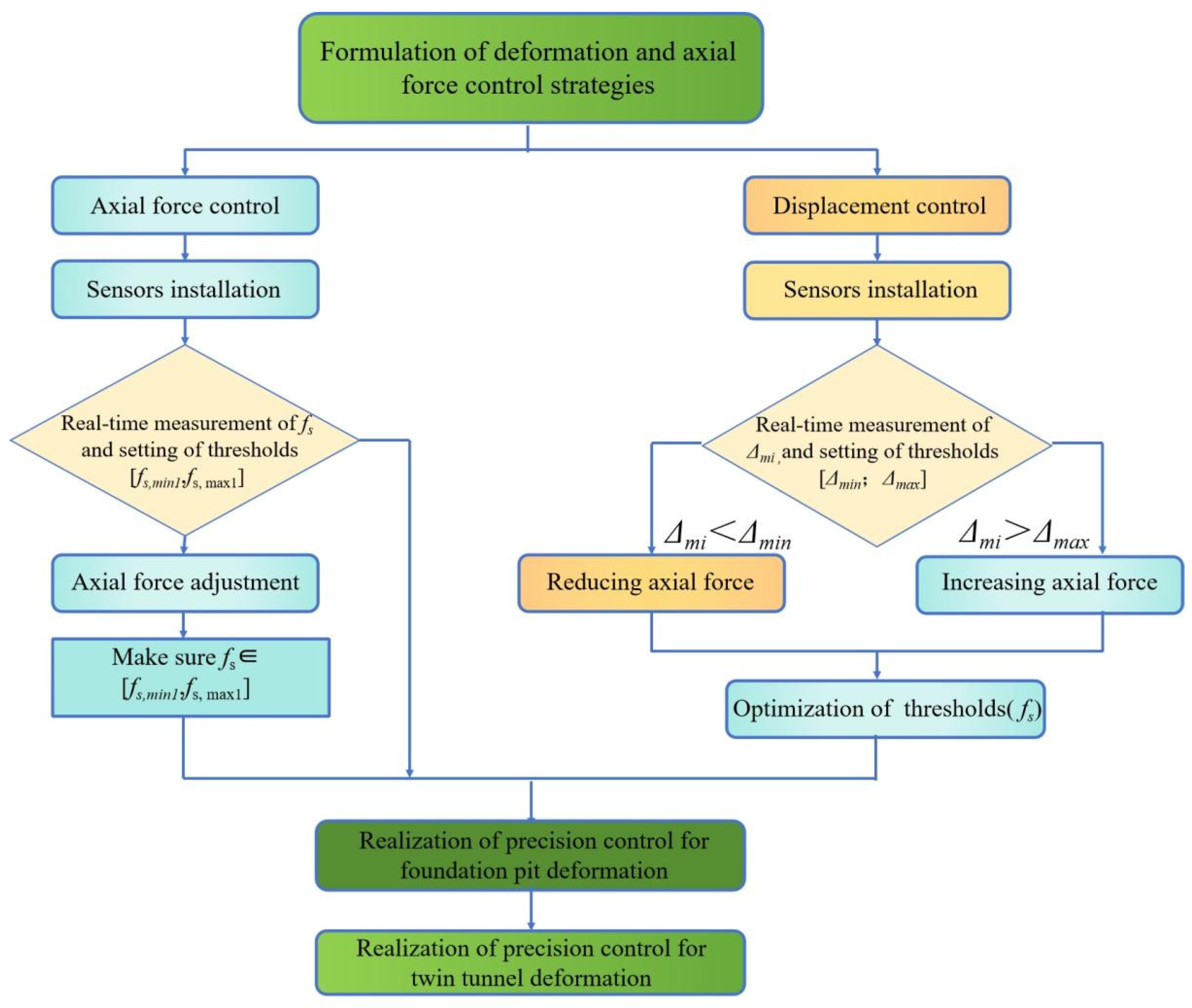
To compensate for the above deficiencies, this study implements synchronous active loading using a servo support system during the excavation of a deep foundation pit adjacent to metro tunnels. Based on the field monitoring data, it compares tunnel deformation responses in key stages before and after servo loading, focusing on variations in vertical displacement, horizontal displacement, and horizontal convergence. The weakening effect of servo supports on tunnel deformation during critical excavation stages is quantitatively evaluated, verifying their active control capability in practical engineering. The results provide a valid reference for a support system design and the controlled construction of deep foundation pits adjacent to existing metro tunnels.
5. Field Measurement Analysis of Deformation of Adjacent Metro Tunnels (Up-Line/Down-Line)
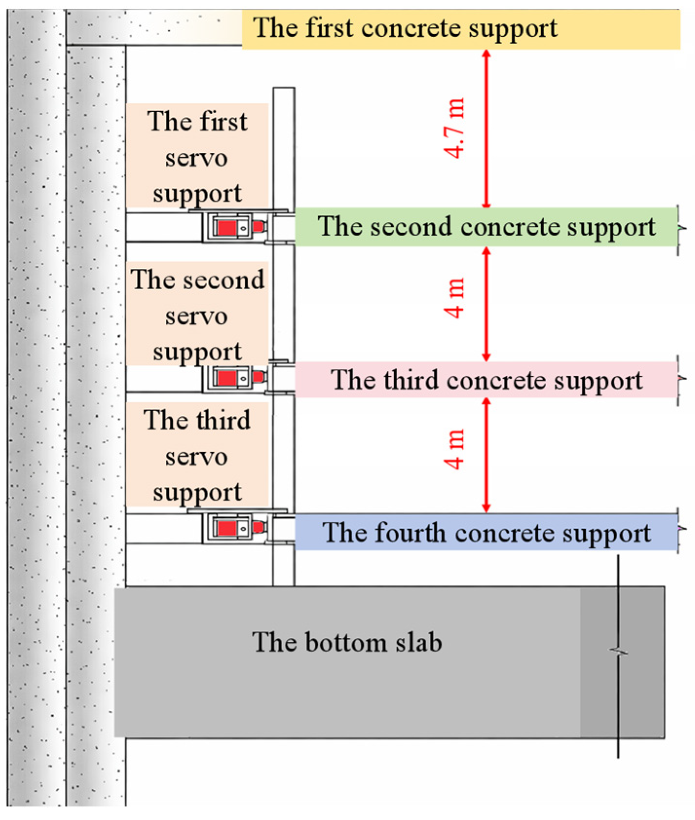
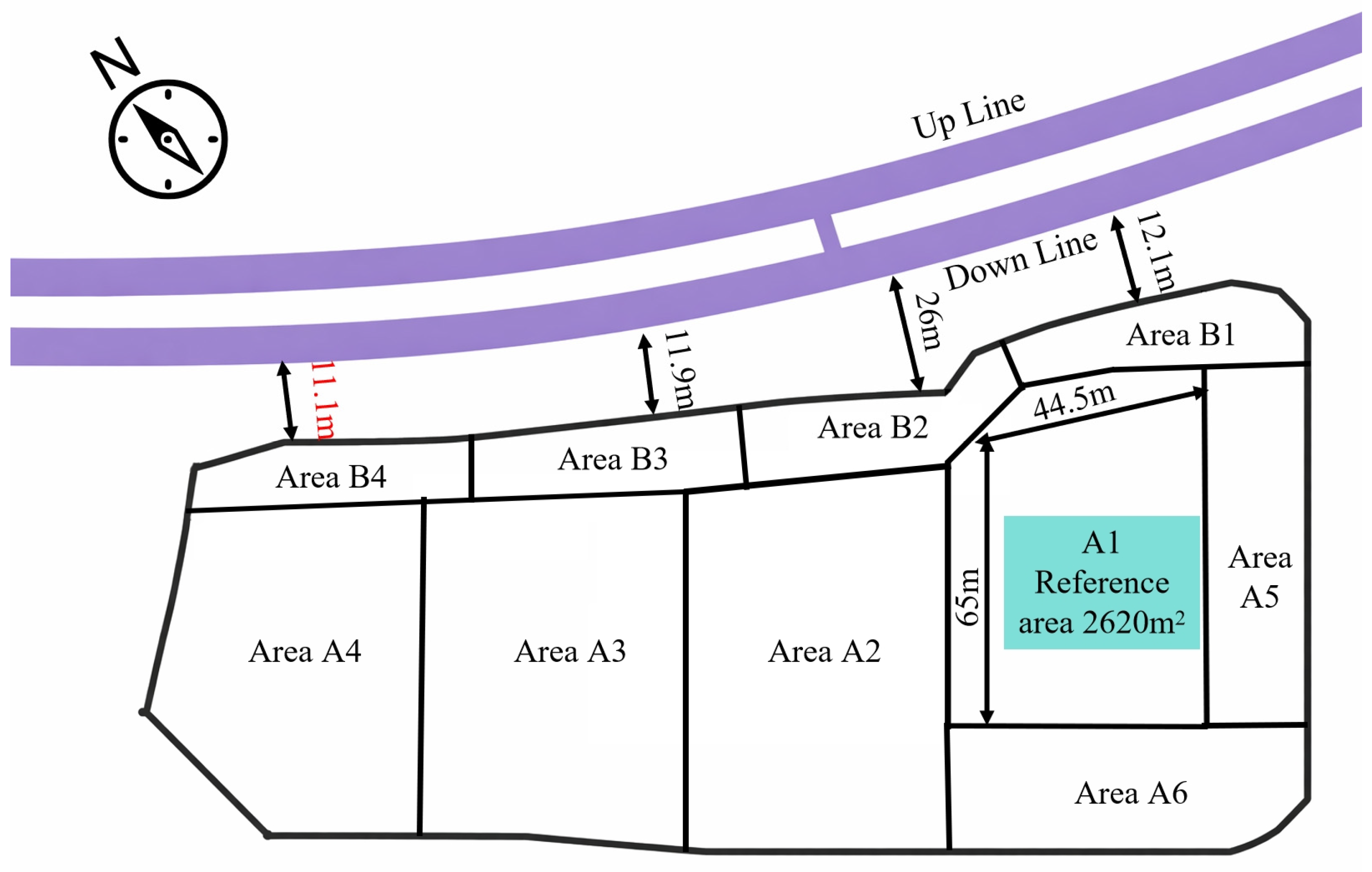
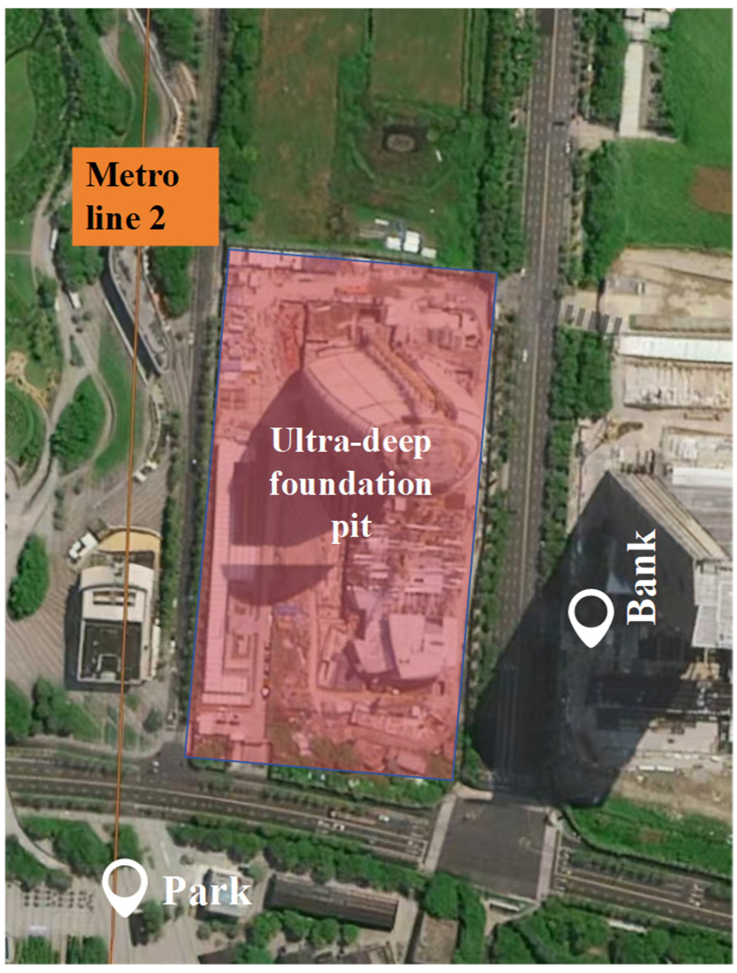
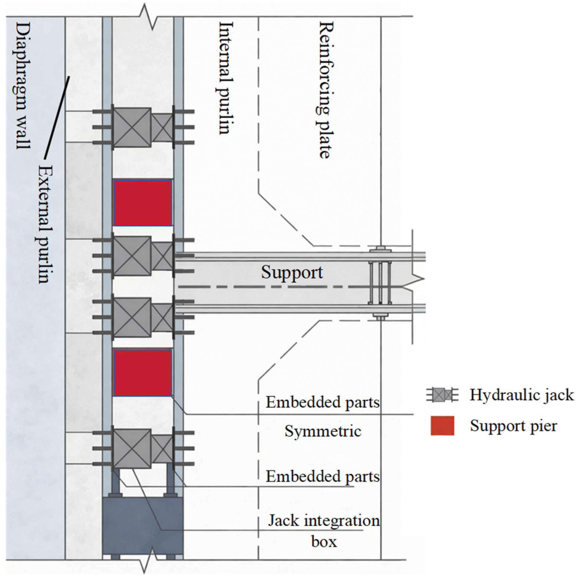
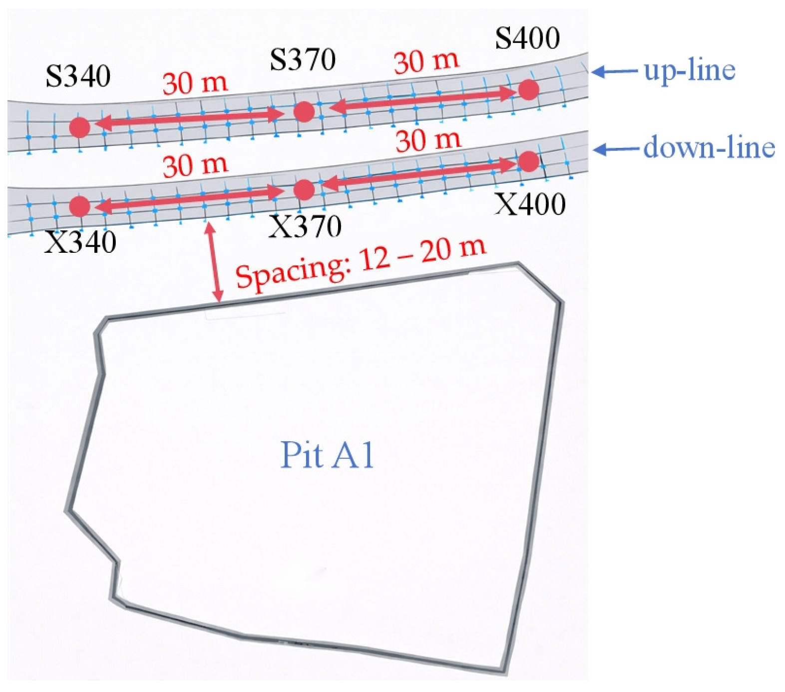
Pit A1 was excavated from 8 March to 5 August 2023, with a maximum depth of 19.3 m. The first support is a conventional concrete support, and the second–fourth are servo concrete supports with active pre-loading before subsequent layer excavation; the fifth support is a conventional concrete bottom slab. The second–fourth supports (working conditions S4, S7, S10) each contain 20 jacks per layer, with the servo load values per meter being 849 kN/m, 920 kN/m, and 990 kN/m (
Table 3), respectively, and increasing the burial depth to counteract rising lateral soil pressure. Each jack has a maximum loading capacity of 3500 kN and a maximum stroke of 0.2 m. Monitoring data were analyzed using a “7-days before loading—7-days after loading” symmetric time window to isolate servo effects from long-term excavation trends. This short-term window is considered appropriate, as deformation monitoring data are typically treated as time-series data, and short-duration intervals are commonly adopted to capture the immediate response of surrounding structures to construction disturbances [
26,
27]. Moreover, the 7-day window ensures sufficient data points under daily monitoring frequency, providing a balance between sensitivity to short-term changes and robustness against data fluctuations. Deformation rates 7 days before (
δ7) and after (
η7) loading were calculated for the representative up-line/down-line measuring point 370 (Equations (1) and (2)), where x is the loading-day deformation value, and
xa7/
xb7 are deformation values 7 days before/after loading.
5.1. Field Measurement Analysis of Tunnel Vertical Displacement
During the foundation pit excavation and servo loading process, soil unloading will induce vertical heave or settlement of adjacent tunnels. Vertical displacement can directly reflect the response degree of the tunnel structure due to the disturbance from the foundation pit excavation, which is also a key indicator for evaluating the control effect of the servo supports.
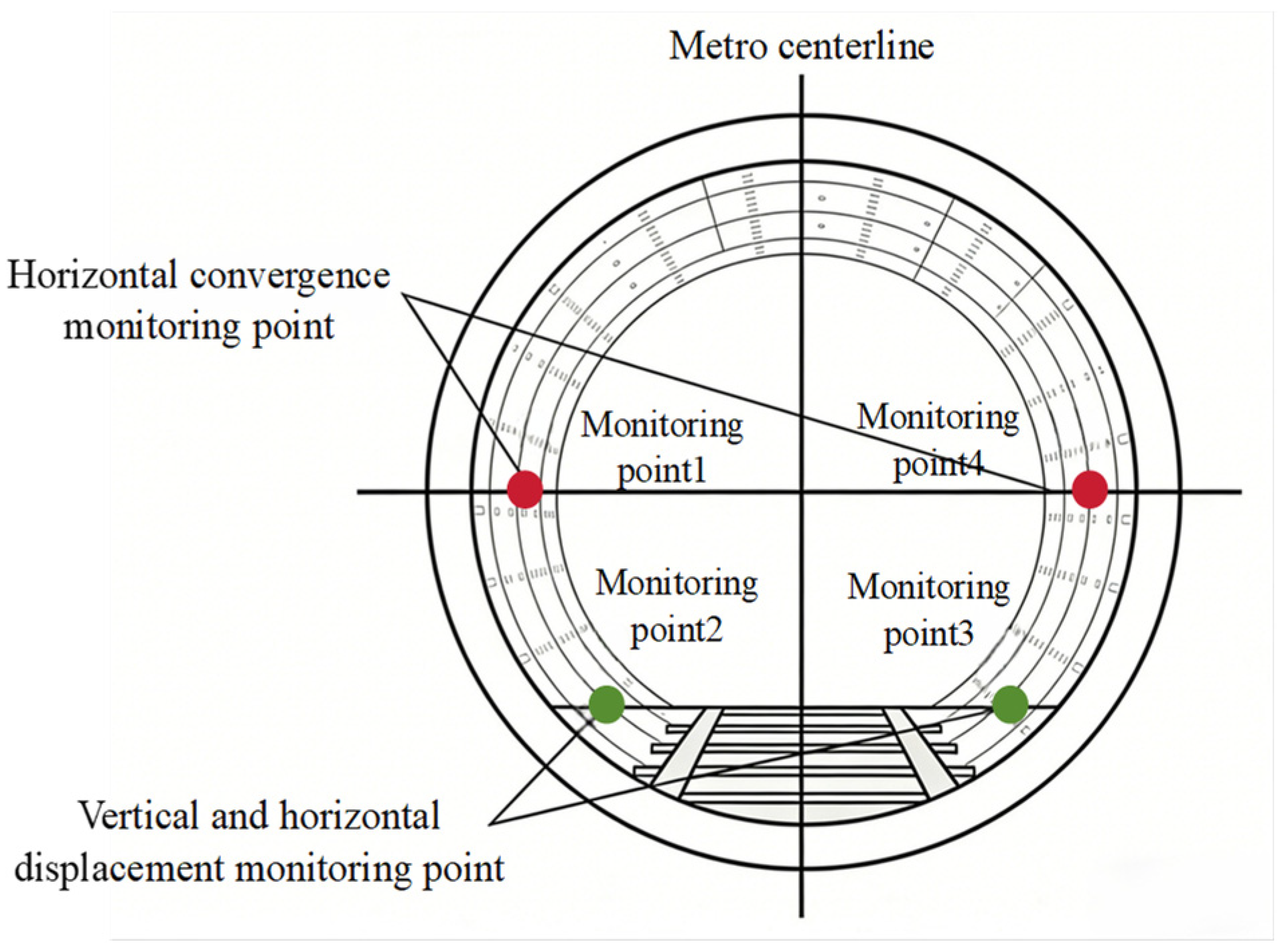
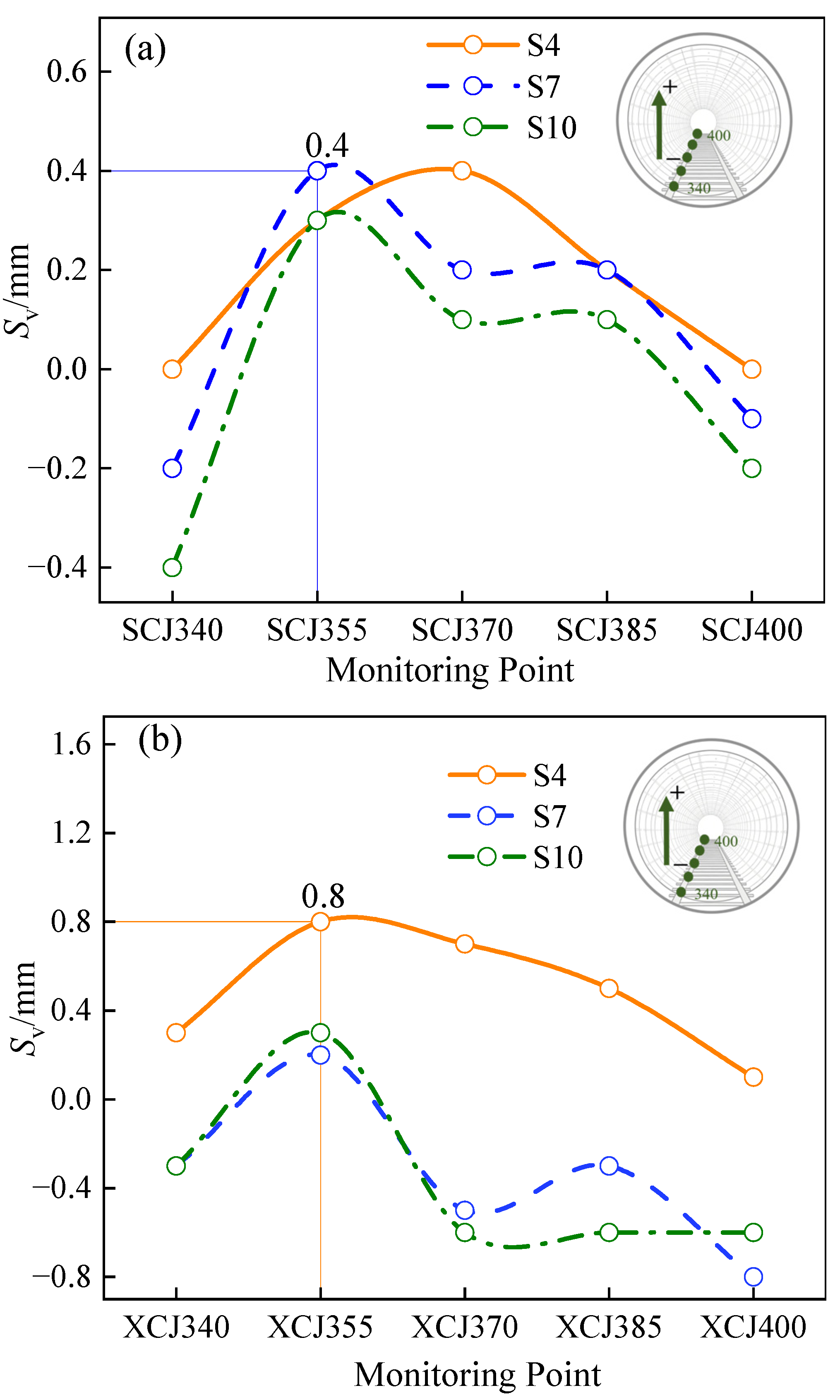
Five monitoring points are selected for the up-line and down-line tunnels, respectively. The variation curves of tunnel vertical displacement are shown in
Figure 10, where the positive vertical displacement Sv represents heave, while the negative vertical displacement represents settlement. The reading values of all measuring points are zero on the day of foundation pit excavation. The distribution rules of vertical displacement at each measuring point are as follows:
(1) The displacement curves of both the up-line and down-line tunnels show the spatial characteristic that “the vertical displacement reaches the peak value near the measuring point 355, and gradually decreases towards both ends along the line”.
(2) The vertical displacement of the up-line tunnel is generally in the range of −0.4–0.4 mm, with little difference in the curve shapes of the three working conditions, and the maximum value of approximately 0.4 mm occurs in the S7 stage. The vertical displacement amplitude of the down-line tunnel is slightly larger, ranging from −0.8 to 0.8 mm overall, and the maximum value of about 0.8 mm appears at XCJ355 in the S4 stage.
(3) From the perspective of safety, the maximum vertical displacement of the tunnel is only 0.8 mm, which is significantly less than the vertical displacement early warning index (i.e., 10 mm) commonly used in the protection monitoring of existing urban rail transit structures [
28]. Therefore, it can be determined that the vertical deformation of the tunnel under various working conditions is within a reasonable and safe control range.
Figure 10.
Vertical displacement curves of tunnel measuring points under various working conditions: (a) up-line; (b) down-line.
Figure 10.
Vertical displacement curves of tunnel measuring points under various working conditions: (a) up-line; (b) down-line.
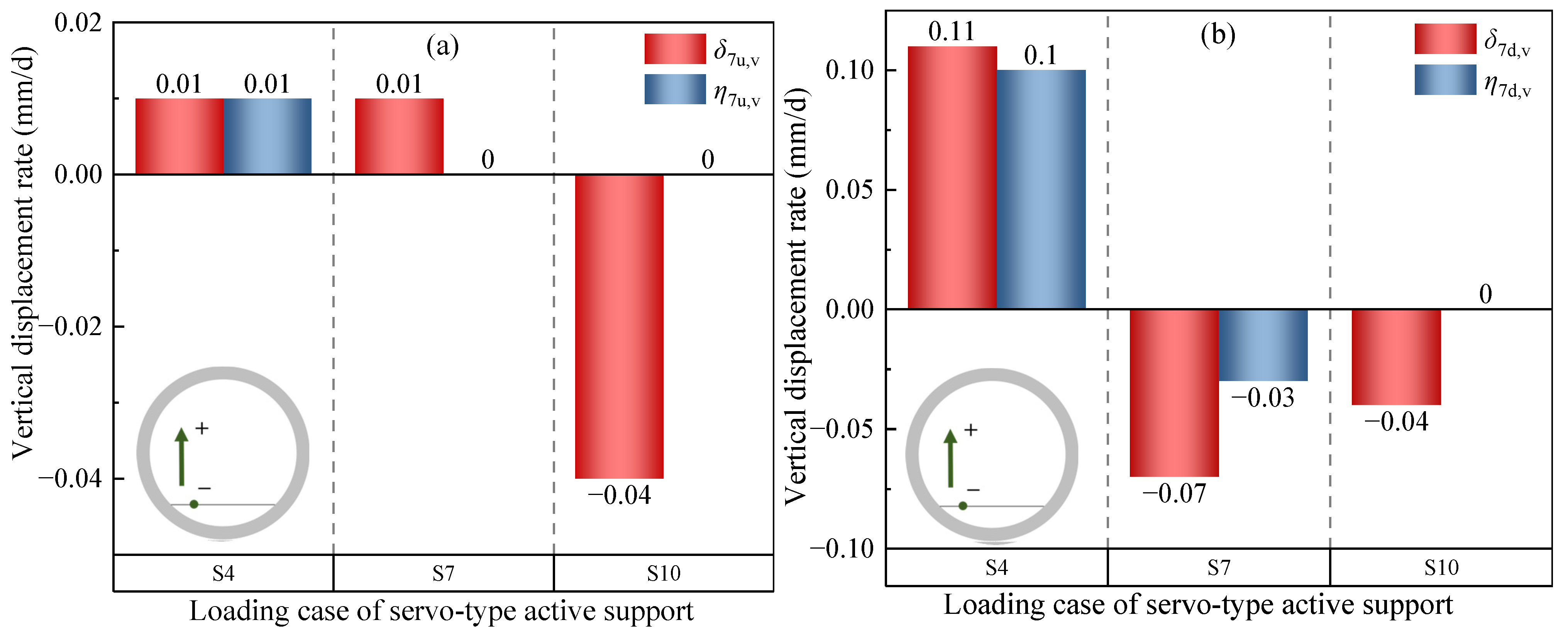
To further identify the regulatory effect of servo support loading on the development process of vertical deformation, this study compares the vertical displacement rates of measuring point 370 before and after loading under various support conditions (see
Figure 11). In the subsequent context,
δ7u,v and
η7u,v represent the vertical displacement rates of the up-line 7 days before and after loading, while
δ7d,v,
η7d,v denote the vertical displacement rates of the down-line tunnels 7 days before and after loading. The variation patterns of the vertical displacement rate are as follows:
(1) For the up-line tunnel in the S4 stage, both δ7u,v and η7u,v are 0.01 mm/d, with no significant difference before and after loading. However, with the increase of support loading depth in the S7 stage, δ7u,v remains 0.01 mm/d, while η7u,v decreases to 0. In the S10 stage, δ7u,v of the up-line tunnel is −0.04 mm/d, and η7u,v drops to 0 mm/d, indicating that the control effect of deep servo support loading is significantly better than that of the shallow support stage.
(2) The down-line tunnel shows a more significant response to servo support loading. In the S4 stage, δ7d,v is 0.11 mm/d, and η7d,v decreases to 0.10 mm/d, with a small variation range. In the S7 stage, the vertical displacement rate decreases from −0.07 mm/d before loading to −0.03 mm/d after loading, a reduction of approximately 57%, indicating that loading has an obvious inhibitory effect. In the S10 stage, δ7d,v is −0.04 mm/d, and η7d,v drops to 0 mm/d, effectively suppressing the development rate of vertical deformation of the tunnel.
(3) The control effect of servo supports on tunnel vertical deformation is mainly reflected in reducing the deformation development rate. Shallow loading has a limited effect on the vertical displacement rate. After the loading of the fourth servo support, the vertical displacement of both the up-line and down-line tunnels is effectively suppressed, and the vertical response of the tunnel enters a controlled and stable state.
Figure 11.
Tunnel vertical displacement rate changes before and after each support loading: (a) up-line; (b) down-line.
Figure 11.
Tunnel vertical displacement rate changes before and after each support loading: (a) up-line; (b) down-line.
5.2. Field Measurement Analysis of Tunnel Horizontal Displacement
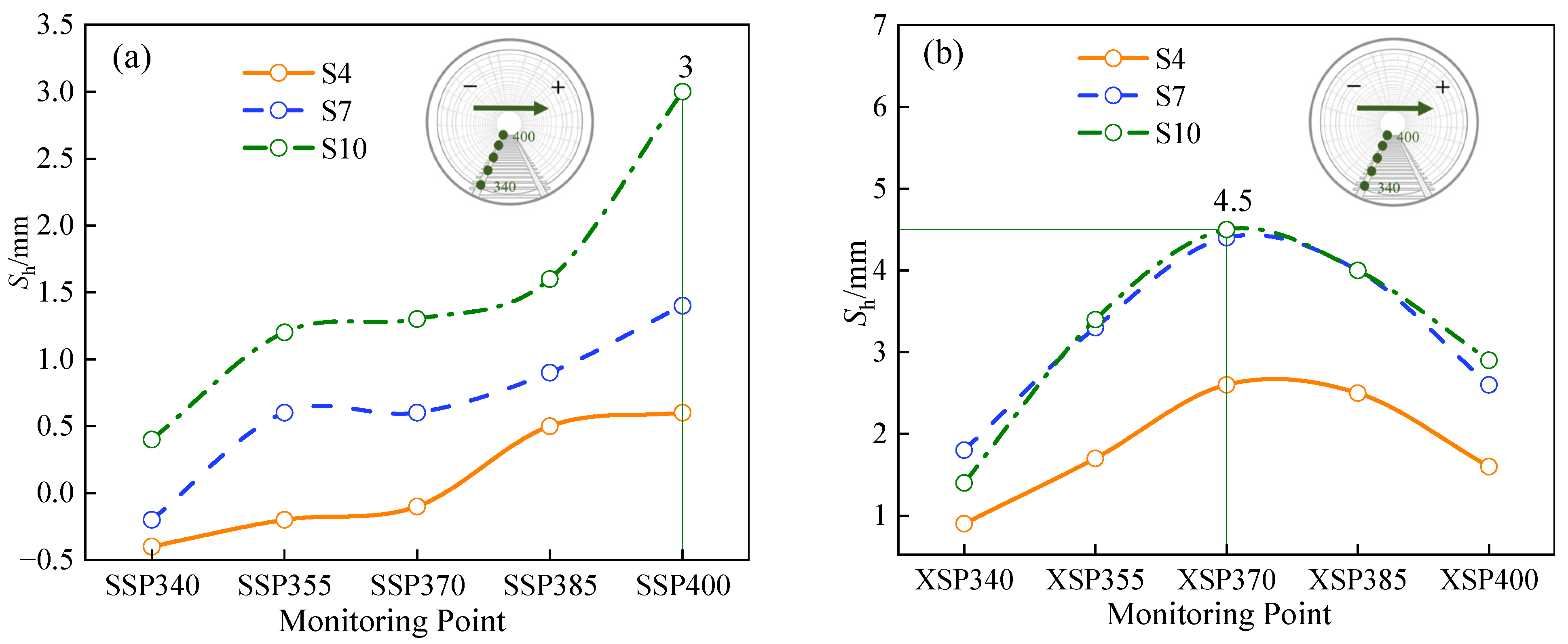
Figure 12 shows the variation curves of tunnel horizontal displacement Sh. It should be noted that a positive value indicates displacement towards the foundation pit, while a negative value indicates displacement away from the foundation pit. The horizontal displacement of all measuring points is zero before foundation pit excavation. The distribution rules of horizontal displacement at each measuring point are as follows:
(1) Under the condition of servo support loading, both the up-line and down-line tunnels mainly displace horizontally towards the foundation pit.
(2) The Sh of the up-line tunnel generally shows a trend of gradual increase with the increase of measuring point number. Among them, the horizontal displacement of SSP400 reaches the maximum value under various working conditions, reaching approximately 0.5‰D (i.e., 3.0 mm) in the S10 loading stage, while the displacement amplitude of the SSP340 measuring point far from the foundation pit is small.
(3) The horizontal displacement amplitude of the down-line tunnel is significantly larger than that of the up-line tunnel. The peak horizontal displacement of the middle measuring point XSP370 of the foundation pit reaches 0.75‰D (i.e.,4.5 mm), which is 1.5 times that of the maximum horizontal displacement of the up-line tunnel. Moreover, the down-line tunnel is closer to the foundation pit and is more strongly disturbed by foundation pit construction.
Figure 12.
Horizontal displacement of the tunnel during the loading of each servo active support: (a) up-line; (b) down-line.
Figure 12.
Horizontal displacement of the tunnel during the loading of each servo active support: (a) up-line; (b) down-line.
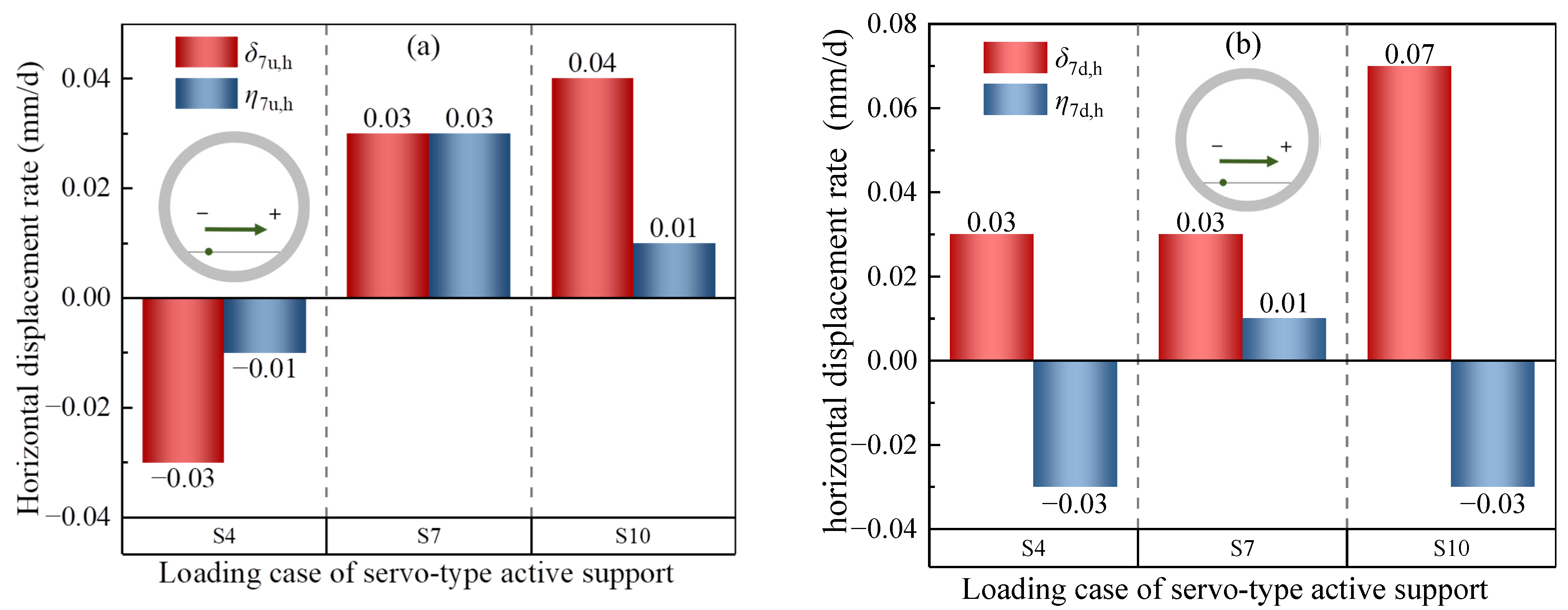
Figure 13 compares the horizontal displacement rates of measuring point 370 7 days before and after loading under different working conditions. In the subsequent context,
δ7u,h and
η7u,h represent the horizontal displacement rates of the up-line 7 days before and after loading, while
δ7d,h and
η7d,h denote the horizontal displacement rates of the down-line tunnels 7 days before and after loading. The variation patterns of the horizontal displacement rate are as follows:
(1) For the up-line tunnel, the effect is not obvious in the shallow support loading stage. While in the S10 stage, the horizontal displacement rate 7 days before loading is 0.04 mm/d, and it decreases to 0.01 mm/d 7 days after loading, a reduction of about 75%, indicating that the deep servo support effectively suppresses the continuous horizontal displacement of the up-line tunnel towards the foundation pit.
(2) The down-line tunnel exhibits a more significant response to servo support loading. In the S10 stage, δ7d,h before loading reaches 0.07 mm/d, and η7d,h after loading drops to −0.03 mm/d, showing a trend of deformation transformation from “continuous displacement towards the foundation pit” to “rebound adjustment”.
Figure 13.
Tunnel horizontal displacement rate changes before and after each support loading: (a) up-line; (b) down-line.
Figure 13.
Tunnel horizontal displacement rate changes before and after each support loading: (a) up-line; (b) down-line.
Although the overall horizontal displacement of the tunnel during foundation pit excavation is mainly towards the foundation pit, servo supports can significantly reduce the development rate of horizontal displacement. In addition, deep servo supports can effectively limit the further inward displacement of the retaining structure, bringing the development of tunnel horizontal displacement into a stable state.
5.3. Field Measurement Analysis of Tunnel Horizontal Convergence
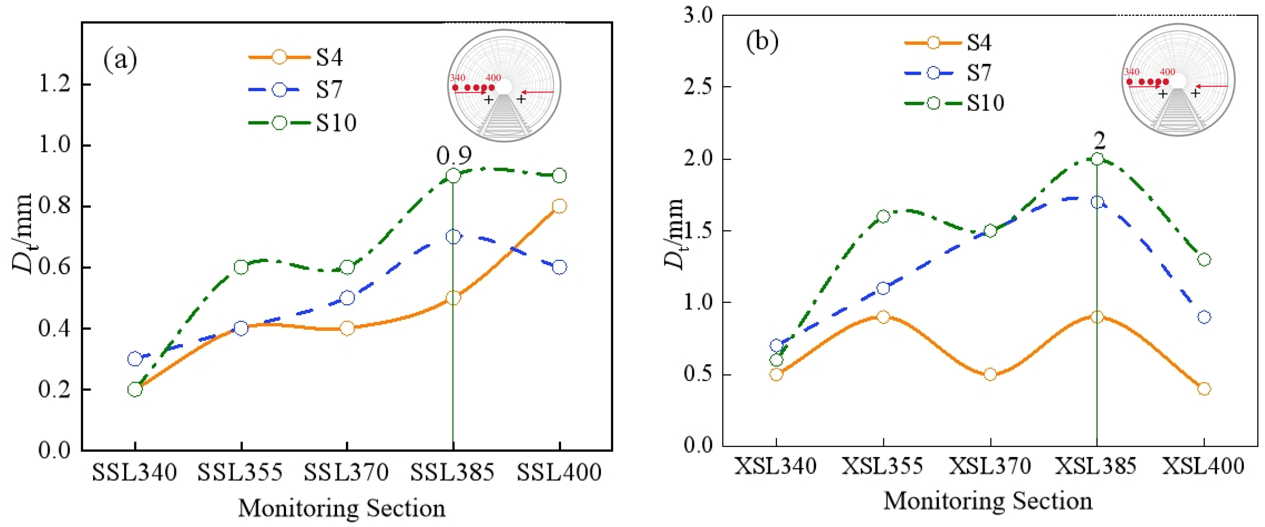
Figure 14 shows the variation trend of tunnel horizontal convergence
Dt (i.e., the relative horizontal displacement between two points in the segments at the same elevation of the tunnel center) under various servo loading conditions. It should be mentioned that a positive value indicates a decrease in horizontal diameter (i.e., inward convergence), while a negative value indicates an increase in horizontal diameter (i.e., outward convergence). It can be seen from
Figure 14 that:
(1) During the whole process of synchronous implementation of foundation pit excavation and servo support, the horizontal convergence values of both the up-line and down-line tunnels are positive in general, indicating that the tunnels are in a state of lateral compression.
(2) The horizontal convergence values of each measuring point on the up-line tunnel are generally small, mainly distributed in the range of 0.3–0.9 mm, and show a slow accumulation characteristic with the advancement of construction.
(3) The horizontal convergence amplitude of the down-line tunnel is significantly larger than that of the up-line tunnel, showing an “M” shape. The convergence value of measuring point XSL385 is the most prominent, with the maximum value exceeding 2 mm in the period of the last servo loading (i.e., S10). This indicates that the down-line tunnel, being closer to the foundation pit, is more susceptible to the combined influence of displacement of the retaining structure and lateral soil pressure concentration, and its lateral compression effect is significantly stronger than that of the up-line tunnel.
Figure 14.
Horizontal convergence of the tunnel during the loading of each servo active support: (a) up-line; (b) down-line.
Figure 14.
Horizontal convergence of the tunnel during the loading of each servo active support: (a) up-line; (b) down-line.
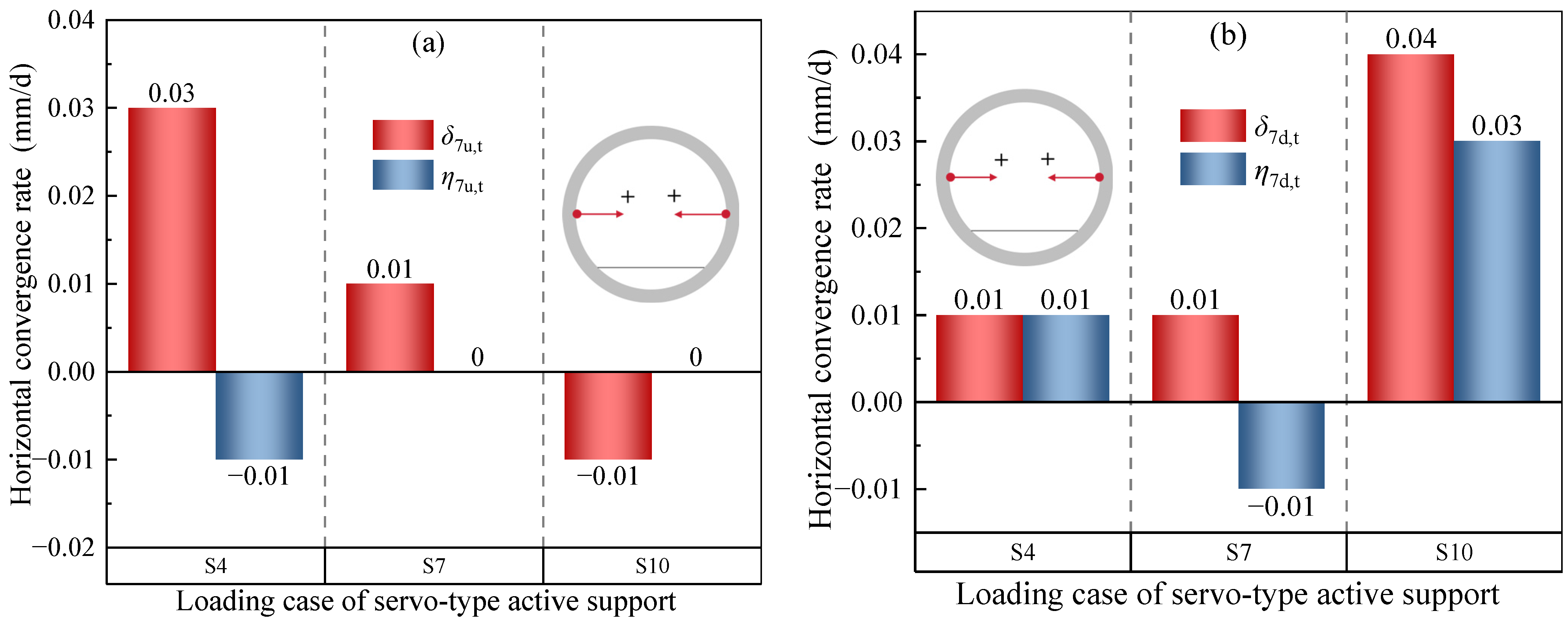
Measuring point 370 is also selected for the analysis, where
δ7u,t and
η7u,t represent the horizontal convergence rates of the up-line 7 days before and after loading, while
δ7d,t and
η7d,t denote the horizontal convergence rates of the down-line 7 days before and after loading. It can be seen from
Figure 15 that:
(1) For the up-line tunnel in the S4 stage, the horizontal convergence rate δ7u,t within 7 days before loading is 0.03 mm/d, and it turns to −0.01 mm/d 7 days after loading, which weakens the development trend of tunnel lateral compression in this stage. Subsequently, in the third and fourth support loading stages, the post-loading rate decreases to 0 mm/d, and the stress state tends to be stable.
(2) For the down-line tunnel in the S4 stage, the rates before and after loading are both 0.01 mm/d, indicating that the shallow support has a limited immediate regulatory effect on the lateral compression of the down-line tunnel. However, after the loading of the second servo support, the rate changes from 0.01 mm/d to −0.01 mm/d, indicating that the support begins to exert an inhibitory effect on convergence accumulation. In the third servo support loading stage, δ7d,t reaches 0.04 mm/d, and η7d,t decreases to 0.03 mm/d, with its development rate being reduced.
(3) The horizontal convergence of the tunnel generally shows the characteristics of continuous compression and gradual accumulation during foundation pit excavation. Servo supports function by reducing the convergence development rate and delaying the accumulation process. In the third servo support loading stage (i.e., S10), the convergence rate of the up-line tunnel decreases to 0 mm/d, and the rate of the down-line tunnel is reduced. Its active axial force can effectively weaken the transmission intensity of the lateral soil pressure to the tunnel, thereby improving the lateral stress state of the tunnel and slowing down convergence accumulation.
Figure 15.
Horizontal convergence rate changes of the tunnel before and after each support loading: (a) up-line; (b) down-line.
Figure 15.
Horizontal convergence rate changes of the tunnel before and after each support loading: (a) up-line; (b) down-line.
5.4. Mechanism Analysis
The above field measurement results show that under the construction mode of synchronous implementation of servo supports and foundation pit excavation, the vertical displacement, horizontal displacement, and horizontal relative convergence of the adjacent metro tunnels are all effectively controlled, and the deformation development rates are significantly lower than those of engineering cases characterized by “implementing servo loading after the completion of foundation pit excavation” in the existing literature [
29,
30,
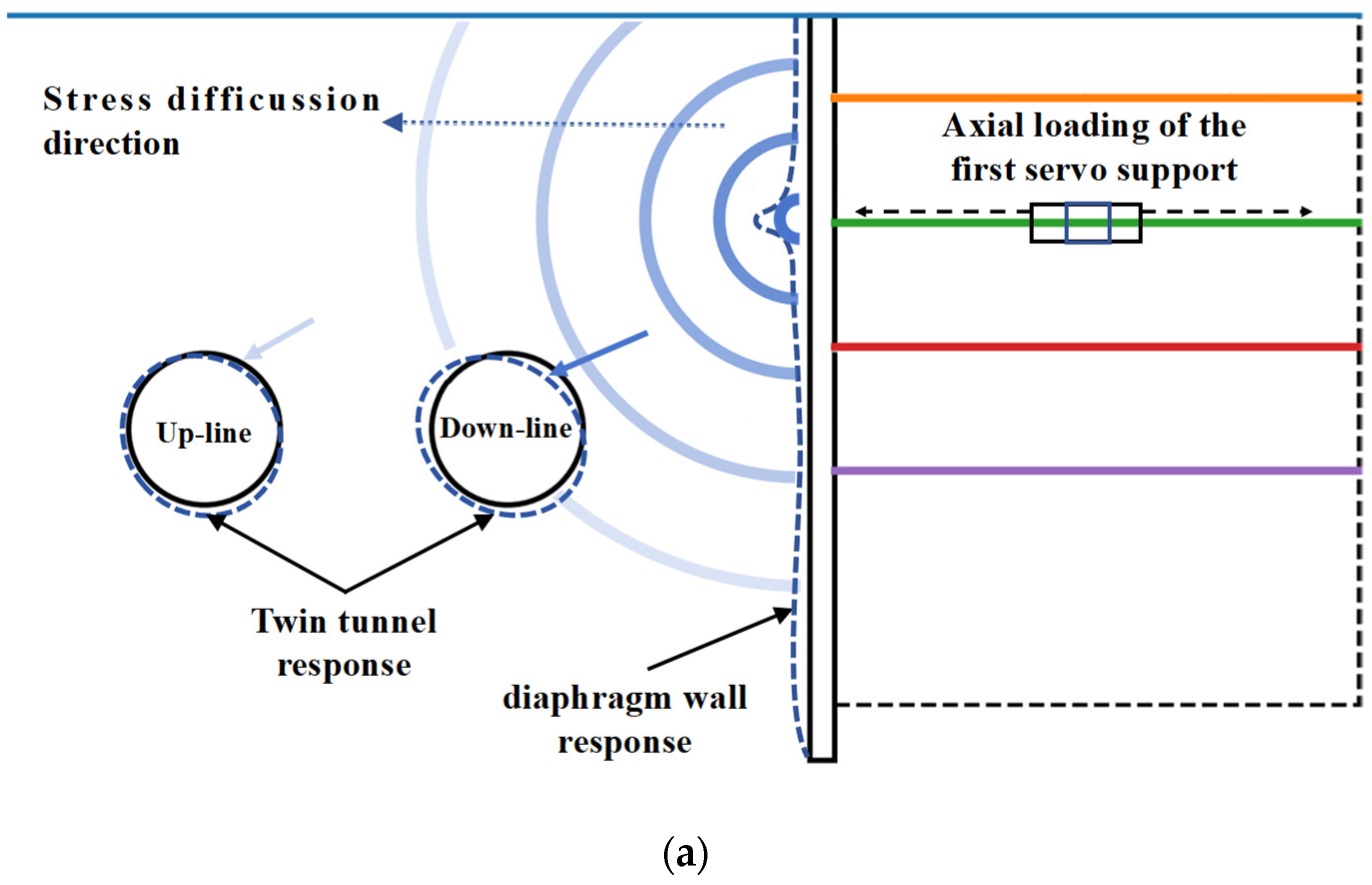
31]. However, after the application of servo supports, the overall displacement of the tunnel is still mainly “towards the foundation pit”. The main mechanism is that the servo supports prop up the retaining structure in advance, reduces the inward movement of soil towards the pit, and transforms the tunnel deformation from “continuous increase” to “slowing down or even stabilizing”. As shown in
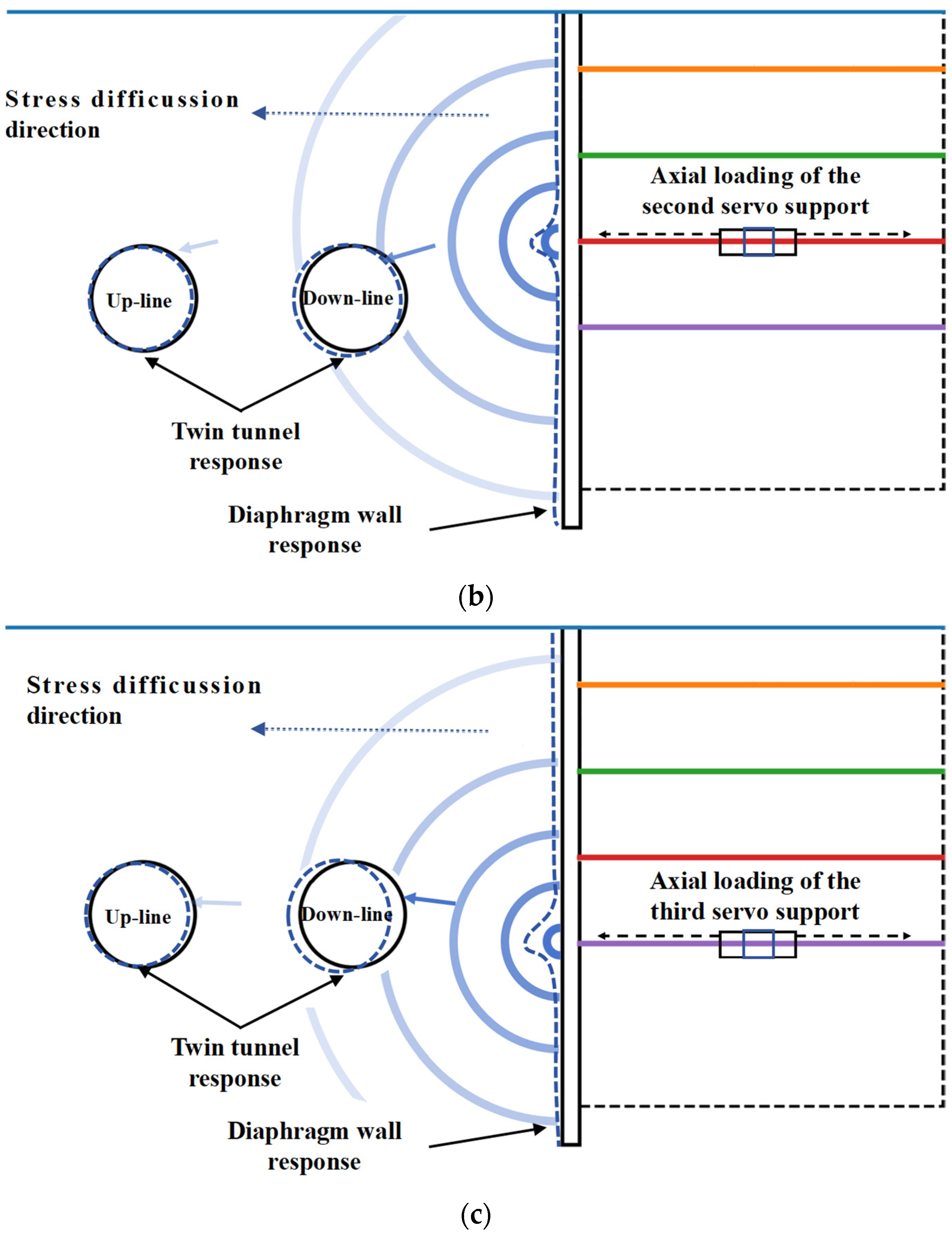
Figure 16, the effects of servo loading in each stage can be explained as follows:
(1) When the second servo support is loaded (see
Figure 16a), its position is obliquely above the tunnel and far away from the tunnel, mainly serving to suppress the inward displacement of the upper part of the retaining structure. At this time, the impact caused by foundation pit excavation will still propagate to the deep part, and the tunnel may still undergo a certain degree of displacement and deformation. Therefore, the direct control effect of the second servo loading on tunnel deformation is relatively limited, and its main role is to establish the support system and lay the foundation for subsequent deep control.
(2) The loading position of the third servo support is deeper. After loading, the inward displacement trend of the retaining structure is further restricted, and the inward squeezing of soil towards the pit is also weakened. Therefore, the development rate of the tunnel’s horizontal displacement will decrease significantly, and the vertical displacement will be more likely to stabilize. At this stage, the control effect of the servo supports on tunnel deformation begins to be significantly reflected.
(3) When the fourth servo support is loaded, the support depth is close to the tunnel burial depth, which has the most direct and effective inhibitory effect on the deep inward displacement of the retaining structure. Since tunnel deformation is often mainly caused by deep soil unloading and lateral movement, the servo supports need to apply a larger axial force under the influence of deep soil pressure. After deep servo loading, the impact transmitted to the tunnel is greatly reduced, the growth rate of tunnel horizontal displacement will slow down significantly, and even a local “rebound adjustment” trend will appear. The advantage of the fourth loading lies in its control over the “most critical source of deep deformation”, bringing the tunnel deformation into a more stable and controlled state, which is the fundamental reason for its obvious control effect.
In summary, the second servo loading mainly plays an early constraint role, while the stress transmission distance is long, resulting in a weak impact on the tunnel. The third servo loading begins to significantly reduce the tunnel deformation growth rate. The fourth servo loading, with the closest loading path to the tunnel, can more effectively restrict the transmission of deep lateral displacement to the tunnel and achieve the best comprehensive control effect.
Figure 16.
Deformation mechanism diagram of adjacent tunnels under servo-driven active loading: (a) S4; (b) S7; and (c) S10.
Figure 16.
Deformation mechanism diagram of adjacent tunnels under servo-driven active loading: (a) S4; (b) S7; and (c) S10.
6. Conclusions
This study investigates the deformation characteristics of the double-line metro tunnels during the excavation of the adjacent foundation pit. Based on the monitoring data, the tunnel displacement and convergence under the coupling effect of servo supports loading and deep foundation pit excavation were systematically analyzed. The mechanism for controlling tunnel displacement through the active loading of servo supports was also proposed. The main conclusions are summarized as follows:
(1) Under the condition of “synchronous implementation of excavation—servo support” in pit A1, the vertical displacement of the adjacent double-line tunnels is generally in the range of −0.8–0.8 mm, with a maximum value of only 0.8 mm, which is significantly less than the vertical displacement early warning index of existing tunnels, indicating that the vertical deformation is within a safe and controllable range.
(2) The overall horizontal displacement of the tunnel is mainly towards the foundation pit, and the response of the down-line tunnel is significantly stronger. The maximum horizontal displacement of the up-line tunnel occurs at the easternmost side, reaching 0.5‰D in the S10 stage. The peak value of the down-line tunnel is at the position closest to A1 in the middle of the foundation pit, reaching 0.75‰D, which is about 1.5 times that of the corresponding position of the up-line tunnel, indicating that the down-line tunnel is more sensitive to construction disturbances.
(3) The horizontal convergence of the tunnel is positive under all working conditions, showing continuous lateral compression accumulation. The convergence value of the up-line tunnel is mainly 0.3–0.9 mm, while that of the down-line tunnel is larger and concentrated in the middle section, with the maximum value exceeding 2 mm in the later construction period.
(4) The deformation rate changes in the “7 days before loading—7 days after loading” time window indicate that the primary function of the servo support system is to mitigate the rate of tunnel deformation, thereby restraining excessive displacement during excavation, and the effect of deep loading is the most prominent. After the loading of the third servo support, the horizontal displacement rate of the up-line tunnel decreases by about 75%. The horizontal displacement of the down-line tunnel changes from 0.07 mm/d to −0.03 mm/d, transforming from continuous lateral displacement to rebound adjustment. The vertical displacement rate of both lines decreases to 0, and the deformation enters a stable and controlled state.
(5) Due to the third servo support loading depth being closest to the tunnel burial depth, it has the most direct inhibitory effect on the deep lateral displacement. Moreover, it achieves the best comprehensive control effect on the double-line tunnels, which is reflected in the significant reduction of the growth rates of horizontal displacement and convergence, and the transformation of tunnel deformation from “continuous accumulation” to “significant deceleration and stabilization”.
It is important to mention that, compared to the traditional non-servo support system, although the servo support system increases the partial cost due to the servo system itself, the overall cost of the whole retaining structure is significantly reduced by adopting the servo system. For this project, in order to meet the deformation control requirements, the thickness of the concrete diaphragm wall was optimized from 1.0 m to 0.8 m by adopting the servo support system, resulting in a cost reduction of approximately 20% compared to the traditional support systems. In addition, the concrete consumption of the retaining structure has been effectively reduced, which reasonably lowers carbon emissions and brings considerable energy-saving benefits. Furthermore, the servo system can be dismantled immediately when the underground structure has been completed. After routine maintenance, the dismantled servo system can be reused, resulting in relatively low long-term maintenance costs.
It should also be noted that the deformation behavior of the adjacent metro twin tunnels under the coupled effects of servo support and deep excavation is governed by complex soil-structure interaction mechanisms. This study primarily focuses on the short-term deformation characteristics induced during excavation and synchronous servo loading. However, further investigations are required to establish a comprehensive mechanical model of the retaining structure–soil–tunnel interaction system, to elucidate the spatial distribution characteristics of deformation over the entire tunnel section, and to reveal the long-term deformation evolution after project completion. In particular, future research will provide long-term monitoring data, statistical analysis, and analytical insights into the stabilization process of tunnel deformation over time.





 ,
,