Article

Study on Mechanical Properties of Coarse-Fine Polypropylene Fiber Blended Concrete

1
School of Civil Engineering, Chongqing University, Chongqing 400045, China
2
Zhejiang Jinggong Steel Building Group Co., Ltd., No. 1587 Jianhu Rd, Shaoxing 312000, China
*
Author to whom correspondence should be addressed.
Buildings 2025, 15(16), 2971; https://doi.org/10.3390/buildings15162971
Submission received: 9 June 2025 / Revised: 8 August 2025 / Accepted: 19 August 2025 / Published: 21 August 2025

Abstract

Polypropylene fiber, as a micro-scale reinforcement material, has been widely recognized for its ability to effectively inhibit crack propagation during the service life of concrete, thereby enhancing both its crack resistance and durability. This study presents an experimental investigation of the mechanical properties of polypropylene fiber-reinforced concrete specimens. The primary objective of this study was to assess the influence of varying fiber lengths and volumetric fiber contents on the load-bearing behavior of concrete. Seven sets of concrete specimens with different polypropylene fiber parameters (dosage and length) were prepared and subjected to a series of tests, including compressive strength, splitting tensile strength, flexural strength, and axial compressive stress–strain behavior. Specifically, coarse polypropylene fibers with two lengths (30 mm and 50 mm) and three dosages (0.5%, 1%, and 1.5%) were investigated. Experimental results facilitated the identification of the optimal fiber dosage and length at which the mechanical properties of the concrete specimens were maximized. Subsequently, a constitutive model for polypropylene fiber-reinforced concrete was established. The analysis elucidated the relationships between the parameters within the constitutive model, axial compressive strength of the concrete, and characteristic fiber parameters. The derived formulations provide a theoretical foundation for subsequent finite element analyses of polypropylene-fiber-reinforced concrete.

1. Introduction

In recent years, an increasing number of new structures have emerged [1]. The application of prefabricated components has emerged as a hallmark of architectural industrialization. However, rising concerns regarding energy consumption and carbon emissions have accompanied this progress. In the carbon emission accounting of prefabricated components, building materials contribute over 95% of the total emissions, making the reduction of material usage a key strategy for carbon reduction [2]. Recent research on prefabricated construction has predominantly focused on the optimization and innovation of structural components, with extensive investigations covering material properties, connection techniques, and load-bearing capacities, all aimed at enhancing the overall performance of buildings [3]. Enclosure wall panels, which serve as core components in prefabricated buildings, perform the dual functions of structural support and thermal insulation. Consequently, the design and performance evaluation of these systems have become critical. In recent years, research on wall panels has evolved along two principal directions: one emphasizes material composition by testing various combinations of insulation and reinforcement materials to achieve an optimal balance between mechanical performance and thermal insulation, while the other analyzes the structural behavior of these panels under different loading conditions, including axial, bending, and seismic loads. For instance, Mustafaraj reinforced precast shear walls using polypropylene short fibers and meshes, demonstrating that the incorporation of polypropylene fibers significantly improved the in-plane load-carrying capacity of the masonry [4]. In another stream, David. C. Salmon comprehensively evaluated the mechanical performance of concrete composite sandwich panels and proposed a formula to accurately estimate panel deflections [5]. Joseph JDR’s experimental work revealed that the type of bending load markedly influences the flexural performance of sandwich panels and validated a predictive model for the ultimate bending capacity [6]. Ashraf A found that sandwich panels could effectively replace solid slabs to enhance structural performance, with experimental results closely aligned with numerical simulations [7]. Moreover, Benayoune A demonstrated that by optimally configuring truss-type steel connectors, the synergistic action between the interior and exterior concrete layers of sandwich panels can be achieved, endowing the panels with ductile failure characteristics as they approach ultimate load [8,9].
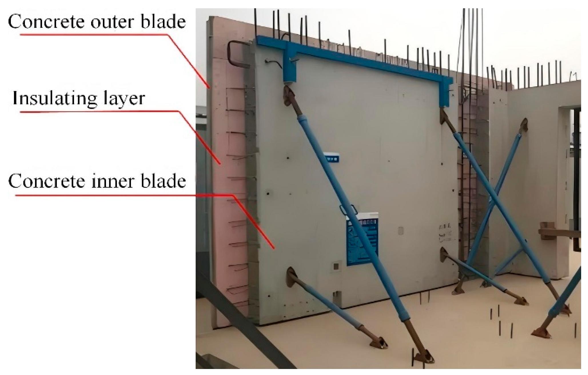
The current design of envelope wall panels is typically classified based on the presence and location of the insulation layer into single-material, interior-insulated, and exterior-insulated panels. However, these traditional insulation systems exhibit significant shortcomings in thermal performance, and both interior and exterior insulated panels are prone to insulation detachment and other safety issues, thereby impeding the advancement of energy-efficient and green-building practices. In contrast, composite sandwich wall panels integrate an insulation material within the concrete core, employing an intermediate insulation core to separate the inner and outer concrete skins. This configuration effectively reduces thermal losses due to alternating temperature gradients while fully leveraging the advantages of each constituent material, thus achieving a synergistic optimization of thermal insulation and structural performance. In a typical prefabricated composite sandwich wall panel (Figure 1), the inner and outer concrete skins are interconnected by preformed connectors, ensuring an integrated and stable structural system.
The concrete skins on both sides of sandwich panels are generally made of conventional concrete, which is characterized by low tensile strength, high brittleness, and susceptibility to cracking. To enhance the ductility of the panels, traditional designs often incorporate steel mesh reinforcement. However, this approach requires manual tying and precise positioning (Figure 2), which not only increases the construction complexity and cost but also prolongs the overall construction period.
The present study investigates the mechanical performance of concrete incorporating both coarse and fine polypropylene fibers. The primary objective of this study was to explore the feasibility of substituting traditional steel mesh reinforcements with polypropylene fibers, integrating them into prefabricated composite sandwich wall panels to ensure ductile behavior, enhance the overall performance of the panels, and extend their service life, thereby reducing the material input in prefabricated components. Polypropylene fibers, which serve as reinforcements, effectively restrain the propagation of microcracks during the service life of concrete, thereby improving its durability. Furthermore, owing to their light weight, corrosion resistance, and cost-effectiveness [10], polypropylene fibers are an ideal choice for augmenting the overall performance of prefabricated composite sandwich wall panels. Based on fineness, polypropylene fibers are classified as coarse or fine. Fine polypropylene fibers, characterized by their smaller diameters, help refine cracks, mitigate inherent structural defects, and inhibit crack initiation when introduced into concrete. In contrast, coarse polypropylene fibers with diameters ranging from 0.1 to 1.0 mm exhibit superior bond strength with the concrete matrix and possess higher individual fiber load capacity [11].
In recent years, numerous studies have explored the mechanical properties of polypropylene fiber (PF) reinforced concrete under various conditions, including different PF types, dosages, and concrete mix ratios. Compared to plain concrete, fiber-reinforced concrete exhibits enhanced durability and mechanical performance [12,13,14,15]. For instance, Habil Ahmad [16] demonstrated that the incorporation of PF improved the performance of hollow concrete specimens reinforced with GFRP bars, particularly in terms of ductility. Similarly, Cui [17] showed that the addition of PF to a concrete matrix significantly enhanced its fatigue strength. Zhou [18] observed that the reinforcement effect of PF on concrete strength was inferior to that of basalt fibers and proposed a method for optimizing fiber mix proportions. Jinliang Liu [19] conducted experiments involving the individual and combined use of glass fibers, PF, and mixed fibers, concluding that the synergy provided by mixed fibers yielded the most pronounced improvement in concrete performance. Additionally, Wang [20] elucidated the reinforcement mechanism of PF in concrete specimens. Research conducted by Song et al. [21] indicated that a volumetric PF dosage of 0.06% resulted in increases of 5.8%, 9.7%, and 1.5% in the compressive, splitting tensile, and flexural strengths, respectively, while Kakooei [22] reported a 32% enhancement in compressive strength at a PF dosage of 0.15%, marking the optimum improvement in compressive performance.
In summary, most current research on polypropylene fibers has concentrated on functional improvements and the production of ultra-fine fibers, while the mechanical properties of concrete mixed with polypropylene fibers still require further investigation. This study investigates the mechanical performance of concrete reinforced with a combination of coarse and fine polypropylene fibers. The experimental program examines the effects of varying coarse fiber lengths and dosages on the compressive strength, splitting tensile strength, flexural strength, and axial compressive stress–strain behavior of the concrete specimens. In this study, seven groups of concrete specimens were prepared by varying the volume fractions and lengths of the coarse and fine fibers. The volume dosage levels of the coarse polypropylene fibers were set at 0.5%, 1%, and 1.5%, with fiber lengths of 30 mm and 50 mm, respectively, while the dosage and length of the fine polypropylene fibers were fixed at 0.1% and 12 mm, respectively. Based on the experimental results, the optimum dosage and fiber length of coarse polypropylene fibers were determined, at which the concrete specimens exhibited the best overall mechanical properties, demonstrating an effective crack-arresting and toughening effect. Finally, an axial compressive constitutive model for polypropylene fiber-reinforced concrete, suitable for subsequent finite element analysis, was established.

2. Specimen Design and Grouping

2.1. Fiber and Concrete

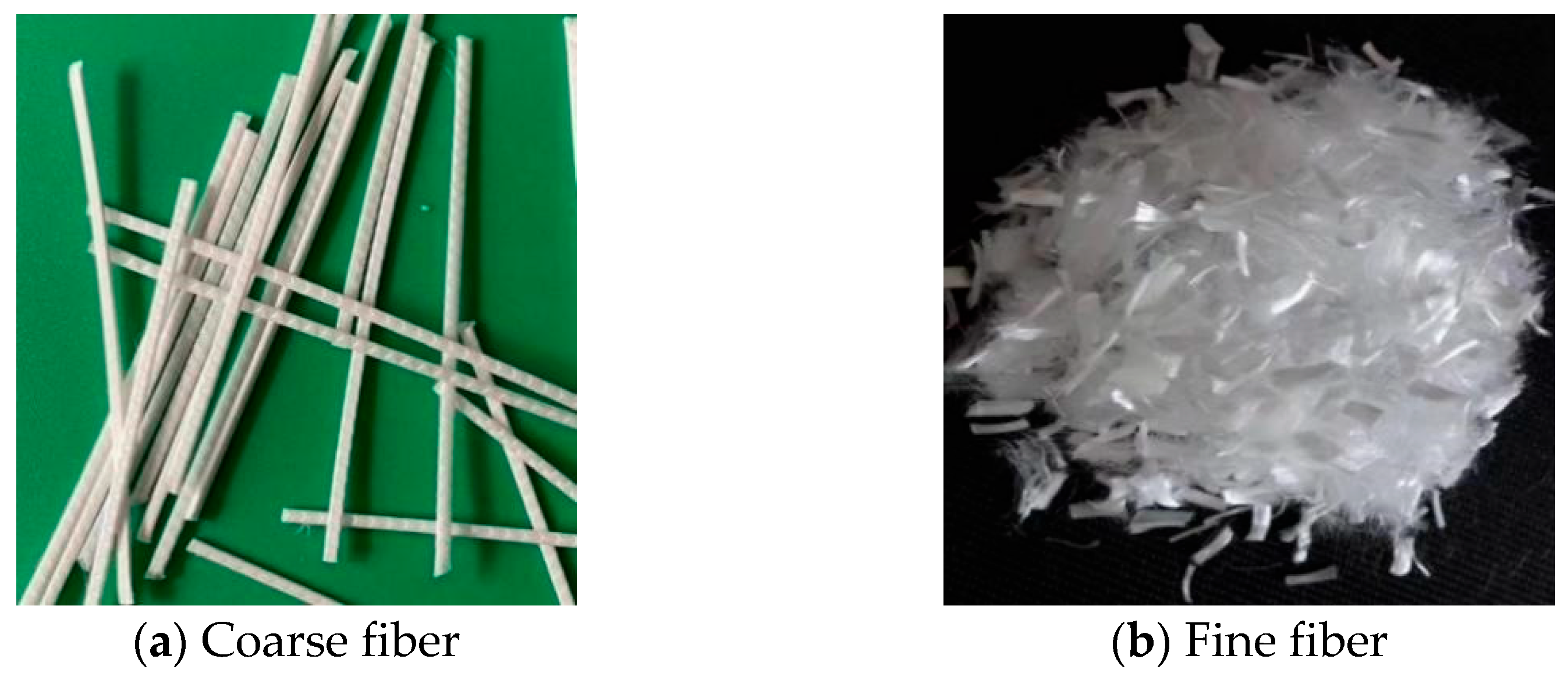
To produce polypropylene fiber-reinforced concrete for experimental purposes, raw materials such as cement, water, sand, aggregate, a water-reducing agent, and polypropylene fibers were used. These components were mixed in predetermined proportions and thoroughly stirred to form a homogeneous polypropylene fiber concrete. In this study, coarse polypropylene fibers with lengths of 30 mm and 50 mm were employed. The surfaces of these fibers are designed with wavy grooves to enhance their bond with the concrete matrix. The detailed performance parameters of both coarse and fine fibers are provided in Table 1, and Figure 3 illustrates the external morphology of the fibers.
The aggregates were classified into coarse aggregates and sand based on a particle size of 4.75 mm. The coarse aggregate was primarily crushed stone with a particle size ranging from 5 to 20 mm, an apparent density of 2690 kg/m3, and a bulk density of 1380 kg/m3. The sand used was natural dry river sand. It exhibited an apparent density of 2660 kg/m3 and a bulk density of 1520 kg/m3. Furthermore, its fineness modulus was 2.9, and the silt content was 1.7%.
In this study, ordinary Portland cement of the P.O.42.5R grade was selected as the test cement, with its specific performance parameters listed in Table 2. The cement exhibited a specific surface area of 350 m2/kg, which is conducive to accelerating the early hydration reaction, thereby enhancing early strength development. Experimental measurements indicated that the initial setting time is 95 min and the final setting time is 150 min, both of which comply with the requirements of the GB 175-2007 “General Portland Cement” standard [23] (initial setting time ≥ 45 min and final setting time ≤ 600 min). Furthermore, the compressive strength of the cement reaches 28.5 MPa at 3 days and increases to 49.3 MPa at 28 days, thus meeting the standard requirement for P.O.42.5R grade cement of attaining a compressive strength of not less than 42.5 MPa at 28 days.

2.2. Sample Design

In this study, reference was made to the “Technical Code for the Application of Fiber Reinforced Concrete” (JGJ_T 221-2010) [24] and other standards [25,26]. According to these guidelines, incorporating a certain quantity of synthetic fibers into ordinary concrete does not require an adjustment of the mix proportions. Moreover, report ACI544.1R-96 issued by the American Concrete Institute (ACI) recommends that the fiber volume fraction should be less than 2%. Related research has indicated that even under the 2% limitation, it is imperative to ensure effective vibration during the concrete mixing process [27]. Therefore, the volume fraction of coarse polypropylene fibers was set at three levels: 0.5%, 1%, and 1.5%, and two fiber lengths (30 mm and 50 mm) were considered. Given that fine fibers primarily act to control the formation of initial microcracks, the dosage and length of the fine fibers were maintained constant. A review of multiple studies on polypropylene fiber-reinforced concrete reveals that the dosage of fine polypropylene fibers is generally maintained below 2 kg/m3; excessive fiber content may result in an overly dense distribution within the concrete, insufficient cement paste encapsulation, and increased internal defects [28]. According to the “Technical Code for Fiber Reinforced Concrete Structures” [29] and relevant literature, the recommended dosage of fine fibers is 0.1%. In addition, if the fibers are too short, the anchorage provided by the fibers to the concrete matrix is inadequate for inhibiting crack propagation; conversely, excessively long fibers tend to agglomerate, which is detrimental to their strength. Consequently, the volume fraction of fine fibers was selected as 0.1% with a length of 12 mm.
In this study, the concrete specimens were categorized into seven groups based on variations in the volume fraction and length of coarse polypropylene fibers. The seventh group served as a blank control, consisting of plain concrete without fibers. To ensure consistency, all specimens were prepared using the same batch of materials. The mixing proportions, along with the characteristic values of the fiber dosage and fiber length for each experimental group, are presented in Table 3.
Based on variations in the volume fraction and length of the coarse polypropylene fibers, the experimental specimens were divided into seven groups. The age of all concrete specimens was 28 days. These specimens were used to assess four key mechanical properties of concrete: the compressive strength of concrete cubes, axial compressive stress–strain response, splitting tensile strength, and flexural strength. Three specimens were used for each test, amounting to a total of 12 specimens per group. The interface contact between fiber and concrete in the same group is regarded as the same [30]. The dimensions and quantities of the specimens used for the various tests are listed in Table 4.
This study employed a forced mixer to fabricate fiber-reinforced concrete specimens, aiming to achieve a uniform dispersion of polypropylene fibers within the concrete matrix and to fully exploit their reinforcing effect. During the mixing process, if agglomeration of fibers with varying diameters is observed, mixing should be immediately halted, and the clumped fibers should be mechanically loosened until a homogeneous fiber distribution is attained, and the mix meets the specified workability requirements. Subsequently, the mixture was cast into molds that were thoroughly cleaned and coated with oil, and vibratory compaction was applied to ensure concrete densification. After demolding and appropriate curing, the specimens were subjected to further mechanical property evaluations according to the standard [25,26] testing methods for concrete.

3. Cube Compressive Strength Test

3.1. Cube Compression Test Procedure

The compressive strength test was conducted using standard cube specimens with dimensions of 150 mm × 150 mm × 150 mm, with three specimens per group and seven groups. In accordance with the “Test Methods for Fiber Reinforced Concrete” (CECS:13-2009) [25], and after ensuring that both the specimens and the loading platen surfaces were clean, the side of the specimen corresponding to the casting form was selected as the loading surface. A YAW-3000 type compression testing machine was employed, with a strictly controlled loading rate of 0.5 MPa/s until failure, and the peak load was recorded.

3.2. Cube Compression Failure Pattern

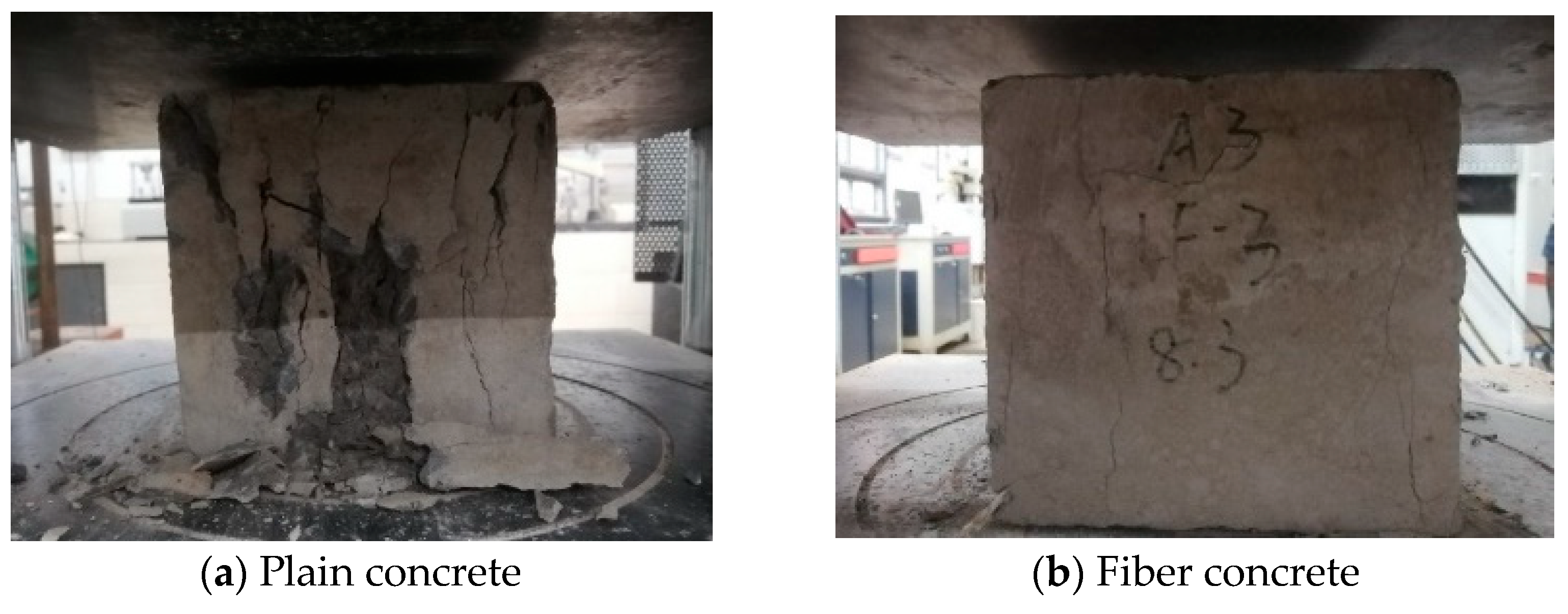
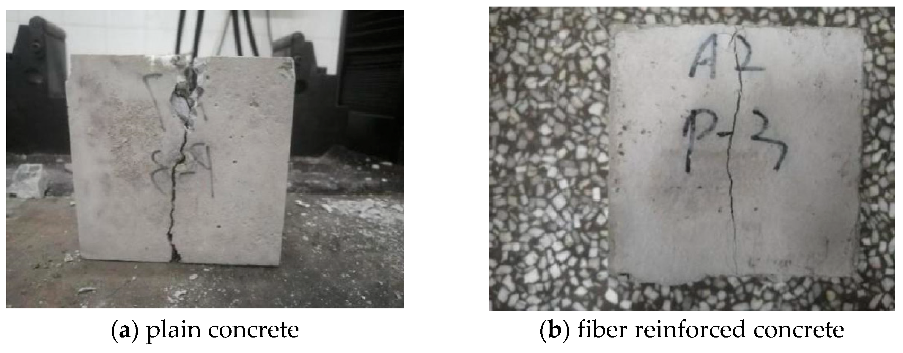
Figure 4 illustrates the failure modes of both the plain concrete and polypropylene fiber-reinforced concrete specimens under compressive loading. The plain concrete specimens (Figure 4a) developed several diagonal cracks in the early stages of loading; as the load increased, the crack widths progressively widened, eventually resulting in the detachment of large areas of concrete fragments and localized conical crushing, which is indicative of a brittle failure. In contrast, the concrete specimens incorporating polypropylene fibers (Figure 4b) generated distinct audible signals during loading due to fiber pull-out or rupture; the onset of cracking was notably delayed, and although the number of cracks increased with the applied load, the crack widths did not change significantly. The polypropylene fibers acted in a manner analogous to transverse reinforcement, effectively maintaining the overall integrity of the specimen and leading to a failure mode characterized by “cracking without complete disintegration.”
The differing failure modes are primarily attributed to the multi-level synergistic reinforcement provided by the fibers within the concrete. When the internal tensile stress is below the cracking threshold, the concrete primarily bears the tensile load; however, once micro-cracks initiate and propagate, a local loss of load-carrying capacity occurs, and the fibers bridging the cracks begin to contribute. The fine fibers, due to their relatively low modulus of elasticity and high quantity, effectively inhibit early-stage micro-crack propagation. As the crack widths increase, some fine fibers are progressively pulled out or fractured, while the macro fibers gradually assume the role of controlling further crack development. The composite incorporation of both coarse and fine polypropylene fibers effectively limits crack propagation at multiple stages and scales, thereby significantly enhancing the ductility and overall mechanical performance of the concrete.

3.3. Cube Compression Test Results

According to the requirements of the “Standard for Test Methods of Fiber Reinforced Concrete” (CECS: 13-2009) [25], the formula for calculating the compressive strength of concrete cubes is as follows:
f c u = F A
where fcu represents the compressive strength of the concrete cube (MPa), F represents the ultimate compression load (N), A—Compression area of specimen (mm2).
According to the “Test Methods for Fiber Reinforced Concrete” [25], this study adopts the mechanical testing method of plain concrete to evaluate fiber-reinforced concrete. The effective compressive strength is defined as the arithmetic mean of the compressive strengths of three specimens in the same test group (accurate to 0.1 MPa). The following exclusion criteria are applied: if the maximum or minimum value deviates from the median by more than 15%, the median value is taken as the final measured result; if both extreme values deviate from the median by over 15%, the test data for that group are considered invalid.
The specimens are divided into seven groups (A1–A7) based on the fiber content and fiber length, with three specimens per group; group A7 serves as the control group without fiber incorporation. Table 5 presents the compressive strengths of the cube specimens. It is noteworthy that, in the plain concrete group, specimen A7-3 exhibits a compressive strength of only 25.2 MPa, which is lower than that of the other specimens in the group. This discrepancy is primarily attributed to insufficient vibration during casting, leading to internal defects that markedly reduce the local strength.
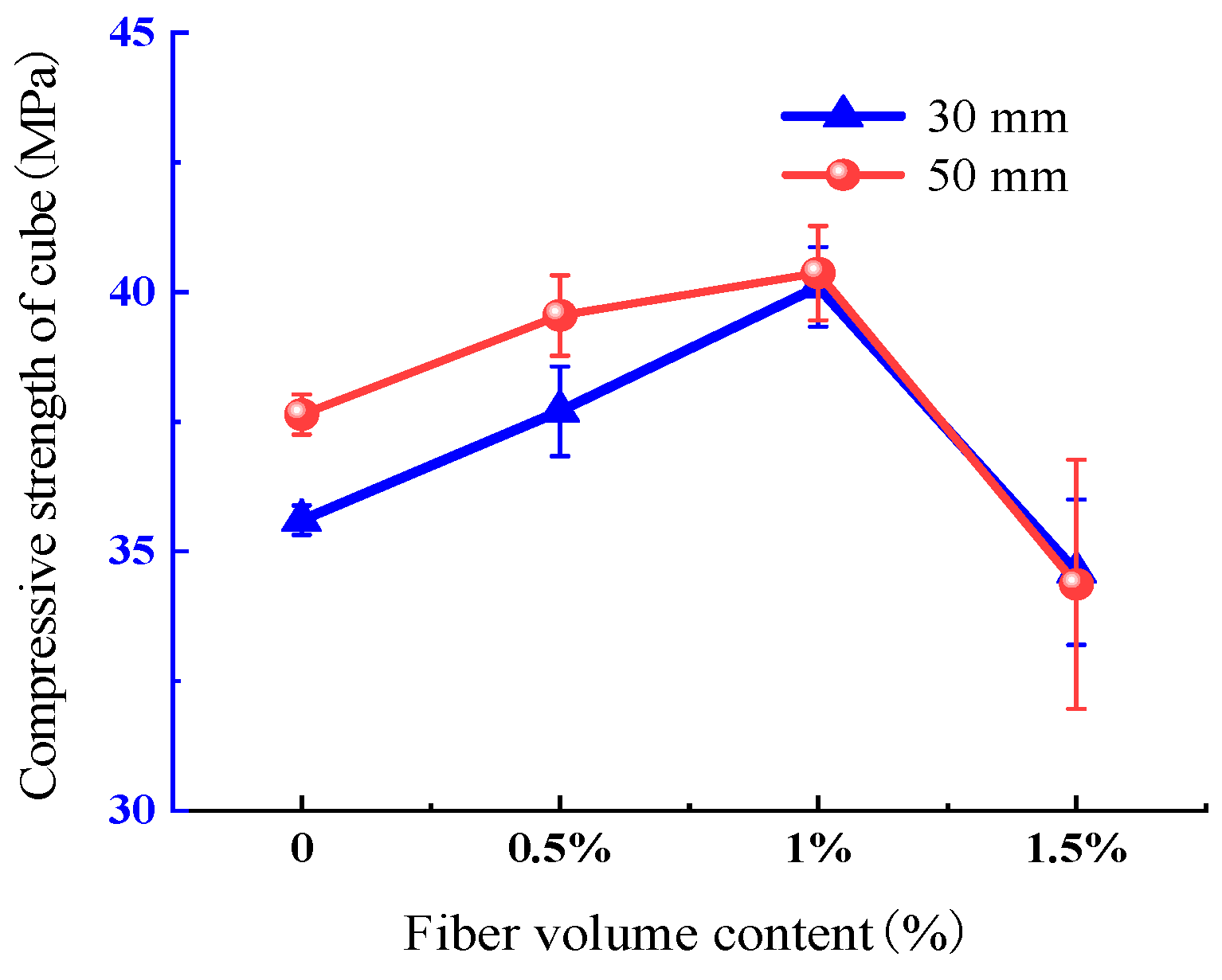
As illustrated in Figure 5, the compressive strength of the fiber-reinforced concrete cubes exhibited an initial increase, followed by a decrease with an increase in the polypropylene fiber content. Notably, group A3 (30 mm fiber, 1% fiber content) demonstrated an approximate 12.6% improvement in compressive strength. This outcome indicates that the inclusion of an appropriate amount of polypropylene fibers can establish a three-dimensional, randomly distributed network within the concrete, effectively acting as an intrinsic support system. Moreover, the rough-surfaced coarse polypropylene fibers bond well with the concrete, thereby delaying the initiation and propagation of cracks and consequently enhancing the overall compressive performance [31].
However, when the coarse polypropylene fiber content was increased from 1% to 1.5%, a decline in compressive strength was observed. This deterioration is attributed to the insufficient dispersion of an excessive amount of fibers, which tend to agglomerate. In addition, an overabundance of fibers compromises the encapsulation effect of concrete, leading to increased porosity and entrapped air bubbles that adversely affect compressive strength [32]. A comprehensive analysis of Table 5 and Figure 5 reveals that cube specimens in group A3 (30 mm fiber, 1% fiber content) exhibit a significant compressive strength enhancement of approximately 12.6%, whereas specimens in group A4 (50 mm fiber, 1% fiber content) achieve only about a 5.6% improvement. Furthermore, at a fiber content of 1.5 %, the detrimental effect on compressive strength is more pronounced for 50 mm fibers (group A6) than for 30 mm fibers (group A5). Therefore, with respect to the cube compressive strength of concrete, the optimal parameters for coarse polypropylene fibers were determined to be a fiber content of 1% and a fiber length of 30 mm, corresponding to the conditions of group A3, where the best performance is achieved.

4. Splitting Tensile Strength Test

4.1. Splitting Test Procedure

The splitting tensile test was conducted on non-standard cube specimens measuring 100 mm × 100 mm × 100 mm, with three specimens per group across seven groups, to evaluate the splitting tensile performance. In accordance with the “Test Methods for Fiber Reinforced Concrete” [25], the test was carried out using a CM-T5105 universal testing machine. Prior to testing, both the specimens and the contact surfaces of the testing machine were thoroughly cleaned, and the midline of the splitting surface was marked accurately. Steel shims and specimens were then precisely aligned with the center of the loading platen. The load was applied at a controlled rate of 0.05 MPa/s, and as the specimen approached failure, the machine throttle was adjusted until complete failure occurred.

4.2. Splitting Failure Pattern

For the plain concrete specimens, as the load increased, a primary crack initiated at the midsection of the specimen surface and rapidly propagated towards both the top and bottom. The crack width increased progressively with increasing load. Upon reaching the peak load, the specimen emitted a sudden impact sound and fractured along the crack into two unconnected parts, exhibiting a clear brittle-failure mode (Figure 6a).
By contrast, the failure mode of the fiber-reinforced concrete specimens exhibited notable improvements. With fiber incorporation, the crack width after reaching peak load was significantly reduced, and the specimen maintained a more integral structure, without complete separation into two disjointed parts. This indicates that the addition of fibers enhanced the deformation capacity of the concrete, effectively restraining crack propagation, and thereby improving the overall integrity and toughness of the concrete (Figure 6b).

4.3. Splitting Test Results

According to the “Test Methods for Fiber Reinforced Concrete” (CECS:13-2009) [25], the formula for calculating the splitting tensile strength of concrete cubes is as follows:
f t = 2 F p π A = 0.637 F p A
where ft represents the splitting tensile strength of concrete (MPa), Fp represents the splitting tensile limit load (N), and A represents the specimen splitting surface area (mm2).
To account for size effects, the present study employed non-standard specimens measuring 100 mm × 100 mm × 100 mm, with all results corrected using a dimensional conversion factor of 0.85 [26]. Detailed experimental results for each group are presented in Table 6.
The test results reveal that within the plain concrete group (A7), specimen A7-2 exhibited a splitting tensile strength of only 1.20 MPa, which is substantially lower than that of specimens A7-1 and A7-3. This discrepancy is primarily attributed to inadequate vibration control during the casting of the first batch of specimens, resulting in pronounced internal defects that compromised the tensile performance.
Data depicted in Figure 7 further demonstrates a significant positive effect of polypropylene fiber incorporation on the splitting tensile strength of concrete. This improvement is attributed to the bridging action of the fibers, which effectively share the tensile load when microcracks develop in the concrete matrix, thereby enhancing the overall tensile capacity. Overall, with an increasing fiber volume fraction, the splitting tensile strength initially increases and subsequently decreases; an excessive fiber content induces fiber balling and reduces mixing uniformity, consequently exacerbating the inherent defects in the concrete matrix and limiting the beneficial effects.
A comprehensive analysis of Table 6 and Figure 7 indicates that the optimal parameters for enhancing the splitting tensile strength are achieved with a polypropylene coarse fiber length of 30 mm and a dosage of 1% (group A3), which results in an improvement of up to 29.8%. In contrast, when using fibers of 50 mm length at the same dosage, the improvement is only 15.1%. Moreover, at a fiber content of 1.5%, the enhancement effect of 50 mm fibers is markedly inferior to that of 30 mm fibers. These results confirm that, with respect to the splitting tensile strength of concrete, the optimal parameters for polypropylene coarse fibers are a 1% dosage and a 30 mm fiber length (group A3).

5. Flexural Strength Test

5.1. Flexural Test Procedure

In this study, beam specimens measuring 100 × 100 × 400 mm were used, with three specimens per group and a total of seven groups, to evaluate the flexural performance of concrete. The test was conducted in accordance with the “Test Methods for Fiber Reinforced Concrete” [25], using a CM-T5105 universal testing machine with a span of 300 mm under a three-point bending setup. During the test, displacement-controlled loading was implemented: an initial loading rate of 0.1 mm/min was adopted until peak load was reached, after which the loading rate was increased to 0.5 mm/min until the deflection reached approximately 3 mm. Load–deflection data were automatically recorded by a computer throughout the test.

5.2. Flexural Failure Pattern

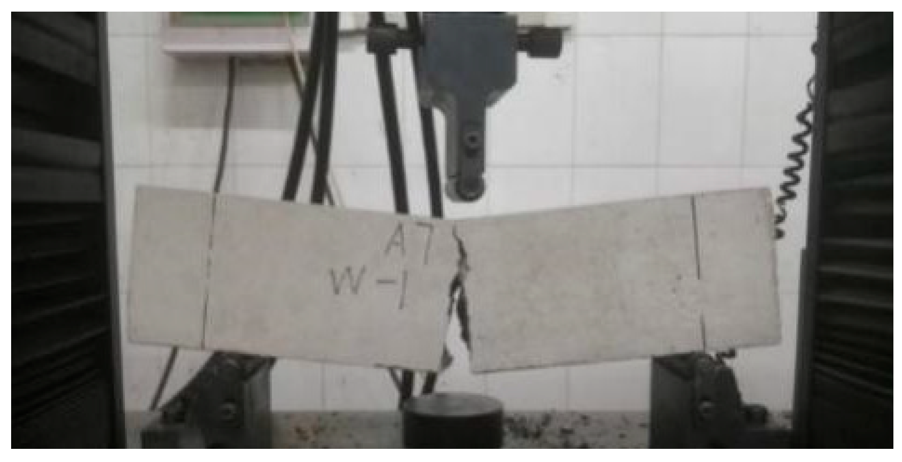
For plain concrete beams, the initial loading stage induced fine cracks at the bottom of the beam, which rapidly propagated along the cross-section; upon reaching the peak load, the mid-section of the beam suddenly fractured and the load sharply dropped, exhibiting a characteristic brittle failure (Figure 8).
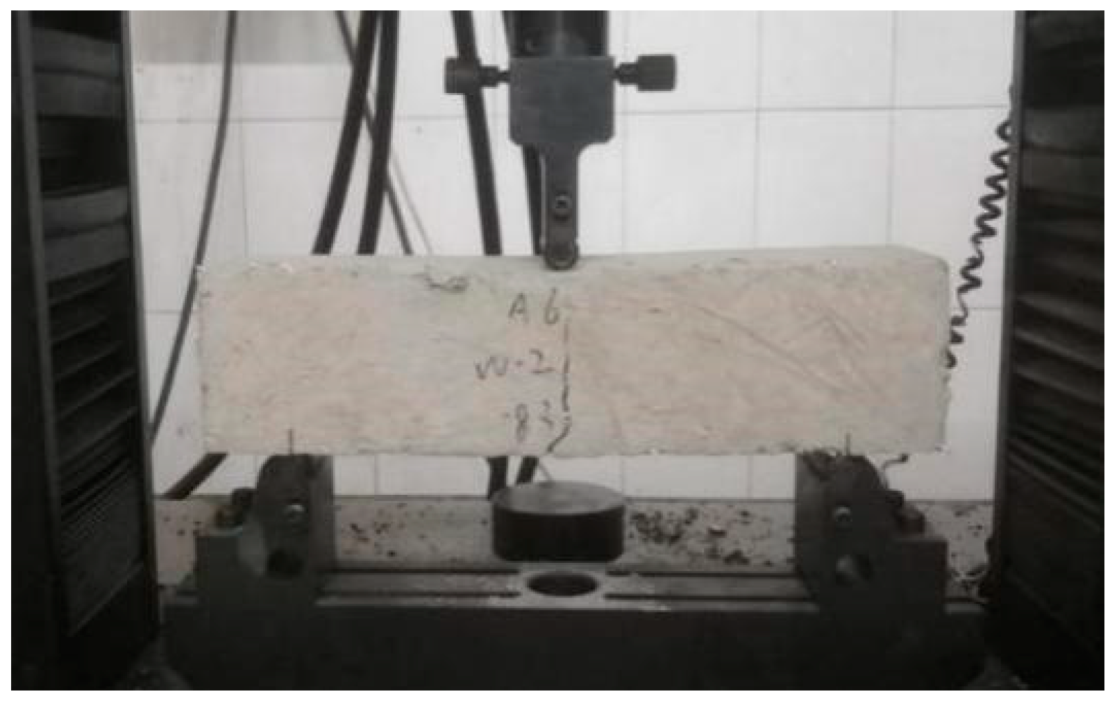
In contrast, the fiber-reinforced concrete beams incorporating polypropylene fibers did not exhibit any obvious cracking during the initial loading phase; cracks appeared abruptly near the peak load, accompanied by a low-frequency, dull sound. With continued loading, a fiber-bridging mechanism was observed along the crack, where fibers effectively carried and redistributed the tensile forces across the crack until they were eventually pulled out or fractured (Figure 9). Furthermore, the incorporation of fibers significantly delayed crack propagation; even after the specimen reached an approximate deflection of 3 mm and was subsequently replaced, the upper portion of the crack remained connected, and the overall integrity of the beam was maintained (Figure 10). This indicates that the inclusion of polypropylene fibers markedly enhanced the deformation capacity and toughness of the specimen, thereby providing an early warning before failure and extending the time available for a safe response.

5.3. Load-Deflection Curve

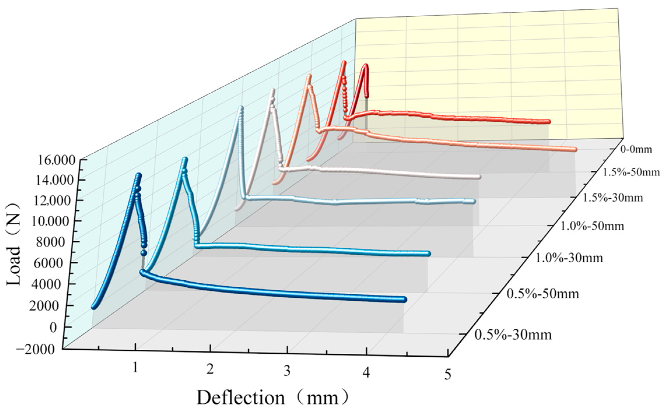
Analysis of the load–deflection curves for the various beam specimens (Figure 11) reveals that plain concrete beams exhibit a precipitous drop in load-carrying capacity after reaching the peak load, resulting in brittle failure. In contrast, beams with added polypropylene fibers, while showing a noticeable reduction in load-bearing capacity post-peak, retain a certain residual strength, with the latter portion of the curve tending to level off. As the fiber volume fraction increases, the residual strength gradually improves, whereas the fiber length has a negligible effect on residual strength. These results demonstrate that the incorporation of polypropylene fibers not only enhances the flexural strength of concrete but also significantly improves its toughness.

5.4. Flexural Test Results

The formula for calculating the bending strength of concrete under three-point bending loading is as follows:
f = 3 P l 2 b h 2
where f represents the flexural strength of concrete (MPa), P represents the flexural limit load (N), l represents the distance between supports (mm), l is set as 3h, b represents the specimen section width (mm), h represents the specimen section height (mm).
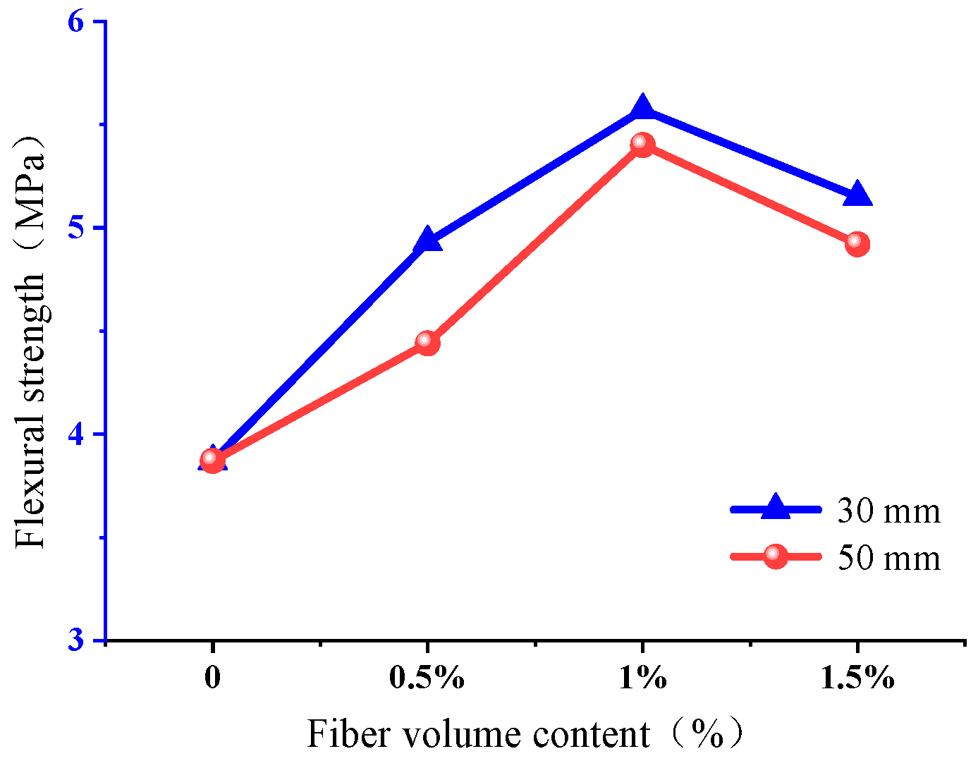
The effective flexural strength is determined using the same method as that for the effective compressive strength of cubes. In the present study, non-standard specimens were used for the flexural test, and the test results were corrected by applying a dimensional conversion factor of 0.85 [26]. The data presented in Table 7 directly reflect the deformation capacity of concrete members under the combined action of bending moments and tensile forces. As shown in Table 7, the incorporation of polypropylene fibers significantly enhanced the flexural strength of concrete, with a maximum increase of 44.5%.
Figure 12 illustrates that the trend of flexural strength variation with fiber volume content is consistent for different fiber lengths, with the optimum fiber content and length being 1% and 30 mm, respectively. Specifically, under the condition of 30 mm fiber length at 1% content, the flexural strength of the specimens increased by 44.5%, whereas for 50 mm fibers at 1% content (group A4), the increase was only 40%. Similarly, at a fiber content of 1.5%, the enhancement effect of 50 mm fibers was inferior to that of 30 mm fibers.
Combined analysis of Table 7 and Figure 12 shows that, under the same conditions of polypropylene coarse fiber length, increasing the fiber content from 1% to 1.5% (comparing A3 with A5 and A4 with A6) results in a somewhat reduced enhancement effect on flexural strength; however, the minimum strength increase still reaches 27.5%. This is because an excessive quantity of fibers diminishes the workability of concrete, complicates fiber dispersion, and increases the likelihood of clumping, thereby introducing additional defects into the matrix. Nonetheless, the positive effect of fibers on improving the flexural strength of concrete remains significant, even when fiber content is excessive, as the enhancement effect outweighs the detrimental impact on the matrix. In summary, based on the test results of cube compressive strength, splitting tensile strength, and flexural strength, the optimum parameters for polypropylene coarse fibers are determined to be 1% fiber content and 30 mm fiber length (group A3).

6. Axial Compressive Stress-Strain Curve Test

6.1. Test Procedure

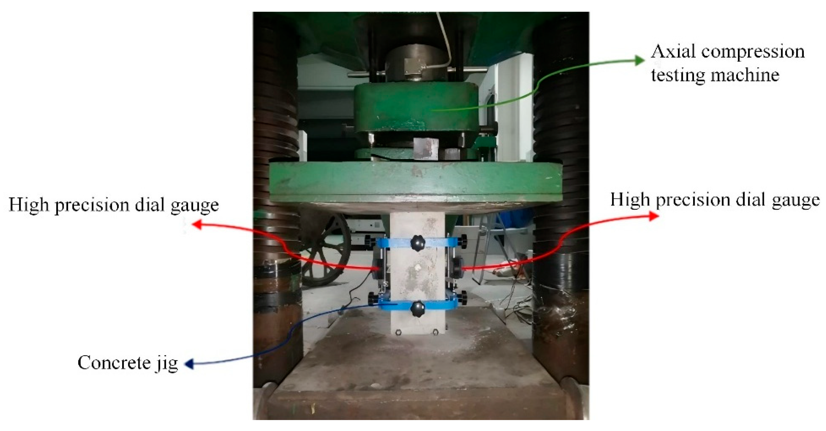
The experiment employed standard prismatic concrete specimens with dimensions of 150 mm × 150 mm × 300 mm, with three specimens per group for a total of seven groups. The test was conducted on a YAW-5000 electro-hydraulic servo pressure machine (500-ton capacity) under displacement-controlled uniaxial compression. As illustrated in Figure 13, the loading setup involved a thorough pre-treatment process—including cleaning the surfaces of both the specimen and the press platens—and precise centering of the specimen to ensure a purely axial loading state, thereby eliminating any eccentricity-induced errors. Axial deformation was measured in real time using electronic dial gauges with a 12.7 mm range, and the deformation was determined by averaging the readings from two gauges. During loading, as the specimen approached failure and the rate of deformation increased, a constant loading rate was maintained until complete failure occurred, enabling the capture of the entire stress–strain curve.

6.2. Failure Pattern Under Axial Compression

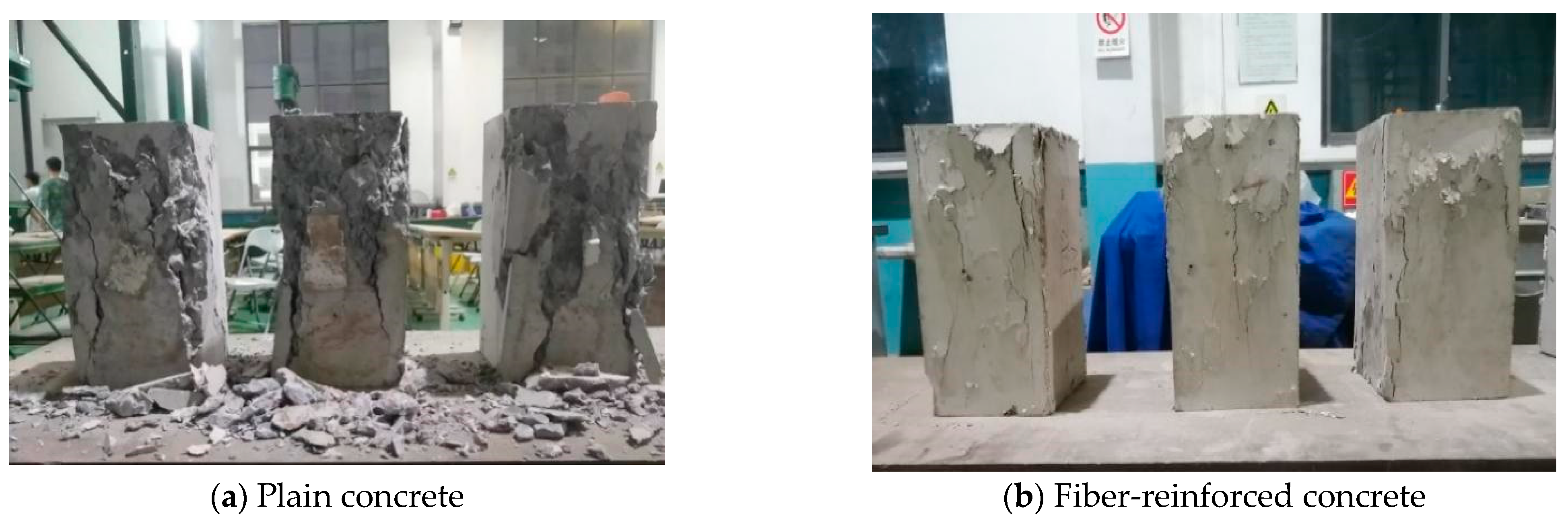
Figure 14 presents a comparison between plain concrete and polypropylene fiber-reinforced concrete specimens after axial compression. Under axial loading, the plain concrete specimens exhibited few cracks during the initial stage; however, once cracking initiated, the cracks rapidly expanded in both length and width, leading to sudden failure accompanied by the detachment of numerous fragments, thus displaying a distinctly brittle failure mode (Figure 14a). In contrast, the addition of polypropylene fibers resulted in the formation of multiple cracks without obvious detachment of concrete fragments. The fiber bridging mechanism maintained the overall integrity of the specimen after failure. During loading, the specimens emitted persistent cracking sounds, and the gradual progression of crack widths, along with the continuous generation of new cracks, indicated that the inclusion of polypropylene fibers significantly enhanced the ductility of the concrete (Figure 14b).
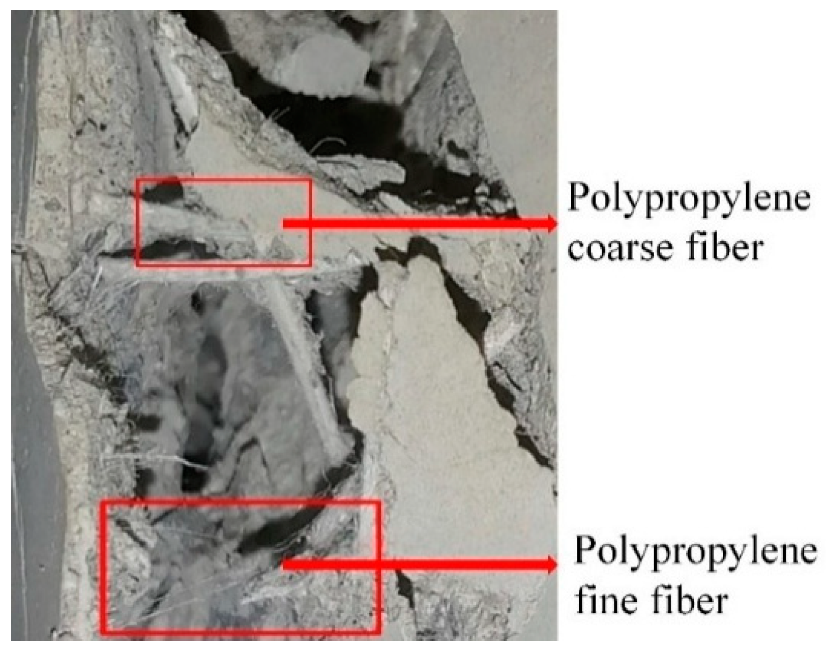
Post-failure observations of the fiber-reinforced concrete specimens (Figure 15) reveal that most of the coarse fibers were either pulled out or fractured during the loading process. Nevertheless, due to the high fiber content, a portion of the fibers continued to provide bridging action by linking the fractured concrete blocks on both sides of the cracks, thereby preventing widespread fragment detachment. Additionally, a substantial amount of fine fibers were observed to have fractured within the crack zones, as their relatively lower strength rendered them incapable of sustaining the increased stress once visible cracks developed, resulting in the loss of their load-bearing function.

6.3. Test Results

The average stress-strain data obtained from the axial compression tests are listed in Table 8. Notably, the fiber-reinforced concrete specimens displayed a more pronounced softening segment than the plain concrete group (A7), which clearly demonstrates the positive effect of incorporating polypropylene fibers on the ductility and toughness of the concrete. Based on the experimental data, group A3—with a fiber volume fraction of 1% and fiber length of 30 mm—achieved the highest peak strength of 32.66 MPa.
A comprehensive analysis of the stress–strain curves and corresponding mechanical parameters indicates that the concrete strength initially increases and subsequently decreases with a gradual increase in polypropylene fiber content. In particular, groups A5 and A6, which incorporated 1.5% coarse polypropylene fibers, exhibited a slight reduction in strength. This phenomenon can be attributed to the poor distribution of excessive fiber content within the concrete matrix, which leads to reduced matrix compactness and the introduction of additional micro-defects, ultimately impeding the enhancement of the overall load-bearing capacity of the concrete.

6.4. Fitting of the Axial Compressive Stress–Strain Curve

The uniaxial compressive stress–strain curve of concrete is a vital experimental foundation for structural design and nonlinear numerical analysis and has attracted extensive attention from researchers worldwide. Existing studies primarily adopt dimensionless segmented expressions to describe the stress–strain behavior of both single-and hybrid fiber-reinforced concrete. Among these, the constitutive model proposed by Guo [33] has been widely applied due to its simplicity in terms of parameters and clear physical significance. Based on this model, the present study develops a segmented curve model for concrete reinforced with both coarse and fine polypropylene fibers, which is expressed as
y = a x + ( 3 2 a ) x 2 + ( a 2 ) x 3 0 x 1 y = x b ( x 1 ) 2 + x x   >   1
where y = σ / f c , x = ε / ε c , σ denotes the axial compressive stress, f c represents the uniaxial compressive strength, ε is the compressive strain, and ε c is the strain corresponding to the peak compressive strength; a and b control the shapes of the ascending and descending segments of the curve, respectively.
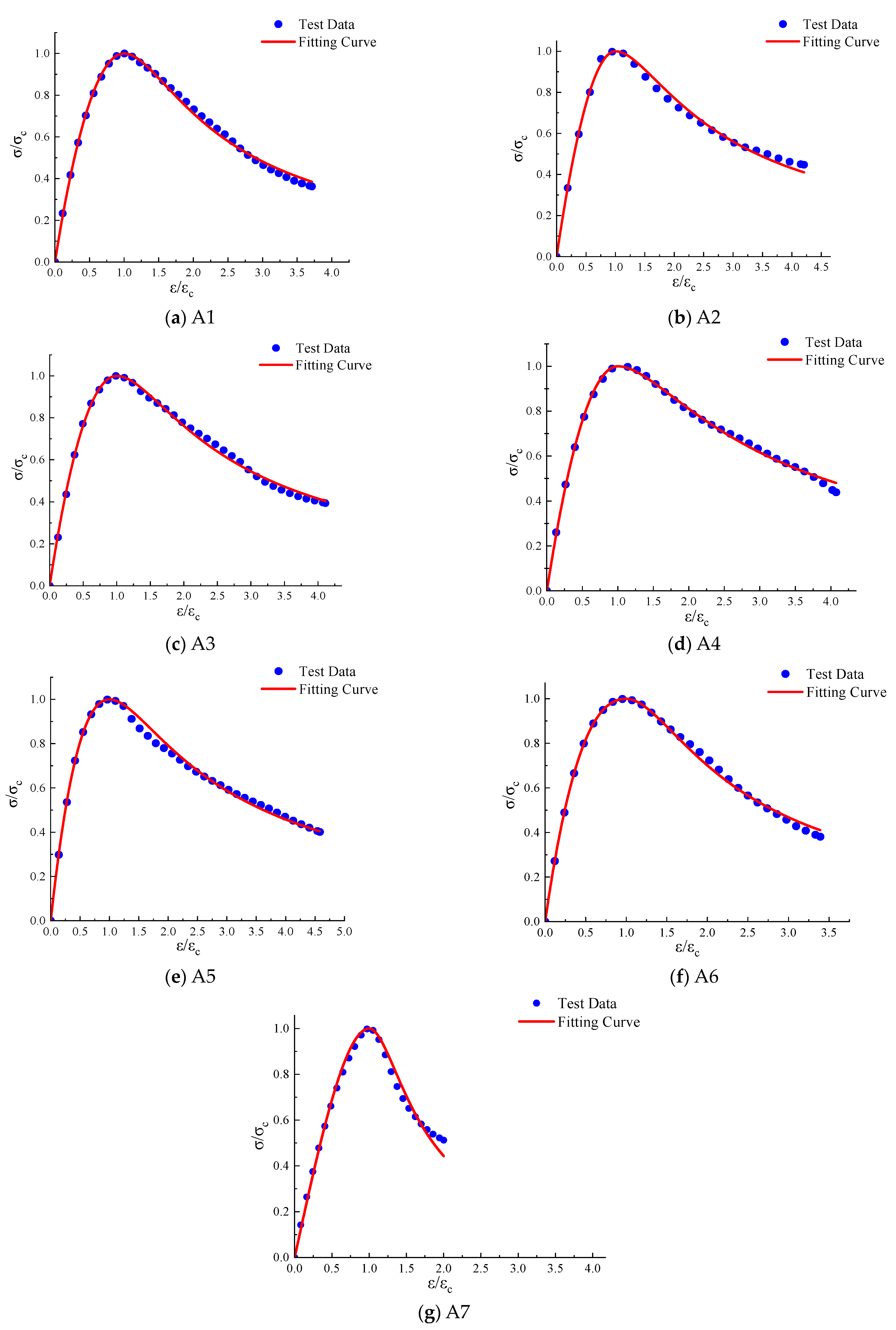
The least-squares method is a common fitting technique [34]. Based on seven sets of experimental data, the least-squares method was employed to fit the segmented curve model, yielding stress–strain curves that were in excellent agreement with the experimental results (Figure 16).
Based on the comparison of the fitted curves in Figure 16 with the experimental data, a very good agreement is observed, which accurately reflects the constitutive behavior of the concrete in the present tests. The specific numerical values of shape parameters a and b for each group of curves are listed in Table 9.
To elucidate the relationship between the shape parameters a and b and the concrete’s axial compressive strength as well as fiber characteristics (including the coarse polypropylene fiber volume fraction and aspect ratio), the least-squares method was used to derive the following empirical formulas:
a = 5.21325 + 5.3839 f 0.07352 + 1.170615 λ f
b = 1.4588 + 1.82517 f 0.09542 + 2.81356 λ f 2.78533 1.9545 λ f
where f denotes the axial compressive strength, λf is the fiber characteristic parameter λ f = ρ f l f / d f , ρ f is the volume fraction of coarse polypropylene fiber; l f / d f is the aspect ratio of coarse polypropylene fiber. when λ f = 0 , a = 1.50728, b = 2.51253.
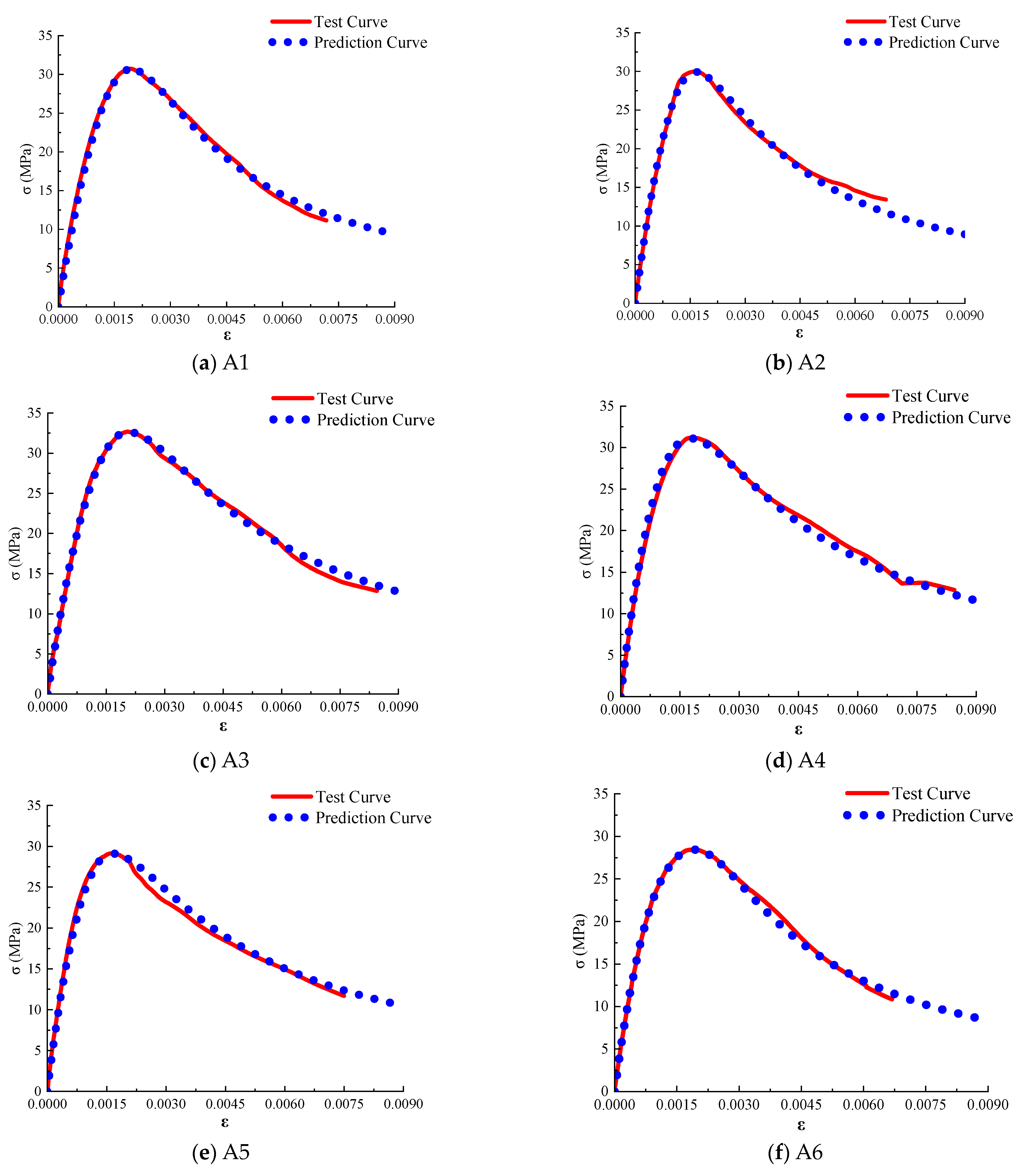
To validate the applicability of the proposed fitting formulas and segmented curve model, the parameters calculated from the empirical formulas were substituted into the model, and the resulting curves were compared with the experimental curves (Figure 17). The results indicate that the proposed model and parameter fitting formulas can accurately capture the constitutive behavior of polypropylene fiber-reinforced concrete, thereby providing a robust experimental basis for finite element analyses of concrete reinforced with both coarse and fine polypropylene fibers.

7. Conclusions

This study designed seven test groups by systematically varying the content and length of polypropylene coarse fibers to investigate the mechanical properties of polypropylene fiber-reinforced concrete. The main conclusions are as follows:
(1)
Under uniaxial loading, plain concrete specimens exhibited typical brittle failure characterized by rapid crack propagation and significant spalling. In contrast, fiber-reinforced concrete specimens maintain integrity due to the crack-bridging effect of the fibers, which effectively controls the crack width and results in a “cracked but not crushed” failure mode, thereby achieving notable crack resistance and toughness enhancement.
(2)
The experimental results indicate that the mechanical properties of concrete initially increase and then decrease with increasing fiber content. Within the range studied, when the coarse fiber content was 1% and the fiber length was 30 mm, the compressive strength, splitting tensile strength, and flexural strength of the specimens increased by 12.6%, 29.8%, and 44.5%, and each index of concrete specimen reached its best. Respectively, compared to plain concrete. However, when the fiber content was increased to 1.5%, agglomeration phenomena occurred, leading to a marked deterioration in the overall performance.
(3)
In flexural tests, plain concrete specimens exhibited sudden brittle fracture, whereas fiber-reinforced specimens were able to maintain structural continuity after the appearance of mid-span cracks due to the bridging action of the fibers. The residual strength increased with fiber content, which clearly demonstrates the significant improvement in ductility and crack resistance imparted by the fibers, thereby verifying the potential application of polypropylene fiber-reinforced concrete in sandwich wall panels and similar structures.
(4)
Based on existing segmented stress–strain equations for concrete, a model for the axial compression curve of polypropylene fiber-reinforced concrete was developed. Using the least-squares method, the relationship between the shape parameter, axial compressive strength, and fiber characteristic value was established. The model predictions, when compared with experimental data, showed excellent agreement, indicating that the proposed shape parameter formulation and corresponding curve model can accurately predict the axial stress–strain behavior of polypropylene fiber-reinforced concrete.
The present study provides a preliminary reference for the performance of polypropylene fiber-reinforced concrete; however, avenues for further research remain. It should be noted that the study has certain limitations due to experimental conditions and time constraints. The relatively small sample size may have affected the statistical robustness of the results. Future work should pursue a more comprehensive mechanical evaluation by employing a larger sample size and incorporating tests such as tensile strength. Furthermore, an in-depth micro-structural investigation, particularly focusing on the fiber-matrix interface and change in pore structure, would be instrumental in revealing the underlying principles of its performance enhancement.

Author Contributions

Methodology, P.L., M.H., Y.S. and X.T.; formal analysis, M.H.; investigation, X.T.; resources, Y.S.; data curation, Y.K. and G.X.; writing—original draft preparation, M.H.; writing—review and editing, P.L.; visualization, Y.S. and Y.K.; supervision, P.L. and G.X. All authors have read and agreed to the published version of the manuscript.

Funding

This research was funded by the Shandong province technology-based small and medium-sized enterprises innovation capability enhancement project (No. 2023TSGC0188).

Conflicts of Interest

Author Yingying Shang is employed by the Zhejiang Jinggong Steel Building Group Co., Ltd. The remaining authors declare that the research was conducted in the absence of any commercial or financial relationships that could be construed as a potential conflict of interest.

References

  1. Song, S.; Chen, G.; Li, P.; Zhao, Y.; Zhang, T.; Bao, H.; Xiong, G.; Zhao, X. Investigation into wind resistance performance of cable-stiffened spherical latticed shells. J. Constr. Steel Res. 2025, 229, 109507. [Google Scholar] [CrossRef]
  2. Liu, G.; Gu, T.; Xu, P.; Hong, J.; Shrestha, A.; Martek, I. A production line–based carbon emission assessment model for prefabricated components in China. J. Clean. Prod. 2019, 212, 123–134. [Google Scholar] [CrossRef]
  3. General Office of the State Council of China. Guiding Opinions on Vigorously Developing Prefabricated Buildings; [State Council Document No. 71, 2016]; General Office of the State Council: Beijing, China, 2016. [Google Scholar]
  4. Mustafaraj, E.; Yardim, Y.; Corradi, M.; Perenchio, W.R. Polypropylene as a retrofitting material for shear walls. Materials 2020, 13, 2503. [Google Scholar] [CrossRef]
  5. Salmon, D.; Einea, A. Partially composite sandwich panel deflections. J. Struct. Eng. 1995, 121, 778–783. [Google Scholar] [CrossRef]
  6. Joseph, J.; Prabakar, J. Insulated precast concrete sandwich panels under punching and flexural actions. PCI J. 2019, 64, 68–79. [Google Scholar] [CrossRef]
  7. Ashraf, A.; Nibras, M. Reactive powder concrete sandwich panels with mechanical connection approach. In Proceedings of the 2018 International Conference on Advance of Sustainable Engineering and its Application, Wasit, Iraq, 14–15 March 2018; pp. 121–125. [Google Scholar]
  8. Benayoune, A.; Aziz, A.; Samad, A.; Trikha, D.; Ali, A.A.A. Structural behaviour of eccentrically loaded precast sandwich panels. Constr. Build. Mater. 2005, 20, 647–656. [Google Scholar] [CrossRef]
  9. Benayoune, A.; Samad, A.A.; Trikha, D.; Ali, A.A.; Ellinna, S. Flexural behaviour of precast concrete sandwich composite panels: Experimental and theoretical investigations. Constr. Build. Mater. 2008, 22, 580–592. [Google Scholar] [CrossRef]
  10. Li, X.W. Experimental study on basic and early mechanical properties of different fiber-reinforced concrete. J. Anhui Univ. Sci. Technol. 2017, 32, 45–52. [Google Scholar]
  11. Yang, X.; Liang, N.; Hu, Y.; Feng, R. An experimental study of shear resistance for multisize polypropylene fiber concrete beams. Int. J. Concr. Struct. Mater. 2021, 15, 52. [Google Scholar] [CrossRef]
  12. Hameed, R.; Turatsinze, A.; Duprat, F.; Sellier, A. A study on the reinforced fibrous concrete elements subjected to uniaxial tensile loading. KSCE J. Civ. Eng. 2010, 14, 547–556. [Google Scholar] [CrossRef]
  13. Kim, D.J.; Park, S.H.; Ryu, G.S.; Koh, K.T. Comparative flexural behavior of hybrid ultra high performance fiber reinforced concrete with different macro fibers. Constr. Build. Mater. 2011, 25, 4144–4152. [Google Scholar] [CrossRef]
  14. Dawood, E.T.; Ramli, M. High strength characteristics of cement mortar reinforced with hybrid fibres. Constr. Build. Mater. 2011, 25, 2240–2247. [Google Scholar] [CrossRef]
  15. Dawood, E.T.; Ramli, M. Durability of high strength flowing concrete with hybrid fibres. Constr. Build. Mater. 2012, 35, 521–530. [Google Scholar] [CrossRef]
  16. Ahmad, H.; Sheikh, M.N.S.; Hadi, M. Behaviour of GFRP bar-reinforced hollow-core polypropylene fiber and glass fiber concrete columns under axial compression. J. Build. Eng. 2021, 44, 103245. [Google Scholar] [CrossRef]
  17. Cui, K.; Xu, L.; Li, X.; Hu, X.; Huang, L.; Deng, F.; Chi, Y. Fatigue life analysis of polypropylene fiber reinforced concrete under axial constant-amplitude cyclic compression. J. Clean. Prod. 2021, 319, 128610. [Google Scholar] [CrossRef]
  18. Zhou, X.; Zeng, Y.; Chen, P.; Jiao, Z.; Zheng, W. Mechanical properties of basalt and polypropylene fibre-reinforced alkali-activated slag concrete. Constr. Build. Mater. 2021, 269, 121284. [Google Scholar] [CrossRef]
  19. Liu, J.; Jia, Y.; Wang, J. Experimental study on mechanical and durability properties of glass and polypropylene fiber reinforced concrete. Fibers Polym. 2019, 20, 1928–1936. [Google Scholar] [CrossRef]
  20. Wang, H.; He, X.; Zhou, M.; Wei, B.; Wu, W.; Zhou, G.; He, J. A study on the tensile fracture behavior of polypropylene fiber reinforced concrete based on a microscale model. Constr. Build. Mater. 2024, 417, 135291. [Google Scholar] [CrossRef]
  21. Song, P.S.; Hwang, S.; Sheu, B.C. Strength properties of nylon- and polypropylene-fiber-reinforced concretes. Cem. Concr. Res. 2005, 35, 1546–1550. [Google Scholar] [CrossRef]
  22. Kakooei, S.; Akil, H.M.; Jamshidi, M.; Soroushian, P. The effects of polypropylene fibers on the properties of reinforced concrete structures. Constr. Build. Mater. 2012, 30, 814–825. [Google Scholar] [CrossRef]
  23. Ministry of Industry and Information Technology of China. GB 175-2023; Common Portland Cement. China Standards Press: Beijing, China, 2023.
  24. Ministry of Housing and Urban-Rural Development of China. JGJ/T 221-2010; Technical Specification for Application of Fiber Reinforced Concrete. China Architecture & Building Press: Beijing, China, 2011.
  25. China Association for Engineering Construction Standardization. CECS 13:2009; Standard Test Methods for Fiber Reinforced Concrete. China Planning Press: Beijing, China, 2009.
  26. Ministry of Housing and Urban-Rural Development of the People’s Republic of China. GB/T 50081-2019; Standard for Test Methods of Concrete Physical Andmechanical Properties. China Planning Press: Beijing, China, 2009.
  27. Zhou, L.J.; Ren, X.D.; Li, J. Experimental technique for uniaxial tensile dynamic constitutive relation of concrete. Struct. Eng. 2016, 32, 163–168. [Google Scholar]
  28. Zhang, Y. Study on Mechanical Properties and Damage Failure Modes of Polypropylene Fiber Reinforced Concrete. Master’s Thesis, Xi’an University of Technology, Xi’an, China, 2019. [Google Scholar]
  29. China Association for Engineering Construction Standardization. CECS 38:2004; Technical Specification for Fiber Reinforced Concrete Structures. China Planning Press: Beijing, China, 2004.
  30. Li, L.; Li, X.Z.; Wang, B.Y.; Tao, J.C.; Shi, K. A review on interfacial bonding behavior between fiber and concrete. J. Build. Eng. 2025, 105, 112455. [Google Scholar] [CrossRef]
  31. Lan, F. Study on the Influence of Coarse Polypropylene-Basalt Fiber on Bearing Capacity of Concrete Pipes. Master’s Thesis, Chongqing University: Chongqing, China, 2021. [Google Scholar]
  32. Hao, Y.F.; Yang, G.Z.; Liang, K.K. Development of fly ash and slag based high-strength alkali-activated foam concrete. Cem. Concr. Compos. 2022, 128, 104447. [Google Scholar] [CrossRef]
  33. Guo, Z.H. Strength and Constitutive Relationship of Concrete: Principles and Applications; China Architecture & Building Press: Beijing, China, 2004. [Google Scholar]
  34. Liu, Y.; Chen, B.; Liu, X.; Liu, C.; Miao, J.; Weng, C.; Luo, Y. Experimental study on bond performance between corroded reinforcement and basalt-polypropylene fiber reinforced concrete after high temperature. Constr. Build. Mater. 2025, 474, 140944. [Google Scholar] [CrossRef]
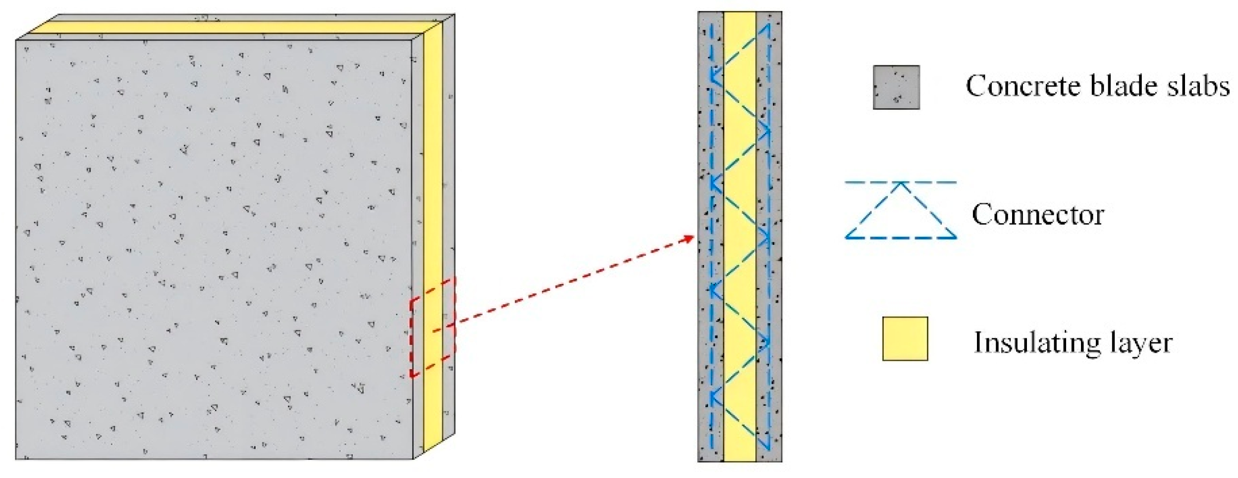
Figure 1. Three-dimensional diagram of the sandwich wall panel.
Buildings 15 02971 g001
Figure 2. Concrete sandwich wall panel physical drawing.
Buildings 15 02971 g002
Figure 3. Appearance of polypropylene fiber.
Buildings 15 02971 g003
Figure 4. Compression failure of concrete.
Buildings 15 02971 g004
Figure 5. Effect of fiber length and volume content on compressive strength of cube.
Buildings 15 02971 g005
Figure 6. Splitting tensile failure of concrete.
Buildings 15 02971 g006
Figure 7. Effect of fiber length and volume content on splitting tensile strength.
Buildings 15 02971 g007
Figure 8. Failure of plain concrete beam.
Buildings 15 02971 g008
Figure 9. Failure of fiber concrete beam.
Buildings 15 02971 g009
Figure 10. Polypropylene fiber bridging.
Buildings 15 02971 g010
Figure 11. Load-deflection curve.
Buildings 15 02971 g011
Figure 12. The influence of fiber length and volume content on flexural strength.
Buildings 15 02971 g012
Figure 13. The loading setup.
Buildings 15 02971 g013
Figure 14. Comparison of failure forms of prismatic specimens.
Buildings 15 02971 g014
Figure 15. Internal fiber condition of fiber concrete after crushing.
Buildings 15 02971 g015
Figure 16. Uniaxial compressive stress–strain curve.
Buildings 15 02971 g016
Figure 17. The prediction curve was compared with the axial compressive stress-strain curve.
Buildings 15 02971 g017
Table 1. Performance index of polypropylene coarse and fine fibers.
Fiber TypeLength/mmDiameter/μmDensity/(g·cm−3)Fusing Point/°CTensile Strength/MPaModulus of Elasticity/GPaElongation at Break/%Alkali
Resistance/%
Coarse fiber30/5010000.91174627.9106.398.9
Fine fiber12270.911686255.22299
Table 2. Performance index of cement.
Specific Surface Area/(m2·kg−1)Setting Time/minCompressive Strength/MPaFlexural Strength/MPa
Initial SetFinal Set3d28d3d28d
3509515028.549.35.67.9
Table 3. Concrete mix ratio of each group /(kg·m−3).
Experimental GroupWaterCementSandGravelCoarse and Fine Fiber Content Volume Rate/(%)Coarse and Fine Fibers
Length/(mm)
124045355311240.5% + 0.1%30 + 12
224045355311240.5% + 0.1%50 + 12
324045355311241% + 0.1%30 + 12
424045355311241% + 0.1%50 + 12
524045355311241.5% + 0.1%30 + 12
624045355311241.5% + 0.1%50 + 12
72404535531124
Table 4. Size and quantity of each group of specimens.
TestSpecimen Size/(mm)Sample Curing MethodMaintenance
Completed or Not
Cube Compressive Strength150 × 150 × 1503Natural curingYes
Axial Compressive Stress–Strain Curve150 × 150 × 3003Natural curingYes
Splitting Tensile Strength100 × 100 × 1003Natural curingYes
Flexural Strength100 × 100 × 4003Natural curingYes
Table 5. Compressive strength test results of the cubes.
Sample NumberFiber Content and Length
(%-mm)
Compressive Strength
(MPa)
Effective Compressive Strength
(MPa)
Strength Growth Rate
(%)
A1-10.5%-30 mm37.537.75.9
A1-238.6
A1-336.9
A2-10.5%-50 mm37.637.03.9
A2-236.5
A2-336.8
A3-11.0%-30 mm40.040.112.6
A3-239.0
A3-340.5
A4-11.0%-50 mm38.037.65.6
A4-237.9
A4-336.8
A5-11.5%-30 mm33.234.6−2.8
A5-234.5
A5-336.0
A6-11.5%-50 mm31.633.2−6.7
A6-233.0
A6-335.1
A7-1——35.635.6
A7-236.0
A7-325.2 *
* Indicates data excluded from analysis due to insufficient vibration during casting, which caused internal defects and abnormally low compressive strength.
Table 6. Splitting tensile strength test results.
Sample NumberFiber Content and Length
(%-mm)
Tensile Strength
(MPa)
Effective Tensile Strength
(MPa)
Strength Growth Rate
(%)
A1-10.5%-30 mm2.162.2015.2
A1-22.27
A1-32.16
A2-10.5%-50 mm2.002.046.8
A2-22.07
A2-32.47
A3-11.0%-30 mm2.712.4829.8
A3-22.35
A3-32.37
A4-11.0%-50 mm2.232.2015.2
A4-22.21
A4-32.15
A5-11.5%-30 mm2.302.2417.3
A5-22.09
A5-32.34
A6-11.5%-50 mm1.981.941.6
A6-21.71
A6-32.14
A7-1——1.911.91
A7-21.20
A7-32.19
Table 7. Bending strength test results.
Sample NumberFiber Content and Length
(%-mm)
Bending Strength
(MPa)
Effective Bending Strength
(MPa)
Strength Growth Rate
(%)
A1-10.5%-30 mm3.193.39
A1-23.6827.9
A1-33.29
A2-10.5%-50 mm3.153.05
A2-22.8015.1
A2-33.21
A3-11.0%-30 mm3.943.83
A3-23.8744.5
A3-33.68
A4-11.0%-50 mm3.653.71
A4-23.6340
A4-33.85
A5-11.5%-30 mm3.433.54
A5-23.4233.6
A5-33.76
A6-11.5%-50 mm3.233.38
A6-23.6027.5
A6-33.31
A7-1——2.752.65
A7-22.84
A7-32.37
Table 8. Compressive strength test results.
Sample NumberFiber Content and Length
(%-mm)
Compressive Strength
(MPa)
Strain at Peak StressStrength Growth Rate
(%)
A10.5%-30 mm30.740.00198.1
A20.5%-50 mm29.990.00165.3
A31.0%-30 mm32.660.00214.7
A41.0%-50 mm31.150.00189.3
A51.5%-30 mm29.150.00172.4
A61.5%-50 mm28.440.0019−0.1
A7——28.480.0013
Table 9. Specific values of shape parameters a and b for each group of curves.
A1A2A3A4A5A6A7
a2.101071.946142.113962.056962.458622.533791.50728
b0.806740.588380.627170.467480.526810.852102.51253
Disclaimer/Publisher’s Note: The statements, opinions and data contained in all publications are solely those of the individual author(s) and contributor(s) and not of MDPI and/or the editor(s). MDPI and/or the editor(s) disclaim responsibility for any injury to people or property resulting from any ideas, methods, instructions or products referred to in the content.