Comparison of Hot Cracking Susceptibility of TIG and Laser Beam Welded Alloy 718 by Varestraint Testing


 ,
,
Abstract
:1. Introduction
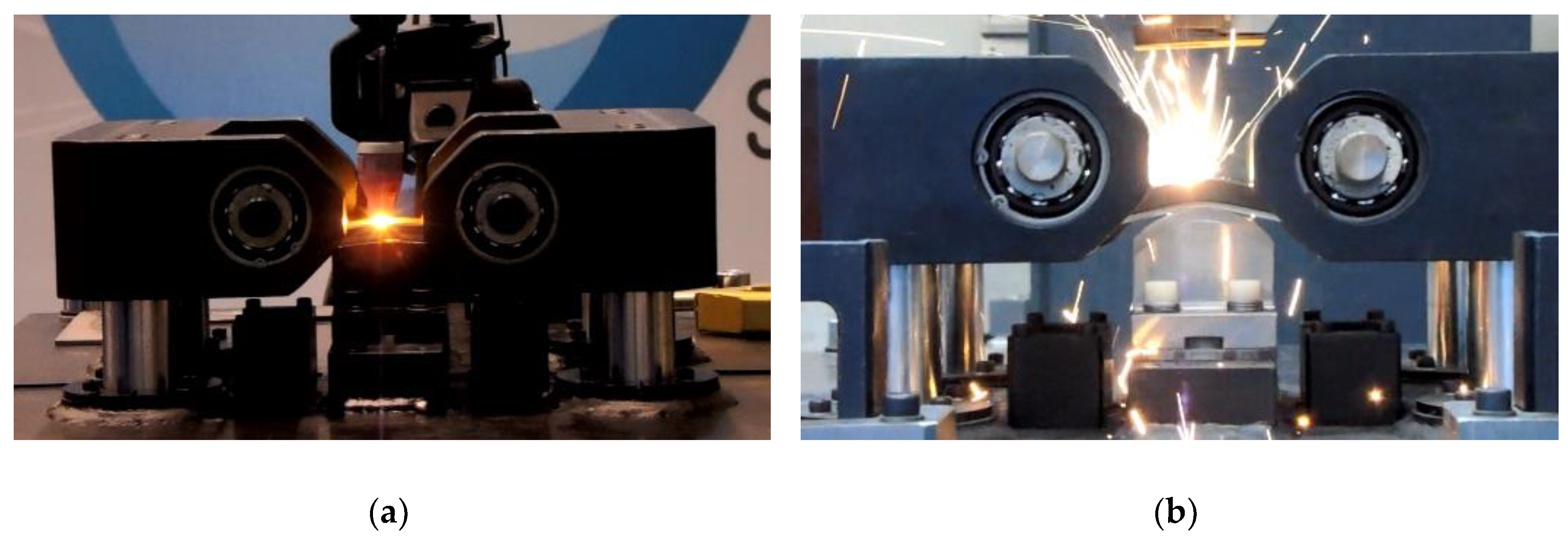
2. Materials and Methods
3. Results
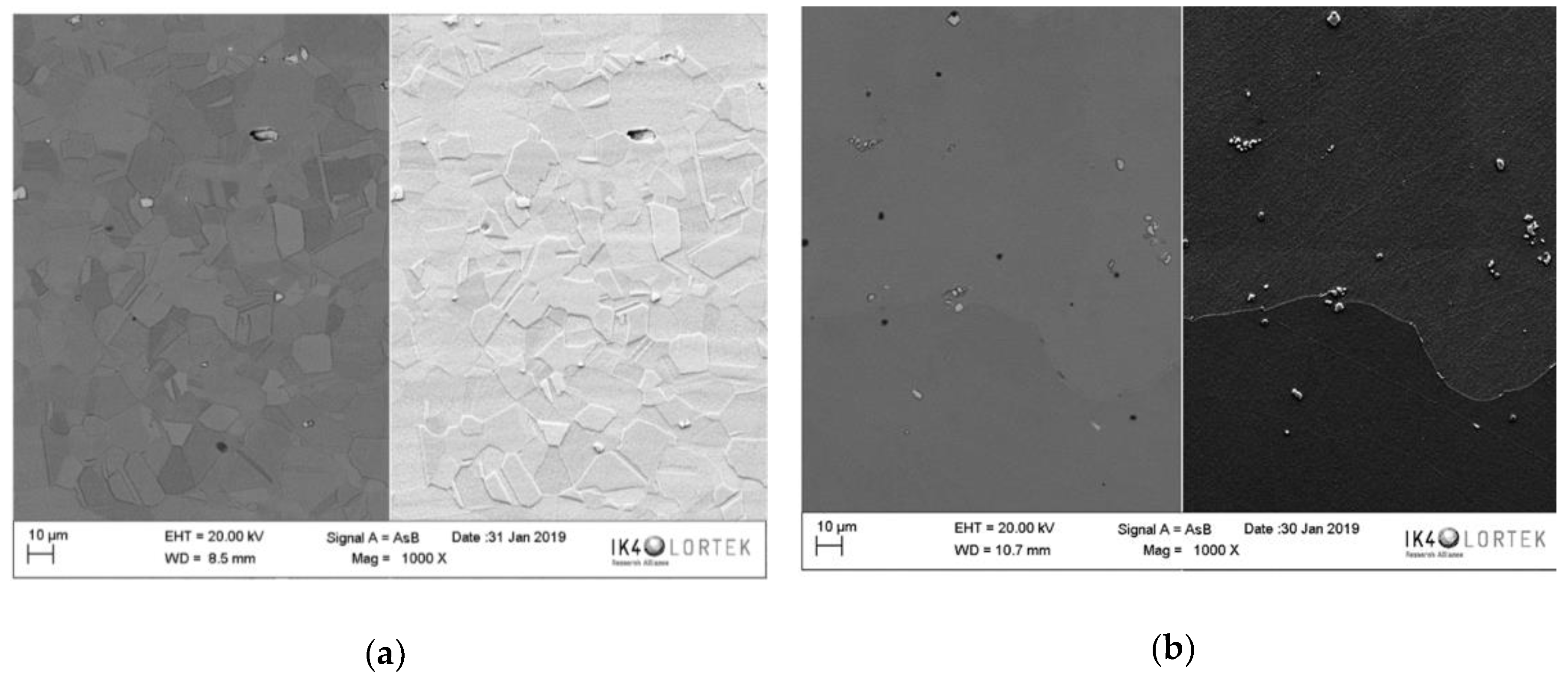
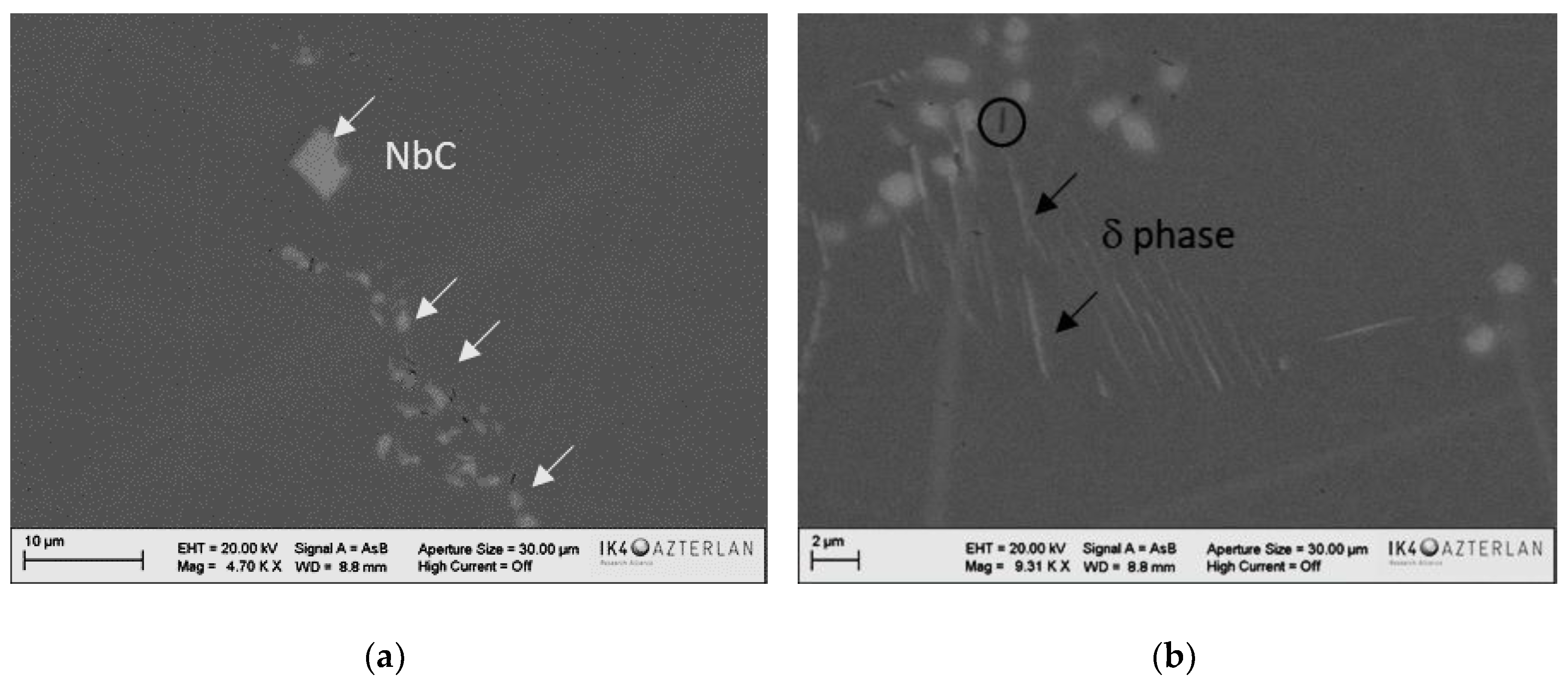
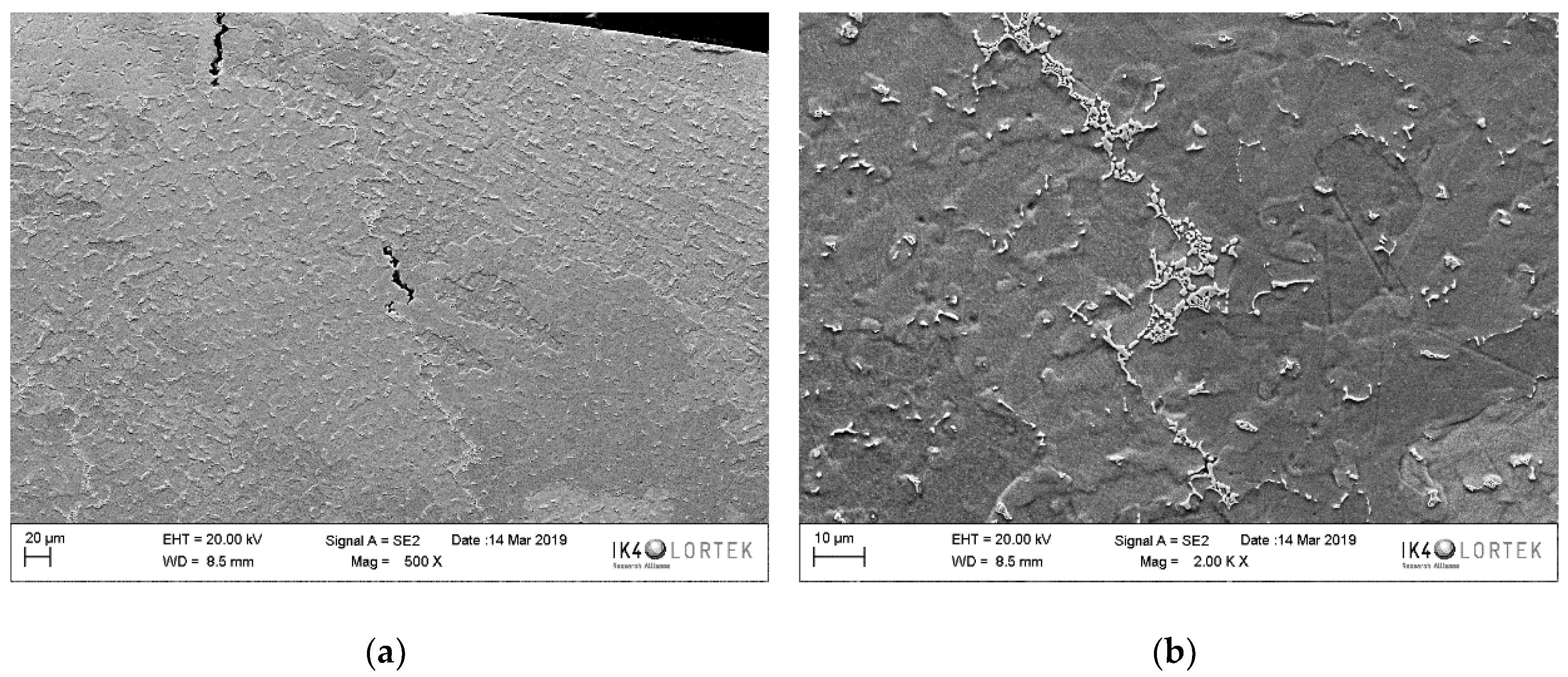
3.1. Base Material Microstructure
3.2. Welding Parameters and Microstructure
3.2.1. TIG Welding
3.2.2. LBW
3.3. Varestraint Test Results
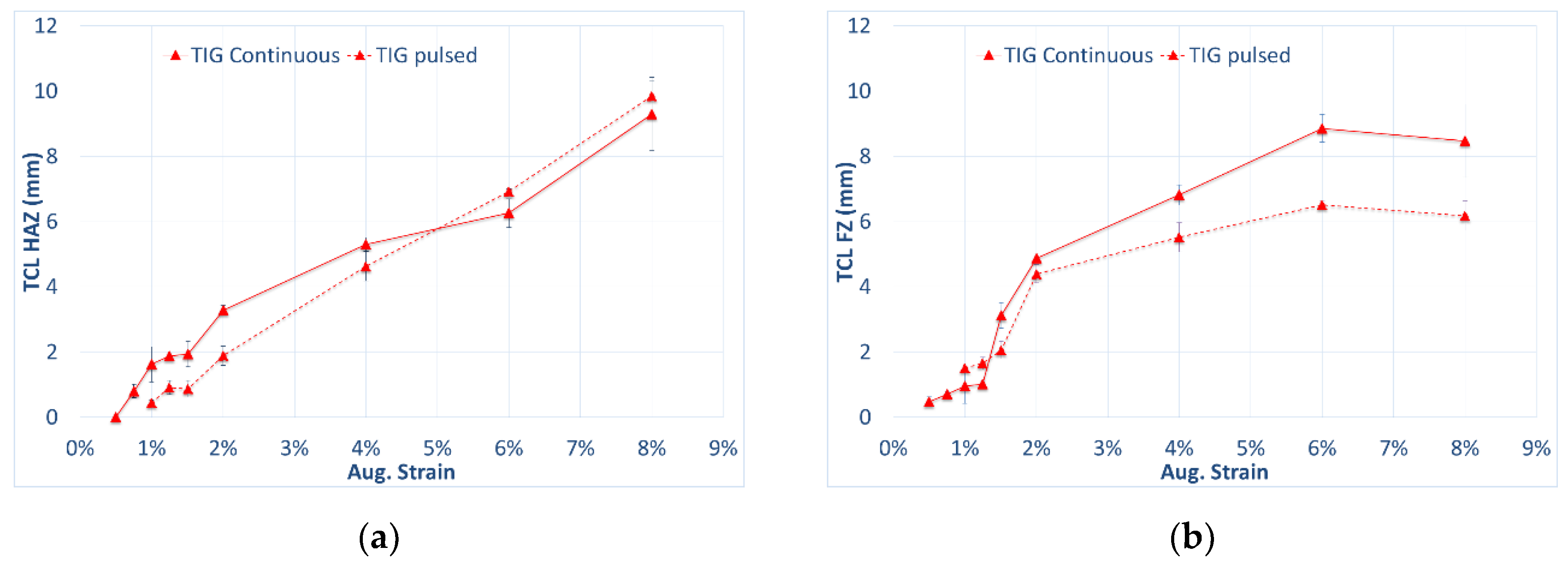
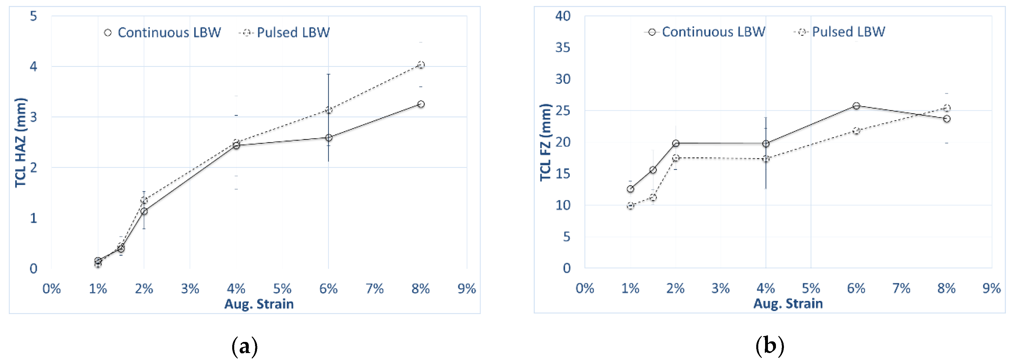
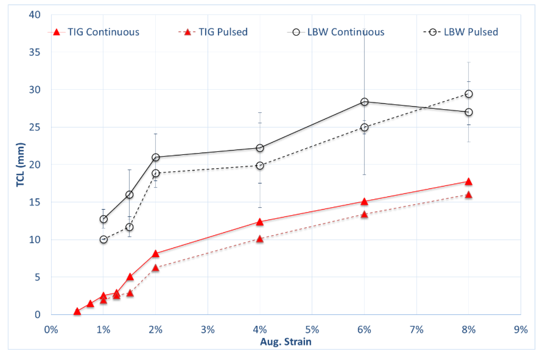
3.3.1. Influence of Welding Parameters on Cracking Susceptibility of Wrought Alloy 718
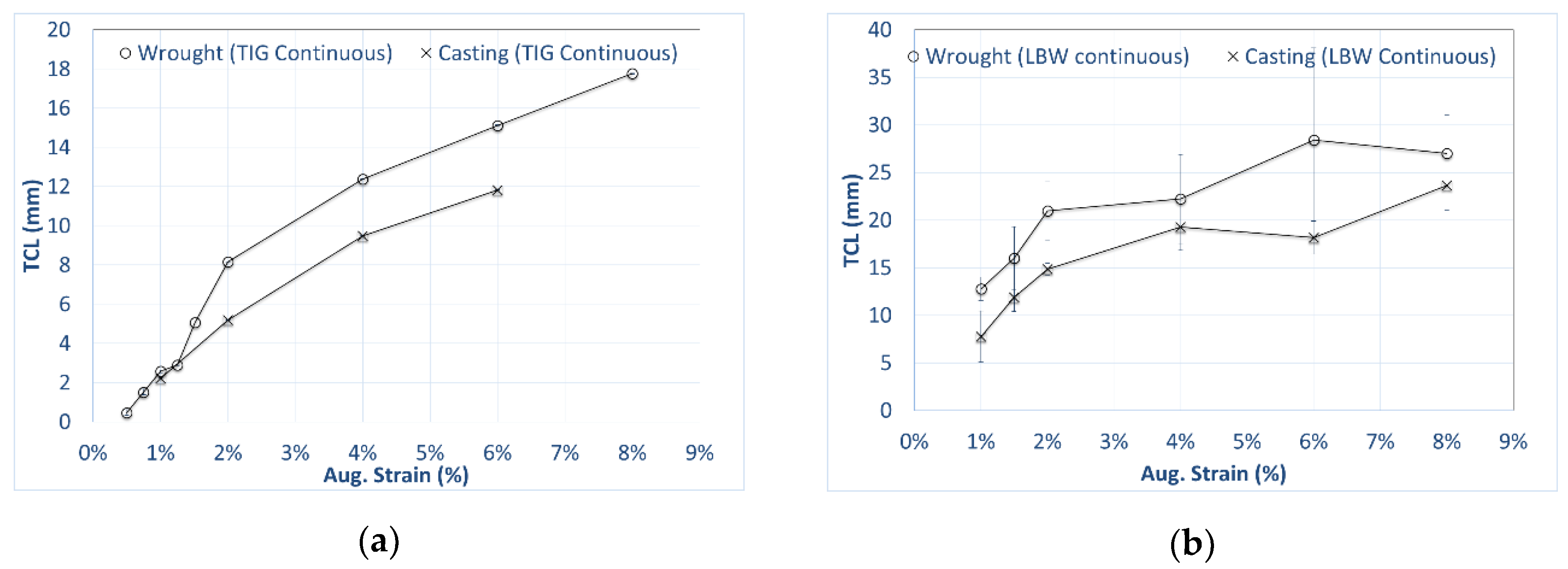
3.3.2. Comparison between Wrought and Investment Casting Samples
4. Discussion
5. Conclusions
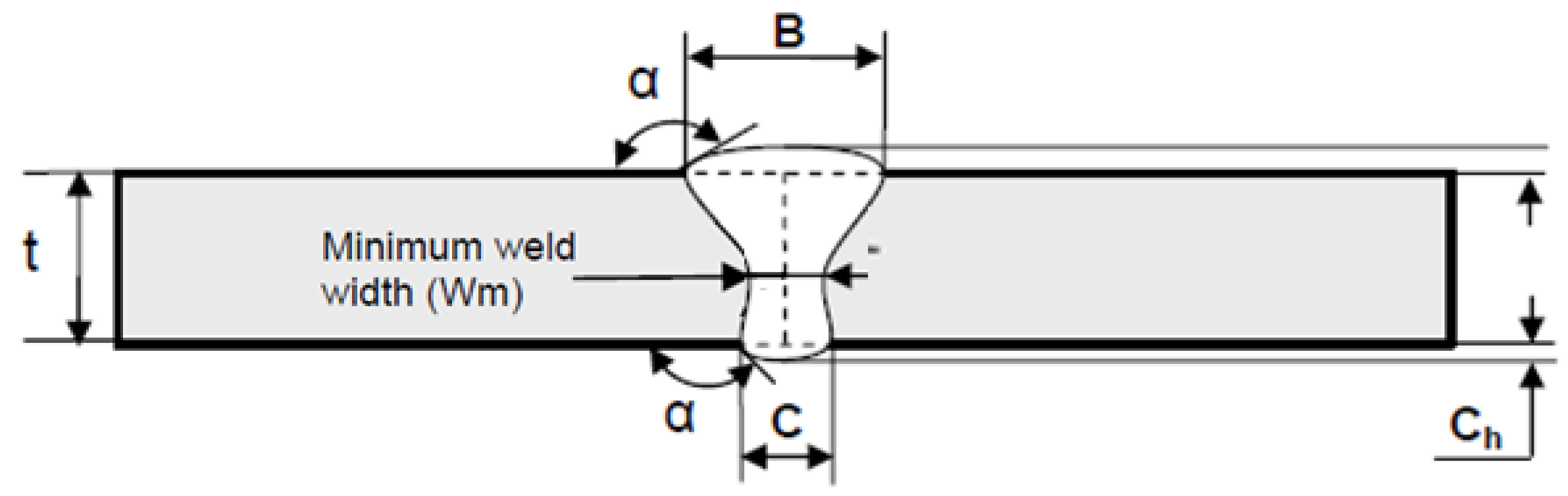
- The hot cracking susceptibility of alloy 718 determined by the Varestraint test and resulting from applying LBW was higher than that for TIG welding conditions. Welding parameters were thoroughly selected to get sound welds and meet industrial welding quality criteria, particularly in terms of minimum weld width (Wm), underfill, overhang and porosity.
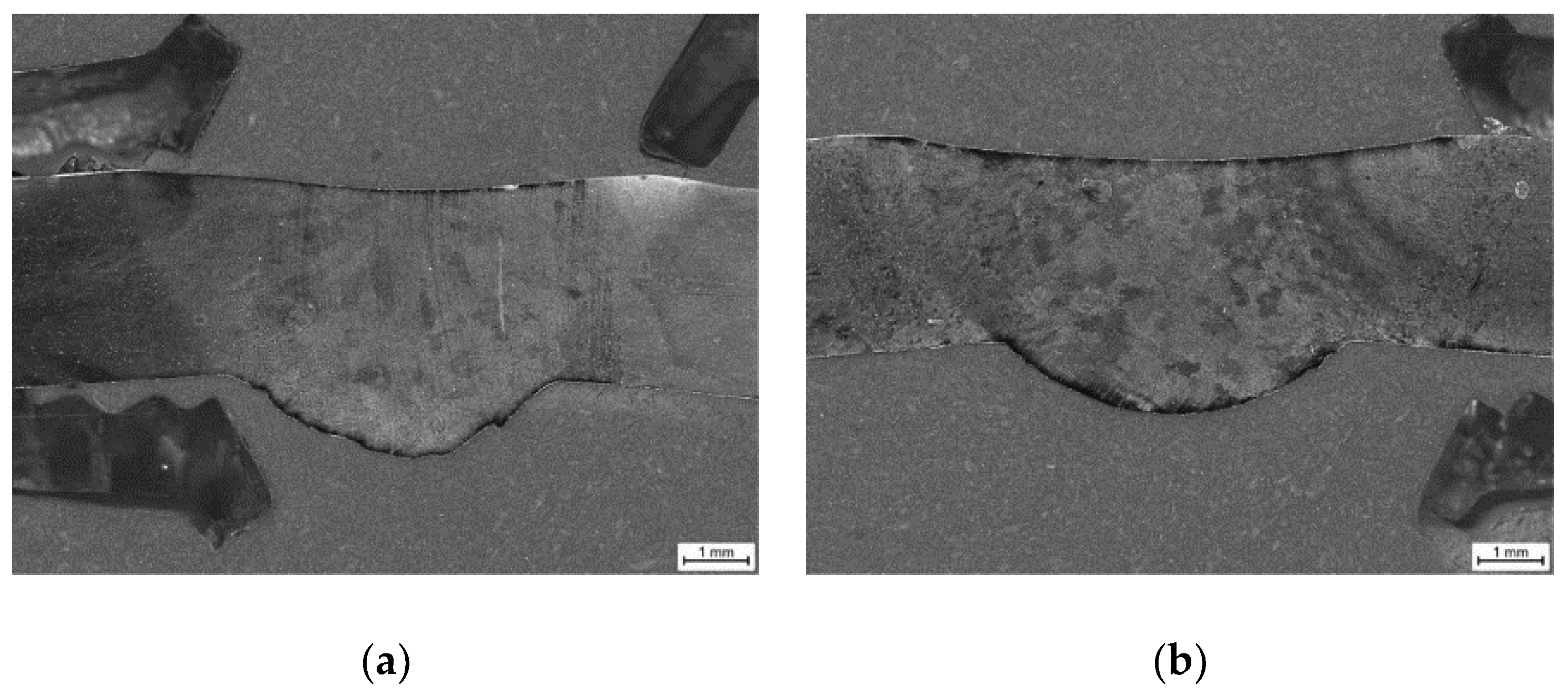
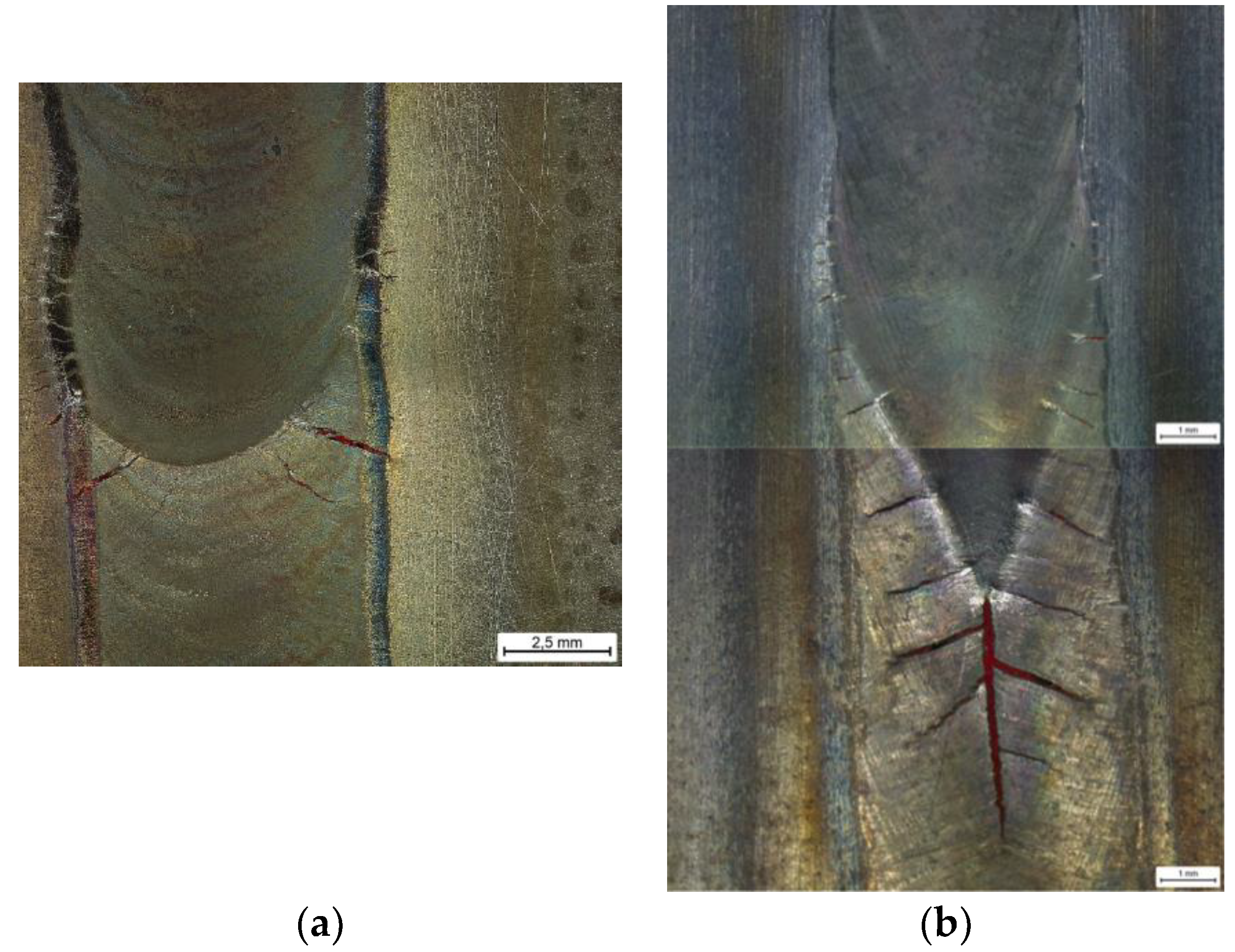
- LBW enhanced hot cracking tendency was directly related to a different solidification pattern (enlarged V-shape) that promotes long center line FZ solidification cracking and fish-bone like cracks.
- Minor effect of material source (wrought versus investment casting), grain size and pulsation was observed. Investment casting with much coarser average grain size (around 1 mm) shown comparatively better cracking behavior than wrought material (grain size below 30 microns). Both base materials had a microstructure free of Laves phases and Nb segregations, but they were observed in the interdendritic boundaries of the welds creating a network and decorating the path of FZ cracks.
Author Contributions
Funding
Acknowledgments
Conflicts of Interest
References
- Lippold, J.C.; Kiser, S.D.; DuPont, J.N. Welding Metallurgy and Weldability of Nickel-Base Alloys; John Wiley & Sons, Inc.: Hoboken, NJ, USA, 2009. [Google Scholar]
- Schirra, J.J.; Caless, R.H.; Hatala, R.W. The effect of Laves phase on the mechanical properties of wrought and cast+ HIP Inconel 718. Superalloys 1991, 718, 375–388. [Google Scholar] [CrossRef]
- Thompson, E.G. Hot Cracking Studies of Alloy 718 Weld HAZ. Weld. J. 1969, 48, 70s–79s. [Google Scholar]
- Thompson, G.R.; Genculu, S. Microstructural Evolution in the HAZ of Inconel 718 and Correlation with the Hot Ductility Test. Weld. Res. Suppl. 1983, 62, 337–345. [Google Scholar]
- Duvall, D.S.; Owczarski, W.A. Further Heat-Affected- Zone Studies in Heat Resistant Nickel Alloys. Weld. J. 1967, 46, 423–432. [Google Scholar]
- Gordine, J. Some Problems in Welding Inconel 718. Weld. Res. Suppl. 1971, 50, 480–484. [Google Scholar]
- Thompson, R.G.; Dobbs, J.R.; Mayo, D.E. The Effect of Heat Treatment on Microfissuring in Alloy 718. Weld. J. 1986, 65, 299–304. [Google Scholar]
- Vincent, R. Precipitation around welds in the nickel-base superalloy, Inconel 718. Acta Metall. 1985, 33, 1205–1216. [Google Scholar] [CrossRef]
- Guo, H.; Chaturvedi, M.; Richards, N. Effect of boron concentration and grain size on weld heat affected zone microfissuring in Inconel 718 base superalloys. Sci. Technol. Weld. Join. 1999, 4, 257–264. [Google Scholar] [CrossRef]
- Woo, I.; Nishimoto, K.; Tanaka, K.; Shirai, M. Effect of grain size on heat affected zone cracking susceptibility.Study of weldability of Inconel 718 cast alloy (2nd Report). Weld. Int. 2000, 14, 514–522. [Google Scholar] [CrossRef]
- Radhakrishnan, B.; Thompson, R.G. Modeling of microstructure evolution in the weld HAZ. Met. Sci. Join. 1991, 31–40. [Google Scholar]
- Guo, H.; Chaturvedi, M.C.; Richards, N.L. Effect of nature of grain boundaries on intergranular liquation during weld thermal cycling of nickel base alloy. Sci. Technol. Weld. Join. 2013, 3, 257–259. [Google Scholar] [CrossRef]
- Ye, X.; Hua, X.; Wang, M.; Lou, S. Controlling hot cracking in Ni-based Inconel-718 superalloy cast sheets during tungsten inert gas welding. J. Mater. Process. Technol. 2015, 222, 381–390. [Google Scholar] [CrossRef]
- Richards, N.L.; Chaturvedi, M.C. Effect of minor elements on weldability of nickel base superalloys. Int. Mater. Rev. 2000, 45, 109–129. [Google Scholar] [CrossRef]
- Huang, X.; Richards, N.L.; Chaturvedi, M.C. Effect of Grain Size on the Weldability of Cast Alloy 718. Mater. Manuf. Process. 2004, 19, 285–311. [Google Scholar] [CrossRef]
- Andersson, J. Weldability of Precipitation Hardening Superalloys—Influence of Microstructure. Ph.D. Thesis, Chalmers University of Technology, Göteborg, Sweden, 2011. [Google Scholar]
- Singh, S.; Andersson, J. Hot cracking in cast alloy 718. Sci. Technol. Weld. Join. 2018, 23, 568–574. [Google Scholar] [CrossRef]
- Raza, T.; Hurtig, K.; Asala, G.; Andersson, J.; Svensson, L.-E.; Ojo, O.A. Influence of Heat Treatments on Heat Affected Zone Cracking of Gas Tungsten Arc Welded Additive Manufactured Alloy 718. Metals 2019, 9, 881. [Google Scholar] [CrossRef]
- Chen, K.-C.; Chen, T.-C.; Shiue, R.-K.; Tsay, L.-W. Liquation Cracking in the Heat-Affected Zone of IN738 Superalloy Weld. Metals 2018, 8, 387. [Google Scholar] [CrossRef]
- Woo, I. The Factors Affecting HAZ Crack Susceptibility in the Laser Weld Study on Weldability of Cast Alloy 718 (Report 4) by Kazutoshi and Makoto Table 1 Chemical composition of cast alloy 718 (mass %). Q. J. Jpn. Weld. Soc. 2001, 308–316. [Google Scholar] [CrossRef]
- Thompson, R.J.; Cassimus, J.J.; Mayo, D.E.; Dobbs, J.R. The Relationship Between Grain Size and Microfissuring in Alloy 718. Weld. J. 1985, 85, 191–196. [Google Scholar]
- Janaki Ram, G.D.; Venugopal Reddy, A.; Prasad Rao, K.; Madhusudhan Reddy, G. Control of Laves phase in Inconel 718 GTA welds with current pulsing. Sci. Technol. Weld. Join. 2004, 9, 390–398. [Google Scholar] [CrossRef]
- Tharappel, J.T.; Babu, J. Welding processes for Inconel 718—A brief review. IOP Conf. Series: Mater. Sci. Eng. 2018, 330, 012082. [Google Scholar] [CrossRef]
- Allen, C.; Shaw-Edwards, R.; Nijdam, T. Nickel-containing superalloy laser weld qualities and properties. J. Laser Appl. 2015, 27, S29001. [Google Scholar] [CrossRef] [Green Version]
- Oshobe, O.E. Fiber Laser Welding of Nickel-Based Superalloy Inconel 718. Ph.D. Thesis, University of Manitoba, Winnipeg, MB, Canada, 2012. [Google Scholar]
- Khan, A.; Hilton, P.; Blackburn, J.; Allen, C. Meeting weld quality criteria when laser welding Ni-based alloy 718. Int. Congr. Appl. Lasers Electro-Opt. 2012, 2012, 549–557. [Google Scholar]
- Kuo, T.Y.; Jeng, S.L. Porosity reduction in Nd–YAG laser welding of stainless steel and inconel alloy by using a pulsed wave. J. Phys. D Appl. Phys. 2005, 38, 722–728. [Google Scholar] [CrossRef]
- Andersson, J.; Jacobsson, J.; Lundin, C. A historical perspective on Varestraint testing and the importance of testing parameters. In Cracking Phenomena in Welds IV; Springer: Berlin, Germany, 2016; pp. 3–23. [Google Scholar]
- Alvarez, P.; Vázquez, L.; García-Riesco, P.M.; Rodríguez, P.P.; Magaña, A.; Santos, F. A Simplified Varestraint Test for Analyzing Weldability of Fe-Ni Based Superalloys. In Proceedings of the 9th International Symposium on Superalloy 718 & Derivatives: Energy, Aerospace, and Industrial Applications; Springer: Berlin, Germany, 2018; pp. 849–865. [Google Scholar] [CrossRef]
- Raza, T.; Andersson, J.; Svensson, L.-E. Varestraint weldability testing of additive manufactured alloy 718. Sci. Technol. Weld. Join. 2018, 23, 606–611. [Google Scholar] [CrossRef] [Green Version]
- Chun, E.-J.; Lee, S.-J.; Suh, J.; Kang, N.; Saida, K. Solidification Cracking Behavior in Austenitic Stainless Steel Laser Welds (Part 1)—Evaluation of Solidification Cracking Susceptibility by Laser Beam Welding Varestraint Test. J. Weld. Join. 2016, 34, 54–60. [Google Scholar] [CrossRef]


| Material | C | Si | S | Co | Cr | Mo | Cu | Mn | P | Ti | Al | B | Ni | Nb | V | W | Fe | Mg |
|---|---|---|---|---|---|---|---|---|---|---|---|---|---|---|---|---|---|---|
| Wrought | 0.052 | 0.09 | 0.002 | 0.46 | 18.4 | 3.09 | 0.05 | 0.23 | 0.009 | 1.00 | 0.54 | 0.004 | 52.2 | 5.03 | - | - | 18.8 | - |
| Investment casting | 0.046 | 0.14 | 0.002 | - | 17.7 | 3.20 | - | 0.04 | 0.004 | 0.93 | 0.47 | - | 54.6 | 5.11 | 0.04 | 0.24 | 18.1 | 0.12 |
| Material | Grain Size (µm) | Morphology of Grains | % of MC Carbides | Other Phases |
|---|---|---|---|---|
| Wrought | 22.5 ± 6.5 16–25 1 | Equiaxed grains with twins | 0.76% | No Laves phase TiNbCN |
| Investment casting (10 mm as-cast thickness) | 1035 ± 275 760–1310 1 | Almost equiaxed with aspect ratio 1.2–1.5 | 0.70% | No Laves phases TiNbCN δ phase in grain boundaries |
| TIG Curve | Ws (mm/s) | Ipeak 1 (A) | Ibase 1 (A) | Frequency (Hz) | Voltage (V) | Heat Input (J/mm) |
|---|---|---|---|---|---|---|
| Continuous | 1 | 70 | 70 | 0 | 9.25 | 647.5 |
| LF pulsed | 1 | 115 | 42 | 2.5 | 9.35 | 734 |
| LBW Curve | Ws (mm/s) | Ppeak 1 (W) | Pbase 1 (W) | Frequency (Hz) | Energy (J/mm) | Energy Density (J/mm3) |
|---|---|---|---|---|---|---|
| Continuous | 8.33 | 2300 | 2300 | 0 | 276 | 549 |
| Pulsed | 8.33 | 3166 | 1582 | 83 | 285 | 567 |
© 2019 by the authors. Licensee MDPI, Basel, Switzerland. This article is an open access article distributed under the terms and conditions of the Creative Commons Attribution (CC BY) license (http://creativecommons.org/licenses/by/4.0/).
Share and Cite
Alvarez, P.; Vázquez, L.; Ruiz, N.; Rodríguez, P.; Magaña, A.; Niklas, A.; Santos, F. Comparison of Hot Cracking Susceptibility of TIG and Laser Beam Welded Alloy 718 by Varestraint Testing. Metals 2019, 9, 985. https://doi.org/10.3390/met9090985
Alvarez P, Vázquez L, Ruiz N, Rodríguez P, Magaña A, Niklas A, Santos F. Comparison of Hot Cracking Susceptibility of TIG and Laser Beam Welded Alloy 718 by Varestraint Testing. Metals. 2019; 9(9):985. https://doi.org/10.3390/met9090985
Chicago/Turabian StyleAlvarez, Pedro, Lexuri Vázquez, Noelia Ruiz, Pedro Rodríguez, Ana Magaña, Andrea Niklas, and Fernando Santos. 2019. "Comparison of Hot Cracking Susceptibility of TIG and Laser Beam Welded Alloy 718 by Varestraint Testing" Metals 9, no. 9: 985. https://doi.org/10.3390/met9090985
APA StyleAlvarez, P., Vázquez, L., Ruiz, N., Rodríguez, P., Magaña, A., Niklas, A., & Santos, F. (2019). Comparison of Hot Cracking Susceptibility of TIG and Laser Beam Welded Alloy 718 by Varestraint Testing. Metals, 9(9), 985. https://doi.org/10.3390/met9090985