Article

Green Preparation and Dry Sliding Wear Properties of a Macro-ZTA/Fe Composite Produced by a Two-Step Method

School of Mechanical, Electronic and Control Engineering, Beijing Jiaotong University, Beijing 100044, China
*
Author to whom correspondence should be addressed.
Metals 2019, 9(9), 986; https://doi.org/10.3390/met9090986
Submission received: 12 August 2019 / Revised: 3 September 2019 / Accepted: 4 September 2019 / Published: 5 September 2019

Abstract

:
In this paper, a two-step method, rapid-flow mixing followed by high-pressure compositing was used to prepare a macro-ZTA (ZrO2-toughened Al2O3) particles reinforced high chromium cast iron (HCCI) matrix composite. The method is based on the squeeze casting process without general casting pollution problems. The microstructure, mechanical properties and dry sliding wear performance of the fabricated composite were investigated. The results showed that the particles were distributed uniformly throughout the iron matrix and a tightly bonded interface was obtained. Under dry sliding wear conditions, the wear resistance of the composite was significantly improved in comparison with the HCCI alloy, and the relative wear resistance was 1.8 and 2.9 times at the applied load of 300 and 900 N, respectively. When the load increased from 300 N to 900 N, the wear characteristics of the composite changed from shallow and narrow grooves and scratches to damages in the form of fragmentation of particles, transfer layer and interface cracking.

1. Introduction

Iron and steel materials, as one of the dominant materials in industrial applications, play an indispensable role in the process of social development [1,2]. However, the performance and reliability of these materials are restricted in severe service conditions, resulting in these traditional wear-resistant materials hard to meet the growing industrial demands. Therefore, iron and steel matrix composites are proposed and considered to be a new choice to substitute traditional metal materials due to the synergetic effect caused by the combination of desirable properties of the reinforcement and metal matrix [3,4]. In recent years, researchers investigated various iron and steel matrix composites, such as TiC–Stainless steel composite [5,6], WC/Fe composite [7,8], and ZTAp/iron composite [9]. Among these composites, ZTA particle reinforced iron matrix composite is a promising wear-resistant composite material, in which ZTA particle has a high hardness and toughness, thermal shocks resistance, and a relatively close thermal expansion coefficient with iron [10,11].
Up to now, ZTA particle reinforced iron composites have been extensively studied from theoretical and practical perspectives. To solve the problem that particles are difficult to distribute uniformly inside the metal matrix due to the significant difference of density between the ZTA and iron, the composite was prepared by first making the particles into preform and then using infiltration casting process. Zhou et al. [9] prepared a HCCI composite reinforced by ZTA preform with a cellular structure using infiltration process, and the results of abrasive wear tests showed that the composite has a three times higher wear resistance than that of HCCI. Zheng et al. [12] fabricated ZTA/HCCI composite using an infiltration casting method after obtaining the porous ceramic preform, and three-body abrasive wear performance of the composite was found to be approximately six times that of the HCCI material. Considering the poor wettability between ZTA and HCCI, researchers adopt wetting technologies, such as coating ceramic surface and alloying matrix metal, to improve interfacial wettability and enhance interfacial strength. Ru et al. [13] studied the wetting behavior of pure and Ni-coated ZTA with HCCI used sessile drop technique, the results showed that the wetting angle of HCCI on ZTA basement decreased from 102.3° to 88.2° after the ceramic was coated a Ni layer. Fan et al. [14] completed the deposition of nickel coating on the ZTA particles by electroless plating method, and then prepared ZTA reinforced iron matrix composites by powder metallurgy. The results showed that the interface between ZTA and matrix has a good bonding state and exhibits a combination of non-chemical bonding. Zhou et al. [15] added TiO2 powder to the reinforced ZTA particles, and investigated the interaction mechanism of the interface transition layer of ZTA/HCCI composite. The main phase of glassy was formed in interfacial layer, and the interface experienced a metallurgical bonding. Moreover, the three-body abrasive wear experiment results indicated that the wear resistance of the composite was seven times more than that of unreinforced HCCI.
In industrial fields, the ZTA particle reinforced HCCI composite has been prepared into products and applied in practice. The Sinter-Cast technology invented by VEGA Industries Ltd. in India was applied to prepare composite materials. First, the ZTA preforms were arranged in the casting mold and HCCI was poured into the mold to form a mosaic block. Then the mosaic block was wrapped into the nodular cast iron matrix by a casting method to obtain the composite material. Practical application indicated that the service time of the Sinter-Cast composite can be extend by 1.5–2.5 times compared to pure metal material [16]. Additionally, the X-Win composite contrived by Magotteaux Company is also an HCCI composite reinforced by ZTA particle, and it has been widely used in various industries [17]. The composite was prepared by an infiltration casting method, which first makes the reinforced particles into preform, and then the molten metal is poured into the preform to obtain the composite. The practical application results showed that the service time of the X-Win composite hammer was 1–1.8 times that of the metal alloy hammer, and the X-Win composite rollers can survive two times longer than the HCCI roller sleeve [18].
As mentioned above, the main preparation process of ZTA/HCCI composite was infiltration casting technology, and the main method to improve the interface state was the ceramic surface coating. Although the infiltration method can solve the difficulty of stable and well distribution of particles inside matrix, the disadvantages such as the poor infiltration capacity, casting defects and the pollution problems in general casting methods are inevitable. Moreover, the method of coating ceramic surface remarkably increases the preparation cost of the composite materials. In this study, a green preparation method was proposed to fabricate a ZTA particles reinforced HCCI composite, which did not require the preparation of preforms in advance or surface coating of the particles, and without pollution problems in general casting methods. The microstructure, mechanical properties and dry sliding wear performance of the fabricated composite were investigated.

2. Materials and Methods

2.1. Materials

The KmTBCr26 HCCI with a determined composition of 2.75C–24.53Cr–0.98Si–1.02Mn–1.07Ni–0.75Mo–0.97W–0.04Cu–bal Fe (in wt%) was used as matrix alloy. Commercial ZTA particles made in Saint-Gobain Abrasives Co., Ltd. (Shanghai, China) was selected as reinforced ceramic. The physical and mechanical properties of the ZTA particles are listed in Table 1.

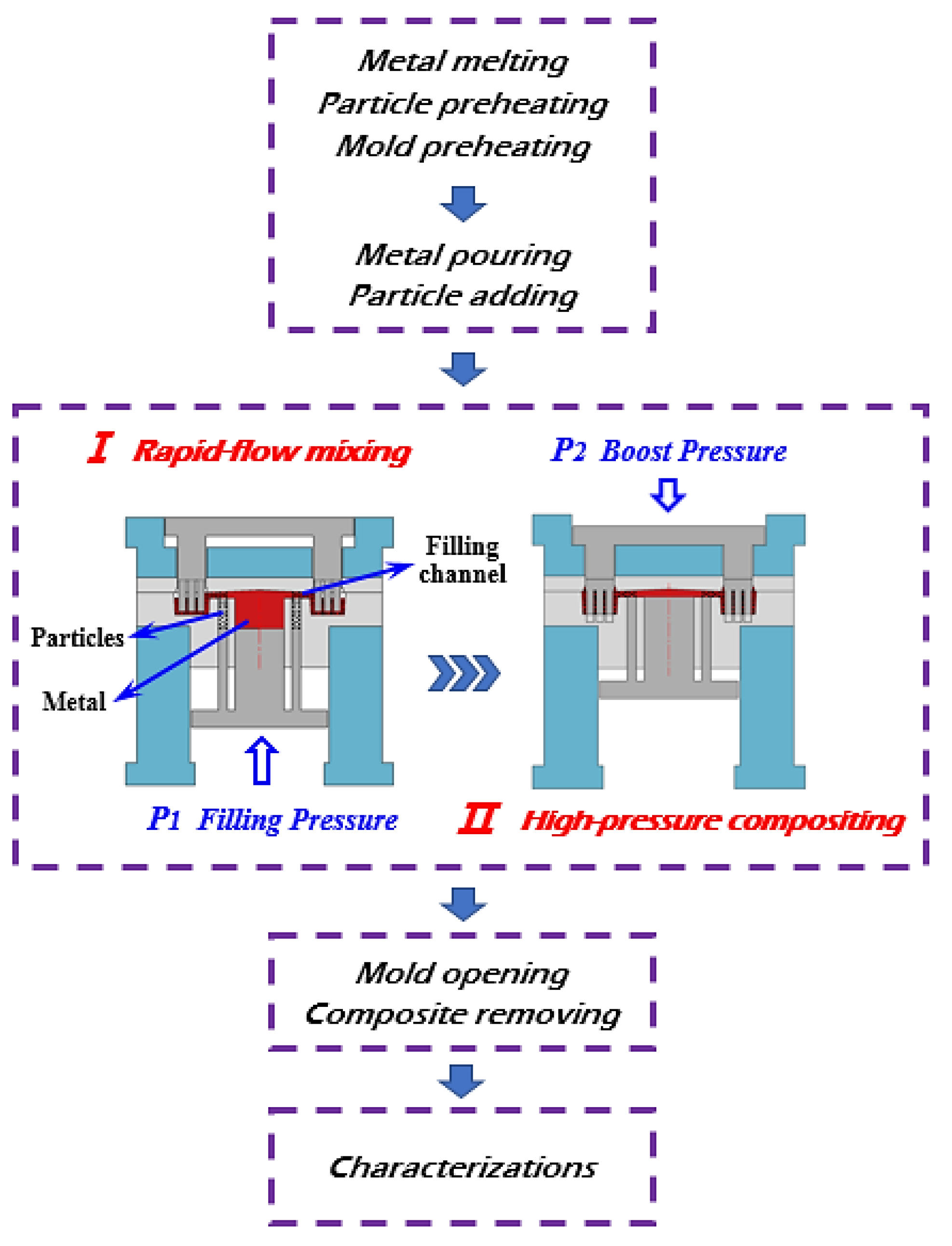
2.2. Preparation of Composite by Two-Step Process

Figure 1 shows a schematic diagram for fabricating ZTA/HCCI composite by a two-step process, which includes rapid-flow mixing followed by high-pressure compositing. The details of the preparation method were explained in an earlier study [19]. Prior to preparation, HCCI alloy was heated to over 1580 °C to melt, meanwhile, ceramic particle and the mold cavity was preheated to 1000 °C and 260 °C, respectively. Subsequently, molten HCCI was poured into the metal cavity and preheated ZTA particles were added into the ceramic cavities.
(1)
In the first step, the mold was closed and locked at the pressure of 115 MPa, then a filling pressure (P1) of 125 MPa was exerted to push molten iron and particles into the filling channel continuously at a high speed (150 mm/s). Then the particles were in contact with the molten iron and were wrapped by the rapidly flowing molten metal, thus achieving a uniform dispersion during the filling process. Subsequently, the metal-particle mixture was pushed into the workpiece cavities.
(2)
In the second step, the metal-particle mixture in the cavities was subjected to a boost pressure (P2) of 130 MPa to realize feeding and solidification and the pressure was maintain a certain time to achieve a tight bonding between the meal and particles.
(3)
After the solidification was completed, the boost pressure was removed and the mold was opened to obtain the ZTA/HCCI composite.

2.3. Instruments and Characterizations

As prepared composite was cut using a diamond cutting saw blade from the middle portion along the height direction to obtain the characterized samples. The distribution of reinforced particles was observed with an EVO 18 scanning electron microscopy (SEM, Carl Zeiss, Heidenheim, Germany) and analyzed using an Image-Pro Plus software (6.0, Media Cybernetics company, Rockville, MD, USA). The interfacial state of the composite was observed using SEM and a matched energy dispersive spectrometer (EDS, Bruker Nano GmbH, Berlin, Germany). The metallographic sample was prepared according to the conventional polishing technology and etched with 4% nital solution. Microstructural observations were carried out by employing a DM2000X optical microscopy (Leica, Weztlar, Germany) and SEM. Moreover, the phase composition of the composite was determined using an Ultima IV X-ray diffraction (XRD, Rigaku, Tokyo, Japan), and the test conditions included Cu target, Kα wavelength of 0.15406 nm, operating voltage of 40 kV, operating current of 100 mA, scanning speed of 8°/min, step size of 0.02°, and 2θ range of 20°–90°. Additionally, the hardness and impact toughness tests were performed to evaluate mechanical properties of the composite. In view of the macro-hardness of the composite is difficult to measure directly due to the relatively large size of the ZTA particles and the great hardness difference of the ZTA particles and HCCI matrix, the microhardness of the particle and the matrix was tested, respectively. The measurement was carried out using a MH-5L Vickers microhardness instrument (Hengyi, Beijing, China) under an applied load of 300 gf and held for 10 s. The impact toughness tests were performed with a JB-50 impact tester (Shidai, Beijing, China) using Charpy unnotched impact samples with a size of 10 × 10 × 55 mm3. Three samples were tested and the average value was taken as the result. After impact tests, the fracture surface was investigated with SEM to analyze the fracture mechanism of the composite.
Wear tests of the composite were carried out on a M-200 block-on-ring wear machine (Xuanhua Testing Equipment Co. Ltd., Xuanhua, China) under dry sliding condition at room temperature, ASTM G99-95A [20], as schematically shown in Figure 2. The block composite samples in dimension of 10 × 10 × 20 mm3 were pressed against a rotating GCr12 bearing steel ring (HRC 65 and Ra 0.2 μm) with a 40 mm outer diameter, 20 inner diameter and 10 mm in width. The test lasted for 30 min under an applied load of 300 and 900 N and a sliding speed of 200 r/min. Each test condition was repeated three times with new samples and the average was taken as the result. Before and after each test, the wear samples were cleaned in ethanol and weighed on a FA2104 electronic balance (Tianjin Tianma Hengji Instrument Co., Ltd., Tianjin, China) with an accuracy of 0.1 mg to measure the mass variation. Additionally, unreinforced HCCI prepared by the same method and the same process parameters as the composite was selected as the reference material for wear tests, and the relative wear resistance δ of the composite to unreinforced HCCI was used to evaluate the wear performance of the composite. The δ can be obtained by the following formula:
δ = Δ V m Δ V c = Δ M m ρ m / Δ M c α ρ p + ( 1 α ) ρ m
where Δ V m , Δ V c is the volume loss of the HCCI and composite samples, respectively; Δ M m , Δ M c is the weight loss of the HCCI and composite samples, respectively; ρ m , ρ p is the density of the HCCI matrix and ZTA particle, respectively; and α is the volume fraction of the particles inside the composite. The worn surface, worn sub-surface and counterpart ring surface morphologies were observed using SEM to analyze the wear characteristics and mechanisms of the composite.

3. Results and Discussion

3.1. Distribution and Interface

The particle distribution within the matrix and the interfacial bonding state of the particles and the matrix are presented in Figure 3. The ZTA particles are homogeneously distributed throughout the matrix and retain their original irregular appearance of angular shape, as shown in Figure 3a. Software analysis results show that the volume fraction of the particles inside the composite is approximately 54 vol.%. Moreover, a well bonded interface between the matrix and particles is exhibited with no obvious defects such as interfacial debonding or delamination. From the higher magnification image around the interface (Figure 3b), a tight and continuous interface is obtained, where no separation or cracks are presented. To further determine the type of interface bonding, EDS line scan analysis across the interface is carried out and the results are shown in Figure 3c. The distribution curves of the different elements change abruptly at the edge of interface, and there is no elemental diffusion are observed. The Fe and Cr are higher in the metal area, while the Al and Zr are remarkably low. In contrast, the contents of Al, Zr, and O are considerably high in the ceramic region, and Fe and Cr are almost absent. Additionally, there is no significant interfacial reaction is observed and no products are formed, which illustrates that the interface is bonded by mechanical locking.

3.2. Microstructure

Figure 4 shows the microstructure and XRD analysis result of the composite. As can be seen from Figure 4a, the bright phase is the HCCI matrix area and the dark one is the ZTA particle region. The matrix microstructure shows a typical dendritic structure, where the thin strips eutectic M7C3 carbides (M = Fe, Cr) are dispersed in the austenitic matrix (γ–Fe). Meanwhile, a small amount of martensite (α’–Fe) depicted in black are also observed in the edge of the austenitic or inside the carbides, as shown in the back scattered electron (BSE) image of the matrix (Figure 4b). Moreover, the carbides and austenitic have a smaller grain size of less than 10 and 50 μm, respectively. The formation of fine grains can be attributed to the application of high pressure, which promotes the heat transfer between the composite melts and the mold, thus resulting in a raise of the cooling rate during solidification. Subsequently, the undercooling of the melts increases, resulting in a higher nucleation rate, and then the finer grain is formed [21]. In addition, the microstructure of ZTA particle is shown in Figure 4c, where the ZrO2 with dendritic structures are distributed in the Al2O3 matrix. The EDS surface scanning of Figure 4b,c are performed and the results are shown in Figure 4b,c, respectively, which can further distinguish the different phases in matrix and reinforcement.
To identify the phase composition of the HCCI and composite, XRD analyses are performed and the results are shown in Figure 4d. The HCCI is mainly composed of M7C3, austenite and martensite, which is consistent with the previous report [22]. The formation of martensite was studied in the literature [23]; in this study, owing to the presence of strong carbide-forming elements such as Cr, Mo and W, some of the carbon in austenite are absorbed to form carbides during the solidification process, resulting in the regions around the austenite being carbon depleted. Moreover, some carbon and Cr diffuse into the eutectic carbides during the cooling and solidification process, which also reduces the solubility of carbon and Cr, and causes their depletion in the periphery of the austenite. Ultimately, the lack of carbon raises the martensite start temperature (Ms), allows austenite partially transforming to martensite during the cooling and solidification process.
Additionally, the composite mainly consists of Al2O3, Zr2O (t–ZrO2 and m–ZrO2), M7C3, austenite, and martensite. For the reinforced phase ZTA, owing to the difference in thermal expansion coefficient between Al2O3 and Zr2O, Al2O3 restrains the volume expansion of Zr2O during the cooling process, and Zr2O exists in its metastable tetragonal phase (t–ZrO2). Meanwhile, during the solidification process of the composite, thermal residual stress is generated at the interface due to the thermal expansion coefficient between the particle reinforcement and metal matrix are different [24]. Owing to the existence of thermal stress, the inhibition of the Al2O3 to the tetragonal ZrO2 is weakened, and then the phase transformation of ZrO2 occurs, the metastable tetragonal phase transits to the stable monoclinic phase (t–ZrO2 → m–ZrO2). Therefore, m–ZrO2 phase is detected in the composite.

3.3. Mechanical Properties

Figure 5 shows the microhardness and impact toughness values of the HCCI and composite. For the composite, five data were measured in matrix and particle areas, respectively. The hardness distribution curve from matrix to particle area is described in green line, which shows that the average value is 823.1 ± 1.58 HV for matrix and 1834.6 ± 4.59 HV for particle. For the HCCI, 11 hardness values were measured (red line) and the average is 825.3 ± 3.43 HV. During the wear process, the reinforced particles with high hardness can restrain the partial plastic deformation and effectively resist the wear of the abrasive, thus protecting the matrix from wearing and improving the wear properties of the composite. Conversely, the metal matrix with certain hardness and good toughness can play a supporting role to ceramic particles to avoid the shedding of the particles [25].
In addition, the results of impact toughness tests of the HCCI and composite can also be found in Figure 5. The toughness of the composite (6.67 J·cm−2) is significantly lower than that of the HCCI (9.27 J·cm−2), which can be attributed to the following aspects. First, the reinforcement of the composite is the ceramic particle with a high brittleness, who has a poor tendency to resist rapid propagation of cracks [26]. When the stress transmitted from the matrix to the particles increases, microcracks are easily generated from the interior of the particles, thus resulting in a lower toughness of the composite. Besides the undeniable effect of the presence of the particles, the size and volume fraction of the particles are also the crucial factors affecting the toughness of the composite [27,28]. In this study, the ZTA particles are macroscopical, which are prone to breaking and thus leading to a significant decrease in composite toughness. Moreover, the reinforced ZTA has a higher volume fraction in composite (54 vol.%), which is also related to the lower toughness of the composite.
The fractured surface morphologies of the composite are exhibited in Figure 6. As can be seen from the low magnification image (Figure 6a), the fracture appears inside the particles and the sections are clearly visible, indicating that there is a relatively strong bonding between the matrix and ceramic particles. This is consistent with the report of Carvalho et al. [29], who found the application of pressure can effectively improve the interfacial bonding strength, and the fracture of the composite passes through the interior of the particles rather than breaking along the surface of the particles. Additionally, the higher magnification graph of fracture surface (Figure 6b) shows that the fracture mode of the matrix is dominated by a ductile fracture, which is characterized by the existence of shallow dimples. Moreover, the EDS analysis results of the regions 1 and 2 in Figure 6b are displayed in Figure 6c,c′. As shown, area 1 is constituted by the HCCI matrix, which mainly includes elements Fe and Cr, whereas region 2 is the ceramic particle, containing the main elements Al, O and Zr.

3.4. Wear Property

3.4.1. Wear Resistance of the Composite

The volume loss of the HCCI and composite as a function of wear time under applied load of 300 and 900 N are shown in Figure 7a. As shown, the volume loss of the two materials increases with sliding time and exhibits an approximately liner tendency. The composite shows a lower volume loss than that of the HCCI during the wear process under different loads. Moreover, the average wear rate (volume loss/sliding time) of the HCCI is calculated to be between 0.0191 and 0.11 mm3/min when the load increases from 300 to 900 N, whereas the corresponding values of the composite are 0.0149 and 0.0365 mm3/min, which is much smaller than that of the HCCI. Figure 7b shows the relation of cumulative volume loss (total volume loss after wear test) and applied load of the HCCI and composite and the relative wear resistance of the composite to HCCI under 300 and 900 N. The cumulative volume loss of the two materials all increases with applied load, and the HCCI has a higher loss than the composite under different loads, indicating that the composite has a better wear resistance in comparison with HCCI. According to the calculation result of the relative wear resistance of the composite to HCCI (inserted graph in Figure 7b), if the wearability of the HCCI is regarded as 1, the wear resistance of the composite is 1.8 to 2.9 times higher that of the HCCI when the applied load increases from 300 to 900 N, which illustrates the wear resistance of the composite is much better at higher load.

3.4.2. Worn Surface of the Composite

To determine the wear mechanisms of the tested materials, the worn surface morphologies of the HCCI alloy and the composite after wear tests at 300 and 900 N were observed by SEM, as shown in Figure 8 and Figure 9, respectively. It is visible that the worn surfaces of the HCCI alloy exhibited a higher surface roughness in comparison with the composite, which are evidenced by numbers of deep and continuous plowing grooves, intense plastic deformation, and obvious adhesive characteristics, indicating that the HCCI experienced a more serious sliding wear than the composite.
Figure 8a,b shows the worn surfaces of the HCCI under a lower load (300 N), the plowing grooves parallel to the sliding direction, detaching debris, plastic deformation, and softened area appear on the worn surface. Due to the mechanical machining of the friction ring, there are plenty of micro-asperities on the ring surface. During the wear process, the asperities can plow the surface of the HCCI, who have a relatively low hardness, thus leading to the obvious grooves and producing massive fine particles [30]. Then the fine particles from the friction pair to form the wear debris. EDS analysis also illustrated that the wear debris was mainly Fe and Cr, and a small number of other elements (67.7Fe–17.1Cr–7.7O–4.8C–0.6Si–0.96Mn–1.04Ni, wt%), indicating that they were primarily detached from HCCI. In addition, at initial stage of the wear process, the actual contact between friction pairs is a local contact, thus the actual heat conduction area is smaller than the theoretical value, and then a flash temperature was produced locally on the sample surface [31], causing the formation of the softened area on the surface. Moreover, plastic deformation is also prone to occurring owing to the local softening of the material surface [32]. Hence, at lower load, the wear mechanism of the HCCI is mainly abrasive wear.
When the applied load increases to 900 N, the worn surface of the HCCI is characterized by significant adhesive area, delamination, and plowing grooves, as shown in Figure 8c. As the applied load rises to a higher level, the friction heat produced during the wear process rises sharply, resulting in an obvious increase in temperature of the counterface. When the temperature reaches a critical value, the material softens and the shear strength of the material surface decreases. Therefore, material transfer occurs under the sliding of the counterface and leads to adhesive wear [33]. Moreover, obvious plastic flow can be observed from the high magnification image (Figure 8d). Under a higher load, the increased compressive stress promotes the increase of adhesive area and adhesive strength of the counterface, causing the adhesions are prone to developing into plastic flow [34]. Additionally, the softened area on the surface is subjected to the periodic loads in the wear process, and the plastic shear deformation of the subsurface accumulates constantly, then the fatigue phenomena appears and the cracks are formed [35]. Under the combined action of ring rotation and external force, the cracks spread and converge with each other, then the delamination is formed, and resulting in a sharp increase in wear [36]. Therefore, the wear mechanisms of the HCCI at higher load are mainly adhesive wear, plastic flow, and delamination.
When the ZTA particles are introduced into the HCCI, the ZTA/HCCI composite exhibits a highly improved wear resistance. Figure 9 shows the SEM images of the worn surface of the composite under different wear conditions. Under the applied load of 300 N, the worn surface is relatively smooth with slight worn trace, which is manifested as no clear marks of scratching on the reinforced particles, and numbers of shallow and narrow grooves are found on the matrix surface. Moreover, an area against wear of counterpart ring owing to the protection of ZTA particles can also be observed, where no obviously grooves are visible. This is consistent with the clearly increase of the wear resistance of the composite shown in Figure 7b. In fact, the reasons for the improvement in the wear resistance of the composite can be explained as follows. The additional ZTA particles and the eutectic M7C3 carbide play a strengthening role to the matrix, who increase the macro-hardness of the composite and can effectively resist plowing and cutting of the counterpart ring. Meanwhile, the reinforced particles have a good load-bearing capacity, which can endure the most of load applied to the wear region, thus reducing the plastic deformation of the surface. Conversely, the HCCI matrix with good toughness and strength can play a holding role to the reinforced phase, so that the particles can avoid detaching from the matrix during the wear process. Therefore, the wear resistance of the composite is significantly improved. The magnified graph at the interface is shown in Figure 9b, there is a spot of debris around the interface, but no obvious cracking or debonding are observed, which indicates that the matrix and particles are in a state of tight bonding. In this condition, the wear mechanism of the composite is mainly slight abrasive wear.
As the applied load increases to 900 N, the worn surface of the composite mainly consists of fragmentation of ZTA particles, transfer layer, and interface cracking, as shown in Figure 9c. It is known that the applied load is one of the crucial factors affecting the wear characteristics of the composite during the sliding wear process [37]. The raise of the load results in an increase of the actual contact area of the counterface. Then the temperature of the worn surface increases, causing its bearing capacity decreases. As a result, the metal area on the composite surface is gradually worn, then the holding effect of the matrix to particles is weaken and the particles are more prominent than the matrix. Subsequently, under the sustained action of high contact stress, the ZTA particle is subjected to most of the load, and then a microcrack emerges when the force reaches the limit of fracture strength of the particles. In consequence, the fragmentation and partial detachment of the ZTA particles appear, causing an increase in the wear of the composite material. In addition, the worn surface deforms locally and presents a transfer layer along the sliding direction. Under the action of higher load, the worn surface undergoes a serious plastic deformation due to the pushing and grinding action of the friction ring. Meanwhile, microcracks are easily generated in some fragile areas on the worn surface, then the cracks propagate and converge with the reciprocating motion of the counterpart ring [38]. As a result, the combined effect of plastic deformation and cracks leads to the formation of a sheet-like transfer layer, and further, the layer breaks and detaches as the wear process progresses, eventually resulting in material loss.
Additionally, the slight debonding of the interface can be further observed from the magnified view around the interface (Figure 9d). The particles near the interface are cracked and the ceramic fragments are visible. Although the interfacial bonding in the present composite is tight, at higher load, an increase in frictional heat softens the worn surface, and decreases the interfacial bonding strength of the composite. With sliding and pressure, the debonding of the interface occurs when the friction tangential stress is greater than the interfacial bonding strength. Moreover, the ceramic on the surface is subjected to the normal and shear stresses of the rotating ring, resulting in the rough surface becoming relatively smooth, as shown in Figure 9d.

3.4.3. Worn Sub-Surface of the Composite

Worn sub-surfaces of the HCCI under different loads are shown in Figure 10. The wear trace at 900 N is wider than that of at 300 N, meanwhile, the max depth of the wear trace at 900 N is a little higher (~60 μm) in comparison with 300 N (~30 μm), as shown in the low magnification graphs (Figure 10a,c). This is accord with the fact that the volume loss of the HCCI is higher under 900 N (Figure 7). From the high magnification diagrams, the deformation direction of the subsurface is consistent with the sliding direction under different conditions. As mentioned earlier, the shear strength of the surface decreases due to the raise of the temperature under applied load. With the rotation of the friction ring, when the strength of the adhesive point is higher than that of the contact point of the counterface, the plastic deformation of these positions occurs along the sliding direction. Moreover, the softened zones are visible on the subsurface under the load of 300 N (Figure 10b), which is related to the increase of local temperature caused by frictional heat. The adhesive characterizations can be clearly observed from the subsurface at 900 N (Figure 10d). Meanwhile, the cracks on the subsurface are visible, which is the origin of the delamination phenomenon.
Worn sub-surfaces of the composite corresponding to different loads are shown in Figure 11. Under the applied load of 300 N, the worn area and the protected area can be clearly seen in Figure 11a, which is consistent with Figure 9a. As mentioned above, the reinforced particles can play a role in protecting the metal matrix in the composite due to their relatively high hardness. Meanwhile, it should be noted that the protection effect is related to the relative position of the matrix metal and reinforced particles and the friction direction [39]. The area behind the particles has a smaller wear loss in contrast to the area in front of the particles along the sliding direction, as shown in Figure 11a. This can be further seen from Figure 11b, where the metal and particles are almost in the same planer, no obvious loss is exhibited in metal area. Additionally, the microcrack generated inside the particle can be observed.
Under the applied load of 900 N, the worn surface experienced a more severe wear process, manifesting as obvious wear of matrix and breakage of particles, as shown in Figure 11c. The details of wear trace and fragmentation can be seen from the high magnified view (Figure 11d). The worn surface of the composite is subjected to repeated effects of applied pressure and tangential friction force. Thus, the cumulative plastic deformation on the matrix surface causes the obvious wear trace. In addition, although the interface has a strong bonding strength, the microcracks are prone to be initiated and propagate along the mechanically bonded interface under the reciprocating action of high load, thus resulting in the breakage of particles at the interface.

3.4.4. Worn Surface of the Counterpart Ring

Figure 12 shows the worn surface morphologies of the counterpart ring corresponding to the composite at loads of 300 N (a,b) and 900 N (c–e). There are continuous and fine furrows on the ring surface under the load of 300 N, which are caused by the plowing effect of the ceramic particles exposed to the composite surface under the action of normal force. For the ring surface corresponding to 900 N, the debris and obvious adhesion are visible (Figure 12c). The production of debris is derived from plowing effect, and the adhesion comes from the material transfer. Moreover, as can be seen from the magnified graph of the ring surface (Figure 12d), it is locally covered by a layer of black dense material and the layer adheres tightly with the surface. The EDS analysis (Figure 12e) indicates that the layer is highly enriched in Fe and O elements, which is identified as an oxidation mixed film, indicating that oxidation phenomenon occurs on the counterface during the wear process. As mentioned above, the fine particles and debris are produced due to the ring surface is plowed, the particles and debris are mixed between the counterface, then an iron-rich oxidation adhesive layer is formed under the action of external force and frictional heat. This result is consistent with the findings of Maire et al. [40] and Chawla and Shen [41].

4. Conclusions

The HCCI matrix composite reinforced with ZTA particles 2–3 mm in size was fabricated by a two-step method termed rapid-flow mixing followed by high-pressure compositing. This method required neither coating particles nor using preforms in advance. The microstructure, mechanical properties and dry sliding wear property of the fabricated composite were investigated, and the main conclusions can be summarized as follows:
(1)
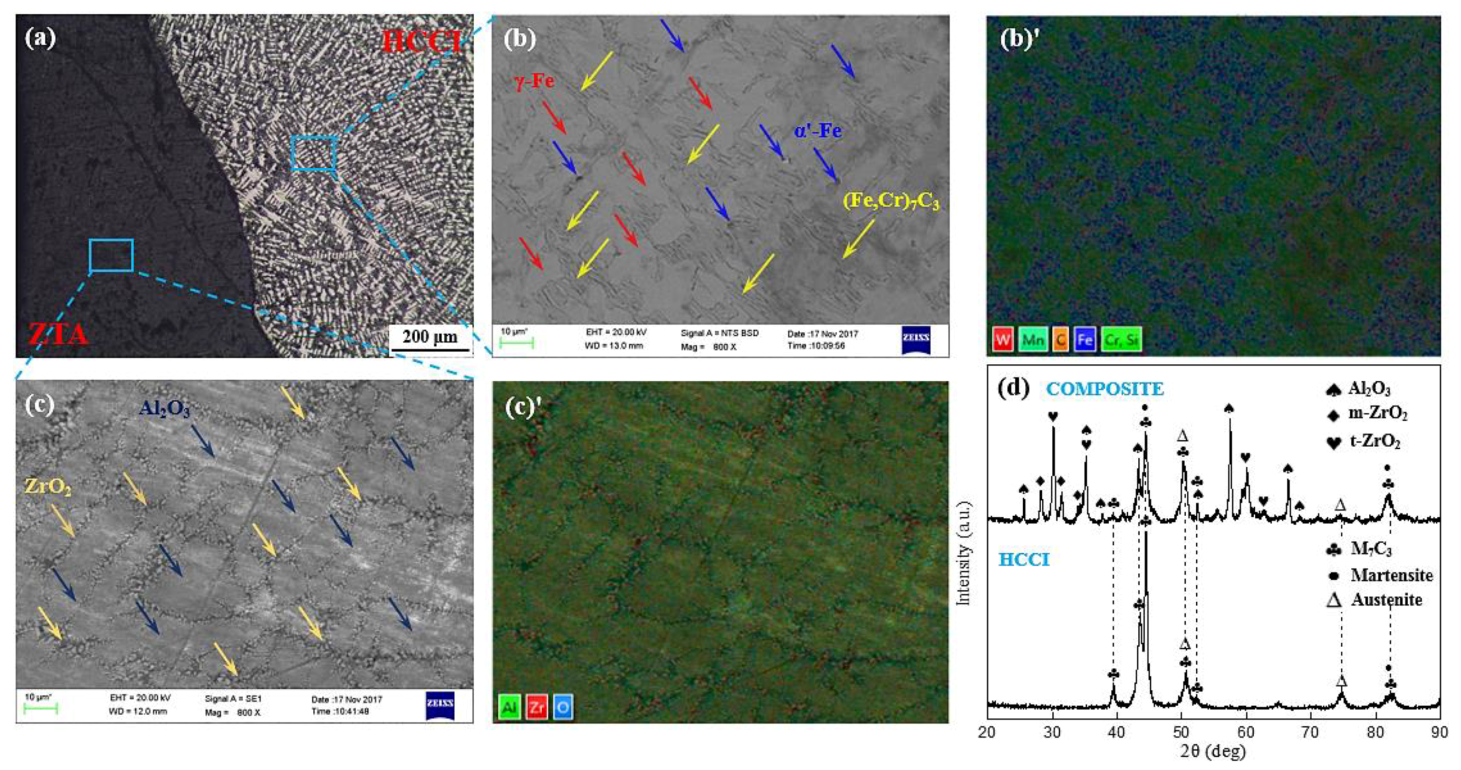
In the prepared composite, the ZTA particles were distributed homogeneously inside the HCCI matrix, and the interface combined by mechanical bonding was tight, clear and smooth, where no debonding or other defects were observed. The XRD results showed that the composite mainly consists of Al2O3, t–ZrO2, m–ZrO2, M7C3, austenite, and martensite.
(2)
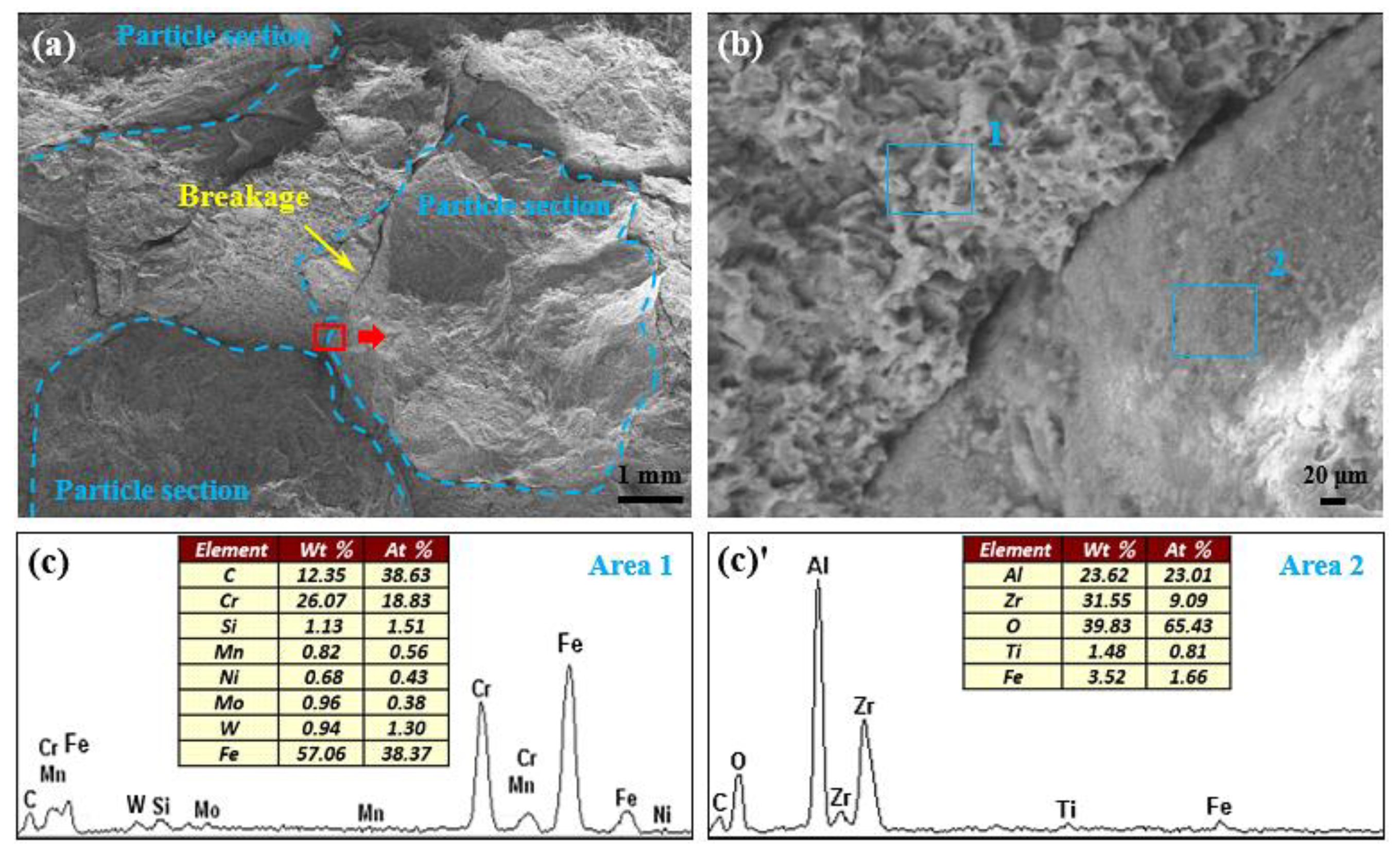
The impact toughness of the composite (6.67 J·cm−2) is significantly lower than that of the HCCI alloy (9.27 J·cm−2). The fracture surface morphology of the composite showed that the fracture appears inside the particles, indicating a relatively strong bonding between the matrix and particles. Moreover, the fracture mode of the matrix is dominated by a ductile fracture.
(3)
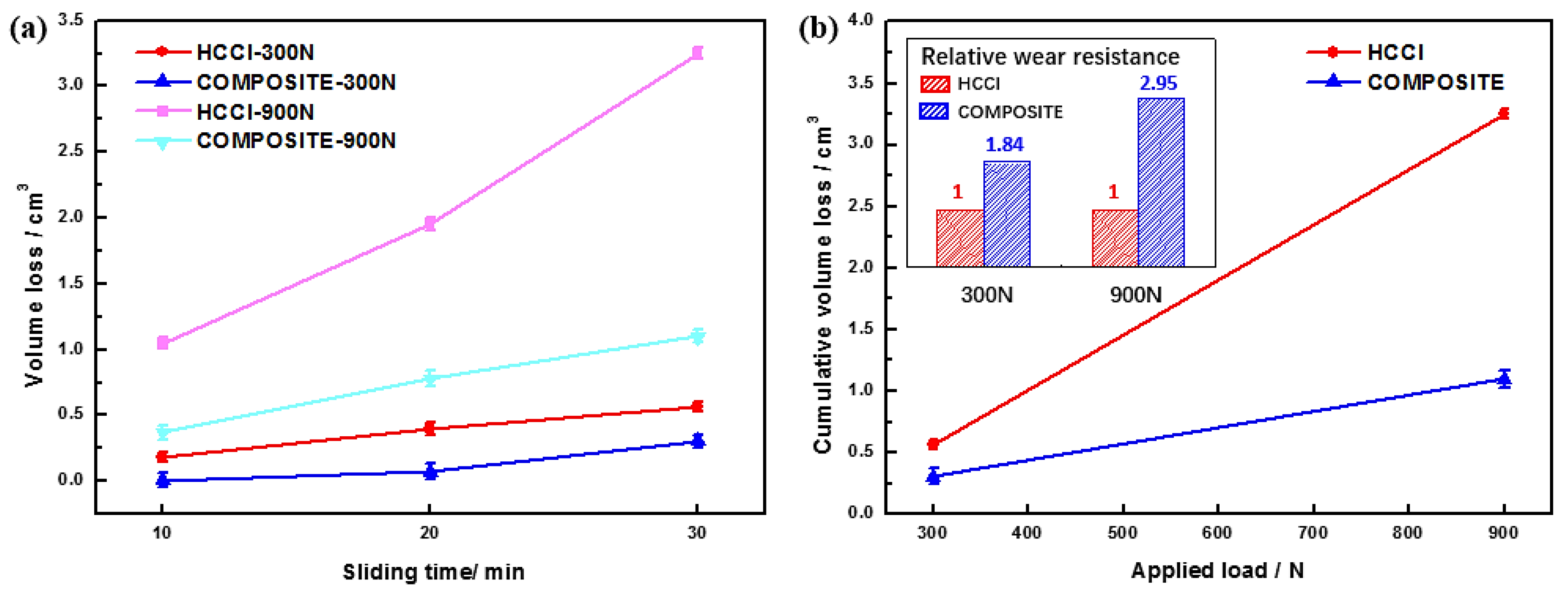
Under dry sliding wear conditions, the wear resistance of the composite is obviously higher than that of the unreinforced HCCI material, and the relative wear resistance of the composite to HCCI increased from 1.8 to 2.9 times when the applied load varied from 300 to 900 N, which indicated the wear resistance of the composite is much better at higher load.
(4)
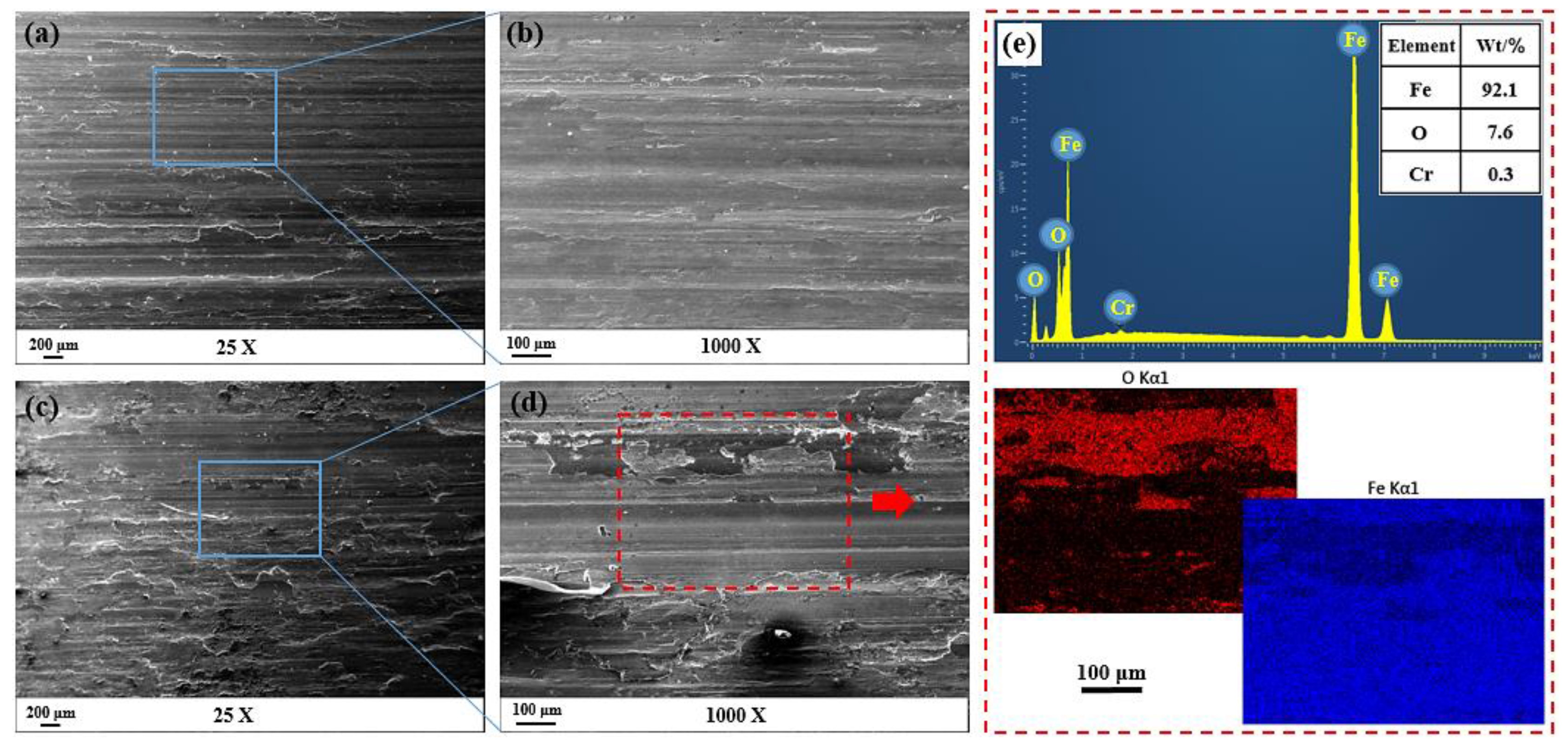
The wear mechanism of the composite is mainly slight abrasive wear under lower applied load (300 N), which is manifested as relatively shallow and narrow grooves and scratches, while the wear characteristics of fragmentation of particles, transfer layer and interface cracking dominate the wear process when the applied load is higher (900 N).

Author Contributions

Methodology, S.X. and B.Q.; experiment, B.Q. and Q.D.; data analysis, B.Q.; validation, S.X., B.Q. and Q.D.; writing—original draft preparation, B.Q.; writing—review and editing, S.X., B.Q. and Q.D.; supervision, S.X.; funding acquisition, S.X.

Funding

This research was funded by the Fundamental Research Funds for the Central Universities under Grant No. 2018YJS139.

Conflicts of Interest

The authors declare no conflict of interest.

References

  1. Alejandro, G.P.; Florentino, A.A.; Juan, A.L. Erosive Wear Resistance Regarding Different Destabilization Heat Treatments of Austenite in High Chromium White Cast Iron, Alloyed with Mo. Metals 2019, 9, 522. [Google Scholar] [Green Version]
  2. Christian, H.; Luis, A.B.M. From High-Manganese Steels to Advanced High-Entropy Alloys. Metals 2019, 9, 726. [Google Scholar] [Green Version]
  3. Song, B.; Dong, S.J.; Coddet, P.; Zhou, G.S.; Ouyang, S.; Liao, H.L.; Coddet, C. Microstructure and tensile behavior of hybrid nano–micro SiC reinforced iron matrix composites produced by selective laser melting. J. Alloy. Compd. 2013, 579, 415–421. [Google Scholar] [CrossRef]
  4. Li, J.; Zong, B.Y.; Wang, Y.M.; Zhuang, W.B. Experiment and modeling of mechanical properties on iron matrix composites reinforced by different types of ceramic particles. Mat. Sci. Eng. A 2010, 527, 7545–7551. [Google Scholar] [CrossRef]
  5. Zhao, Z.Y.; Li, J.; Bai, P.K.; Qu, H.Q.; Liang, M.J.; Liao, H.H.; Wu, L.Y.; Huo, P.C.; Liu, H.; Zhang, J.X. Microstructure and Mechanical Properties of TiC–Reinforced 316L Stainless Steel Composites Fabricated Using Selective Laser Melting. Metals 2019, 9, 267. [Google Scholar] [CrossRef]
  6. Chukwuma, O.; Zhila, R.; Georges, K.; Zoheir, F.; Kevin, P. The Aqueous Electrochemical Response of TiC–Stainless Steel Cermets. Metals 2018, 8, 398. [Google Scholar]
  7. Zhang, Z.Z.; Chen, Y.B.; Zhang, Y.; Gao, K.W.; Zuo, L.L.; Qi, Y.S.; Wei, Y. Tribology characteristics of ex-situ and in situ tungsten carbide particles reinforced iron matrix composites produced by spark plasma sintering. J. Alloy. Compd. 2017, 704, 260–268. [Google Scholar] [CrossRef]
  8. Li, Z.L.; Jiang, Y.H.; Zhou, R.; Lu, D.H.; Zhou, R.F. Dry three–body abrasive wear behavior of WC reinforced iron matrix surface composites produced by V–EPC infiltration casting process. Wear 2007, 262, 649–654. [Google Scholar] [CrossRef]
  9. Zhou, M.J.; Sui, Y.D.; Chong, X.Y.; Jiang, Y.H. Wear Resistance Mechanism of ZTAp/HCCI Composites with a Honeycomb Structure. Metals 2018, 8, 588. [Google Scholar] [CrossRef]
  10. Armelle, P.; Bernard, H.L.; Jérôme, C.; Laurent, G.; Bruno, R.; Frédéric, F.; Jiunn–Der, L.; Jean, G. Ageing, Shocks and Wear Mechanisms in ZTA and the Long-Term Performance of Hip Joint Materials. Materials 2017, 10, 569. [Google Scholar] [Green Version]
  11. Chen, X.D.; Betke, U.; Rannabauer, S.; Peters, P.C.; Söffker, G.M.; Scheffler, M. Improving the Strength of ZTA Foams with Different Strategies: Immersion Infiltration and Recoating. Materials 2017, 10, 735. [Google Scholar] [CrossRef]
  12. Zheng, K.H.; Gao, Y.M.; Li, Y.F.; Zhao, S.M.; Wang, J. Three-body abrasive wear resistance of iron matrix composites reinforced with ceramic particles. Proc. Inst. Mech. Eng. 2014, 228, 3–10. [Google Scholar] [CrossRef]
  13. Ru, J.J.; He, H.; Jiang, Y.H.; Zhou, R.; Hua, Y.X. Wettability and interaction mechanism for Ni-modified ZTA particles reinforced iron matrix composites. J. Alloy. Compd. 2019, 786, 321–329. [Google Scholar] [CrossRef]
  14. Fan, L.; Wang, Q.; Yang, P.; Chen, H.H.; Hong, H.P.; Zhang, W.T.; Ren, J. Preparation of nickel coating on ZTA particles by electroless plating. Ceram. Int. 2018, 44, 11013–11021. [Google Scholar] [CrossRef]
  15. Zhou, M.J.; Jiang, Y.H.; Chong, X.Y. Interface transition layer interaction mechanism for ZTAp/HCCI composites. Sci. Eng. Compos. Mater. 2018, 25, 881–890. [Google Scholar] [CrossRef]
  16. Chen, Z.H.; Xiong, H.; Sun, G.X.; Lu, Y.Q. A preliminary study on casting infiltration technology of wear-resistant castings. Cem. Guide New Epoch 2015, 2, 10–15. (In Chinese) [Google Scholar]
  17. Francois, H. Composite wear component. US Patent US00RE39998E, 8 January 2008. [Google Scholar]
  18. Tang, S.L.; Gao, Y.M.; Li, Y.F. Recent developments in fabrication of ceramic particle reinforced iron matrix wear resistant surface composite using infiltration casting technology. Ironmak. Steelmak. 2014, 41, 633–640. [Google Scholar] [CrossRef]
  19. Qiu, B.; Xing, S.M.; Dong, Q. Fabrication and wear behavior of ZTA particles reinforced iron matrix composite produced by flow mixing and pressure compositing. Wear 2019, 428, 167–177. [Google Scholar] [CrossRef]
  20. ASTM-G99–05, Standard Test Method for Wear Testing with A Pin–on–Disc Apparatus; ASTM International: West Conshohocken, PA, USA, 1997.
  21. Khodaverdizadeh, H.; Niroumand, B. Effects of applied pressure on microstructure and mechanical properties of squeeze cast ductile iron. Mater. Des. 2011, 32, 4747–4755. [Google Scholar] [CrossRef]
  22. Tabrett, C.P.; Sare, I.R.; Ghomashchi, M.R. Microstructure-property relationships in high chromium white iron alloys. Int. Mater. Rev. 1996, 41, 59–82. [Google Scholar] [CrossRef]
  23. Bedolla-Jacuinde, A. Microstructure of vanadium-, niobium- and titanium-alloyed high-chromium white cast irons. Int. J. Cast. Metal. Res. 2001, 13, 343–361. [Google Scholar] [CrossRef]
  24. Rosso, M. Ceramic and metal matrix composites: Routes and properties. J. Mater. Process. Technol. 2006, 175, 364–375. [Google Scholar] [CrossRef]
  25. Ye, F.X.; Hojamberdiev, M.; Xu, Y.H.; Zhong, L.S.; Zhao, N.N.; Li, Y.P.; Huang, X. Microstructure, microhardness and wear resistance of VCp/Fe surface composites fabricated in situ. Appl. Surf. Sci. 2013, 280, 297–303. [Google Scholar] [CrossRef]
  26. Singh, J.; Chauhan, A. Characterization of hybrid aluminum matrix composites for advanced applications—A review. J. Mater. Res. Technol. 2016, 5, 159–169. [Google Scholar] [CrossRef]
  27. Barmouz, M.; Asadi, P.; Besharati Givi, M.K.; Taherishargh, M. Investigation of mechanical properties of Cu/SiC composite fabricated by FSP: Effect of SiC particles’ size and volume fraction. Mat. Sci. Eng. A 2011, 528, 1740–1749. [Google Scholar] [CrossRef]
  28. Tao, Y.Y.; Ge, X.L.; Xu, X.J.; Jiang, Z. Influences of SiC Particle Size and Content on the Mechanical Properties and Wear Resistance of the Composites with Al Matrix. Key Eng. Mater. 2008, 375, 430–434. [Google Scholar] [CrossRef]
  29. Carvalho, O.; Madeira, S.; Buciumeanu, M.; Soares, D.; Silva, F.S.; Miranda, G. Pressure and sintering temperature influence on the interface reaction of SiCp/410L stainless steel composites. J. Compos. Mater. 2015, 50, 4491–4503. [Google Scholar] [CrossRef]
  30. Tan, H.; Luo, Z.; Li, Y.; Yan, F.; Duan, R.; Huang, Y. Effect of strengthening particles on the dry sliding wear behavior of Al2O3–M7C3/Fe metal matrix composite coatings produced by laser cladding. Wear 2015, 324–325, 36–44. [Google Scholar] [CrossRef]
  31. Ashby, M.F.; Abulawi, J.; Kong, H.S. Temperature Maps for Frictional Heating in Dry Sliding. Tribol. Trans. 1991, 34, 577–587. [Google Scholar] [CrossRef]
  32. Gou, J.F.; Wang, Y.; Sun, Z.; Li, X.W. Study of work function and dry sliding wear behavior of Fe-based hardfacing alloys with and without nano rare earth oxides. J. Alloy. Compd. 2017, 713, 255–265. [Google Scholar] [CrossRef]
  33. Subramaniam, C. Some considerations towards the design of a wear resistant aluminium alloy. Wear 1992, 155, 193–205. [Google Scholar] [CrossRef]
  34. Jacuinde, A.B.; Rainforth, W.M. The wear behaviour of high-chromium white cast irons as a function of silicon and Mischmetal content. Wear 2001, 250, 449–461. [Google Scholar] [CrossRef]
  35. Pan, R.; Ren, R.M.; Zhao, X.J.; Chen, C.H. Influence of microstructure evolution during the sliding wear of CL65 steel. Wear 2018, 400, 169–176. [Google Scholar] [CrossRef]
  36. Zhang, Q.; Jiang, Z.Y.; Wei, D.B.; Zhu, H.T.; Chen, Z.X.; Han, J.T.; Xie, G.L. Interface adhesion during sliding wear in cast iron after hot deformation. Wear 2013, 301, 598–607. [Google Scholar] [CrossRef]
  37. Alidokht, S.A.; Abdollah-Zadeh, A.; Assadi, H. Effect of applied load on the dry sliding wear behaviour and the subsurface deformation on hybrid metal matrix composite. Wear 2013, 305, 291–298. [Google Scholar] [CrossRef]
  38. Suresha, S.; Sridhara, B.K. Effect of addition of graphite particulates on the wear behaviour in aluminium–silicon carbide–graphite composites. Mater. Des. 2010, 31, 1804–1812. [Google Scholar] [CrossRef]
  39. Liu, J.; Yang, S.; Xia, W.S.; Jiang, X.; Gui, C.B. Microstructure and wear resistance performance of Cu–Ni–Mn alloy-based hardfacing coatings reinforced by WC particles. J. Alloy. Compd. 2016, 654, 63–70. [Google Scholar] [CrossRef]
  40. Maire, E.; Wilkinson, D.S.; Embury, J.D.; Fougeres, R. Role of damage on the flow and fracture of particulate reinforced alloys and metal matrix composites. Acta Mater. 1997, 45, 5261–5274. [Google Scholar] [CrossRef]
  41. Chawla, N.; Shen, Y.L. Mechanical Behavior of Particle Reinforced Metal Matrix Composites. Adv Eng Mater. 2001, 3, 357–370. [Google Scholar] [CrossRef]
Figure 1. Schematic diagram for fabricating the composite by two–step process.
Metals 09 00986 g001
Figure 2. Schematic illustration of the block-on-ring type wear test machine.
Metals 09 00986 g002
Figure 3. (a) Particle distribution; (b) Interfacial bonding state; (c) EDS (energy dispersive spectrometer) line scan analysis and results across the interface.
Metals 09 00986 g003
Figure 4. (ac′) Microstructure of the composite; (d) XRD analysis result of the composite.
Metals 09 00986 g004
Figure 5. Microhardness and impact toughness results of the HCCI (high chromium cast iron) and composite.
Metals 09 00986 g005
Figure 6. (a) Fracture surface of the composite at low magnification; (b) Fracture surface of the composite at high magnification; (c,c′) EDS (energy dispersive spectrometer) analysis results of the regions 1 and 2 in (b).
Metals 09 00986 g006
Figure 7. (a) The volume loss of as a function of sliding time under different loads; (b) the relation of cumulative volume loss and applied load and the relative wear resistance of the composite to HCCI.
Metals 09 00986 g007
Figure 8. The worn surface morphologies of the HCCI under different loads: (a) 300 N-low magnification; (b) 300 N-high magnification; (c) 900 N-low magnification; (d) 900 N-high magnification.
Metals 09 00986 g008
Figure 9. The worn surface morphologies of the composite under different loads: (a) 300 N-low magnification; (b) 300 N-high magnification; (c) 900 N-low magnification; (d) 900 N-high magnification.
Metals 09 00986 g009
Figure 10. The worn sub-surface morphologies of the HCCI alloy under different loads: (a,b) 300 N; (c,d) 900 N.
Metals 09 00986 g010
Figure 11. The worn sub-surface morphologies of the composite under different loads: (a,b) 300 N; (c,d) 900 N.
Metals 09 00986 g011
Figure 12. The worn surface morphologies of the counterpart ring under different load: (a,b) 300 N; (ce) 900 N.
Metals 09 00986 g012
Table 1. The physical and mechanical properties of the ZTA (ZrO2–toughened Al2O3) particles.
Composition (vol.%)Particle Size (mm)Density (g·cm−3)Melting Point (°C)Hardness (HV)Fracture Toughness (MPa·m1/2)
Al2O3–60%
ZrO2–40%
2–34.019001700–19007.0

