Article

Effect of Alternating Magnetic Field on the Fatigue Behaviour of EN8 Steel and 2014-T6 Aluminium Alloy

1
School of Engineering and Computer Science, University of Hertfordshire, College Lane, Hatfield AL10 9AB, UK
2
Department of Design and Engineering, Faculty of Science and Technology, Bournemouth University, Poole House, Talbot Campus, Fern Barrow, Poole BH12 5BB, UK
3
Institute of Physics of Materials, Academy of Sciences of the Czech Republic, v.v.i., Žižkova 22, CZ61662 Brno, Czech Republic
*
Author to whom correspondence should be addressed.
Metals 2019, 9(9), 984; https://doi.org/10.3390/met9090984
Submission received: 2 August 2019 / Revised: 23 August 2019 / Accepted: 26 August 2019 / Published: 4 September 2019

Abstract

:
The application of an alternating magnetic field (0.54 T) was observed to lead to an improvement in the fatigue endurance and an increase in Vickers microhardness and tensile strength of both EN8 steel and AA2014-T6 alloy. Fractography using scanning electron microscopy showed evidence of more ductile fracture features after treatment in contrast to untreated samples. The results of X-ray diffraction indicated formation of more compressive residual stresses following treatment; while examination by transmission electron microscopy showed evidence of fewer dislocations. In the case of the AA2014-T6 alloy; Guinier-Preston (GP) zones were also generated by the alternating magnetic field. However; the temperature increase during the treatment was too low to explain these observations. The results were attributed to the non-thermal effect of the alternating magnetic field treatment that led to depinning and movement of dislocations and secondary precipitation of copper.

1. Introduction

Fatigue, alongside corrosion and wear, are the main causes of damage in metallic members and structures [1]. If ignored, fatigue can lead to catastrophic failure and financial loss in many sectors, including the aerospace, automotive and marine industries. About 90% of all metallic failures are estimated to be due to fatigue failure [2]. Fatigue is thought of as an inevitable and irreversible process in metallic components that are subjected to repetitive stresses over time [3,4,5]. These repeated stresses create micro-flaws within the microstructure leading to fatigue damage. Improving fatigue life can be accomplished by reducing the strain magnitude a material is exposed to or by taking action to increase the number of stress cycles that the material can withstand. For example, reducing the magnitude of the induced stress can be easily achieved by increasing the size of the structural component. However, this can lead to high production and operational costs as well as a weight penalty. In the case of a vehicle, for example, this can lead to higher fuel consumption and further greenhouse emissions. Therefore, today’s challenge is to improve fatigue resistance while keeping an optimised structural design and maintaining costs to a minimum.
There is currently growing interest in research on fatigue to improve the number of stress cycles that materials can endure by altering materials properties/characteristics. Such methods include nitriding, carburising, high-frequency quenching and shot-peening. These techniques increase the fatigue life by increasing surface hardness and producing compressive residual stresses (RS) at the material surface without the added weight penalty [6,7]. However, some of these methods, such as heat-treatment, can be expensive and time-consuming [8].
There have been several studies to improve the long-term duration and reliability of machine parts under cyclic loading. However, only a limited number of studies have addressed the use of external magnetic and electric fields to improve the fatigue resistance of metallic alloys, in spite of evidence that they may have a beneficial effect. For example, Fahmy et al. [9] reported that the application of pulsed magnetic field treatment on low carbon steel prolonged its fatigue life. Bao-Tong et al. [6] applied a magnetic field to medium carbon steel specimens that had been subjected to fatigue loading and showed that the magnetic field could repair the fatigue damage if the damage had not exceeded a critical value, but this value was not quantified. Bhat et al. [10] conducted fatigue tests for mild steel in the presence of a continuous magnetic field for the entire test. Their results showed that the fatigue life actually decreased when the magnetic field intensity exceed some saturation values. Conrad et al. [11] demonstrated that the fatigue life of copper increased following application of a pulsed electric current, which induced slip homogenization and promoted dislocation mobility in the material. Furthermore, Roh et al. [12] showed that electropulsing increased the ductility of aluminium alloys. Some investigations [7,13,14,15] have demonstrated the ability of electropulsing to extend the fatigue life by means of crack healing. For example, Hosoi et al. [13] achieved crack healing of stainless steel, while Zhou et al. [16] showed that pre-cracks within medium carbon steel could be healed, but the mechanisms of crack healing have not been fully understood.
Researchers have shown that magnetic field treatment can influence mechanical properties such as micro-hardness, yield strength and induce changes in RS by changing the morphology of precipitates and the dislocation distribution within a material [17,18]. Thus, the exposure of metallic components to a magnetic field may alter the lifetime of the component. However, there is not enough research to fully comprehend the relationship between fatigue resistance and exposure to a magnetic field, while the mechanisms governing the treatment are not entirely understood. In the light of this, the main objective of the study presented in this study was to examine the effect of alternating magnetic field treatment on the fatigue life of EN8 steel and aluminium 2014-T6 alloys. While a large body of research has addressed the effects of electropulsing and pulsed magnetic field treatment, the number of investigations involving alternating magnetic field treatment is rather limited. EN8 steel is a standard load-bearing steel that is used in applications such as automotive components, axles, etc., while AA2014-alloy is widely used in aerospace and defence applications due to its high strength to weight ratio. Specimens were treated and subsequently tested under different conditions to failure. The fracture surfaces were examined in order to analyse the fracture mechanism using scanning electron microscopy (SEM). In addition, residual stress measurements were conducted by means of X-ray diffraction for the untreated and treated conditions. Changes in microstructure were further studied using transmission electron microscopy (TEM).

2. Experimental Methodology

Cold rolled EN8 steel and extruded 2014 aluminium alloy in the T6 temper were used in the study. The chemical compositions of EN8 steel and 2014-T6 aluminium alloy (AA2014-T6) can be found in Table 1 and Table 2, respectively.
Hourglass-shaped specimens for fatigue testing were machined from bars of 12.5 mm diameter using an XYZ ProtoTRAK SLX CNC lathe (XYZ Machine Tools, Burlescombe, UK). The diameters of the samples in the working area for EN8 steel and AA2014-T6 were 3 and 4 mm, respectively. Tablet-shaped (10 mm diameter and 5 mm height) specimens were used for X-ray diffraction (XRD), while samples for the TEM were machined from the same bars.
Cantilever fatigue testing was performed using an SM1090 rotating-beam fatigue machine (TecQuipment Ltd., Nottingham, UK) from TecQuipment at a frequency of 60 Hz and a fully-reversed stress ratio of R = −1. Stresses ranged from 300 to 525 MPa for EN8 steel and from 150 to 280 MPa for the AA2014-T6 alloy. Microhardness tests were performed using a Struers DuraScan (Struers, Rotherham, UK) microhardness tester with a load of 1 N. Hardness values were obtained by averaging at least 20 indentations across two radii of the circular sample. Tensile tests were performed using a Tinius Olsen 25ST (Tinius Olsen, Redhill, UK) testing machine at room temperature at a speed of 1 mm/s; the resulting registration of force vs displacement diagrams were used to determine the ultimate tensile strength of samples. Three treated and untreated hourglass-shaped specimens per alloy were tested under tension.
The RS analyses were conducted using a Bruker D8 Advance X-ray diffractometer (Bruker, Coventry, UK), with Cu-Kα radiation of wavelength 1.540549 Å and radiation energy of 8.04 keV. The tube voltage and amperage were set at 40 kV and 40 mA, respectively. The monochromator slit was set at 0.6 mm sample size. The peaks evaluated for EN8 steel and AA 2014-T6 were 2Ө = 137.2° and 2Ө = 116.6°, respectively, by using the sliding gravity method (which is the preferred method for industrial products) [19]. To improve the accuracy of the background, subtraction, smoothing, Kα2 correction, absorption correction and polarization corrections were performed. The stress model used was based on normal stress. All the data were analysed using the LEPTOS software version 7.9 (Bruker, Coventry, UK). In measuring RS using XRD, the strain in the crystal lattice is calculated and the associated RS is determined from the elastic constants assuming a linear elastic distortion of the appropriate crystal lattice plane.
Transmission electron microscopy (TEM) was operated at 200 kV using a FEI/Philips CM-20 (Philips Electron Optics, Eindhoven, The Netherlands) for observations of changes for EN8 steel. The EN8 steel TEM samples were prepared using a TESCAN LYRA3 (Tescan Orsay Holding, Brno, Czech Republic) equipped with a high-performance CANION FIB system for precise cross-section cutting. For the AA 2014-T6 sample, a TEM (JEM 2100F, JEOL, Tokyo, Japan) operating at a working voltage of 200 kV was employed. Foil samples were prepared using electropolishing techniques. The investigations were conducted using foils made from metal that had been sectioned from the near-surface area of the treated and untreated tablet samples for both EN8 and AA2014-T6. Morphology observations of the fatigue fractured surface (with and without treatment) were conducted using a scanning electron microscope (SEM) (JSM-5700F, JEOL, Tokyo, Japan) operated at 20kV. Conductivity tests were fulfilled only for AA2014-T6 in both the treated and untreated conditions using a SIGMA TEST 2.069 (Foerster, Tamworth, UK) conductivity meter at room temperature.
Alternating magnetic treatment was conducted by placing the specimens in a magnetizer. Figure 1a displays the magnetic field directions for the different shaped samples. The treatment duration lasted 30 min. The registration of the magnetic field without a specimen in the magnetizer is presented in Figure 1b. The magnetic flux density, B, that was recorded in the absence of samples was 0.54 Tesla. The magnetic field was measured using a Hirst GM08 Gaussmeter (Hirst Magnetic Instruments Ltd, Falmouth, Uk) and the registration conducted using a Picoscope 4224 digital oscilloscope (Pico Technology, St. Neots, UK). The temperature of the sample during the treatment was measured using a K type thermocouple. The temperature increase was 12 and 14 °C for EN8 and AA2014-T6 samples, respectively.

3. Results

S–N plots displaying the fatigue results for treated and untreated EN8 steel and AA 2014-T6 are shown in Figure 2, while the results for microhardness, tensile strength, electrical conductivity and RS are summarized in Table 3. The results clearly indicate that after treatment there is an increase in both strength and fatigue endurance for both metals. For example, at a fully-reversed stress level of 350 MPa for EN8 steel and 190 MPa for AA2014-T6, the fatigue life increased by more than three times. The RS results show that after treatment there is an increase in compressive stresses by 19% and 30% for EN8 steel and 2014-T6, respectively. Table 3 also shows that there is a slight increase in hardness after treatment. Another important observation is that there is a reduction in the mean-square deviation (MSD) in the microhardness after treatment, effectively meaning that there is a decrease in the scatter of the hardness data for both treated alloys, suggesting that the properties of the samples are becoming more uniform. Additionally, the electrical conductivity of AA2014-T6 after the treatment demonstrates a decrease of 2.28%.
The results showed that, following the treatment, the fatigue life of EN8 steel at a stress level of 350 MPa improved from 791,990 to 5,364,498 cycles. For the AA2014-T6 alloy at a stress level of 190 MPa, the fatigue life improved from 512,979 to 3,619,824 cycles. Both the EN8 steel and AA2014-T6 treated samples exhibited a mixture of dimple and cleavage fractures, as observed using SEM; the results of which are shown in Figure 3 and Figure 4, respectively. The untreated samples show much more quasi-cleavage fractures [20] throughout the fractured area. The treated sample contains more ductile dimple features with diverse sizes similar to those discussed by researchers who investigated the fractography of steels and aluminium alloys [21,22]. A few quasi-cleavage features are visible in both of the treated alloys that exhibit ductile torn edges [23] or peaks [24]. The fracture surface of untreated EN8 steel has more secondary cracks similar to those observed by Zhang et al. [25] compared to the treated condition. Small secondary cracks can also be observed in the untreated AA2014 alloy, as displayed in Figure 4b.
The results of TEM examination of the untreated EN8 steel in Figure 5 show local areas of high-density of dislocation structures, such as dislocation tangles and pile-ups. Following the alternating magnetic field treatment, fewer dislocations were observed. There appeared to be less dislocation pile-up at the grain boundaries, as well as less entanglement of dislocations. The lower dislocation density suggested that the treatment resulted in annihilation of dislocations.
TEM examination of AA2014-T6 alloy shows the presence of more precipitates for the treated sample compared to the untreated one (Figure 6a,b). These precipitates are relatively uniformly distributed in the treated alloy. Taking into account their dimensions and the decrease of the conductivity of the alloy, it can be concluded that they are mainly GP zones (theta double prime, Θ″) precipitates.

4. Discussion

The results of the investigation have shown a significant increase in fatigue endurance for both EN8 steel and AA2014-T6 alloy. Normally there is correlation between the fatigue endurance of metals and the ultimate tensile strength (UTS); a higher fatigue endurance limit is achieved for metals with higher UTS. In the present study, only minor increases in microhardness and UTS were observed for both metals after the application of the magnetic field. At the same time, a substantial increase in compressive RS in the near-surface layers of the treated metals was evident. A slight increase in hardness and a significant reduction in the scatter of the microhardness values for both alloys after treatment were also observed (Table 3). This may be the result of the reduction of tensile RS in the metal structure [26]. The effect of RS on fatigue strength has been discussed by various researchers [27,28,29], who showed that the decrease of tensile RS and the redistribution of RS can be major factors of the fatigue endurance improvement achieved in the study. Additionally, in the case of the treated AA2014-T6, an increase in the density of the strengthening precipitates and their homogeneous distribution (Figure 6b) after treatment can be another reason for fatigue strength improvement.
It has been widely reported that there is a non-linear correlation between electrical conductivity and hardness/strength [30,31] for heat-treatable aluminium alloys. The steady decrease of electrical conductivity is mainly due to the growth of very fine and coherent precipitates, such as GP zones during the ageing process [30]. These GP zones are very effective in scattering electrons, leading to the decrease in the electrical conductivity of the matrix. This electron-scattering effect is induced by the coherent strains associated with the GP zone precipitates [30].
The recorded temperature increase during the treatment was very low, of the order of 12–14 °C, and this is not sufficient to reduce RS and promote substantial precipitation. The thermal effect was; thus, too low to be considered as the cause of the observed effects. Previous research has shown that the application of a high magnetic field results in both a thermal effect and a non-thermal effect [32,33]. The mechanisms of the effect of magnetic field treatment may vary depending on the magnetic properties of the material; EN8 steel is ferromagnetic, while aluminium AA2014-T6 alloy is paramagnetic. To discuss the possible mechanisms, it will be useful to first analyse the treatment conditions affecting the two materials. As mentioned in the methodology, a magnetic flux density of 0.54T was measured in the absence of samples between the poles of the magnetizer. During the treatment of both metals, the settings of the magnetizer were not changed. This means that the AA2014-T6 samples were exposed to a magnetic flux density of nearly the same value (0.54 T) during the treatment, as AA2014-T6 has a relative permeability, µ, of about 1. In the case of the EN8 samples, exposure of the metal took place at a higher magnetic flux density, as steel is magnetized during external magnetic field exposure and the total magnetic flux density affecting the material increased. In addition, eddy currents were induced into the samples during the treatment due to the stepwise change of the magnetic field direction (change of polarity). The value of the magnetic field density was 1.08 T and was accompanied by polarity change every 5 s. Each change can be due to the induction of pulsed eddy currents into the samples. Therefore, the treated samples were affected by both the alternating magnetic field and the pulsed electric current (eddy currents). Numerical modelling based on finite element analysis using QuickField 6 software (Tera Analysis Ltd, Svendborg, Denmark) was employed to estimate the treatment parameters (eddy currents and magnetic field distribution). This was conducted as a solution of the transient magnetic field problem and was solved using 2-D formulations. A geometrical model for calculations (Figure 7) was built based on the actual geometric parameters of the magnetizer and the samples (only tablet-shaped samples were modelled). The physical properties of the modelled materials used for the calculations are presented in Table 4.
The time variation of the full current, I(t), passing through a turn of the winding can be written in the form of a sign function:
I(t) = I0 sign (sin (2πt/T)),
where T is a period of time within which the field into the magnetizer acts in both directions (in the present case it is 10 s, see Figure 1b). The value of I0 was determined based on the best fitting of the calculated and registered profile of the magnetic flux density (0.54 T). Calculations were carried out for time equal to 15 s for the following three cases: (i) magnetizer without any samples and magnetizer with (ii) EN8 steel and (iii) AA2014-T6 samples located at the centre of the magnetizer (the central point of the samples coincided with the central point of the magnetizer, as shown in Figure 7).
The results of the numerical modelling of the treatment are presented in Figure 8 and show that the EN8 steel samples were subjected to a magnetic flux density of about 1.6 T. Samples of AA2014-T6 were subjected to a 0.54 T magnetic flux density. Changing the polarity of the magnetic field causes the induction of eddy currents to reach their maximum values at the cylindrical surface of the samples. These values are 5.5 × 10⁶ and 4.8 × 10⁶ A/m2 for EN8 steel and AA2014-T6, respectively (see Figure 9). The currents induced into the inner parts of the samples have lower values, as eddy currents are distributed with a maximum value at the surface of the cylindrical sample.
In spite of the difference in geometry between the fatigue and tablet-shaped samples used in this research, it can be assumed that the EN8 and AA2014-T6 fatigue samples were affected by similar levels of magnetic flux density (close to 1.6 and 0.54 T, respectively) and pulsed eddy current density.
The effect of pulsed electric current on the relaxation of RS has previously been discussed widely in the literature [35,36]. It has been reported that stress relaxation and redistribution take place when the electric current density exceeds some threshold value, which varies depending on the metal/alloy used and is in the range of 108 to 109 A/m2. Based on the present numerical modelling, the current density values are of the order of about 5 × 10⁶ to 6 × 10⁶ A/m2. These are much lower than the threshold values for stress relaxation, and the results suggest that the induced eddy currents are the cause of RS relaxation in the present study.
Some authors [33,37,38] argue that the effects of both a magnetic field and a pulsed electric current on the relaxation of stresses are based on an increase in dislocation mobility in metals. The increase of mobility of dislocations is the result of their being de-pinned from obstacles due to the application of the magnetic field and/or the electric current. Having become free, the dislocations can travel due to the available stored energy (mainly RS) in the processed metal. This stored energy can be significant and has been shown to reach up to 60% of the work of the initial plastic deformation of metal [39].
Consideration of the fact that the EN8 steel and AA2014-T6 samples were obtained by cold-rolling and extrusion, the presence of stored energy in the two materials is most likely. The RS in the two untreated alloys was measured by XRD; a value of −260 MPa was obtained for EN8 steel and −99 MPa for AA2014 samples.
Several mechanisms of dislocation depinning are discussed in the literature [40], but in the present study that used the application of an alternating magnetic field, the depinning due to domain rotation [5,38] is more probable for EN8 steel. Application of a magnetic field with a flux density of 1.6 T to EN8 steel samples will be enough to cause magnetization of the metal and alignment of the magnetic domains, and will increase their magnitude within the metal according to the direction of an external field [41,42,43]. As the field is altered into the opposite direction, it causes re-orientation of the magnetic domains. The domain walls are active obstacles for dislocations; therefore, rotation of the domains can trigger dislocation depinning. Magnetostriction of the samples due to the application of the magnetic field can also be an additional factor triggering dislocation depinning [32,44].
The above-discussed mechanisms of RS reduction for EN8 steel cannot be applied to explain the observed effects for the AA2014-T6 alloy, as aluminium is paramagnetic. From this point of view, the most adequate model that can be used to explain the changes caused by the magnetic field in paramagnetic materials was presented by Molotskii [40,45,46,47]. The model is based on the suggestion that the magnetic field changes the spin multiplicity of the radical pairs formed by dangling bonds of dislocation cores and paramagnetic obstacles. As a result, depinning of the dislocations becomes more probable. According to Molotskii [40,45,46,47], a strong bond between atoms exists only in the ground singlet (S) state where the electron spins are antiparallel. In the excited triplet (T) state with parallel spins, the bonding is weak or even absent. Under the application of a magnetic field, the S-to-T transition becomes possible and the population of T states in dislocation-obstacle systems increases and enables dislocation depinning. In the case of AA2014-T6, this model can explain not only changes in RS due to the movement of dislocations after depinning, but also the increase in the density of precipitates. The aluminium alloy used in the present research was supplied in the T6 temper so the alloy had been solution heat-treated and artificially aged. Usually, the ageing temperature and time are chosen to meet the required mechanical properties. At the same time, there is some level of residual or “free” solute Cu that remains in solid solution in the alloy and this level depends on the ageing conditions. Taking into account the above-mentioned model, it can be suggested that the application of the magnetic field causes an increase in the population of T states in systems consisting of Al and “free” solute Cu atoms. As a result, after exposure of the AA2014-T6 alloy to the magnetic field, increased diffusion mobility of Cu atoms can lead to secondary ageing [48], which is usually accompanied by an increase in tensile strength and fracture toughness.
The amplified mobility of dislocations during treatment can be the reason for the increased compressive RS in both metals within the near-surface region, as detected by XRD measurements in the present study. Since the outer free surface of the samples is a natural sink for dislocations, it is much easier for them to move towards the surface. This movement can cause strain accumulation in the near-surface region and a subsequent increase in compressive RS. In the study, the initiation of fatigue cracks took place at the surface. Therefore, the increase of compressive RS caused by the magnetic field resulted in the improvement of the fatigue endurance for both EN8 steel and AA2014-T6 aluminium.
The magnetic field triggers dislocation mobility supported by the stored energy as the driving force for dislocation rearrangement in both metals. It also leads to secondary precipitation in the AA2014-T6 alloy and causes the change to compressive RS and homogenization of the fine microstructure. These effects result in the increase in the fatigue endurance of the investigated alloys and the appearance of a ductile component at the fractured surface of samples.
As highlighted in this study, the effects of magnetic treatment are rather complex, and this is the reason why their complete understanding is still a challenge. For example, for both metals and as shown in this paper, the effect of the induced eddy currents during treatment should not be excluded as the cause of the observed improvement in the fatigue behaviour. In spite of their relatively low amplitudes and short period of time of individual pulsing, the number of pulses acting on the sample totalled 360 times. In turn, the eddy current pulses were accompanied by their own pulsed magnetic fields and; therefore, more attention needs to be paid to solid-state and fundamental physics to further understand the observed effects.

5. Conclusions

An experimental study was carried out on the effect of alternating magnetic field treatment on the fatigue strength of ferromagnetic EN8 steel and paramagnetic AA2014-T6 aluminium alloy. The following conclusions can be made:
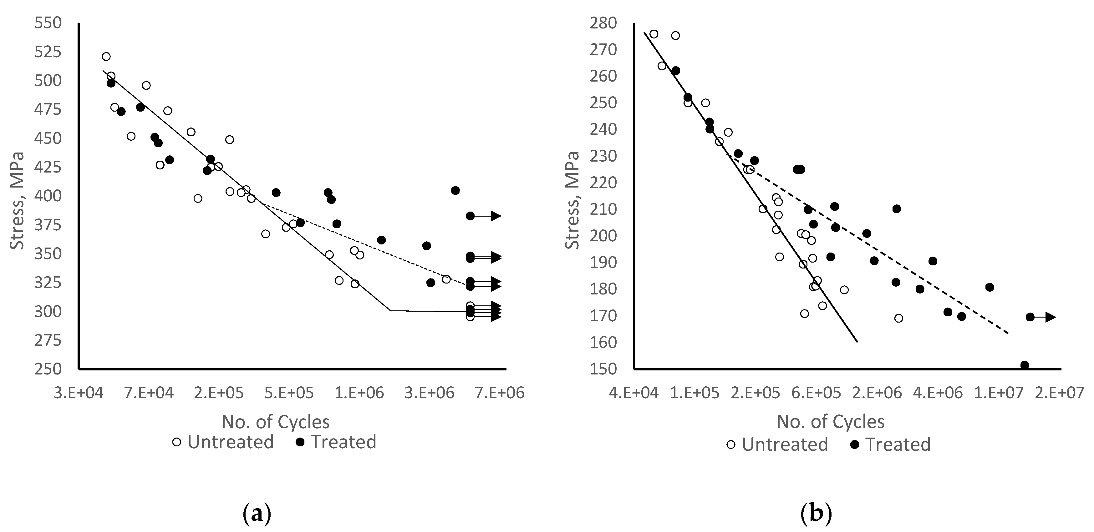
  • Alternating magnetic field treatment led to substantial increase in the fatigue endurance for both alloys, but only minor increases in microhardness and tensile strength were achieved.
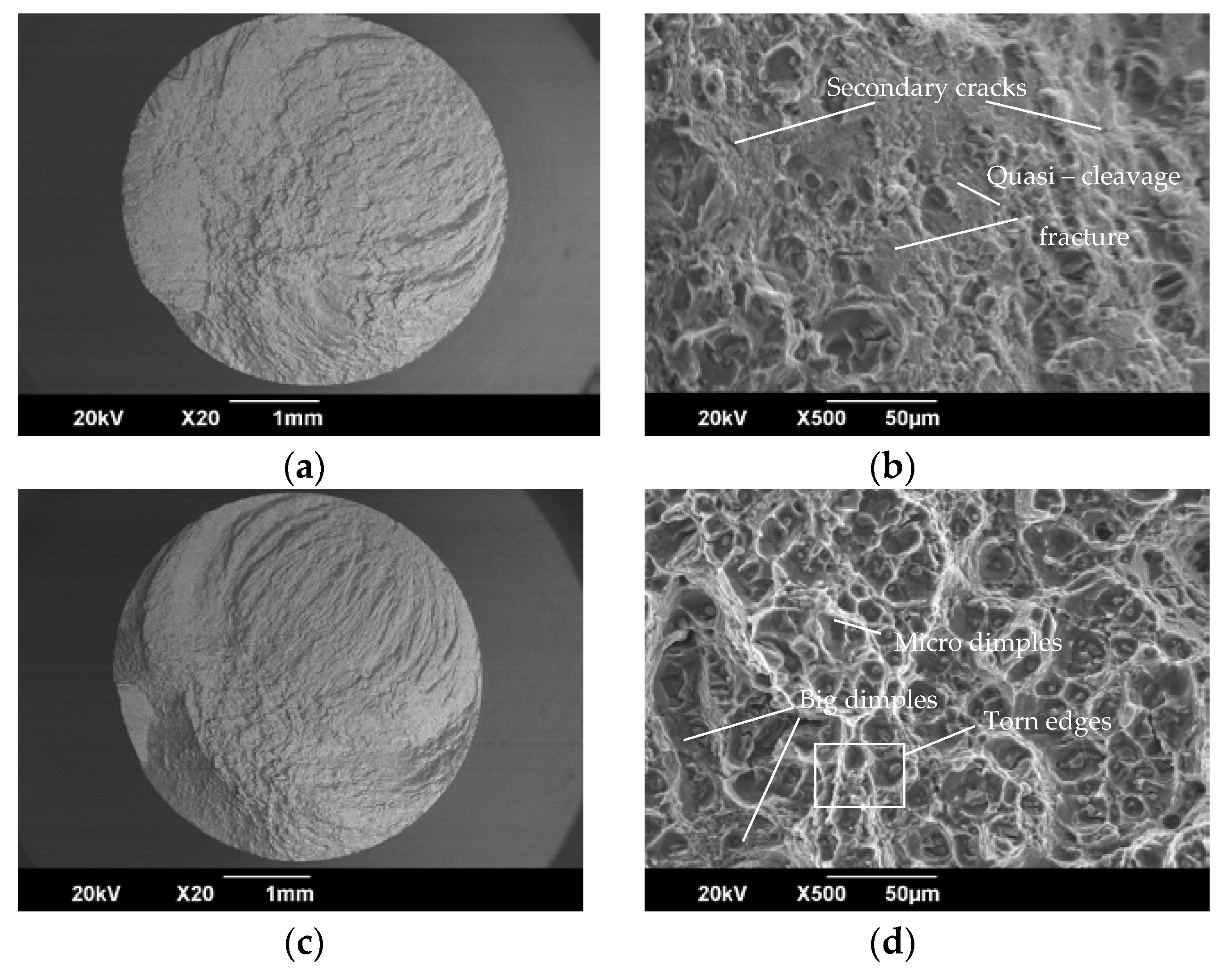
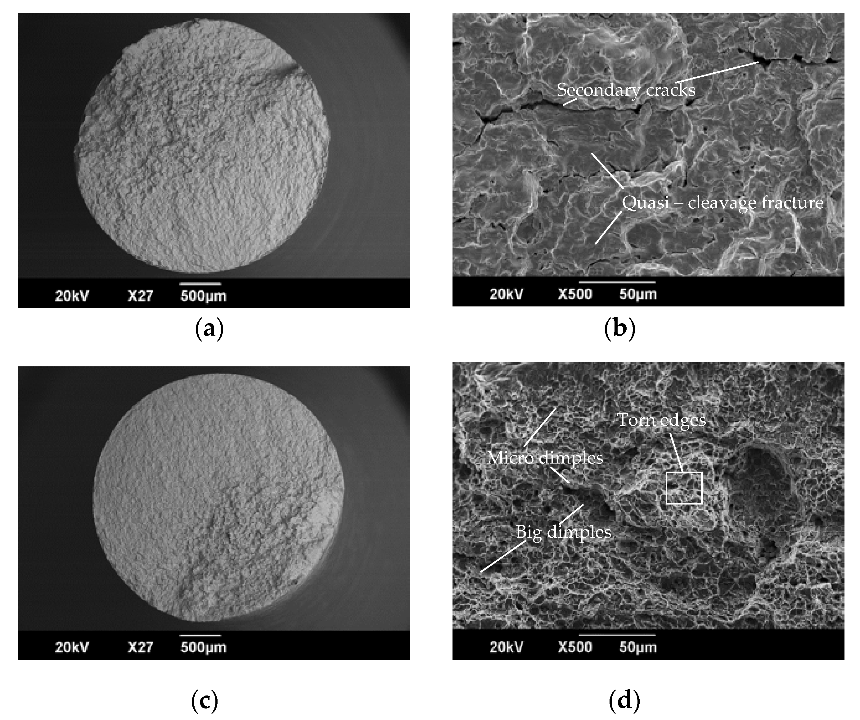
  • SEM analysis indicated ductile fatigue fracture becoming dominant in the treated metals.
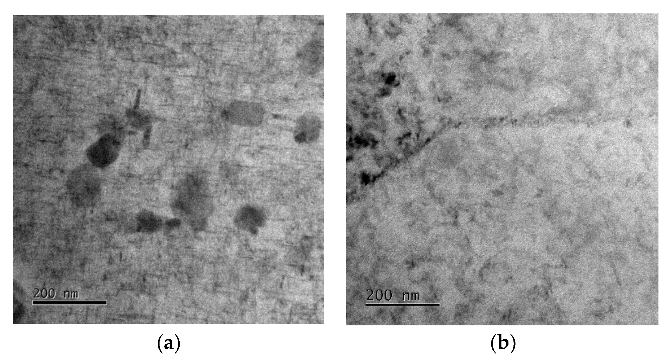
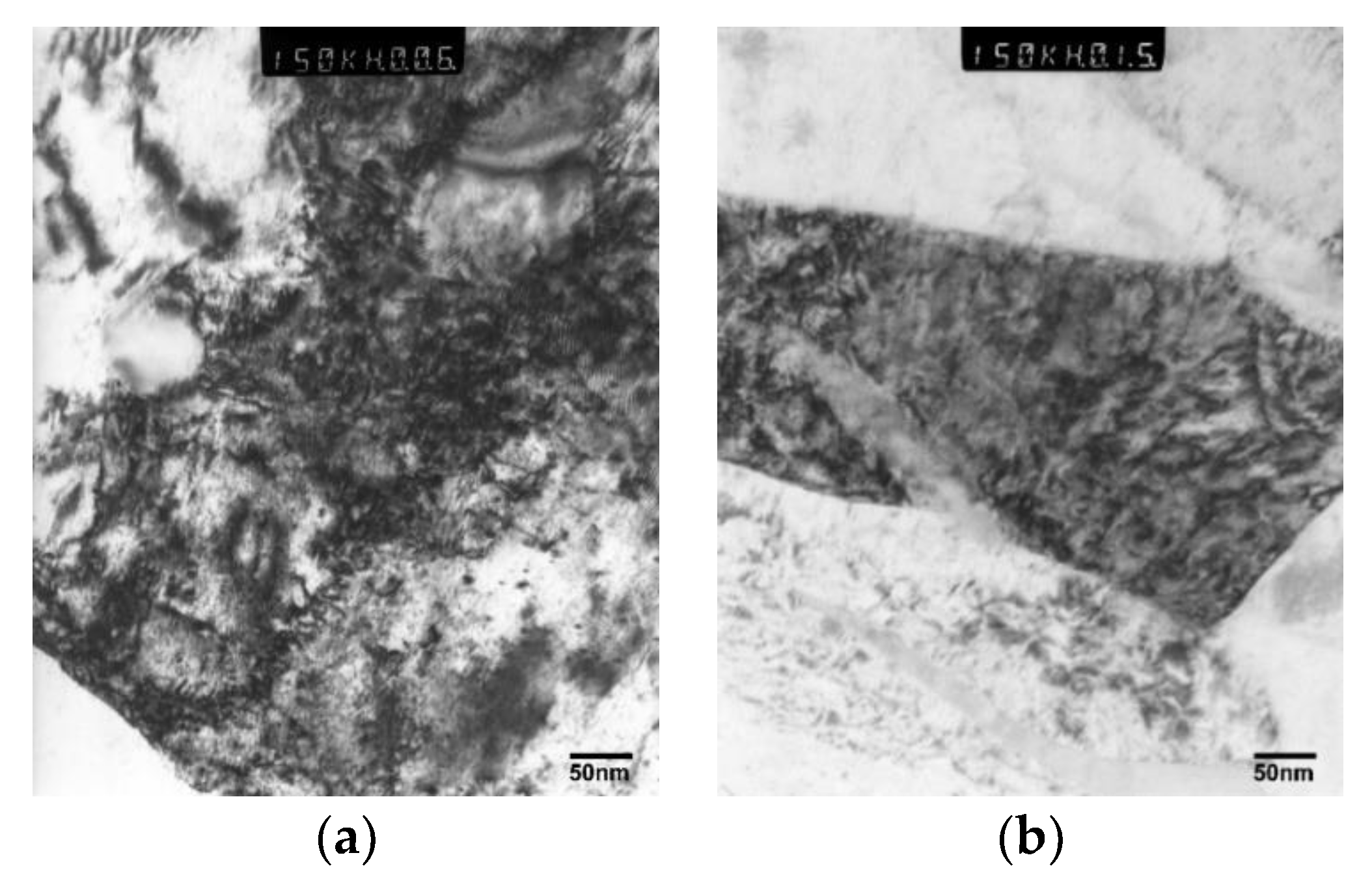
  • TEM analysis indicated that there is a reduction in the dislocation pile-up after treatment for both EN8 steel and AA2014-T6 alloy. In the case of aluminium AA2014-T6, the treatment further generated strengthening precipates in the material.
  • The improvement in fatigue endurance was due to an increase in compressive residual stresses in the near-surface layers of both metals as a result of the treatment. In the case of AA2014-T6 alloy, there was a further contribution from the precipitation of GP zones during the treatment.
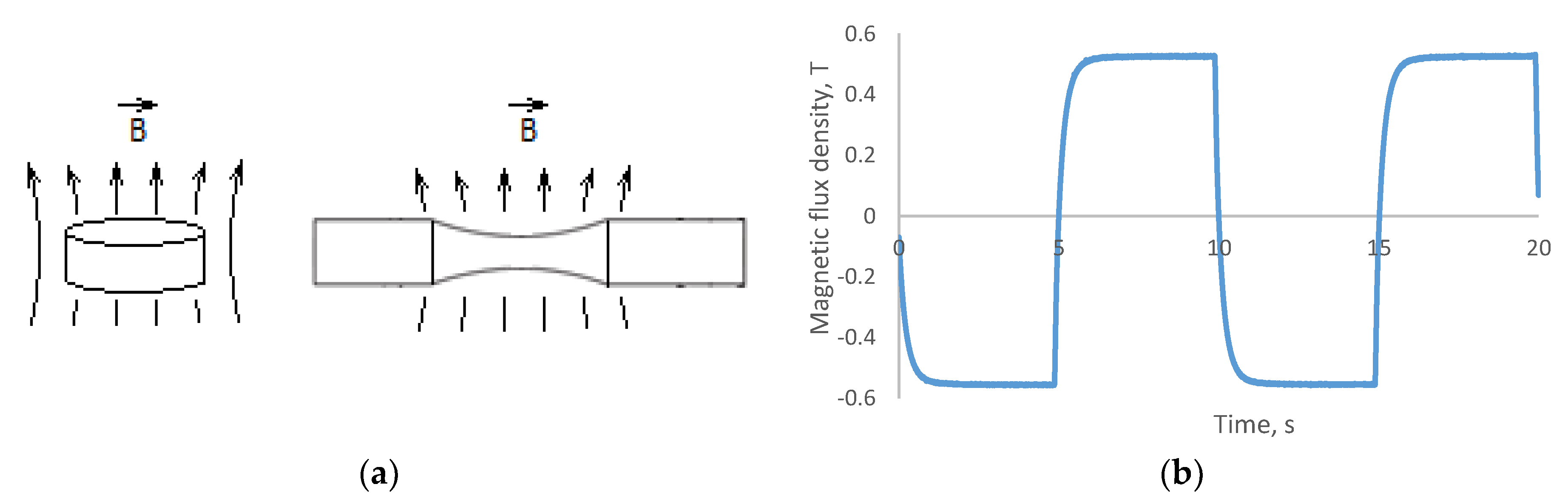
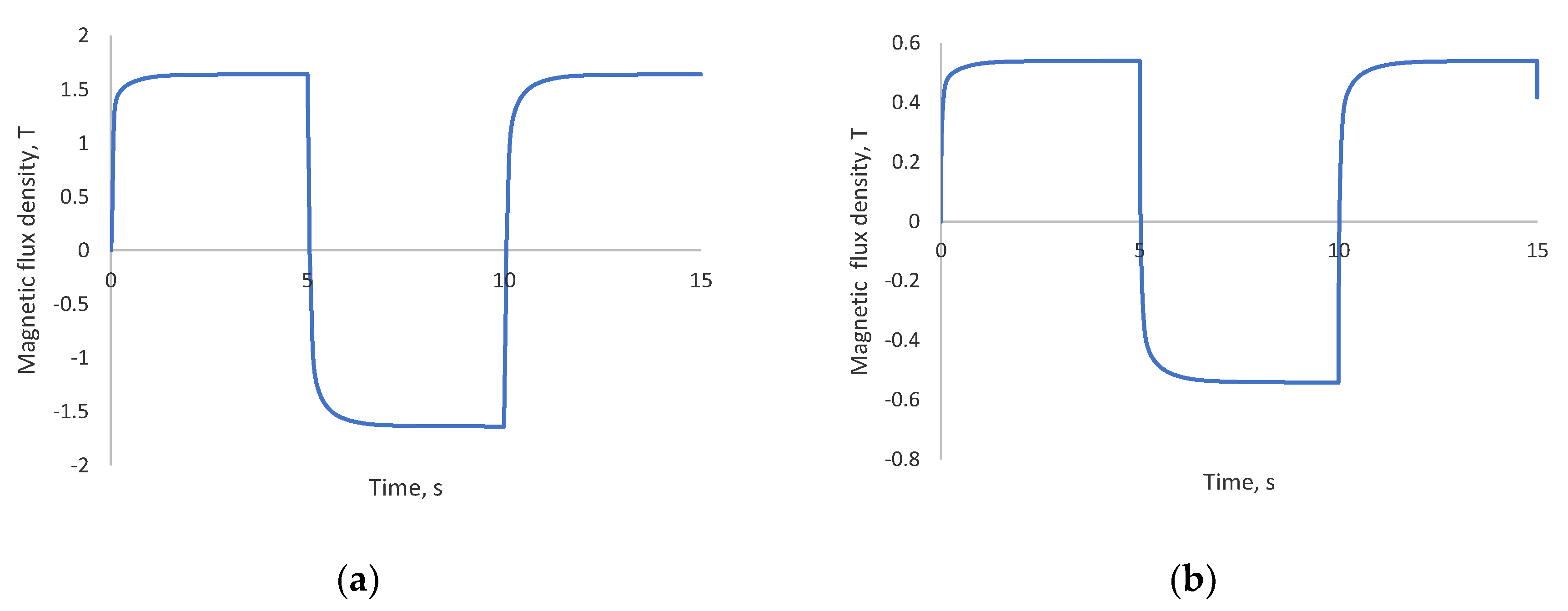
  • The alternating magnetic treatment was accompanied by changes in magnetic field direction and in magnetic polarity and had a non-thermal effect on the two alloys, leading to dislocation depinning and increased mobility of dislocations, giving rise to an increase in the compressive stresses [36].

Author Contributions

Conceptualization, A.B. and A.C.; methodology, S.A., A.B., A.C., D.M. and N.P.; investigation, S.A., A.B., A.C., D.M. and N.P.; resources, A.B., A.C. and D.M.; data curation, S.A. and A.B.; writing—original draft preparation, S.A., A.B. and A.C.; writing—review and editing, S.A., A.B., A.C., D.M. and N.P.; supervision, A.B., A.C. and D.M.; project administration, A.B., A.C. and D.M.; funding acquisition A.B., A.C. and D.M.

Funding

This research was funded by the Marie Curie International Incoming Fellowship scheme within the 7th European Community Framework Programme Grant number PIIF-GA-2010-274324.

Acknowledgments

This research was supported by the Marie Curie International Incoming Fellowship scheme within the 7th European Community Framework Programme Grant number PIIF-GA-2010-274324.

Conflicts of Interest

The authors declare no conflict of interest.

References

  1. Nussbaumer, A.; Borges, L.; Davaine, L. Fatigue Design of Steel and Composite Structures: Eurocode 3: Design of Steel Structures, Part 1-9 Fatigue; Eurocode 4: Design of Composite Steel and Concrete Structures, 2nd ed.; Ernst & Sohn: Hoboken, NJ, USA, 2012. [Google Scholar]
  2. Suryanarayana, C. Experimental Techniques in Materials and Mechanics; CRC Press: Boca Raton, FL, USA, 2011. [Google Scholar]
  3. Suresh, S. Fatigue of Materials; Cambridge University Press: Cambridge, UK, 1998. [Google Scholar]
  4. Anderson, T.L. Fracture Mechanics: Fundamentals and Applications; CRC Press: Boca Raton, FL, USA, 2005. [Google Scholar]
  5. Çelik, A.; Yetim, A.F.; Alsaran, A.; Karakan, M. Effect of magnetic treatment on fatigue life of AISI 4140 steel. Mater. Des. 2005, 26, 700–704. [Google Scholar] [CrossRef]
  6. Lü, B.-T.; Qiao, S.-R.; Sun, X.-Y. Exploration on repairing fatigue damage of steel specimens with magnetic treatment. Scr. Mater. 1999, 40, 767–771. [Google Scholar]
  7. Tang, Y.; Hosoi, A.; Morita, Y.; Ju, Y. Restoration of fatigue damage in stainless steel by high-density electric current. Int. J. Fatigue 2013, 56, 69–74. [Google Scholar] [CrossRef]
  8. Yan, X.; Yang, D.; Liu, X. Influence of heat treatment on the fatigue life of a laser-welded NiTi alloy wire. Mater. Charact. 2007, 58, 262–266. [Google Scholar] [CrossRef]
  9. Fahmy, Y.; Hare, T.; Tooke, R.; Conrad, H. Effects of a pulsed magnetic treatment on the fatigue of low carbon steel. Scr. Mater. 1998, 38, 1355–1357. [Google Scholar] [CrossRef]
  10. Bhat, I.; Muju, M.; Mazumdar, P. Possible effects of magnetic fields in fatigue. Int. J. Fatigue 1993, 15, 93–97. [Google Scholar] [CrossRef]
  11. Conrad, H.; White, J.; Cao, W.; Lu, X.; Sprecher, A. Effect of electric current pulses on fatigue characteristics of polycrystalline copper. Mater. Sci. Eng. A 1991, 145, 1–12. [Google Scholar] [CrossRef]
  12. Roh, J.-H.; Seo, J.-J.; Hong, S.-T.; Kim, M.-J.; Han, H.N.; Roth, J.T. The mechanical behavior of 5052-H32 aluminum alloys under a pulsed electric current. Int. J. Plast. 2014, 58, 84–99. [Google Scholar] [CrossRef]
  13. Hosoi, A.; Nagahama, T.; Ju, Y. Fatigue crack healing by a controlled high density electric current field. Mater. Sci. Eng. A 2012, 533, 38–42. [Google Scholar] [CrossRef]
  14. Jung, J.; Ju, Y.; Morita, Y.; Toku, Y. Effect of pulsed electric current on the growth behavior of fatigue crack in Al alloy. Procedia Struct. Integrity 2016, 2, 2989–2993. [Google Scholar] [CrossRef] [Green Version]
  15. Hosoi, A.; Kishi, T.; Ju, Y. Healing of fatigue crack treated with surface activated pre-coating method by controlling high density electric current. In Proceedings of the 13th International Conference on Fracture, Beijing, China, 16–21 June 2013. [Google Scholar]
  16. Zhou, Y.; Guo, J.; Gao, M.; He, G. Crack healing in a steel by using electropulsing technique. Mater. Lett. 2004, 58, 1732–1736. [Google Scholar] [CrossRef]
  17. Faillace, E.; Chen, I.-W. The effect of a strong magnetic field on age-hardening of iron-chromium alloys. J. Nucl. Mater. 1985, 133–134, 343–346. [Google Scholar] [CrossRef]
  18. Song, Y.; Hua, L. Mechanism of residual stress reduction in low alloy steel by a low frequency alternating magnetic treatment. J. Mater. Sci. Technol. 2012, 28, 803–808. [Google Scholar] [CrossRef]
  19. Cseh, D.; Mertinger, V. X-Ray diffraction measurements of residual stress induced by surface compressing methods. Mater. Sci. Forum 2013, 729, 199–204. [Google Scholar] [CrossRef]
  20. Xie, C.; Yang, S.; Liu, H.; Zhang, Q.; Wang, Y.; Zou, Y. Microstructure and mechanical properties of robot cold metal transfer Al5.5Zn2.5Mg2.2Cu aluminium alloy joints. J. Mater. Process. Technol. 2018, 255, 507–515. [Google Scholar] [CrossRef]
  21. Dudrová, E.; Kabátová, M. Fractography of sintered iron and steels. Powder Metal. Prog. 2008, 8, 59–75. [Google Scholar]
  22. Moeser, M. Fractography with the SEM (failure analysis). In Materials Science Monographs 40: Electron Microscopy in Solid State Physics; Bethge, H., Heydenreich, J., Eds.; Elsevier: Amsterdam, The Netherlands, 2007. [Google Scholar]
  23. Zhou, J.; Xu, S.; Huang, S.; Meng, X.; Sheng, J.; Zhang, H.; Sun, Y.; Boateng, E.A. Tensile properties and microstructures of a 2024-T351 aluminum alloy subjected to cryogenic treatment. Metals 2016, 6, 279. [Google Scholar] [CrossRef]
  24. Li, G.-R.; Cheng, J.-F.; Wang, H.-M.; Li, P.-S.; Li, C.-Q. Influence of a high pulsed magnetic field on the tensile properties and phase transition of 7055 aluminum alloy. Mater. Res. Express 2016, 3, 106507. [Google Scholar] [CrossRef] [Green Version]
  25. Zhang, G.; Zhang, J.; Li, B.; Cai, W. Double-stage hardening behavior and fracture characteristics of a heavily alloyed Al-Si piston alloy during low-cycle fatigue loading. Mater. Sci. Eng. A 2013, 561, 26–33. [Google Scholar] [CrossRef]
  26. Jang, J.I. Estimation of residual stress by instrumented indentation: A review. J. Ceram. Process. Res. 2009, 10, 391–400. [Google Scholar]
  27. Levitin, V.V.; Loskutov, S.V. The effect of a current pulse on the fatigue of titanium alloy. Solid State Commun. 2004, 131, 181–183. [Google Scholar] [CrossRef]
  28. Nie, B.; Zhang, Z.; Zhao, Z.; Zhong, Q. Very high cycle fatigue behavior of shot-peened 3Cr13 high strength spring steel. Mater. Des. 2013, 50, 503–508. [Google Scholar] [CrossRef]
  29. Shimatani, Y.; Shiozawa, K.; Nakada, T.; Yoshimoto, T.; Lu, L. The effect of the residual stresses generated by surface finishing methods on the very high cycle fatigue behavior of matrix HSS. Int. J. Fatigue 2011, 33, 122–131. [Google Scholar] [CrossRef]
  30. Salazar-Guapuriche, M.A.; Zhao, Y.; Pitman, A.; Greene, A. Correlation of strength with hardness and electrical conductivity for aluminium alloy 7010. Mater. Sci. Forum 2006, 519, 853–858. [Google Scholar] [CrossRef]
  31. Murashkin, M.Y.; Sabirov, I.; Kazykhanov, V.; Bobruk, E.; Dubravina, A.; Valiev, R. Enhanced mechanical properties and electrical conductivity in ultrafine-grained Al alloy processed via ECAP-PC. J. Mater. Sci. 2013, 48, 4501–4509. [Google Scholar] [CrossRef]
  32. Tang, G.; Xu, Z.; Tang, M.; Chen, X.; Zhou, H.; Lu, A. Effect of a pulsed magnetic treatment on the dislocation substructure of a commercial high strength steel. Mater. Sci. Eng. A 2005, 398, 108–112. [Google Scholar] [CrossRef]
  33. Klamecki, B.E. Residual stress reduction by pulsed magnetic treatment. J. Mater. Process. Technol. 2003, 141, 85–94. [Google Scholar] [CrossRef]
  34. Free BH Curves. Available online: https://magweb.us/ (accessed on 5 January 2019).
  35. Baranov, Y.V.; Troitskii, O.; Avraamov, Y.S.; Shlyapin, A. Physical bases of electric-pulse and electroplastic treatments and new materials. Chap 2001, 1, 56–77. [Google Scholar]
  36. Troitskii, O.; Spitsyn, V.; Sokolov, N.; Ryzhkov, V. Application of high-density current in plastic working of metals. Phys. Status Solidi A 1979, 52, 85–93. [Google Scholar] [CrossRef]
  37. Cai, Z.; Huang, X. Residual stress reduction by combined treatment of pulsed magnetic field and pulsed current. Mater. Sci. Eng. A 2011, 528, 6287–6292. [Google Scholar] [CrossRef]
  38. Tang, F.; Lu, A.L.; Mei, J.F.; Fang, H.Z.; Luo, X.J. Research on residual stress reduction by a low frequency alternating magnetic field. J. Mater. Process. Technol. 1998, 74, 255–258. [Google Scholar] [CrossRef]
  39. Oliferuk, W.; Gadaj, S.P.; Grabski, M.W. Energy storage during the tensile deformation of armco iron and austenitic steel. Mater. Sci. Eng. 1985, 70, 131–141. [Google Scholar] [CrossRef]
  40. Molotskii, M.; Fleurov, V. Spin effects in plasticity. Phys. Rev. Lett. 1997, 78, 2779. [Google Scholar] [CrossRef]
  41. Hayashi, S.; Takahashi, S.; Yamamoto, M. Plastic deformation of nickel single crystals in an alternating magnetic field. J. Phys. Soc. Jpn. 1968, 25, 910. [Google Scholar] [CrossRef]
  42. Hayashi, S.; Takahashi, S.; Yamamoto, M. Magneto-plastic effect in nickel single crystals. J. Phys. Soc. Jpn. 1971, 30, 381–387. [Google Scholar] [CrossRef]
  43. Hayashi, S. Magneto-plastic effect in nickel and nickel-cobalt alloy single crystals. J. Phys. Soc. Jpn. 1972, 32, 949–957. [Google Scholar] [CrossRef]
  44. Tang, F.; Lu, A.L.; Fang, H.Z.; Mei, J.F. Effect of magnetic treatment on magnetostrictive behaviour of HT70 steel. Mater. Sci. Eng. A 1998, 248, 98–100. [Google Scholar] [CrossRef]
  45. Molotskii, M. Possible mechanism of the magnetoplastic effect. Sov. Phys. Solid State 1991, 33, 1760–1761. [Google Scholar]
  46. Molotskii, M. Negative magnetoplastic effect in nonmagnetic crystals. Phys. Solid State 1993, 35, 5–7. [Google Scholar]
  47. Molotskii, M.I. Theoretical basis for electro-and magnetoplasticity. Mater. Sci. Eng. A 2000, 287, 248–258. [Google Scholar] [CrossRef]
  48. Polmear, I. Light Alloys: From Traditional Alloys to Nanocrystals; Elsevier: Amsterdam, The Netherlands, 2005. [Google Scholar]
Figure 1. Scheme of treatment for samples (a) and the magnitude of the magnetic field during treatment (b).
Metals 09 00984 g001
Figure 2. S–N curves for untreated and treated EN8 Steel (a) and AA2014-T6 (b); data for samples where the test was stopped without sample fracture are marked as •→.
Metals 09 00984 g002
Figure 3. SEM images of EN8 fractured surface for untreated (a,b) and treated (c,d).
Metals 09 00984 g003
Figure 4. SEM images of AA2014-T6 fractured surface for untreated (a,b) and treated (c,d).
Metals 09 00984 g004
Figure 5. TEM images of untreated (a) and treated (b) EN8.
Metals 09 00984 g005
Figure 6. TEM images of untreated (a) and treated (b) AA2014-T6.
Metals 09 00984 g006
Figure 7. Schematic view of a quartered geometrical model of magnetizer with sample: 1—sample, 2—core; 3—winding (consists of 70 turns), 4—air, 5—spacer.
Metals 09 00984 g007
Figure 8. Calculated magnetic flux density in central point of sample: (a) EN8, (b) AA2014-T6.
Metals 09 00984 g008
Figure 9. Calculated eddy currents on cylindrical surface of samples: (a) EN8, (b) AA2014-T6.
Metals 09 00984 g009
Table 1. Chemical composition of EN8 Steel.
CompositionFeCMnMoPSiS
Percentage (wt.%)Bal.0.36–0.440.6–1.00.150.050.1–0.40.05
Table 2. Chemical composition of 2014-T6 aluminium alloy.
CompositionAlSiFeCuMnMgCrZnTiOthers
Percentage (wt.%)Bal.0.5–1.2< 0.73.9–5.00.4–1.20.2–0.80.10.250.150.15
Table 3. Mean (M) and mean-square deviation (MSD) results of microhardness, tensile strength, conductivity and RS.
Sample ConditionMicrohardness, HVUTS, MPaConductivity, MS/mRS, MPa
MMSDMMSDMMSDMMSD
EN8 SteelUntreated26412.388618.1N/A−26871.7
Treated2707.691415.5−32039
Aluminium alloy 2014-T6Untreated1534.45412.522.900.0074−9940.5
Treated1582.85503.622.380.0046−13020.9
Table 4. Physical properties of components of the model.
PropertyCore (Steel)Spacer (Steel)Winding Wire (Copper)EN8 SampleAA2014-T6 SampleSurrounding Air
Conductivity, MS/m10105610230
Relative permeabilityB–H curve *B–H curve *1B–H curve *11
* The magnetic flux density vs. magnetic field strength (B–H) curve for steel was taken from [34].

