Article

Surface Integrity of Laser Beam Welded Steel–Aluminium Alloy Hybrid Shafts after Turning

1
Laser Zentrum Hannover e.V., Hollerithallee 8, 30419 Hanover, Germany
2
Institute of Production Engineering and Machine Tools, Leibniz University Hannover, An der Universität 2, 30823 Garbsen, Germany
3
Institute of Dynamics and Vibration Research, Leibniz University Hannover, Appelstraße 11, 30167 Hannover, Germany
4
Institute of Materials Science, Leibniz University Hannover, An der Universität 2, 30823 Garbsen, Germany
*
Author to whom correspondence should be addressed.
Metals 2019, 9(2), 134; https://doi.org/10.3390/met9020134
Submission received: 18 December 2018 / Revised: 15 January 2019 / Accepted: 21 January 2019 / Published: 26 January 2019

Abstract

:
The demands for high-performance solid components are constantly increasing. The reason for this development are the steadily growing requirements such as weight reduction, higher resistance to load stresses, and more functional integration. By using material compounds, for example high-strength steel and aluminium alloy, hybrid massive components, whose properties are specially adapted to the specific application, can be manufactured. The first challenge is the joining of two dissimilar materials like steel and aluminium alloy by laser beam welding. In particular, the formation of hard and brittle intermetallic phases (IMP) has a high influence on the mechanical properties of the joining zone. The second challenge is to examine the machinability of such dissimilar compounds. The machining process is mandatory in order to reach an adequate level of accuracy of shape and dimensions. Furthermore, the functionalization of the hybrid compounds will be realized with the machining process where required surface roughness and lifetime-determining residual stresses are adjusted. Connections between induced residual stresses and material properties have been investigated. A significant influence of machining parameters on the surface and subsurface properties is evident. In particular, the cutting edge rounding has a deep impact on the residual stresses as well as on surface roughness.

1. Introduction

The production of environmentally-friendly components is a major challenge nowadays. In particular, the reduction of the CO2 emissions for applications like powertrain components, e.g., drive shaft or motor shaft, is a major topic. Lightweight design of vehicle parts is one possibility to reduce CO2 emissions. Therefore functionally adapted components must be designed in order to become smaller and lighter. Consequently, monolithic material is not sufficient any more, so there is a demand for tailored hybrid parts consisting of more than one material. Those tailored hybrid parts have to pass through a process chain. Within the framework of the Collaborative Research Center 1153 “Tailored Forming”, the potentials for hybrid solid components are investigated on the basis of new tailored manufacturing processes using joined semi-finished products. Steel–aluminium alloy compounds show great potential in terms of weight reduction by replacing parts of the steel component with aluminium alloy. The density of aluminium alloy amounts to just 33% of the density of steel. Thus, the hybrid design leads to a weight reduction. Here, the joining of dissimilar blanks takes place either by friction welding or by laser beam welding. The big challenge for the thermal joining of steel and aluminium alloys is the formation of intermetallic phases (IMP) in the liquid state. IMP (especially aluminium-rich) are characterized by high hardness values and a low ductility [1,2,3], which result in reduced resistance towards impact or mechanical loads compared to the base materials. Low energy-joining processes are suitable for a reduction of the formation of IMP, an example is laser beam brazing in butt joint configuration for 1 mm sheets of steel and aluminium alloy with aluminium wire. The avoidance of a molten contact between the two materials and realization of the connection only based on diffusion reduces the width of the area with IMP to 2 µm [4]. Laser beam welding-brazing IMP layers between 4 µm and 22 µm were observed [5]. For laser beam welding, the prevention of contact of the two melts is not possible, but a reduction of the IMP zone increases strength. For lap joints strength up to 75% of the strength of the aluminium alloy can be achieved in tensile shear tests [6]. With in-process control, a consistent penetration depth for lap joints with relatively low [7] as well as high material thicknesses is achievable [8]. The strength of the joint mainly depends on the content of molten aluminium, which allows an in-process control [8]. Both materials show a similar flow pattern despite their very different physical properties. A simulative investigation on the formation pf porosities for laser beam welding of both, steel and aluminium alloys, can be found in Huang et al. [9]. Consequently, laser beam welding is an appropriate joining process due to its reduced heat influence, the resulting narrow welds and a low post-processing effort. Thus, semi-finished products for the manufacturing of tailored hybrid shafts with graded properties can be produced efficiently. In the current state of the art there are so far no scientific studies regarding the improvement of the material bond by this method. Therefore, laser beam welding in combination with a subsequent/following machining process is investigated in the present work with regard to improving the bonding strength of the joining zone and the residual stresses.
Furthermore, in the process chain there is for machining a demand to reach an adequate level of accuracy of shape and dimension. In practice, optimal process parameters depend on the material that is machined. Hence, the recommended process variables for steel differ from those of aluminium alloy. The reason for that are different material properties, which lead to a different machining behaviour. One big challenge is the identification of suitable process parameters for machining steel and aluminium alloy with material-adapted process parameters in order to reach the requirement for dimensional and shape tolerances and especially mandatory surface roughness. Moreover, due to different expansion coefficients of the materials, residual stresses are caused after the joining process during cooling, which are altered by subsequent machining of the component. The residual stress modification by the machining process has a deep impact on the lifespan of hybrid components [10,11,12]. However, the influence of machining on subsurface properties in the joining zone of laser beam-welded shafts has not been investigated so far. Therefore, in this paper the machinability of a steel-aluminium alloy joint and the influence of process parameters on surface roughness and residual stress is examined.

2. Materials and Methods

2.1. Materials

The materials used are shown in Table 1 and Table 2. The samples are round bars with a diameter of 30 mm and a length of 50 mm. The joining surfaces for butt joints have a quality (Rz [EN AW-6082] = 31.7 ± 7.3 µm and Rz [SAE5120] = 43.3 ± 12.1 µm) which is good enough to get close to a zero gap.

2.2. Laser Beam Welding

The experimental setup for laser beam welding of the shafts includes a diode-pumped solid-state disk laser (TruDisk 16002, TRUMPF GmbH + Co. KG, Ditzingen, Germany) with a maximum power output of 16 kW. The laser beam power is fed into the welding head by an optical fibre with 200 µm diameter. With the optics of the welding head ([YW52, Precitec GmbH & Co. KG, Gaggenau, Germany] focal length of the collimation lense fC = 150 mm, focal length of the focusing lense fF = 300 mm), the resulting focal diameter is 400 µm. The welding parameters are a laser beam power of PL = 6.0 kW and a welding speed of vf = 1.85 m/min. There is a 10° angle of incidence to avoid damage to the optical elements due to back reflection. The samples are clamped with a hydraulic pressure of 150 bar. The focal point is positioned 0.55 mm on the steel side. The focal z-position is 4 mm below the surface. The laser welding parameters are chosen from the best mixing ratio regarding the mixing ratio (position of the focal point) and the maximum available power output at this time limited by safety regulations. The welding speed used produced a small amount of spatters compared to lower welding speeds and a higher weld depth compared to higher welding speeds.
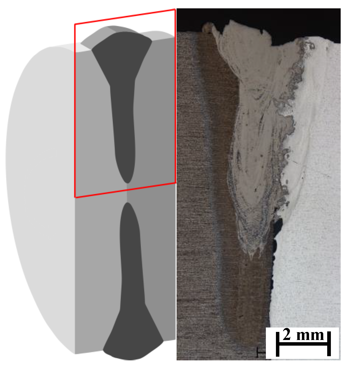
The sample geometries with the weld in cross sections during and after welding are shown in Figure 1 in a schematic drawing. As can be seen the weld root does not reach the center of the sample. On the one hand, due to this there is no stirring up of the already solidified weld; on the other hand, the reduced connection area has no influence on the measurements in the paper.

2.3. Cutting

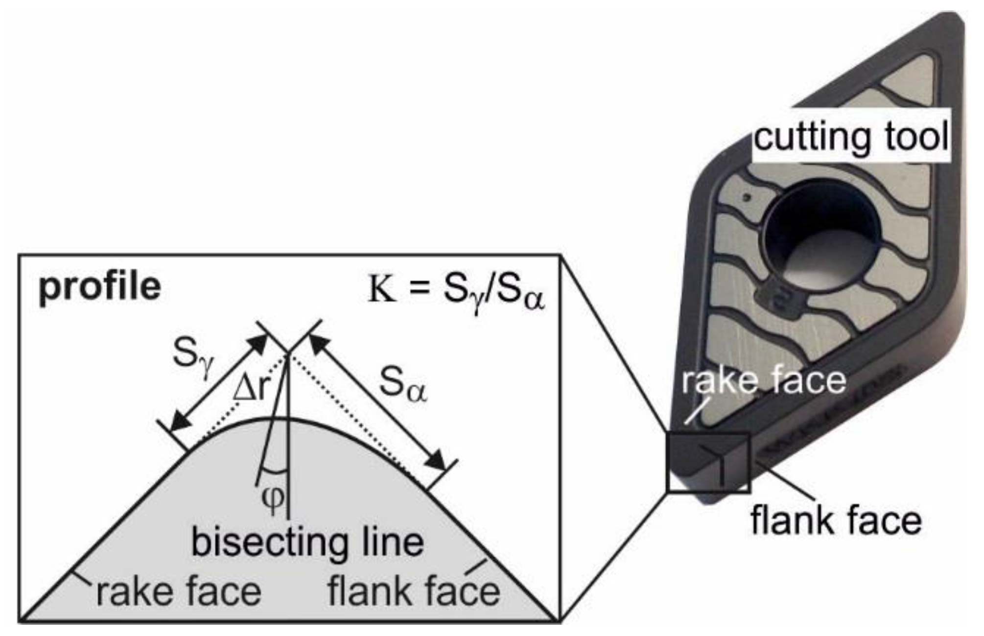
This investigation is part of an effort to determine the effects of cutting edge rounding and component hardness on surface generation in turning of steel–aluminium alloy hybrid shafts. Samples prepared with different cutting edge roundings were used in order to investigate the influence on the subsurface residual stresses. The characterization of the cutting tool micro geometry is a fundamental requirement in order to investigate its influence on machining processes systematically. The radius rβ of the rounded cutting edge is not sufficient to characterize different forms of the cutting edge microgeometry. Hence, the parameters Sγ, Sα and the form factor κ have been defined in order to describe such cutting edge geometries (Figure 2). The cutting edge segments Sα and Sγ are defined as the distance between the separation point of the cutting edge rounding and the tool tip of an ideal sharp cutting edge at flank face and rake face, respectively. The form factor κ specifies the orientation of the rounding at the cutting edge [15].
The cutting edge preparation was carried out by means of a brushing robot (KUKA, Augsburg, Germany). Thereby, indexable inserts with a rhombic tool that included angle of ε = 93° (DNMA-150612-WAK20, Walter, Tübingen, Germany) were prepared with a preconditioned SiC-brush with a grain diameter of 240 µm. Previously defined cutting edge microgeometries were then produced by the brushing process. All produced cutting edge microgeometries were measured optically after preparation (GFM MikroCAD, (LMI Technologies GmbH, Teltow, Germany) for digital fringe projection) and characterized consistently using Sγ, Sα and κ via the software “Cutting Edge Effective” (version 1.0.0.0, IFW, Garbsen, Germany). This software has been developed at the Institute of Production Engineering and Machine Tools (IFW) for evaluating measured microgeometries. The prepared inserts were then used in cutting experiments.
Table 3 summarizes the process parameters of the cutting operation used in this investigation. A two-factor design of experiment was used to determine the effects of cutting edge geometry and cutting direction on the process forces and subsurface residual stresses. The examined factors were therefore varied in two steps.
Longitudinal turning was conducted on the Gildemeister CNC-universal lathe CTX 420 in two different cutting directions (aluminium alloy to steel, steel to aluminium alloy) and two different cutting edge microgeometries. Both, depth of cut and feed were held constant at a value of ap = 0.2 mm and f = 0.05 mm, respectively. The welded steel–aluminium alloy shaft was clamped into place on one end instead of between two tool tips to maximize rigidity and minimize runout. The length of cut for each experiment was 77 m, and it was kept small in order to minimize the effect of tool wear on subsurface and surface properties. During the cutting operation, process forces were measured with a Kistler 9129AA three-component dynamometer. Correlations between process parameters, cutting forces and subsurface properties were analyzed.

2.4. Microstructure

In metallographic cross sections, the weld is visible after etching. In Figure 3, a metallographic cross section is shown exemplarily. The weld depth is about 8.3 mm. The steel base material is on the left side and the aluminium alloy base material is the lighter one on the right side. The weld metal and the base material on the left side (steel) are separated by a clear boundary. The boundary between the weld metal and the aluminium alloy base material is less sharp and has a small area characterized by the mixing of the two metals. In the steel material the heat affected zone (HAZ) is clearly visible, and that in the aluminium alloy is comparatively smaller. Due to the formation of the IMP, several cracks arise.
In the further procedure metallographic cross sections of the steel-aluminium alloy samples machined with different cutting edge roundings were prepared. Hardness measurements according to Vickers (HV0.1) were carried out. The results of the analyzes of the microstructure were compared to the residual stress and surface measurements that are discussed in Section 3.

2.5. Residual Stress Measurement

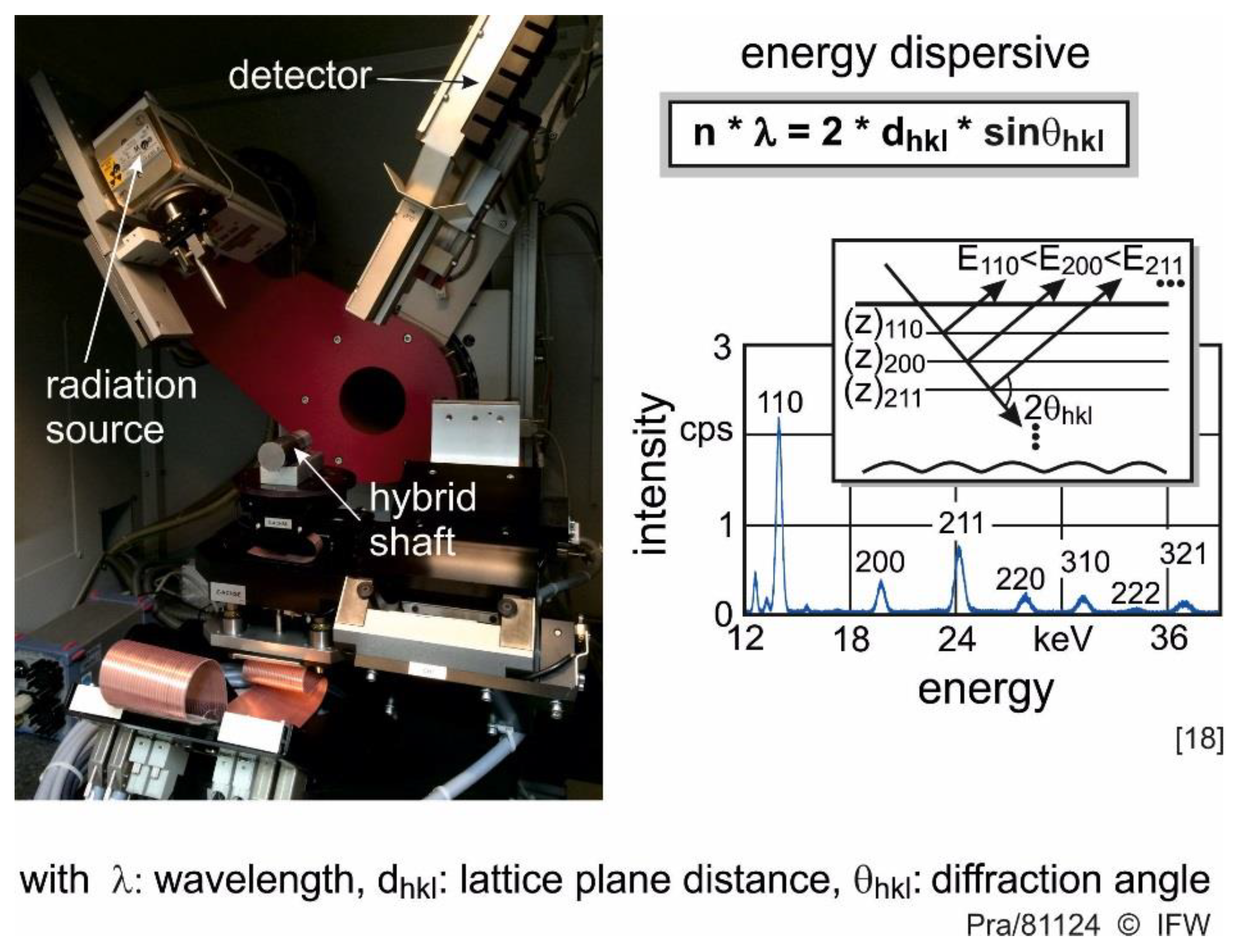
The X-ray diffraction (XRD) sin²ψ method for lattice strain measurement is based upon the well-established Braggs’s law [16]. One condition in order to analyze the modification of residual stress depth profiles by the machining process is their non-destructive measurement. Energy-dispersive residual stress determination is an appropriate method to identify non-destructively residual stress depth profiles. The information depth is certainly limited depending on the measured material. In steel shafts, a residual stress depth information up to 35 µm and in aluminium alloy up to 300 µm are possible. However, these information depths are sufficient to capture changes in residual stress depth profiles [17,18].
In the energy-dispersive measurement, the sample is irradiated with polychromatic (white) X-radiation (Bremsstrahlung). The diffracted radiation is energy detected dispersively at a fixed angle 2θ, which remains constant throughout the measurement. Thus, all interference lines are simultaneously determined in one diffraction spectrum. The detected diffraction peaks are a function of wavelength λ or photon energy Eph (cf. Figure 4). The various interference lines are distinguished by different energy levels in the spectrum. These can be attributed to different penetration depths. In steel shafts, depth information in the range of 0.8 μm to about 35 μm is obtained.
In this study, the energy-dispersive X-ray stress investigations were carried out with white radiation from a W anode on a Seifert XRD 3003 ETA diffractometer, (Agfa NDT Pantak Seifert GmbH & Co KG, Ahrensburg, Germany). Measurements were carried out with a ∅ 2 mm point collimator. The sin²ψ method was applied in a tilting angle between −45° and +45° on the basis of equal distant sin²ψ distribution. The fixed Bragg angle applied for the energy dispersive measurement is θ = 20°.

2.6. Surface Measurements

In order to measure the surface of the machined samples, an optical surface measurement device (Alicona Infinity Focus XL200 G5, Alicona Imaging GmbH, Raaba, Austria) was used. This method is based on focus variation. An area of the welded zone of 10 mm × 2.5 mm was measured and analyzed using the software package “µsoft analysis premium 7.1” by Digital Surf SARL. The evaluation of the average surface roughness Rz was conducted at four different positions near the welded zone.

3. Results and Discussion

3.1. Microstructure

Figure 5 shows a metallographic cross section of a steel-aluminium alloy weld sample. The aluminium alloy is the brighter material in the lower side of the picture. The mixing of both materials is clearly visible. Therefore, the appearance of cracks is obvious, which results from the formation of IMP. The hard and brittle IMC are mainly composed of FeAl3 and Fe2Al5 in the aluminum-rich areas [1,2,3]. An overview of the investigations about IMP can be found for different welding processes in [19].
In Figure 6 the whole turned surface (rotated and extended view) is represented in a metallographic cross section [20].
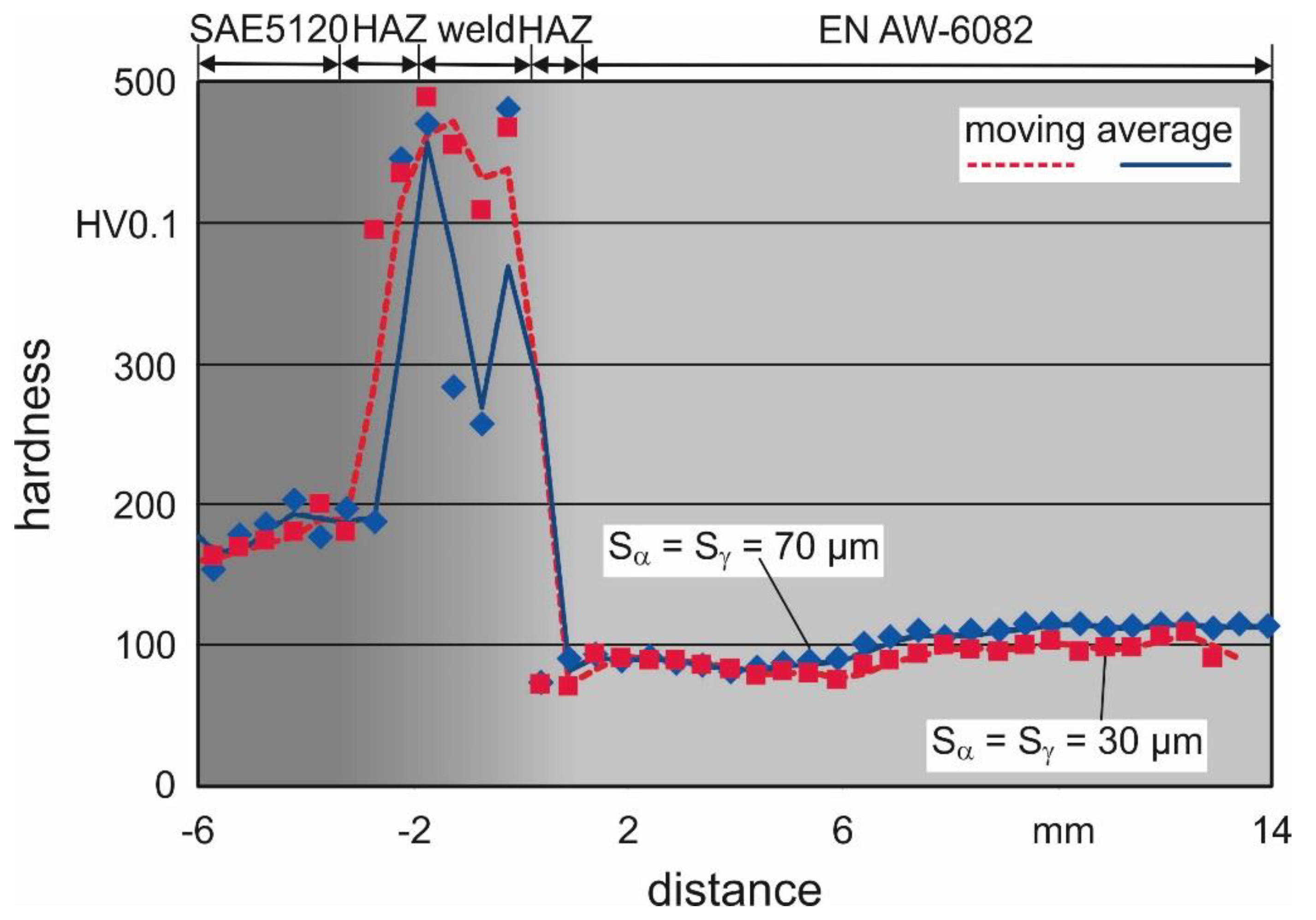
Hardness HV0.1 was detected for two laser beam welded and turned samples (exemplarily indentations from hardness measurements are visible in Figure 6). Figure 7 shows the results of the hardness measurements (100 µm below the surface according to the standard DIN EN ISO 6507-1 [21]) with a distance between the measurement points of 500 µm. The hardness profile reflects the different hardnesses of the two base materials and the HAZ, the most interesting area is the weld metal. The hardness level in the weld metal is unsteady. This effect occurs mainly due to the formation of IMP, which are characterized by high hardness and low ductility. The high stresses in the weld metal lead to the occurrence of cracks, which decrease the hardness values. In the area of the base materials, the hardness for each material reaches a consistent value. The cutting edge rounding has no influence on the hardness level.

3.2. Machining Results

The examinations between the different cutting directions for the steel-aluminium alloy weld revealed worse quality for the cutting direction from SAE5120 into EN AW-6082 in the machining process. The reason is that the clamping of the shaft with the aluminium alloy side is unfavourable due to the lower strength of this material. This leads to slight chatter vibrations during processing. Therefore, in the following chapter only the cutting direction EN AW-6082 into SAE5120 is analyzed. The influence of the cutting edge geometry on process forces, residual stresses, and surface roughness is discussed.

3.2.1. Cutting Forces

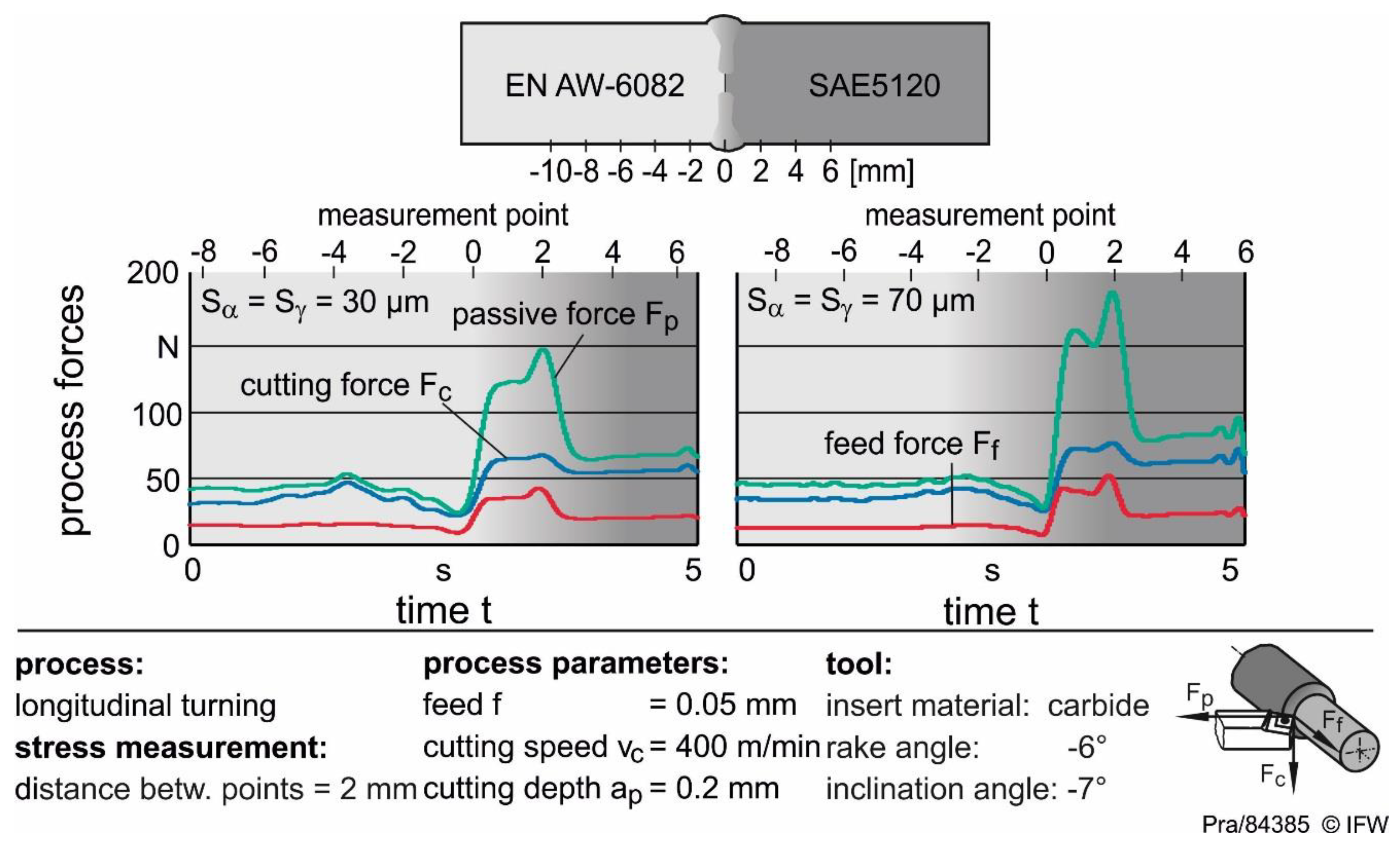
In Figure 8 the influence of different cutting edge geometries on the cutting forces during turning of a steel–aluminium alloy welded shaft is shown.
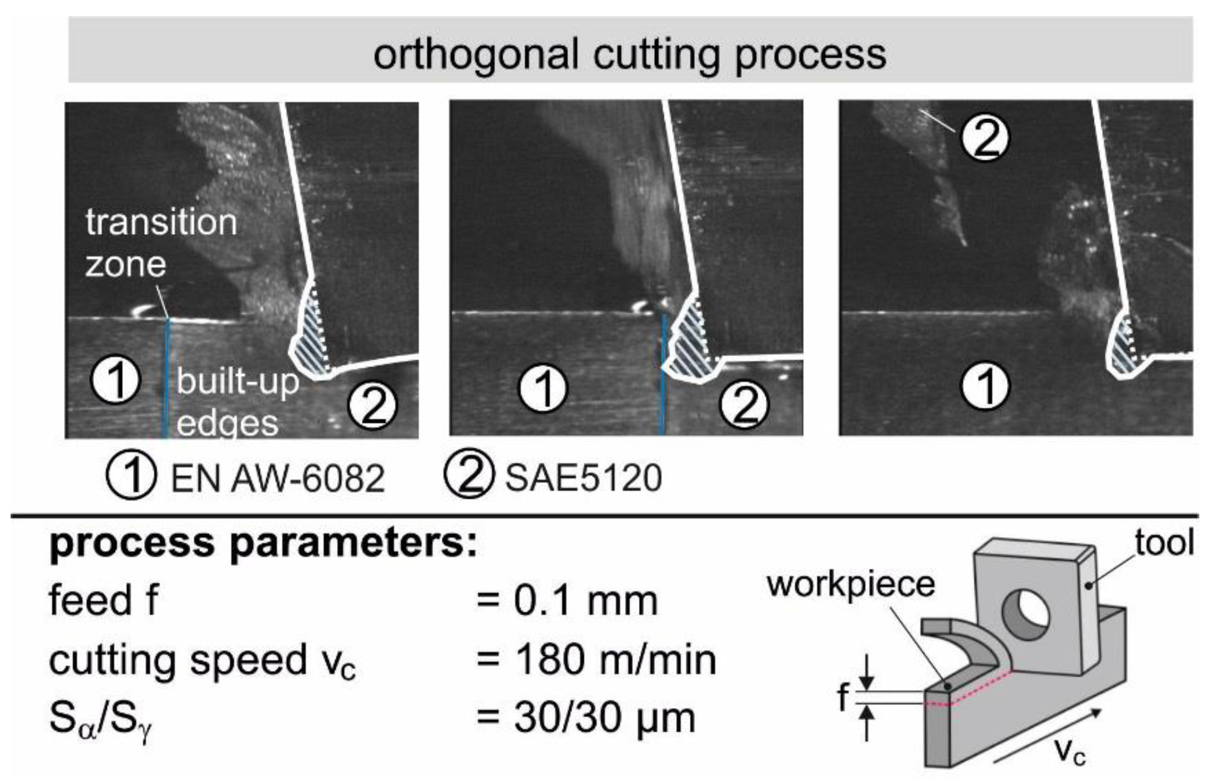
It is obvious that the cutting forces increase in the HAZ of SAE5120 due to the higher hardness. In particular, the passive forces increase appreciably regardless of the cutting edge geometry. The increase can be explained with the change of the material properties during cutting. Notably, the hardness and the tensile strength are significantly higher in comparison to the base material in the weld and the HAZ of the steel SAE5120. In addition, a decrease of hardness in the HAZ of the aluminium alloy, causes a decrease of the process forces in this zone. Hardness measurements, as shown as in Figure 7 confirm the observed behaviour. Variations of process forces in the weld metal indicate the presence of IMP. This leads to a different machining behaviour in the material transition zone. Despite the different material properties of steel and aluminium alloy, the process forces are only slightly higher during cutting, especially for the smaller cutting edge roundings. In order to examine the built-up edges high-speed pictures during orthogonal cutting were carried out (Figure 9). The reason for that is the occurrence of built-up edges during the cutting of aluminium alloy. This built-up edge leads to a geometrical modification of the actual cutting edge rounding. Therefore, the rake angle γ is shifted into positive direction by which the process forces decrease. Built-up edges have been noticed at larger cutting edge roundings, too.
Cutting edge tool geometry shows a significant influence on the passive forces in the HAZ. Independent of the used tool the process forces decrease in the HAZ of aluminium alloy and increase in the HAZ of steel. Thus, the mechanical loads in the corresponding zones are lower in the aluminium alloy and higher in the steel area, which indicate differences in the residual stresses in both materials. Furthermore, a large cutting edge rounding of Sα = Sγ = 70 µm leads to an increase of the cutting forces, especially in the HAZ of the hybrid shaft. Feed force and cutting force show no significant impact by changing tool geometry, but in the joining zone, a rise of these forces should not be neglected. A greater cutting edge rounding leads to an increase of the passive force due to a greater contact length between component and tool. Consequently, the chip thickness increases and more material is transformed in front of the cutting edge. Besides, dislocation movements, induced by the material transformation, lead to an increase of hardness. Hence, the process forces increase. As a result, higher process forces, especially passive forces Fp, are noticed.

3.2.2. Residual Stress Measurement

In Figure 10 the effect of different cutting edge roundings on residual stress especially in the area of the joining zone of the steel–aluminium alloy welded shaft is shown. The residual stress was analyzed parallel to the surface for different depths (0.8–20.0 µm). Therefore, the energy dispersive residual stress measurements were conducted at nine different positions (pos. –10 mm until 6 mm), both in base material as well as in the weld. The measurements were carried out both in axial and tangential direction. The qualitative course of the residual stresses is similar in both directions. The residual stress amounts only differ quantitatively. Because of higher compressive residual stresses in the transversal direction only these are presented below. Corresponding to the cutting force measurement, the transversal residual stresses shift into compressive direction in the HAZ of the base material of SAE5120. In the HAZ of EN AW-6082 there is also stronger compressive residual stress observable but it is small compared to the HAZ in SAE5120. As IMP in the weld metal cannot be excluded, an altered cutting behaviour and thus changes in the residual stresses are expected. This requires further structural analysis to investigate the influence of IMP on machinability. A comparison of the residual stress values at different surface distances of the component shows that the qualitative course remains almost the same. With increasing surface distance only the absolute values, especially in the joining zone as well as in the SAE5120 field shift into less compressive direction towards zero.
Due to higher passive forces Fp when using 70 µm rounded cutting edges, the surface near compressive residual stresses are significantly higher. The residual stresses show a steep depth gradient but they are still higher in the HAZ of the steel for the larger cutting edge rounding than those induced with the smaller cutting edge rounding. A reduction of cutting speed leads to a reduction of the process forces. Lower passive forces lead to lower compressive residual stresses. However, the course of the residual stresses remains unchanged by varying the cutting speed, which is why a more detailed description is omitted.

3.2.3. Surface Measurement

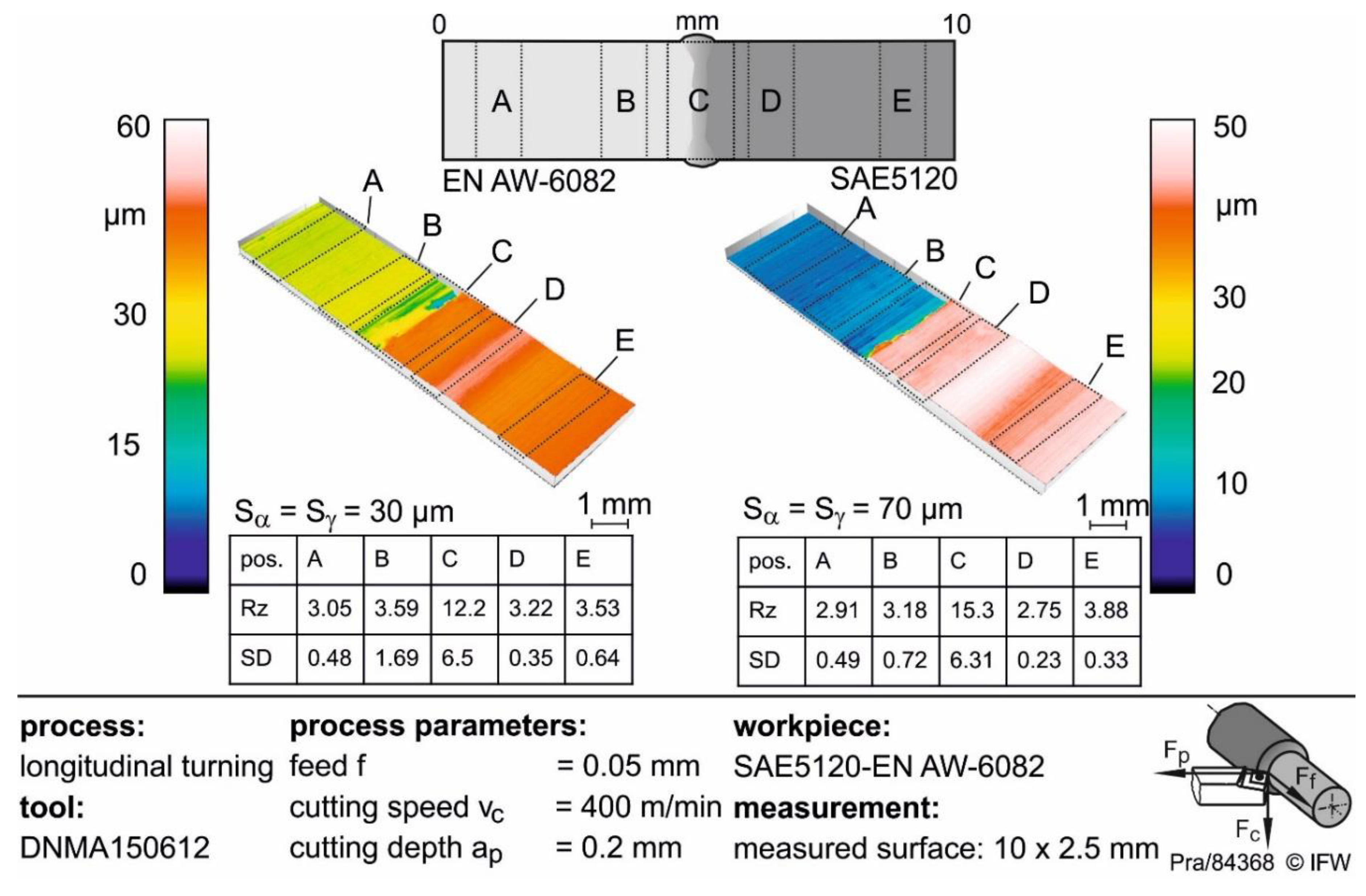
Surface quality and surface roughness of turned steel–aluminium alloy shaft subjected to different cutting edge roundings are shown in Figure 11. The measurements were carried out both in the base material area (pos. A, B, D and E) and in the joining zone area (pos. C). Surface height difference in the material transition zone increases by using a larger cutting edge rounding which is observed by the topography pictures. Surface roughness Rz decreases in average with increasing cutting edge rounding as the contact length with the component surface grows. This in turn leads to a reduction of roughness peak heights. In the HAZ in both surfaces an increase of surface roughness is noticeable compared to the base material. The reason for this is on the one hand different machining behaviour by cutting materials with different properties in the transition zone as well as changes in the chip formation and the appearance and variation of built-up edges by passing different materials or the welding seam. Despite that, a shape deviation in the area of the joining zone is noticeable. The elevation in the transition zone is according to the tool displacement due to the hardness differences in the welded area. These results also correlate with the previous results of process forces and seem reasonable.

4. Summary and Outlook

In the current state of the art, requirements like reduction of the component weight or increasing the resistance to certain stresses for solid components are steadily increasing. Hybrid construction methods can meet these requirements. At present, however, there is no knowledge of how different materials can be joined together optimally for complex geometries like a gear shaft and then be processed mechanically in order to set favourable surface and subsurface properties for the service behaviour. Therefore, in this study the influence of the IMP formation for the dissimilar material combination steel–aluminium alloy and the influence of the material combination on the machinability are analysed. The effect of cutting edge micro geometry on the surface and subsurface properties is examined. Relationships between cutting forces, residual stresses and surface roughness are investigated.
The results show that dissimilar shafts can be laser welded, because of the formation of IMP, cracks and pores, and there is a demand to further improve the weld quality. In cross sections and hardness measurements the microstructure of the weld metal, the HAZ and the base materials were evaluated. The measurements show the hardness increase in the weld metal due to the formation of IMP. Depending on the position of the measurement point (weld metal, HAZ) and the microstructure in the weld metal, especially the formation of IMP, the hardness differs. These hardness differences in the corresponding fields are reflected in the machining process. An approach to achieve conditions that are more homogeneous in the weld metal is to stimulate the weld pool during welding. In the framework of the Collaborative Research Centre 1153, a stimulation of the weld pool with ultrasonic vibration is investigated. First results showed a more homogeneous mixing of the elements in the weld metal [22]. The influence of stimulation on machining these specimens still has to be proven. A more homogeneous distribution of the IMP should lead to a more homogeneous hardness distribution and, therefore, to a reduced stress gradient in the transition zone. Due to different material properties of steel-aluminium alloy the machining behavior varies. Above all, the forming of built-up edges is much more distinctive in the aluminium alloy zone than in the steel zone. Therefore, differences according to process forces, surface and subsurface properties could be noticed. A significant influence of different cutting edge roundings on the machining behavior and consequently the machining result of the welded shaft can be seen. With increasing cutting edge rounding, the mechanical load, especially the passive force, increases significantly in the HAZ of steel. This leads to higher compressive residual stresses in the joining zone. In the aluminium alloy HAZ the process forces lightly decrease. A cause for this could be the changed material properties in the HAZ or the presence of IMP in the weld metal, which also leads to a different cutting behaviour. The difference between residual stresses decreases in the joining zone as well as in the base materials for smaller cutting edge rounding. The effect of different residual stress states on the application behavior has to be investigated in further proceedings. Furthermore, surface roughness decreases with rising cutting edge rounding. The reason for that is the reduction of roughness peak heights through the larger contact length with the component surface. Comparing the surface roughness in the different base material areas, there are hardly any differences visible. The cause for that is the appearance of built-up edges depending on the tendency of a material to strain hardening. This leads to a different machining behavior as a result of different material properties. With the help of the acquired knowledge about the machining behavior of laser-welded components, a process parameter control in the material transition zone can take place. This enormously increases the potential of both the production within the tolerances and load-adapted hybrid components.

Author Contributions

S.N., J.H. and S.K. designed the laser beam welding process, manufactured the welded workpieces and carried out the analysis of hardness and microstructure; H.O. and J.T. designed a large part of the laser beam welding fixture device; J.H. is the supervisor of S.N.; S.K., J.W. and T.H. are the supervisors of the A3 subproject; L.O. is the doctoral supervisor of S.N.; B.D., B.B., T.G. and V.P. designed the cutting process, performed the cutting experiments and carried out the analysis of surface and subsurface properties; B.D., B.B. and T.G. are the supervisors of V.P. and B.D. and B.B. are the supervisors of the B4 subproject.

Funding

This research was funded by the German Research Foundation (DFG, Deutsche Forschungsgemeinschaft) within the framework of the Collaborative Research Centre (Sonderforschungsbereich SFB 1153, Projektnummer: 252662854, Teilprojekt A4, B4), which is promoted by the DFG.

Acknowledgments

The results presented in this paper were obtained within the Collaborative Research Centre 1153 “Process chain to produce hybrid high-performance components by Tailored Forming” in subprojects A3 and B4. The authors would like to thank the German Research Foundation (DFG) for the financial support of this project.

Conflicts of Interest

The authors declare no conflict of interest.

References

  1. Hultgren, R.; Desai, P.D.; Hawkins, D.T.; Gleiser, M.; Kelley, K.K. Selected Values of the Thermodynamic Properties of Binary Alloys; ASM International: Materials Park, OH, USA, 1973; pp. 156–165. [Google Scholar]
  2. Kattner, U.R.; Burton, B.P. Al-Fe (Aluminum-Iron). In ASM Handbook Vol. 3: Alloy Phase Diagrams; Baker, H., Ed.; ASM International: Materials Park, OH, USA, 1992. [Google Scholar]
  3. Rjabow, W.R.; Losowskaja, A.W. Untersuchung der Schmelzzone zwischen Aluminium und Stahl. Schweißtechnik 1968, 18, 399–403. [Google Scholar]
  4. Nothdurft, S.; Springer, A.; Kaierle, S.; Ross, J.; Stonis, M. Laser Soldering and Brazing of Steel-aluminum Sheets for Tailored Hybrid Tubes. J. Laser Appl. 2016, 28, 022429. [Google Scholar] [CrossRef]
  5. Meco, S.; Pardal, G.; Ganguly, S.; Williams, S.; McPherson, N. Application of laser in seam welding of dissimilar steel to aluminium joints for thick structural components. Opt. Lasers Eng. 2015, 67, 22–30. [Google Scholar] [CrossRef] [Green Version]
  6. Schimek, M.; Springer, A.; Pfeifer, R.; Kaierle, S. Laser welding of dissimilar materials for lightweight construction and special applications. In Proceedings of the SPIE 8603, High-Power Laser Materials Processing: Lasers, Beam Delivery, Diagnostics, and Applications II; SPIE: New York, NY, USA, 2013; Volume 86030J. [Google Scholar] [CrossRef]
  7. Kaierle, S.; Pfeifer, R.; Seffer, O.; Schimek, M.; Bös, J.; Bolchoun, A. Laserstrahlschweißen von Stahl an Aluminium mittels spektroskopischer Kontrolle der Einschweißtiefe und erhöhter Anbindungsbreite durch zweidimensional ausgeprägte Schweißnähte; FAT-Schriftenreihe 263, Final Report, AiF-FKZ 378 ZN/1; Forschungsvereinigung Automobiltechnik: Berlin, Germany, 2014. [Google Scholar]
  8. Lahdo, R.; Seffer, O.; Kaierle, S.; Overmeyer, L. In-process control of penetration depth for high-power laser welding of thick dissimilar joints of steel and aluminum. In Proceedings of the International Congress on Applications of Lasers & Electro-Optics (ICALEO), Orlando, FL, USA, 14–18 October 2018. [Google Scholar]
  9. Huanga, L.; Huaa, X.; Wua, D.; Lia, F. Numerical study of keyhole instability and porosity formation mechanism inlaser welding of aluminum alloy and steel. J. Mater. Process. Technol. 2018, 252, 421–431. [Google Scholar] [CrossRef]
  10. Suder, W.; Ganguly, S.; Williams, S.; Paradowska, A.; Colegrove, P. Comparison of joining efficiency and residual stresses in laser and laser hybrid welding. Sci. Technol. Weld. Join. 2011, 16, 244–248. [Google Scholar] [CrossRef] [Green Version]
  11. Breidenstein, B. Oberflächen und Randzonen hoch Belasteter Bauteile. Post Doctoral Lecturer Qualification, Leibniz Universität Hannover, Hannover, Germany, 2011. [Google Scholar]
  12. Matsumoto, Y.; Hashimoto, F.; Lahoti, G. Surface integrity generated by precision hard turning. CIRP Ann. Manuf. Technol. 1999, 48, 59–62. [Google Scholar] [CrossRef]
  13. Data sheet Cr-Mn-legierter Einsatzstahl 1.7147/1.7149 20MnCr5/20MnCrS5. Available online: https://www.dew-stahl.com/fileadmin/files/dew-stahl.com/documents/Publikationen/Werkstoffdatenblaetter/Baustahl/1.7147_1.7149_de.pdf (accessed on 15 November 2018).
  14. Data Sheet 3.2315—AlMgSi1/AlSiMgMn. Available online: https://www.schmolz-bickenbach.de/fileadmin/files/schmolz-bickenbach.de/documents/Datenblaetter/6082.pdf (accessed on 15 November 2018).
  15. Denkena, B.; Reichstein, M.; Brodehl, J.; de León Garcia, L. Surface Preparation, coating and wear performance of geometrically defined cutting edges. In Proceedings of the 5th International Conference the Coatings in Manufacturing Engineering. Key Eng. Mater. 2005, 438, 1–7. [Google Scholar] [CrossRef]
  16. Bragg, W.H.; Bragg, W.L. The reflection of X-Rays by crystals. Proc. R. Soc. A Math. Phys. 1913, 88, 428–438. [Google Scholar] [CrossRef]
  17. Breidenstein, B.; Denkena, B.; Prasanthan, V. Energy dispersive residual stress determination. In Proceedings of the 2nd Internationale Konferenz Euro Hybrid Materials and Structures, Kasierslautern, Germany, 20–21 April 2016; pp. 211–215. [Google Scholar]
  18. Breidenstein, B.; Denkena, B.; Prasanthan, V. Non-destructive determination of residual stress depth profiles of hybrid components by energy dispersive residual stress measurement. Key Eng. Mater. 2017, 742, 613–620. [Google Scholar] [CrossRef]
  19. Mazar Atabaki, M.; Nikodinovski, M.; Chenier, P.; Ma, J.; Harooni, M.; Kovacevic, R. Welding of Aluminum Alloys to Steels: An Overview. J. Manuf. Sci. Prod. 2014, 14, 59–78. [Google Scholar]
  20. Klaus, M. Röntgendiffraktometrische Ermittlung tiefenabhängiger Eigenspannungsverteilungen in Dünnschichtsystemen mit Komplexen Aufbau. Ph.D. Thesis, Technische Universität Berlin, Berlin, Germany, 2009. [Google Scholar]
  21. Deutsches Institut für Normung. Metallic Materials—Vickers Hardness Test—Part 1: Test Method (ISO 6507-1:2018); German Version EN ISO 6507-1:2018; Beuth Verlag: Berlin, Germany, 2018. [Google Scholar]
  22. Nothdurft, S.; Seffer, O.; Lahdo, R.; Hermsdorf, J.; Kaierle, S. Laser beam joining of dissimilar joints of steel and aluminium alloys. Weld. Cut. 2018, 17, 392–398. [Google Scholar]
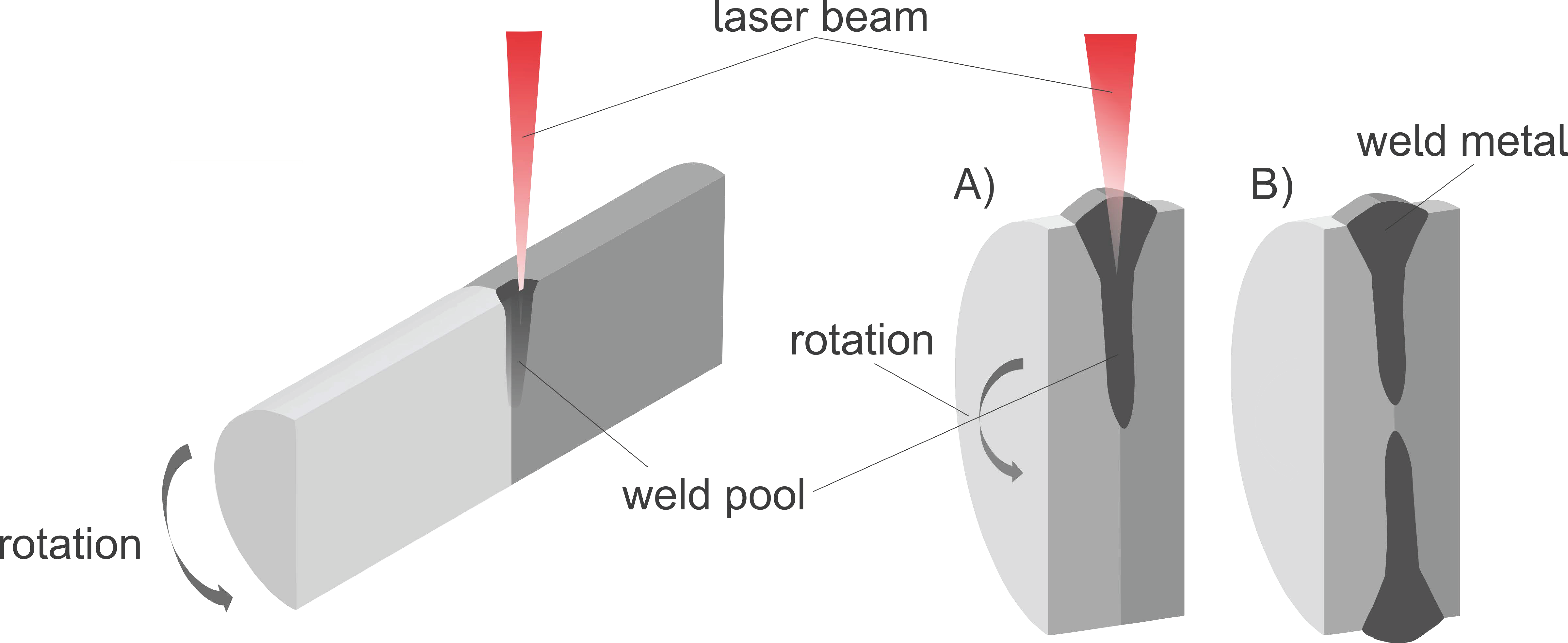
Figure 1. Left: Schematic drawing of the welding process, right: schematic drawings of the sample geometries in cross section while (A) and after (B) welding.
Metals 09 00134 g001
Figure 2. Characterization of the cutting edge microgeometry.
Metals 09 00134 g002
Figure 3. Zoomed part from Figure 1b and a corresponding micrograph of a metallographic cross section of a steel-aluminium alloy weld.
Metals 09 00134 g003
Figure 4. Energy-dispersive residual stress determination method.
Metals 09 00134 g004
Figure 5. Metallographic cross section of a dissimilar steel-aluminium alloy weld (cracks and pores exemplarily marked).
Metals 09 00134 g005
Figure 6. Metallographic cross section of the measured surface of the steel–aluminium alloy welds with visible hardness indentations (dashed line: course of the measurements).
Metals 09 00134 g006
Figure 7. Hardness measurement for two different laser beam welded samples of SAE5120 and EN AW-6082.
Metals 09 00134 g007
Figure 8. Influence of cutting edge geometry on cutting forces during turning of a steel–aluminium alloy welded shaft.
Metals 09 00134 g008
Figure 9. Built-up edges during orthogonal cutting of steel-aluminium alloy.
Metals 09 00134 g009
Figure 10. Influence of cutting edge geometry on transversal residual stress parallel to the surface in different depths of turned steel-aluminium alloy welded shaft.
Metals 09 00134 g010
Figure 11. Influence of cutting edge geometry on surface roughness of turned steel-aluminium alloy welded shaft.
Metals 09 00134 g011
Table 1. Chemical compositions.
wt%FeAlCSiMnCrSZnTiCu
SAE5120 (1.7147) 1bal.-0.17–0.22≤0,41.10–1.401.00–1.20≤0.035---
EN AW-6082 (3.2315) 20.50bal.-0.70–1.300.4–1.00.25-0.200.100.10
1: [13]; 2: [14]; bal. = balance.
Table 2. Material properties.
MaterialHardness 1Tensile Strength 2,3Yield Strength 2,3
Unit(HV0.1)(MPa)(MPa)
SAE5120 (1.7147)≅ 180≥980≥685
EN AW-6082 (3.2315)≅ 96310≥260
1 measured; 2: [13]; 3: [14].
Table 3. Process parameters of the cutting operation.
ParameterUnitAluminium Alloy–SteelSteel–Aluminium Alloy
Cutting Speed(m/min)400 and 180400 and 180
Feed(mm)0.050.05
Cutting Depth(mm)0.20.2
Cutting Edge Geometry Sα/Sγ(-)30/30 and 70/7030/30 and 70/70