Article

Creep Behavior of Inconel 718 Produced by Laser Powder Bed Fusion (LPBF)

by
Daniel Augusto de Souza Borges
1,
Gisele Fabiane Costa Almeida
1,
Suzana Noronha Ferreira Ribeiro
1,
Gleicy de Lima Xavier Ribeiro
2,
Paulo Henrique Tedardi do Nascimento
3,
Rodolfo Luiz Prazeres Gonçalves
1,
Carlos Roberto Camello Lima
1,
Marcos Massi
1 and
Antônio Augusto Couto
1,*
1
School of Engineering, Mackenzie Presbyterian University, São Paulo 01302-907, SP, Brazil
2
Senai Institute of Innovation in Advanced Manufacturing, São Bernardo do Campo 09861-790, SP, Brazil
3
Termomecanica São Paulo S.A., São Bernardo do Campo 09612-000, SP, Brazil
*
Author to whom correspondence should be addressed.
Metals 2026, 16(6), 641; https://doi.org/10.3390/met16060641
Submission received: 13 May 2026 / Revised: 30 May 2026 / Accepted: 3 June 2026 / Published: 10 June 2026
(This article belongs to the Special Issue Recent Advances in Powder-Based Additive Manufacturing of Metals)

Abstract

Additive manufacturing using laser powder bed fusion (LPBF) has been widely used to produce nickel-based superalloy components with complex shapes for high-temperature applications requiring creep resistance. In this research, the creep behavior of LPBF Inconel 718 under solution and double-aging heat treatments, performed at 590–650 °C under stresses of 450–550 MPa, is studied. The characterization included optical microscopy, scanning electron microscopy (SEM), porosity analysis, Vickers microhardness tests, and fracture surface examination. The findings revealed that even after heat treatment, the material maintained a mainly directional, columnar microstructure, with an average porosity below 1%, which was unevenly distributed and contained critical defects related to lack-of-fusion (LOF) and trapped powder. Fracture after creep presents regions of ductile failure alongside facets indicative of quasi-cleavage. Kinetic analysis revealed a high stress exponent (n = 18.26) and an activation energy (Qc = 410–538 kJ/mol), indicating that the deformation operates within the power-law breakdown (PLB) regime, where dislocation–precipitate interactions govern the creep rate in this precipitation-strengthened superalloy. Overall, the results highlight that the directional microstructure and residual defects typical of LPBF can reduce the creep resistance of Inconel 718, underscoring the importance of post-processing methods and internal defect control specifically tailored for additively manufactured materials.

1. Introduction

Inconel 718 (IN718) is a nickel superalloy developed in the 1960s for demanding aerospace and industrial applications. It is a Ni–Cr–Fe alloy with additions of Nb, Mo, Ti, and Al, combining corrosion and oxidation resistance with good thermomechanical performance [1]. Due to these characteristics, IN718 is used in gas turbines, turbocharger rotors, and components subject to critical thermomechanical stresses, where creep behavior acts as the primary life-limiting factor for these high-temperature components [2].
The microstructure of IN718 is based on an austenitic (γ) matrix, with precipitation hardening of γ′ (Ni3(Al,Ti)) and γ″ (Ni3Nb) phases. The γ″ phase is crucial for high-temperature strength by providing an effective barrier to dislocation motion [3,4]. Prolonged exposure or aging can promote phases such as δ (Ni3Nb), which are incoherent with the matrix, alter the Nb distribution, and modify mechanical behavior, especially at grain boundaries [4]. Nb segregation during processing favors the formation of the Laves phase, which reduces ductility and promotes cracking, impacting fatigue and creep [5]. Studies also address the formation and dissolution of the Laves phase in IN718 by laser processing, revealing limitations in homogenization and dissolution kinetics during heat treatments [6].
With additive manufacturing, interest in the production of IN718 by LPBF is increasing, where the metal powder is selectively melted from a 3D model, building the part layer by layer [1,7]. LPBF offers geometric freedom and material efficiency, but the final properties depend on the processing parameters and the powder, which can cause porosity and discontinuities that impair mechanical performance [8]. Studies discuss volumetric energy density (VED) as a process energy metric, highlighting that different combinations of parameters can generate defects even with similar VED, making it important to analyze the operating range along with porosity and mesostructure [9,10]. LPBF-IN718 exhibits a microstructure with columnar grains preferentially aligned along the build direction and strong crystallographic textures, leading to anisotropic properties even after heat treatment [7,11]. Recent research confirms that this preferred orientation is governed by the interaction between the scanning strategy and the local heat flow, allowing the creation of tailored microstructures [12].
In the context of creep, studies indicate that performance is lower when loading is perpendicular to the construction direction, due to the orientation and effective area of grain boundaries under normal stress, as well as the nucleation and growth of cavities in preferential trajectories [13,14,15]. There are also residual stresses from rapid thermal cycles, relevant to mechanical performance [1].
The recent literature has advanced the understanding of creep behavior in LPBF-IN718. However, numerous studies remain focused on specific test conditions and particular point approaches, such as variations in build orientation or post-processing routes. This focus impedes the ability to compare findings and to consolidate the relationships between microstructure, kinetics, and fracture at various service intervals [13,14,16]. It is essential to expand analyses that incorporate kinetic parameters (such as stress exponent and apparent activation energy), microstructural evidence, and fractography. Such analyses should consider solution and aging treatments, as well as the influence of precipitates and phases on high-temperature creep failure [17,18,19,20,21].
This study investigates the creep behavior of LPBF-IN718 at 590, 620, and 650 °C under stresses of 450 to 550 MPa and correlates the results with microstructural and fractographic analyses. The kinetic parameters ( ε ˙ s , n e Q c ) are discussed alongside microstructural and fracture evidence to elucidate deformation and damage mechanisms relevant to high-temperature applications. The analysis is conducted within the scope of the investigated creep conditions and the as-heat-treated condition, without HIP processing or detailed γ′/γ″ quantification, whose potential effects on the creep response are also considered.

2. Materials and Methods

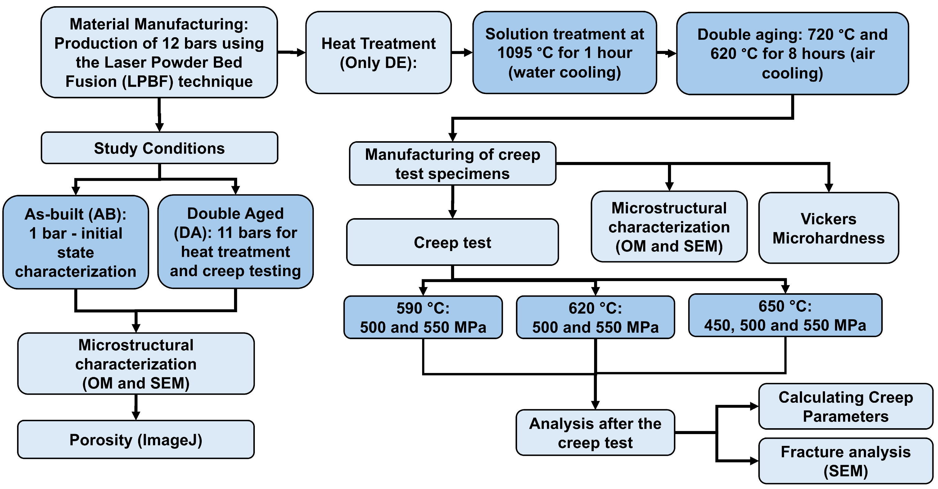
All stages of the experimental development of this work were systematically organized and are presented in Figure 1, which illustrates, through a flowchart, the sequence of activities carried out from the initial preparation to the final analysis of the results. This visual resource provides a clear and objective understanding of the methodological sequence adopted.
The IN718 superalloy used in this study was produced by LPBF (OmniSint-160, Omnitek, São Paulo, Brazil). Processing was performed with a laser power of 167 W, a scanning speed of 700 mm/s, a hatching distance of 0.07 mm, a layer thickness of 0.03 mm, and a 45° rotation between layers (alternating strategy). As a comparative metric, volumetric energy (VED) can be estimated according to Equation (1):
V E D = P v h t
where P is the laser power, v the scanning speed, h the hatch spacing (distance between adjacent tracks), and t the layer thickness, resulting in approximately 113.6 J/mm3 for the parameters used. The nominal chemical composition of the material is presented in Table 1 and meets the ASTM B637 requirements [22].
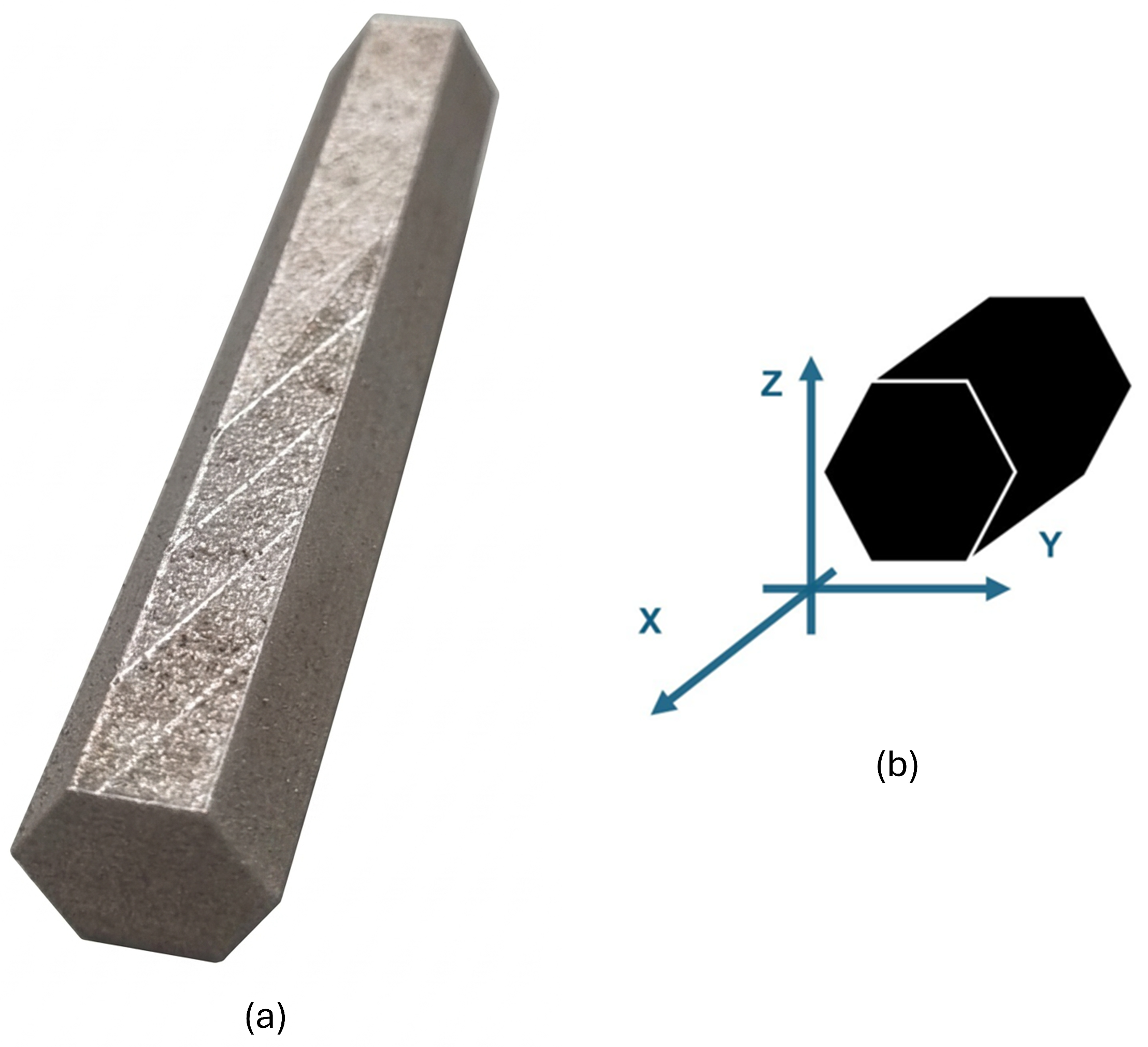
A total of twelve bars with a hexagonal parallelepiped geometry were produced (Figure 2). One bar was preserved in as-built condition (AB) for microstructural analysis. The remaining test bars were subjected to solution treatment at 1095 °C for 1 h, followed by water cooling, and double aging at 720 °C for 8 h (air cooling) and 620 °C for 8 h (air cooling). The specimens subjected to this heat treatment were designated as being in the double-aged (DA) condition. The DA bars were machined into creep test specimens.
Microstructural characterization used optical microscopy (OM) (Olympus BX60, Tokyo, Japan) and scanning electron microscopy (SEM) equipped with energy-dispersive X-ray spectroscopy (EDS) (Jeol JSM-6510, Tokyo, Japan, Thermo Scientific UltraDry, Madison, WI, USA). Samples under AB and DA conditions were ground with SiC papers, polished with diamond paste, and etched with aqua regia (10 mL HNO3 + 30 mL HCl). Analyses were conducted before and after creep tests. The fracture surfaces of the test specimens after the creep tests were analyzed using SEM to identify the fracture mechanisms and morphologies associated with creep damage.
Porosity was quantified exclusively under the AB condition using ImageJ software version 1.52a (National Institutes of Health, Bethesda, MD, USA), based on 10 OM micrographs. In each image, the pore fraction was determined relative to the total analyzed area.
Vickers microhardness (HV0.1, 100 gf) was evaluated using a DuraScan 70 device (ZwickRoell, Ulm, Germany). In the AB condition, measurements were taken on the XY, XZ, and YZ planes to analyze possible variations associated with the manufacturing orientation. In the DA condition, measurements were performed exclusively on the YZ plane. For each condition and plane, 10 measurements were taken.
Creep tests were conducted in accordance with the ASTM E139 standard [23]. The specimens utilized are shown in Figure 3. Although ASTM E139 references the geometric proportions of ASTM E8/E8M [24] for cross-sectional uniformity, the gauge length was selected to optimize high-temperature extensometer coupling and thermal zone stability within the furnace. All specimens were extracted horizontally along the X-axis, meaning the tensile load during the creep tests was applied perpendicular to the LPBF building direction (Z-axis). The creep tests under constant load were performed with the Kappa 10DS (ZwickRoell). Tests were conducted at 590, 620, and 650 °C under stresses of 450, 500, and 550 MPa; at 620 °C, only at 500 and 550 MPa. Deformation was monitored using extensometers connected to a Linear Variable Differential Transformer (LVDT) system. From the strain–time curves, the time to rupture ( t f ), primary creep time ( t p ), failure strain ( ε f ), steady-state creep rate ( ε ˙ s ), were determined to analyze creep behavior and dominant mechanisms. The steady-state creep rate was calculated via linear regression over the minimum-slope zone of the strain–time curves. Based on the correlation of these results under different testing conditions, activation energy ( Q c ) and stress exponent ( n ) were calculated, which are essential parameters for inferring the dominant deformation mechanisms. The fracture surfaces of the test specimens after the creep tests were analyzed using SEM to identify the fracture mechanisms and morphologies associated with creep damage.

3. Results and Discussion

3.1. Optical and Scanning Electron Microscopy

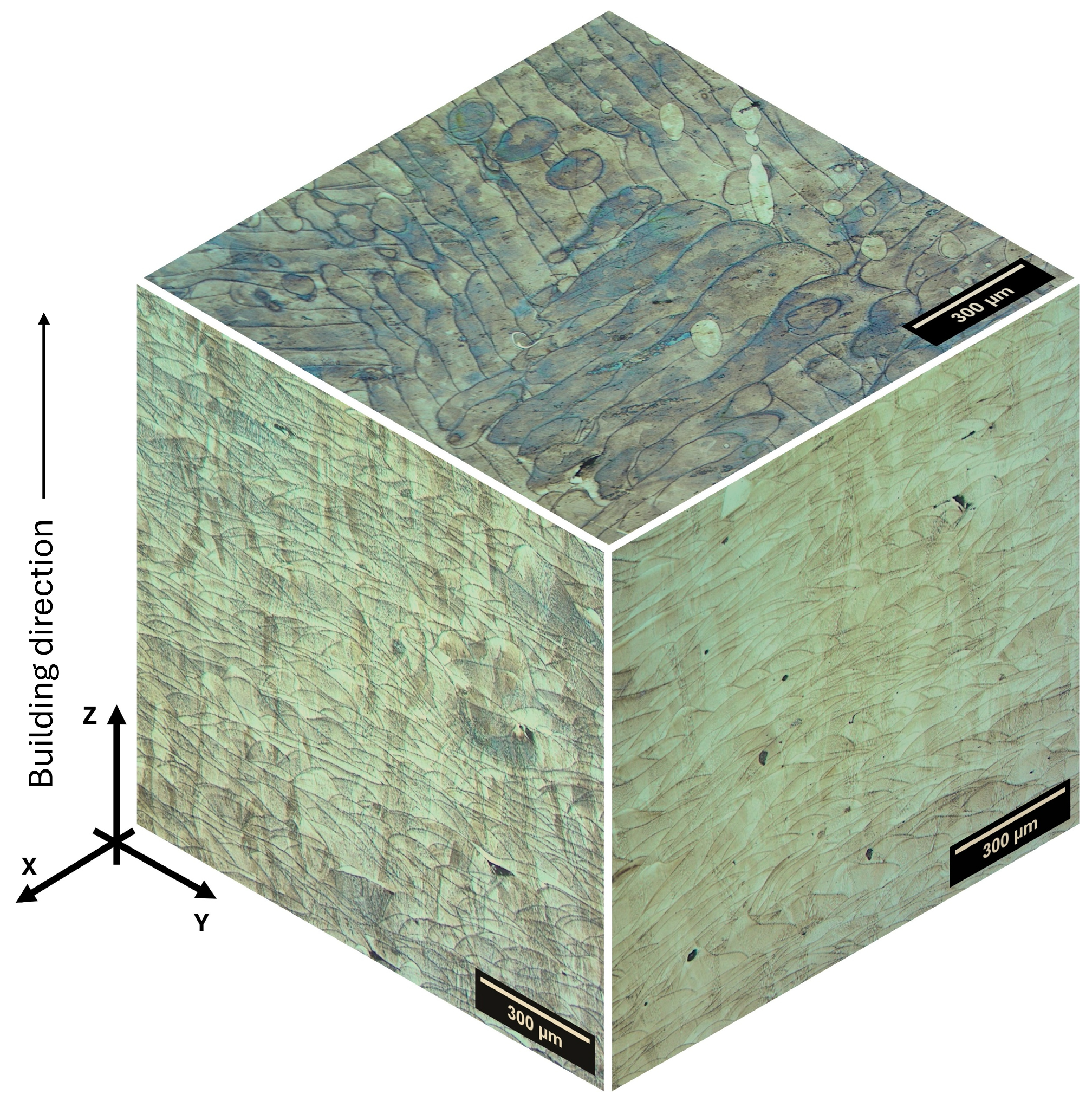
The microstructure of LPBF-IN718 in the AB condition is shown in OM in Figure 4. The assembly of the three orthogonal sections (XY, XZ, and YZ) highlights the typical morphological anisotropy, in which overlapping fish scale melt pools are associated with the scanning strategy and the overlap between successive tracks. From a processing perspective, the geometry and continuity of these pools, including their width, depth, and overlap, can vary depending on the parameter range adopted. Additionally, the literature often employs volumetric energy density (VED) as a comparative metric to discuss fusion regimes and sensitivity to defects or mesostructure [9,10]. Although VED does not capture all relevant factors, such as contour strategies, atmospheric conditions, and spot size, it helps situate the parameter set within the state of the art.
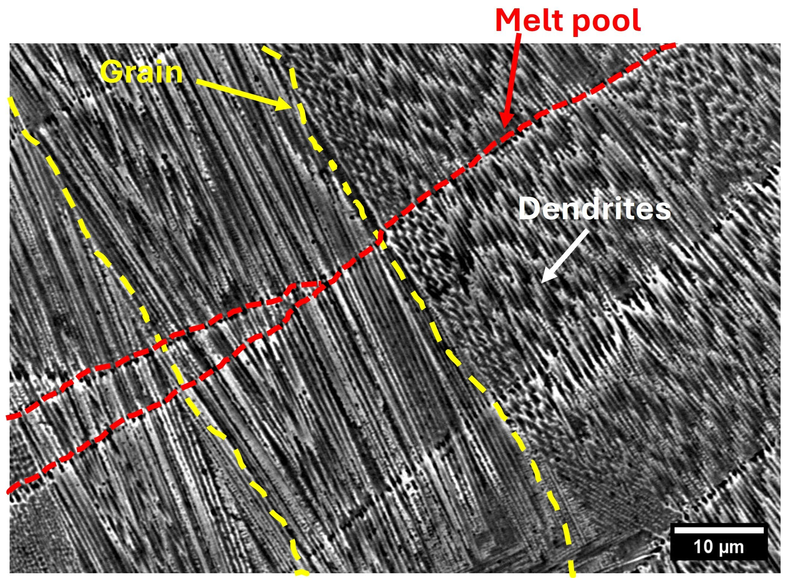
The SEM micrographs of the AB condition (Figure 5) show a thin cellular and dendritic substructure aligned with the build direction (BD), consistent with elevated solidification rates in LPBF and preferential growth along the heat flow. During laser treatment of IN718, rapid solidification can induce microsegregation of Nb in interdendritic regions, promoting the formation of Nb-rich phases, such as Laves phases or carbides, depending on the thermal history. SEM contrasts in these areas reveal a non-uniform distribution of solutes, as shown by microstructural analyses conducted during laser manufacturing. Recent studies detail the formation and dissolution of the Laves phase, which depend on solubilization, homogenization, and diffusion [6].
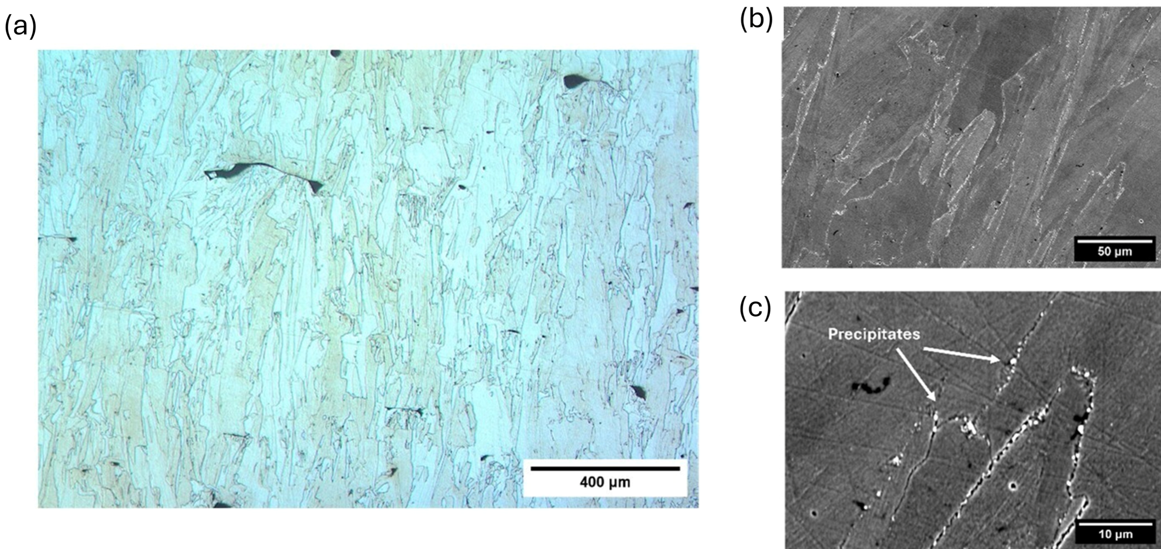
The microstructure in the DA condition was analyzed by OM and SEM, as shown in Figure 6 on the YZ face. In Figure 6a, a greater homogeneity is observed compared to the AB condition, with fewer pool boundaries. In Figure 6b, a columnar grain structure at the micrometer scale is noticeable, indicating that the heat treatment did not promote complete recrystallization, thus preserving the directional inheritance of LPBF. This observation is consistent with the recrystallization kinetics in IN718-LPBF, where the most pronounced recrystallization occurs at temperatures ≥ 1130–1150 °C, depending on the time, while lower temperatures favor recovery and limited subgrain growth [25,26]. Ni et al. [27] also reported that the microstructure of LPBF can evolve into more equiaxed grains through recrystallization at higher temperatures or prolonged times. In this study (1095 °C/1 h), the directional morphology observed in Figure 6b indicates incomplete recovery and recrystallization, whereas the columnar dendritic microstructure in the AB condition is no longer visible in SEM after the treatment, suggesting reduced microsegregation and partial homogenization.
Figure 6c shows precipitates along grain boundaries, which are important for high-temperature performance. In IN718, these precipitates can include the δ phase (Ni3Nb), carbides, and Ti/N/O-rich particles, which may be inherited from the powder or formed by oxidation. The evolution of γ″ and the stability of δ depend on the thermal cycle, as δ consumes Nb and can affect precipitation hardening and boundary response [3,4]. Studies indicate that changes in solution treatment influence precipitates at boundaries and the response of high-temperature properties, such as creep rupture [17]. Thus, boundary precipitates in DE may result from solute redistribution or act as preferred pathways for intergranular damage during creep.

3.2. Porosity

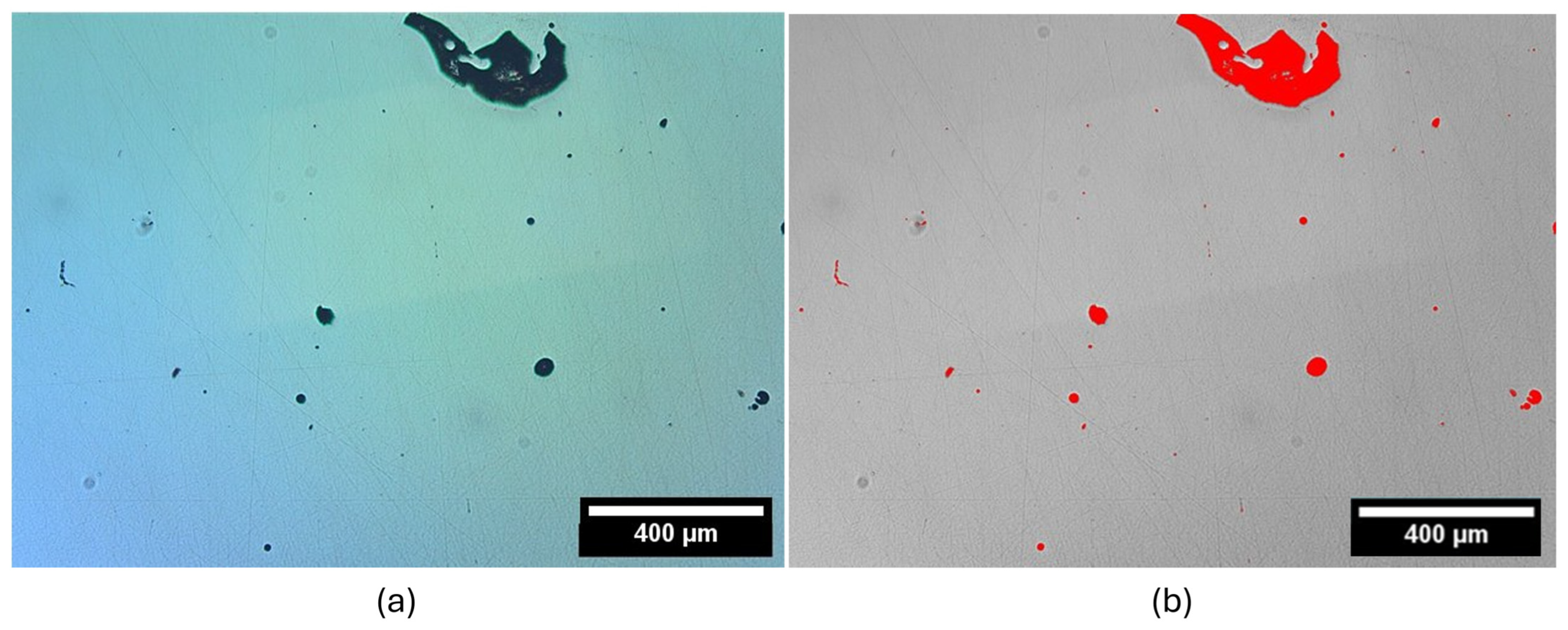
The time until creep rupture is sensitive to nucleation, growth, and coalescence of voids, and porosity is commonly present in materials produced by additive manufacturing. Pre-existing defects can act as stress concentrators and crack initiation points at high temperatures, depending on the size, morphology, and location of the pore [28]. The porosity of LPBF-IN718 was evaluated in the YZ (longitudinal) and XY (transverse) planes using optical image analysis, a common approach for the comparative quantification of defects in additive materials [29], as illustrated in Figure 7. The average porosity values were 0.98% ± 0.78% in the YZ plane and 0.77% ± 0.70% in the XY plane, indicating an average porosity below 1%. However, the high standard deviations suggest a heterogeneous distribution, with regions containing a higher number of pores, a condition typical in laser fusion manufacturing processes (LPBF), due to thermal variations, scanning trajectory, or changes in the fusion regime. In addition to the total fraction, pore size and density also influence creep. Simulations indicate that higher initial porosity reduces the cross-sectional area, increases local stresses, and accelerates initial creep, thereby promoting defect formation. For constant porosity, a higher density of small pores can accelerate crack formation due to more sites, increasing the creep rate and reducing lifespan [28]. Even with an average porosity below 1%, regions with defects and pore agglomeration of tens of micrometers can compromise structural reliability, requiring strict control and monitoring. Works that correlate process history (including VED), microstructure, and high-temperature performance reinforce the idea that defects and microstructural heterogeneities should be considered in an integrated manner to interpret failure mechanisms and pathways in creep/failure stages [18].

3.3. Vickers Microhardness

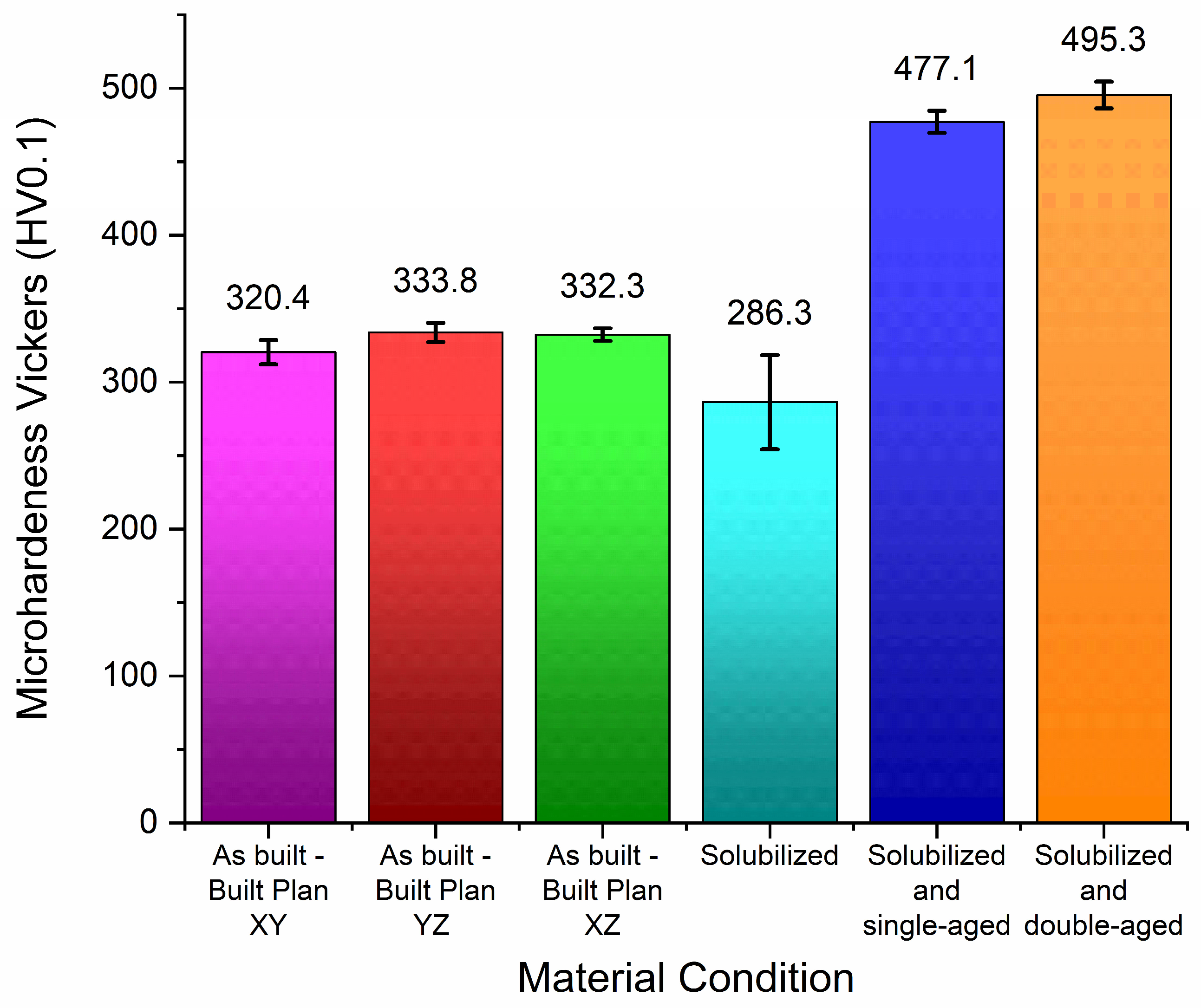
Figure 8 illustrates the variation in Vickers microhardness as a function of processing planes and post-printing heat treatments. In the AB condition, the average values showed a maximum variation of 13.4 HV (approximately 4% of the mean), indicating low hardness anisotropy on the indentation scale, despite the highly directional microstructure inherited from the LPBF process. Similar microstructural responses for the LPBF-produced IN718 have been reported by Wang et al. [30], confirming that microhardness differentials between orthogonal planes can be minimal under comparable processing parameters. However, microhardness remains a localized measurement that may not fully reflect the macroscopic effects of crystallographic texture and grain morphology. These directional characteristics manifest more significantly in anisotropic mechanical properties—such as tensile strength, impact toughness, and creep behavior—where performance is heavily dictated by the loading axis relative to the building orientation, as discussed further for post-treated LPBF IN718 [31].
The sample subjected only to solubilization showed a hardness reduction of about 13% compared to the AB condition, aligning with the recovery and relief of residual stresses in LPBF, as well as the redistribution of heterogeneities in the AB condition. In solubilization treatments of IN718-LPBF, the decrease in hardness generally results from the reduction in the hardening in the AB condition and the microstructural reorganization before aging, where the dissolution of Nb-rich phases can provide Nb for γ″ precipitation [25,32]. It is noted that the dispersion of values after solubilization is greater, indicating residual heterogeneity in the local response. After aging, there was an increase in hardness due to the precipitation of hardening phases γ″ (Ni3Nb) and γ′ (Ni3(Al,Ti)), whose controlled distributions promoted precipitation hardening in IN718 [3,4].
The solubilization condition, combined with the first aging process, resulted in an approximately 67% increase compared to the solubilized condition. The peak hardness was observed after the DA, with a relatively small additional increase (~3.8%) compared to the first aging, suggesting that most of the precipitation hardening occurred during the first stage, while the second stage promotes adjustments and refinement of the precipitated state. This behavior aligns with the literature reporting a greater response in hardness and mechanical strength when the distribution of fine precipitates (especially γ″) is favored by appropriate aging routes [33,34,35].

3.4. Creep Tests

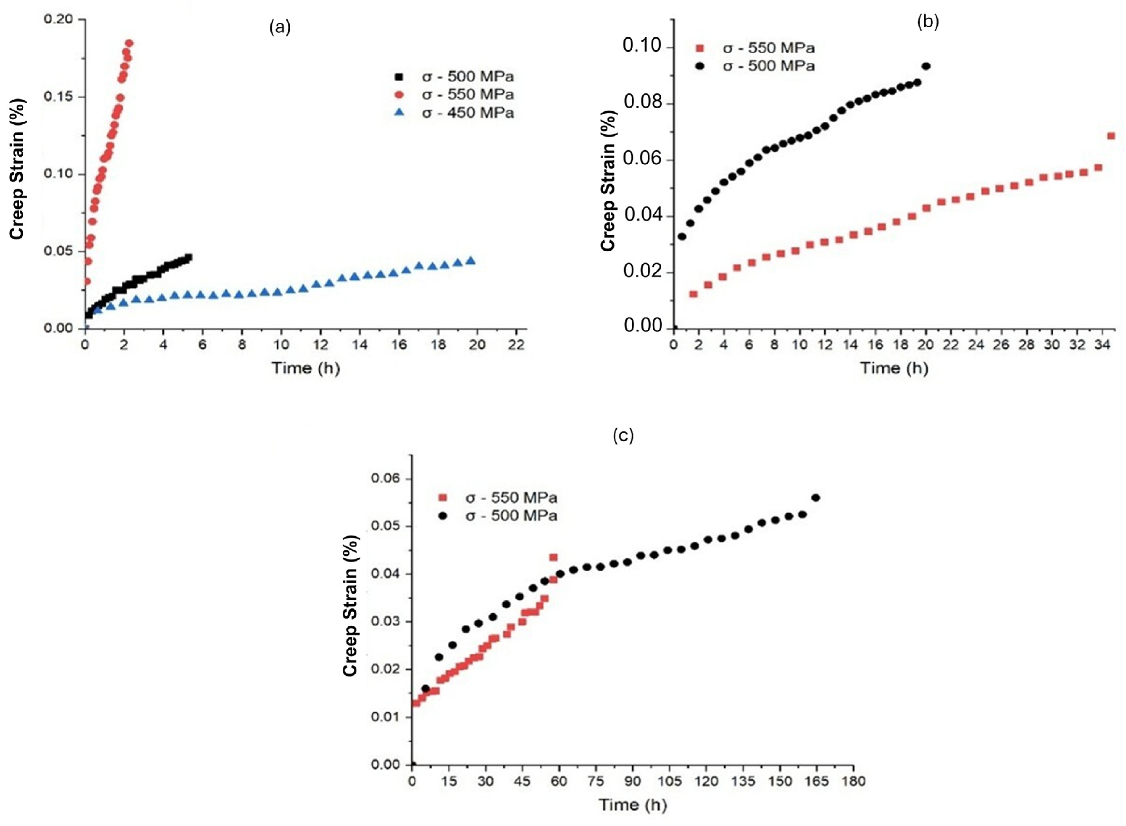
All experimental creep data are presented in Table 2 and Figure 9. Creep curves typically follow the expected trend of decreasing creep life (tf) and increasing steady-state rate ( ε ˙ s ) under higher temperatures and stresses. This reflects accelerated thermal activation kinetics and an increased driving force for dislocation-controlled deformation and damage accumulation [36,37].
At 590 °C, the material showed the longest rupture times and the lowest minimum rates. The value of (tp) was high at 590 °C and 500 MPa (21.96 h), suggesting a prolonged primary stage and slow evolution toward the steady-state creep stage, behavior consistent with conditions of lower temperature [36]. Concurrently, the minimum secondary creep rate reached its lowest value, 1.64 × 10⁻⁴ h−1, which directly accounts for the extended creep rupture life (164.67 h) observed at this temperature, despite the relatively low strain accumulated at the point of fracture (0.0560%).
At 650 °C, increasing the stress caused an increase in ( ε ˙ s ) and a drastic reduction in (tf). The curves indicate a short steady-state creep stage, especially at high stresses, followed by a rapid transition to the tertiary, suggesting rapid damage evolution (nucleation/coalescence of voids and microcracks, and geometric instability) [36]. At 550 MPa, the ( ε ˙ s ) is high and ( ε f ) is elevated, suggesting a test with accelerated deformation, amplifying microstructural differences and the influence of critical defects.
Even after solution treatment and double aging, the creep results are lower than those reported for IN718 forged under similar conditions, and some studies with IN718-LPBF with process optimization or HIP. The comparison with Oros et al. [19] is illustrative: for heat-treated IN718-AM subjected to HIP, at 650 °C and a stress of 488 MPa, a tf of 935.3 h with an ( ε f ) of 0.30% was reported. In the current study, under a stress of 500 MPa, a tf of 5.27 h, and an ( ε f ) of 4.63%, a large performance deviation was observed. This discrepancy is consistent with the literature, which highlights HIP as a decisive tool for closing internal pores and reducing critical defects, substantially increasing creep life in LPBF superalloys [17,18,19,38]. Creep performance of LPBF-IN718 strongly depends on orientation/anisotropy, defect density, precipitates, hardening state, and sweep strategy. Sanchez et al. [13] demonstrated that adjustments to strategy and orientation can even lead to comparable or superior performance to forging under certain conditions, while Sabari et al. [21] and Kaletsch et al. [15] reinforce that creep anisotropy in LPBF-IN718 is multifactorial (grain morphology, texture, microsegregation, and precipitate distribution). In this study, the combination of initial porosity and the inheritance of a directional microstructure typical of LPBF constitutes a strong hypothesis for the reduction in tf and alteration of ( ε f ) [16,28].
At 620 °C (Figure 9b), an atypical behavior was observed; at 550 MPa, the tf was higher than at 500 MPa, accompanied by a lower secondary creep rate ( ε ˙ s ). This result conflicts with the decreased creep life expectancy at higher stress and should be discussed as a possibly multifactorial effect. First, this anomaly could be attributed to inherent material scatter, which is common in laser powder bed fusion (LPBF) components; since the stresses are extremely high and the rupture times are short, localized defects or sample variations could easily induce premature failure in the 500 MPa specimen. Alternatively, a physically consistent hypothesis is in situ precipitation during the test, since 620 °C coincides with one of the characteristic aging temperatures of IN718. Theska et al. [4] describe that, in this range, preferential precipitation of γ″ can occur in dislocations, and under high stresses, the transport of Nb by pipe diffusion along dislocations can accelerate local precipitation processes, producing a transient reinforcement that reduces secondary creep rate ( ε ˙ s ) and delays rupture.
Higher stress, of 550 MPa, may have led to a microstructure that naturally hardened during creep, showing a longer primary stage and a slower rate at 500 MPa; it might not have reached similar kinetics or nucleation conditions. Since this is an LPBF material, variability between specimens is especially associated with the heterogeneous distribution of pores and critical defects. These reverse trends observed in series without replicates are deeply connected to localized variations in crack nucleation and the transition to the tertiary creep stage [16,28]. Heterogeneities associated with the thermal history of the build (as variations along the construction height) have been reported to alter the creep properties and increase the dispersion of results under the same test conditions [39]. Thus, the most coherent interpretation is to present this result as atypical behavior with two plausible explanations (dynamic precipitation hardening versus statistical effect of defects) and to recommend that future work test replicates under these conditions.
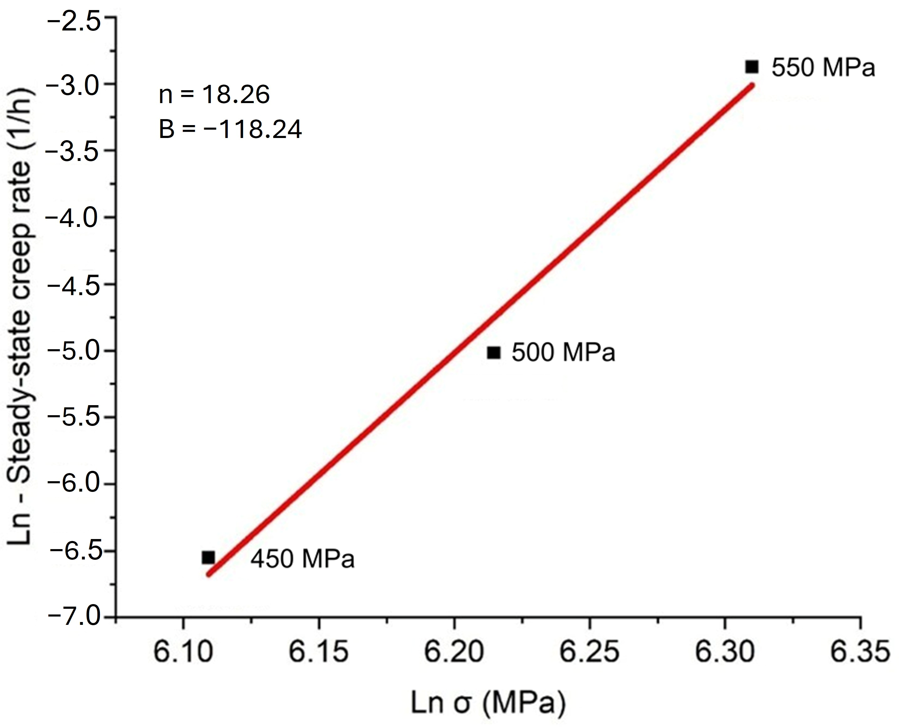
Figure 10 illustrates the logarithmic correlation between steady-state creep rates and applied stress at 650 °C. Employing conventional regression techniques, the stress exponent (n), which describes how the steady-state creep rate on stress was ascertained in accordance with the power law [36]. The resulting fit yields an apparent stress exponent of approximately 18.3. According to the classic frameworks established by Evans and Wilshire [36], such an elevated value severely exceeds the conventional power-law regime (n > 3) typically associated with standard diffusion-controlled dislocation climb. Instead, this substantial exponent indicates that the creep kinetics operate well within the power-law breakdown (PLB) domain under these high-stress conditions [16,19]. In precipitation-hardened superalloys like LPBF Inconel 718, these high apparent n values are fundamentally governed by threshold stress effects and strenuous dislocation–precipitate interactions, where the high applied stress drives the shearing of coherent γ″ and γ′ particles [16,40]. This behavior aligns with Caliari et al. [40], who reported apparent stress exponents between 8.7 and 18.7 for IN718 in the double-aged (DA) condition, as well as recent findings by Oros et al. [19] and Bryndza et al. [16] regarding localized deformation and dynamic phase stability under severe stress levels.
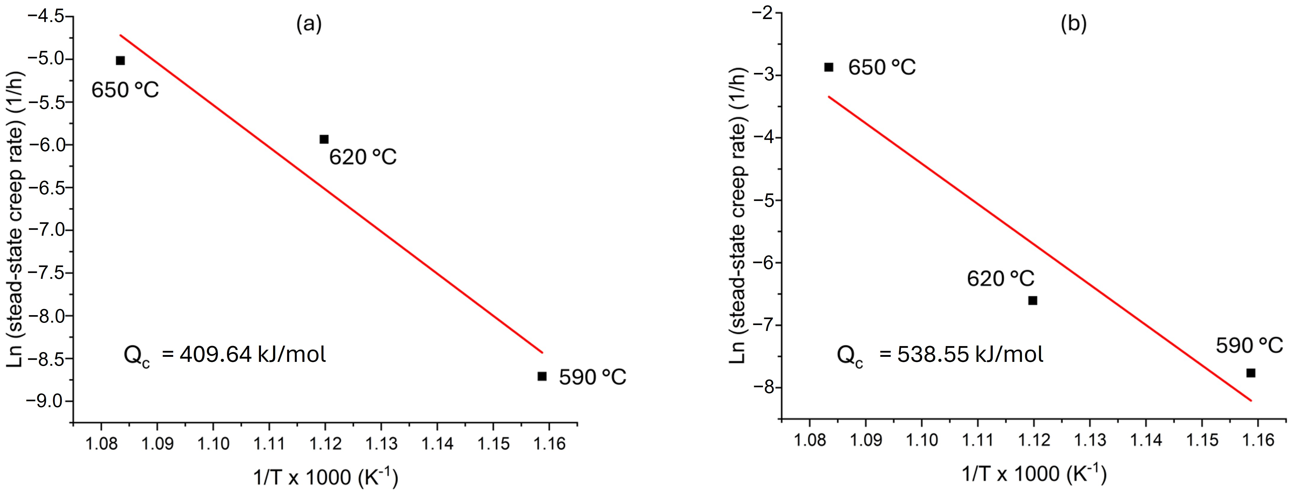
The apparent activation energy (Qc) was evaluated using the Arrhenius-type relationship between the steady-state creep rate and temperature at 500 MPa and 550 MPa (Table 2), as shown in Figure 11, which is high and reflects not only diffusion in the γ matrix but also microstructure and precipitate (γ″/γ′) effects on dislocation control and degradation kinetics. The order of magnitude is consistent with dislocation mechanisms, especially dislocation climb, reported for IN718 at high temperatures, particularly when reinforced by γ″ [2,36,40].
In summary, the results indicate that IN718-LPBF (even after DA) exhibits creep performance strongly conditioned by inherent microstructural anisotropy, where the directional grain boundary architecture and texture alter the effective area and boundary orientation under normal stress, influencing cavity nucleation and damage propagation [13,14,15,21]. This relationship between high-temperature damage evolution and the directional microstructure inherited from LPBF (texture, boundaries, and post-treatment state) is also reported by He et al. [41], reinforcing the role of crystallographic orientation and boundary architecture in creep life. Inherent defects in the LPBF (porosity/LOF) can act as stress concentrators and accelerate the transition to tertiary damage and premature rupture [16,28] and the state of precipitates (γ″/γ′ and possible boundary phases), which controls resistance to dislocation movement (and therefore ( ε ˙ s )) and can also influence degradation modes at grain boundaries at high temperatures [2,17,18]. Despite n and Qc values, an accelerated deformation regime operating within the power-law breakdown (PLB) domain, the shortened creep lifetimes at 650 °C and high early strains indicate the importance of defect-accelerated degradation and directional microstructural features. These findings agree with the literature comparing LPBF-processed and forged Inconel 718 [19,20,42].

3.5. Fracture Analysis

Fractographic analysis using SEM was performed to identify fracture mechanisms after creep tests, correlating them with thermomechanical conditions and LPBF material characteristics (porosity, LOF defects, microstructural heterogeneities). For greater representativeness and comparability, three conditions were selected: the most severe (650 °C/550 MPa), the least severe (590 °C/500 MPa), and one with atypical creep life behavior (620 °C/550 MPa). In all cases, the surfaces reveal that failure is influenced by process defects and rapid degradation at high temperatures, with mixed fracture modes, consisting of microvoid coalescence and quasi-cleavage facets, which are typical of accelerated deformation regimes within the power-law breakdown (PLB) domain that lead to significantly shortened creep lifetimes [16,38].
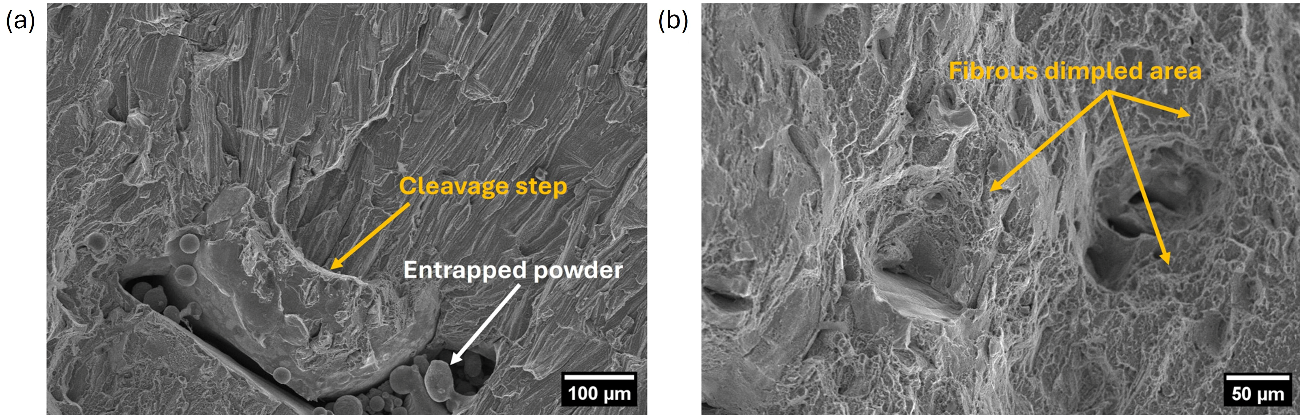
At 650 °C and 550 MPa, the fracture shows evidence of accelerated damage, consistent with a high steady-state creep rate and shortened creep lifetime, in which the tertiary state tends to dominate rapidly. At low magnification (Figure 12a), a volumetric defect with irregular morphology is observed, associated with multiple spherical particles, a feature consistent with an LOF defect and entrapped powder (white arrows). This type of discontinuity acts as a stress concentrator and can control damage nucleation and the transition to fracture in LPBF materials, particularly under severe conditions [8,10,28,43]. It is possible to observe some cleavage steps (orange arrows) and cleavage facets. However, a mixed-mode mechanism is evidenced when comparing different scales and areas. At higher magnifications (Figure 12b), the analysis reveals fibrous dimpled areas associated with microvoid coalescence. The simultaneous presence of cleavage and ductile regions is consistent with creep fracture under severe conditions, where critical defects can initiate cracks, and localized deformation in the tertiary stage can produce void coalescence before complete failure [19,38].
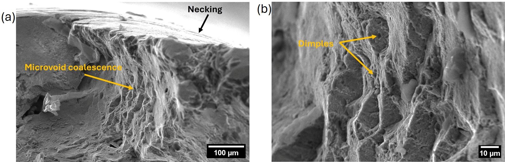
At 590 °C and 500 MPa (Figure 13), the fracture surface shows ductile morphology, with signs of microvoid coalescence. At low magnifications (Figure 13a), there is a fracture with plastic deformation, microvoid coalescence (orange arrow), and curvature at the edge, such as necking (black arrow). At higher magnifications (Figure 13b), the surface is dominated by dimples, typical of transgranular ductile microvoid fracture. This indicates damage that evolves slowly, with the prolonged primary creep stage (tp = 21.96 h) and the exceptionally low minimum creep rate 1.64 × 10⁻⁴ h−1, obtained under this condition before transitioning to tertiary acceleration [2,36]. In this region, dimples in elongated sections suggest a shear component in the final fracture. The pattern contrasts with more severe conditions (620 °C and 650 °C at 550 MPa), reinforcing the idea that, by reducing temperature and stress, there is a tendency towards more ductile failure, with fewer cleavages. In IN718-LPBF, studies show that less severe conditions lead to more ductile fracture, while severe conditions or those with more defects favor mixed responses and are sensitive to stress concentrators [38,44].
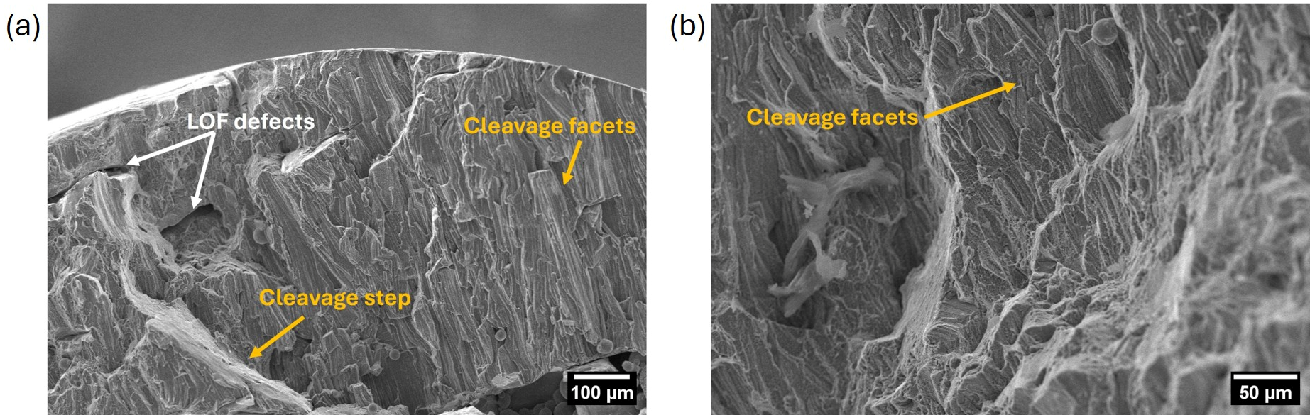
At 620 °C and 550 MPa (Figure 14), fractography shows, at low magnification (Figure 14a), a region with spherical particles associated with discontinuity, consistent with an LOF defect (white arrows). The presence of this defect can dominate crack nucleation and growth, contributing to dispersed results, especially in LPBF materials with heterogeneous defect distribution [16,28]. Different melting modes and parameters can generate distinct defect populations, including those with similar VED, underscoring the importance of pore type rather than just average porosity [9,10,43]. Facets and cleavage steps are also observed (orange arrows). At higher magnification (Figure 14b), the fracture surface is mainly faceted, showing flat facets (orange arrows) and linear markings, indicating a mixed fracture with a quasi-cleavage component. There is no clear evidence of intergranular fracture, but the faceted morphology and the presence of critical defects indicate stress-concentrated controlled failure and accelerated transition to the tertiary stage at high stress. This is also related to the directional features of the inherited microstructure and differences in service life in IN718-LPPF, where the inherent microstructural anisotropy and defect sensitivity influence the localized stress state and the resulting fracture mode [41].
A comparison of the conditions reveals a pattern: in the less severe condition (590 °C/500 MPa), there is ductile fracture due to microvoids coalescence, indicating gradual damage and fracture with high plasticity; in the severe conditions or those with more defects (620 °C and 650 °C at 550 MPa), mixed fracture occurs, with facets and quasi-cleavage, due to defects such as LOF and pores that increase stress concentration and accelerate damage and transition to tertiary creep.
These results corroborate the literature, which attributes performance differences between IN718-LPBF and forged to the combination of anisotropic microstructure and critical defects (columnar grains, texture) and show that strategies such as parameter optimization and HIP can extend service life at high temperatures by reducing porosity and defects [18,19,38]. Furthermore, the state of precipitates (γ″/γ′) and boundary phases, although not identified in fractography, can affect resistance to dislocation motion and susceptibility to grain boundary damage at elevated temperatures, as discussed in IN718-LPBF stress-rupture studies and post-treatments [2,17,18].

4. Conclusions

This work investigated the creep behavior of LPBF-IN718 subjected to solution treatment followed by double aging. Creep tests (590, 620, and 650 °C; 450–550 MPa) were complemented by microstructural characterization, porosity assessment, and fractographic analysis. The main conclusions are as follows:
The LPBF material exhibited a columnar microstructure aligned with the construction direction, which persisted after heat treatment and testing, indicating an absence of complete recrystallization that would eliminate the directional inheritance.
The average porosity was <1% (0.98% ± 0.78% in YZ; 0.77% ± 0.70% in XY), but high standard deviations indicated a heterogeneous distribution of defects. Fractography showed that porosity/LOF/entrapped powder acted as stress concentrators and damage nucleation sites, compromising creep life.
At 620 °C, atypical creep behavior was observed (tf at 550 MPa > 500 MPa), possibly associated with microstructural effects during the test (temperature range close to the aging of IN718) or statistical variability linked to critical defects; systematic replicates are recommended under these conditions.
The n ≈ 18.3 and Qc ≈ 410–538 kJ/mol values indicate high stress sensitivity operating within the power-law breakdown (PLB) regime, rather than conventional dislocation climb. These parameters remain apparent due to strong threshold stress effects induced by intense dislocation–precipitate interactions (particle shearing), combined with the inherent microstructural scatter typical of LPBF-processed material.
Fracture surfaces exhibited mixed features, transitioning from transgranular microvoid coalescence characterized by ductile dimples under less severe conditions toward quasi-cleavage and cleavage facets under more severe conditions. In all cases, the systematic predominance of transgranular damage and the absence of intergranular cavitation confirm the activation of the power-law breakdown (PLB) regime driven by precipitate shearing, where inherent LPBF defects (such as lack-of-fusion) acted as primary sites for accelerated crack nucleation and failure propagation.
Taken together, the results indicate that conventional thermal cycles of IN718 (developed for forged material) may not be sufficient to mitigate directional inheritance and defect sensitivity in LPBF; strategies such as parameter optimization and HIP tend to be beneficial for reducing critical porosity and improving creep reliability.

Author Contributions

Conceptualization, D.A.d.S.B. and A.A.C.; methodology, D.A.d.S.B.; validation, G.F.C.A., S.N.F.R., G.d.L.X.R., R.L.P.G., P.H.T.d.N., C.R.C.L., M.M. and A.A.C.; formal analysis, D.A.d.S.B.; investigation, D.A.d.S.B., G.F.C.A., S.N.F.R., G.d.L.X.R., R.L.P.G., P.H.T.d.N., C.R.C.L., M.M. and A.A.C.; resources, M.M.; data curation, D.A.d.S.B.; writing—original draft preparation, D.A.d.S.B.; writing—review and editing, all authors; visualization, D.A.d.S.B.; supervision, A.A.C.; project administration, A.A.C.; funding acquisition, M.M. and A.A.C. All authors have read and agreed to the published version of the manuscript.

Funding

This research was funded by the National Council for Scientific and Technological Development (CNPq), grant numbers 407050/2023-0 and 306559/2024-2, and by MackPesquisa, project number 251031.

Data Availability Statement

The original contributions presented in this study are included in the article. Further inquiries can be directed to the corresponding author.

Acknowledgments

The authors would like to thank the National Council for Scientific and Technological Development (CNPq) and MackPesquisa for their support.

Conflicts of Interest

Author Paulo Henrique Tedardi do Nascimento was employed by the company Termomecanica São Paulo S.A . The remaining authors declare that the research was conducted in the absence of any commercial or financial relationships that could be construed as a potential conflict of interest.

References

  1. Hosseini, E.; Popovich, V.A. A Review of Mechanical Properties of Additively Manufactured Inconel 718. Addit. Manuf. 2019, 30, 100877. [Google Scholar] [CrossRef] [Scilit]
  2. Sugahara, T.; Couto, A.A.; Barboza, M.J.R.; Neto, F.P.; Takahashi, R.J.; Reis, D.A.P. Creep and Mechanical Behavior Study of Inconel 718 Superalloy. Mater. Res. 2022, 25, e20210280. [Google Scholar] [CrossRef] [Scilit]
  3. Kuo, Y.L.; Nagahari, T.; Kakehi, K. The Effect of Post-Processes on the Microstructure and Creep Properties of Alloy718 Built up by Selective Laser Melting. Materials 2018, 11, 996. [Google Scholar] [CrossRef] [Scilit]
  4. Theska, F.; Nomoto, K.; Godor, F.; Oberwinkler, B.; Stanojevic, A.; Ringer, S.P.; Primig, S. On the Early Stages of Precipitation during Direct Ageing of Alloy 718. Acta Mater. 2020, 188, 492–503. [Google Scholar] [CrossRef] [Scilit]
  5. Ardi, D.T.; Guowei, L.; Maharjan, N.; Mutiargo, B.; Leng, S.H.; Srinivasan, R. Effects of Post-Processing Route on Fatigue Performance of Laser Powder Bed Fusion Inconel 718. Addit. Manuf. 2020, 36, 101442. [Google Scholar] [CrossRef] [Scilit]
  6. Zhang, S.; Wang, L.; Lin, X.; Yang, H.; Huang, W. The Formation and Dissolution Mechanisms of Laves Phase in Inconel 718 Fabricated by Selective Laser Melting Compared to Directed Energy Deposition and Cast. Compos. B Eng. 2022, 239, 109994. [Google Scholar] [CrossRef] [Scilit]
  7. Huynh, T.; Mehta, A.; Graydon, K.; Woo, J.; Park, S.; Hyer, H.; Zhou, L.; Imholte, D.D.; Woolstenhulme, N.E.; Wachs, D.M.; et al. Microstructural Development in Inconel 718 Nickel-Based Superalloy Additively Manufactured by Laser Powder Bed Fusion. Metallogr. Microstruct. Anal. 2022, 11, 88–107. [Google Scholar] [CrossRef] [Scilit]
  8. Kumar, P.; Farah, J.; Akram, J.; Teng, C.; Ginn, J.; Misra, M. Influence of Laser Processing Parameters on Porosity in Inconel 718 during Additive Manufacturing. Int. J. Adv. Manuf. Technol. 2019, 103, 1497–1507. [Google Scholar] [CrossRef] [Scilit]
  9. de Leon Nope, G.V.; Perez-Andrade, L.I.; Corona-Castuera, J.; Espinosa-Arbelaez, D.G.; Muñoz-Saldaña, J.; Alvarado-Orozco, J.M. Study of Volumetric Energy Density Limitations on the IN718 Mesostructure and Microstructure in Laser Powder Bed Fusion Process. J. Manuf. Process. 2021, 64, 1261–1272. [Google Scholar] [CrossRef] [Scilit]
  10. Liu, H.; Cheng, W.; Sun, Y.; Ma, R.; Wang, Y.; Bai, J.; Xue, L.; Song, X.; Tan, C. Effects of Process Parameters and Heat Treatment on Microstructure and Mechanical Characteristics of Laser Powder Bed Fusion Alloy Inconel 718. Coatings 2023, 13, 189. [Google Scholar] [CrossRef] [Scilit]
  11. Wu, S.; Peng, H.Z.; Gao, X.; Hodgson, P.D.; Song, H.Y.; Zhu, Y.M.; Tian, Y.; Huang, A.J. Improving Creep Property of Additively Manufactured Inconel 718 through Specifically-Designed Post Heat Treatments. Mater. Sci. Eng. A 2022, 857, 144047. [Google Scholar] [CrossRef] [Scilit]
  12. Gokcekaya, O.; Ishimoto, T.; Hibino, S.; Yasutomi, J.; Narushima, T.; Nakano, T. Unique Crystallographic Texture Formation in Inconel 718 by Laser Powder Bed Fusion and Its Effect on Mechanical Anisotropy. Acta Mater. 2021, 212, 116876. [Google Scholar] [CrossRef] [Scilit]
  13. Sanchez, S.; Gaspard, G.; Hyde, C.J.; Ashcroft, I.A.; Ravi, G.A.; Clare, A.T. The Creep Behaviour of Nickel Alloy 718 Manufactured by Laser Powder Bed Fusion. Mater. Des. 2021, 204, 109647. [Google Scholar] [CrossRef] [Scilit]
  14. Shi, J.J.; Zhou, S.A.; Chen, H.H.; Cao, G.H.; Russell, A.M.; Zhou, Z.J.; Qi, X.B.; Li, C.P.; Chen, G.F. Microstructure and Creep Anisotropy of Inconel 718 Alloy Processed by Selective Laser Melting. Mater. Sci. Eng. A 2021, 805, 140583. [Google Scholar] [CrossRef] [Scilit]
  15. Kaletsch, A.; Qin, S.; Broeckmann, C. Influence of Different Build Orientations and Heat Treatments on the Creep Properties of Inconel 718 Produced by PBF-LB. Materials 2023, 16, 4087. [Google Scholar] [CrossRef] [Scilit]
  16. Bryndza, G.; Tchuindjang, J.T.; Chen, F.; Habraken, A.M.; Sepúlveda, H.; Tuninetti, V.; Mertens, A.; Duchêne, L. Review of the Microstructural Impact on Creep Mechanisms and Performance for Laser Powder Bed Fusion Inconel 718. Materials 2025, 18, 276. [Google Scholar] [CrossRef] [Scilit]
  17. Chizari, A.M.; Kermanpur, A.; Foroozmehr, E.; Rezaeian, A.; Sadeghi, F.; Rezaei, A. Effect of Solution Treatment on Microstructure and Stress Rupture Properties of Precipitation Hardened IN718 Superalloy Fabricated by Laser Powder-Bed Fusion Process. J. Mater. Res. Technol. 2022, 21, 2296–2308. [Google Scholar] [CrossRef] [Scilit]
  18. Du, J.; Cheng, W.; Sun, Y.; Ma, R.; Liu, H.; Song, X.; Yang, J.; Tan, C. The Effect of Precipitates on the Stress Rupture Properties of Laser Powder Bed Fusion Inconel 718 Alloy. Coatings 2023, 13, 2087. [Google Scholar] [CrossRef] [Scilit]
  19. Oros, T.J.; Son, K.; Hodge, A.M.; Kassner, M.E. The High Temperature Creep and Fracture Behavior of Inconel 718 Produced by Additive Manufacturing. Scr. Mater. 2024, 251, 116208. [Google Scholar] [CrossRef] [Scilit]
  20. Zhang, S.; Weng, K.; Guo, C.; Zhao, H.; Lin, X.; Wang, L.; Yang, H.; Huang, W. The Creep Behavior of IN718 Alloy Fabricated by Selective Laser Melting Compared to Forging. Appl. Mater. Today 2024, 38, 102252. [Google Scholar] [CrossRef] [Scilit]
  21. Sabari, S.R.; Koundinya, N.T.B.N.; Murty, S.V.S.N.; Nagesha, B.K.; Janaki Ram, G.D.; Kottada, R.S. Understanding the Role of Microstructure on Creep Anisotropy in Additively Manufactured IN718. Mater. Charact. 2025, 223, 114935. [Google Scholar] [CrossRef] [Scilit]
  22. ASTM B637; Standard Specification for Precipitation-Hardening Nickel Alloy Bars, Forgings, and Forging Stock for High-Temperature Service. American Society for Testing and Materials (ASTM): West Conshohocken, PA, USA, 1998.
  23. ASTM E139-11; Standard Test Methods for Conducting Creep, Creep Rupture, and Stress Rupture Tests of Metallic Materials. American Society for Testing and Materials (ASTM): West Conshohocken, PA, USA, 2011.
  24. ASTM E8/E8M-11; Standard Test Methods for Tension Testing of Metallic Materials. American Society for Testing and Materials (ASTM): West Conshohocken, PA, USA, 2011.
  25. Huang, W.; Yang, J.; Yang, H.; Jing, G.; Wang, Z.; Zeng, X. Heat Treatment of Inconel 718 Produced by Selective Laser Melting: Microstructure and Mechanical Properties. Mater. Sci. Eng. A 2019, 750, 98–107. [Google Scholar] [CrossRef] [Scilit]
  26. Doğu, M.N.; Davut, K.; Obeidi, M.A.; Yalçın, M.A.; Gu, H.; Low, T.S.E.; Ginn, J.; Brabazon, D. Recrystallization and Grain Growth Kinetics of IN718 Manufactured by Laser Powder Bed Fusion. J. Mater. Res. Technol. 2022, 19, 4242–4257. [Google Scholar] [CrossRef] [Scilit]
  27. Ni, M.; Liu, S.; Chen, C.; Li, R.; Zhang, X.; Zhou, K. Effect of Heat Treatment on the Microstructural Evolution of a Precipitation-Hardened Superalloy Produced by Selective Laser Melting. Mater. Sci. Eng. A 2019, 748, 275–285. [Google Scholar] [CrossRef] [Scilit]
  28. Wu, S.; Song, H.Y.; Peng, H.Z.; Hodgson, P.D.; Wang, H.; Wu, X.H.; Zhu, Y.M.; Lam, M.C.; Huang, A.J. A Microstructure-Based Creep Model for Additively Manufactured Nickel-Based Superalloys. Acta Mater. 2022, 224, 117528. [Google Scholar] [CrossRef] [Scilit]
  29. Tiberto, D.; Klotz, U.E.; Held, F.; Wolf, G. Additive Manufacturing of Copper Alloys: Influence of Process Parameters and Alloying Elements. Mater. Sci. Technol. 2019, 35, 969–977. [Google Scholar] [CrossRef] [Scilit]
  30. Wang, Z.; Guan, K.; Gao, M.; Li, X.; Chen, X.; Zeng, X. The Microstructure and Mechanical Properties of Deposited-IN718 by Selective Laser Melting. J. Alloys Compd. 2012, 513, 518–523. [Google Scholar] [CrossRef] [Scilit]
  31. Neikter, M.; Raja, D.C.; Balachandramurthi, A.R.; Harlin, P. Tailored Ductility and Strength for Enhanced Impact Toughness of Laser Powder Fusion Built Alloy 718. J. Alloys Compd. 2021, 884, 161374. [Google Scholar] [CrossRef] [Scilit]
  32. Gruber, K.; Dziedzic, R.; Kuźnicka, B.; Madejski, B.; Malicki, M. Impact of High Temperature Stress Relieving on Final Properties of Inconel 718 Processed by Laser Powder Bed Fusion. Mater. Sci. Eng. A 2021, 813, 141111. [Google Scholar] [CrossRef] [Scilit]
  33. Tucho, W.M.; Hansen, V. Studies of Post-Fabrication Heat Treatment of L-PBF-Inconel 718: Effects of Hold Time on Microstructure, Annealing Twins, and Hardness. Metals 2021, 11, 266. [Google Scholar] [CrossRef] [Scilit]
  34. Gruber, K.; Stopyra, W.; Kobiela, K.; Madejski, B.; Malicki, M.; Kurzynowski, T. Mechanical Properties of Inconel 718 Additively Manufactured by Laser Powder Bed Fusion after Industrial High-Temperature Heat Treatment. J. Manuf. Process. 2022, 73, 642–659. [Google Scholar] [CrossRef] [Scilit]
  35. Benzing, J.T.; Derimow, N.; Kafka, O.L.; Hrabe, N.; Schumacher, P.; Godfrey, D.; Beamer, C.; Pathare, P.; Carroll, J.D.; Lu, P.; et al. Enhanced Strength of Additively Manufactured Inconel 718 by Means of a Simplified Heat Treatment Strategy. J. Mater. Process. Technol. 2023, 322, 118197. [Google Scholar] [CrossRef] [Scilit]
  36. Evans, R.W.; Wilshire, B. Introduction to Creep; The Institute of Materials: London, UK, 1993. [Google Scholar]
  37. Lin, Y.; Wang, C.; Sun, Y.; Sun, M.; Yuan, Y.; Gao, Z.; Xiao, Y. Review Article Review on Creep Phenomenon and Its Model in Aircraft Engines. Int. J. Aerosp. Eng. 2023, 2023, 4465565. [Google Scholar] [CrossRef]
  38. Kassner, M.E.; Son, K.T.; Lee, K.A.; Kang, T.H.; Ermagan, R. The Creep and Fracture Behavior of Additively Manufactured Inconel 625 and 718. Mater. High Temp. 2022, 39, 499–506. [Google Scholar] [CrossRef] [Scilit]
  39. Wang, Q.; Ge, S.; Wu, D.; Ma, H.; Kang, J.; Liu, M.; Wang, T.; Narayanaswamy, B.; Su, R. Evolution of Microstructural Characteristics during Creep Behavior of Inconel 718 Alloy. Mater. Sci. Eng. A 2022, 857, 143859. [Google Scholar] [CrossRef] [Scilit]
  40. Caliari, F.R.; Candioto, K.C.G.; Couto, A.A.; Nunes, C.Â.; Reis, D.A.P. Effect of Double Aging Heat Treatment on the Short-Term Creep Behavior of the Inconel 718. J. Mater. Eng. Perform. 2016, 25, 2307–2317. [Google Scholar] [CrossRef] [Scilit]
  41. He, S.; Guo, S.; Xu, Y. Anisotropic Stress Rupture Properties-Microstructure Relationships in SLM Inconel 718 Alloy. Metall. Mater. Trans. A Phys. Metall. Mater. Sci. 2023, 54, 1776–1791. [Google Scholar] [CrossRef] [Scilit]
  42. Xu, Z.; Cao, L.; Zhu, Q.; Guo, C.; Li, X.; Hu, X.; Yu, Z. Creep Property of Inconel 718 Superalloy Produced by Selective Laser Melting Compared to Forging. Mater. Sci. Eng. A 2020, 794, 139947. [Google Scholar] [CrossRef] [Scilit]
  43. Pramod, S.; Kesavan, D. Melting Modes of Laser Powder Bed Fusion (L-PBF) Processed IN718 Alloy: Prediction and Experimental Analysis. Adv. Ind. Manuf. Eng. 2023, 6, 100106. [Google Scholar] [CrossRef] [Scilit]
  44. Xu, J.; Wu, Z.; Niu, J.; Song, Y.; Liang, C.; Yang, K.; Chen, Y.; Liu, Y. Effect of Laser Energy Density on the Microstructure and Microhardness of Inconel 718 Alloy Fabricated by Selective Laser Melting. Crystals 2022, 12, 1243. [Google Scholar] [CrossRef] [Scilit]
Figure 1. Flowchart of the stages of the experimental development of the study, including planning, execution, and data analysis.
Metals 16 00641 g001
Figure 2. LPBF-produced IN718: (a) photograph and (b) schematic representation of the X, Y, and Z axes for micrographic analyses and structural characterizations.
Metals 16 00641 g002
Figure 3. Standard test specimen for creep tests. The reference axes indicate a horizontal extraction orientation along the X-axis, perpendicular to the LPBF building direction (Z-axis).
Metals 16 00641 g003
Figure 4. 3D representation of sections of the LPBF-produced IN718 as-built—morphological differences in the pools in each of the planes.
Metals 16 00641 g004
Figure 5. Scanning electron microscopy of LPBF-IN718 as-built showing columnar grains, dendritic microstructure aligned with the build direction (BD) and melt pool.
Metals 16 00641 g005
Figure 6. DA IN718 alloy (YZ plane): (a) OM showing columnar grains; (b) SEM of columnar structure and grain boundary (GB) precipitates; (c) high-magnification detail of GB precipitates.
Metals 16 00641 g006
Figure 7. LPBF IN718 alloy: (a) original optical micrograph (OM); (b) binarized image for porosity quantification.
Metals 16 00641 g007
Figure 8. Evolution of Vickers microhardness as a function of build orientation and post-printing heat treatments: only solubilized, solubilized and single-aged (720 °C/8 h) and solubilized and double-aged (720 °C/8 h + 620 °C/8 h) and building orientation. Error bars represent the standard deviation.
Metals 16 00641 g008
Figure 9. Creep curves for the DA LPBF IN718 alloy at various stress levels: (a) 650 °C, (b) 620 °C, and (c) 590 °C.
Metals 16 00641 g009
Figure 10. Dependence of steady-state creep rate on applied stress for LPBF IN718 at 650 °C.
Metals 16 00641 g010
Figure 11. Determination of creep activation energy for LPBF IN718 through Arrhenius plots at (a) 500 MPa; (b) 550 MPa.
Metals 16 00641 g011
Figure 12. SEM fractographs of LPBF IN718 after creep testing at 650 °C and 550 MPa: (a) cleavage steps and entrapped powder particles; (b) areas exhibiting fibrous dimples.
Metals 16 00641 g012
Figure 13. SEM fractographs of LPBF IN718 after creep testing at 590 °C and 500 MPa: (a) evidence of microvoid coalescence; (b) areas exhibiting dimples.
Metals 16 00641 g013
Figure 14. SEM fractographs of LPBF IN718 after creep testing at 620 °C and 550 MPa: (a) lack-of-fusion (LOF) defects, cleavage facets, and cleavage steps; (b) detail of cleavage facets.
Metals 16 00641 g014
Table 1. Nominal chemical composition of Inconel 718 alloy (in %).
NiFeCrNb + TaMoTiCoAlMnSiCuCNO
50.00–55.00Balance17.00–21.004.75–5.502.80–3.300.65–1.151 Max.0.20–0.800.35 Max.0.35 Max.0.30 Max.0.08 Max.0.03 Max.0.03 Max.
Table 2. Results of the creep test for LPBF-processed IN718.
Temperature (°C)σ (MPa) t p (h) ε · s (1/h) t f (h) ε f (%)
59050021.961.64 × 10−4164.670.0560
5501.944.24 × 10−457.840.0435
6205000.672.64 × 10−320.020.0934
5502.731.35 × 10−334.710.0675
6504500.651.43 × 10−319.650.0437
5000.356.63 × 10−35.270.0463
5500.225.66 × 10−22.250.1848
Disclaimer/Publisher’s Note: The statements, opinions and data contained in all publications are solely those of the individual author(s) and contributor(s) and not of MDPI and/or the editor(s). MDPI and/or the editor(s) disclaim responsibility for any injury to people or property resulting from any ideas, methods, instructions or products referred to in the content.