Abstract
The orthotropic steel deck is widely used in long-span steel bridges due to its simplicity and efficiency. The welded joint of the U-rib to e deck panel area is extremely sensitive to fatigue cracks. In this study, an orthotropic steel deck with an arc-shape stiffener was proposed that aimed to alleviate the fatigue cracks and enhance the fatigue resistance in long-span steel bridges. Based on the Mingzhu Bay steel bridge, the proposed steel deck FE model was first established. Then, the moving vehicle load was applied to investigate the impact of the arc-shape stiffener on the fatigue stress amplitude and distribution. The Miner fatigue cumulative damage theory was employed to evaluate the fatigue life of the orthotropic steel deck with arc-shaped stiffener, and comparative analyses were carried out. Finally, the results show the maximum stress of the orthotropic steel deck with an arc-shaped stiffener is reduced by 15%, and the fatigue life is improved by 40% compared with the OSD.
1. Introduction
The orthotropic steel bridge deck (OSD) is widely used in long-span bridges due to its light weight, high strength, and construction efficiency [1,2,3,4,5]. In recent years, bridges such as the Jiangyin Yangtze river bridge, the Qingma bridge, and the Hong Kong–Zhuhai–Macao bridge have all adopted an orthotropic steel bridge deck design [6,7]. This type of deck system comprises concrete pavement, steel deck, welded transverse diaphragms, and longitudinal U ribs. However, as a number of weld joints exist in OSD, it is sensitive to fatigue, especially at the welded joints from the rib to deck and U rib to transverse diaphragm [8,9,10,11]. Large numbers of fatigue cracks were found in the existing bridge [12,13,14]. Fatigue cracks are typical problems for OSD and seriously endanger the durability and safety of steel bridge structures.
During the past decades, many efforts were made to investigate the fatigue performance of the OSD. Bu et al. [15] established a finite element model of an orthotropic steel bridge deck to study the influence of the longitudinal position and shape of the initial crack on the fatigue crack propagation process. Jiang et al. [16] considered the probability distribution of random factors for the location of the initial crack, such as the randomness of wheel load, material properties, and initial crack length. Maljaars et al. [17,18] established a linear elastic fracture mechanics model for typical fatigue cracks. The welded joint of the bridge deck was analyzed. Xiao et al. [19] employed finite element software to study the stress analysis and fatigue assessment of steel orthotropic bridge decks and joints. Yu et al. [20] carried out fatigue tests on the typical weld structure details of a steel bridge panel, and the results showed that cracks are prone to occur at the weld position between the longitudinal ribs and the bridge deck outside the longitudinal ribs. Yuasa et al. [21] used a discrete Markov process to simulate fatigue crack growth by considering the resistance of the crack growth process and the randomness of external load. Heng et al. [22] evaluated the fatigue properties of welded joints of orthotropic steel bridge panels with U-shaped ribs with thick edges and compared the fatigue properties with traditional U-shaped ribs, the use of a U rib with thickened edges enhanced the fatigue strength of rib-to-deck joints.
In these studies, the fatigue performance was analyzed by experimental and theoretical methods. As for structural improvement attempts for fatigue problems in OSD, few studies are reported in the literature review. From the structural point of view, the newly designed arc-shaped stiffener was proposed on the top of the bridge deck, where the U rib weld joint is located, as shown in Figure 1.
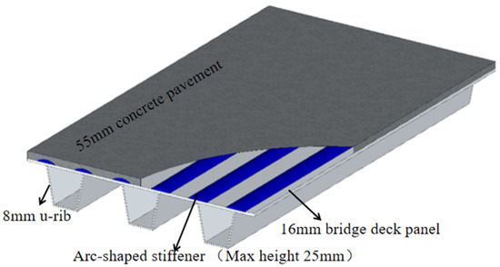
Figure 1.
Schematic diagram of OSD with arc-shaped stiffener.
For engineering applications, the design was based on the actual bridge project of the Mingzhu Bay steel bridge. In this study, the finite element model was established, and the comparative analysis was performed under the moving vehicle load. The sectional stress distribution, crack features, and fatigue life evaluations were studied and presented here.
A novel fatigue resistance steel bridge deck design was proposed in this study. For typical fatigue problems in the existing OSD, the new design can reduce the stress amplitude caused by a moving vehicle load. The thought of this design is to improve the stress distribution evenly and reduce the stress amplitude in order to enhance the fatigue resistance performance. Based on the existing OSD type, the arc-shaped stiffener was advised to mold with the steel deck to avoid the welding. By thickening the steel deck with an arc-shaped stiffener where the U rib welded seam is located below, a more even stress distribution on the steel deck can be obtained. Furthermore, the better cost-effective goal can be achieved by adding a small area of steel arc during the engineering application.
2. Engineering Background
The Mingzhu Bay bridge main bridge is 1016 m and adopts (96 + 164 + 436 + 164 + 96 + 60 = 1016 m) medium-span six-span continuous steel truss arch bridges ((60 + 3 × 96 = 348 m) is approach bridge). The main span of the Mingzhu Bay bridge is 436 m, which is the largest three-stringed steel arched bridge in the world [23]. The main bridge layout is shown in Figure 2.
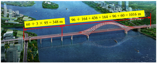
Figure 2.
The general layout of the Guangzhou Mingzhu Bay bridge.
The Mingzhu Bay steel bridge adopts a double orthotropic steel deck arrangement with a two-way eight-lane highway on the upper layer and sidewalks on both sides, as shown in Figure 3. The width of the main bridge panel is 43.2 m. The lanes are based on the median divider with a 2% inclination. Both sides of the lower deck are reserved for rail traffic dual lanes, and the pipeline channel is reserved in the middle. The thickness of the steel deck is 16 mm and U ribs are at every 600 mm spacing. The transverse diaphragm is placed every 3 m along the bridge.
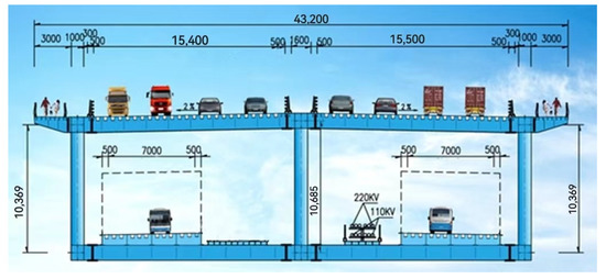
Figure 3.
The Layout of the upper and lower decks (mm).
3. Material and Methods
3.1. Design of OSD with the Arc-Shaped Stiffeners
Most of the fatigue cracks were found at the welded joint between the U rib and bridge deck panel [24,25]. To reduce the stress amplitude of the steel bridge panel, the arc-shaped stiffener was placed on the bridge deck panel where the welded joint of the U rib and bridge deck panel was located vertically. The stiffener was designed as a round arc-shaped structure and could be factory hot rolled with a steel deck panel. The arc height is 25 mm at maximum, and the concrete pavement layer is 55 mm, which is the same as the Mingzhu Bay bridge. To cover the joint area of the rib to the deck, the opening size of the arc is designed to be 150 mm, which was about 10 times the U rib welded seam. The design layout was based on the Mingzhu Bay steel bridge deck and is shown in Figure 4.
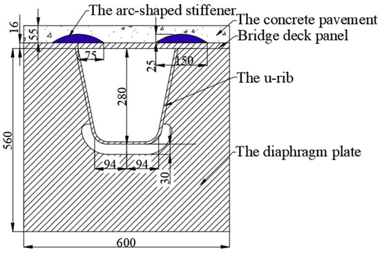
Figure 4.
The layout of the OSD with arc-shaped stiffener (mm).
3.2. Material
The steel deck of the Mingzhu Bay bridge is made of Q370qD steel, the elastic modulus of steel plate material is 206GPa, and Poisson’s ratio is 0.28. The chemical composition and mechanical properties are listed in Table 1 and Table 2. The arc-shaped stiffener also uses the same steel material as the steel deck in the FE model.

Table 1.
The chemical composition of Q370qD(%) [26].
Table 2.
The mechanical properties of Q370qD [26].
3.3. Finite Element Model
The 3D finite element bridge model was established by Midas/Civil, as shown in Figure 5. The whole model has 6676 nodes and 10,768 elements in total, which consist of 81 truss elements, 8067 beam elements, and 2620 shell elements. The finite element model of the 3 spans and 5 U-ribs bridge deck with/without arc-shaped stiffener was established, respectively, using Abaqus software. The C3D8 solid element was employed. The models were 9 m long from the longitudinal direction and 2.4 m wide from the transverse direction, as shown in Figure 5. The fixed constraint was applied at the bottom of the diaphragm plate.
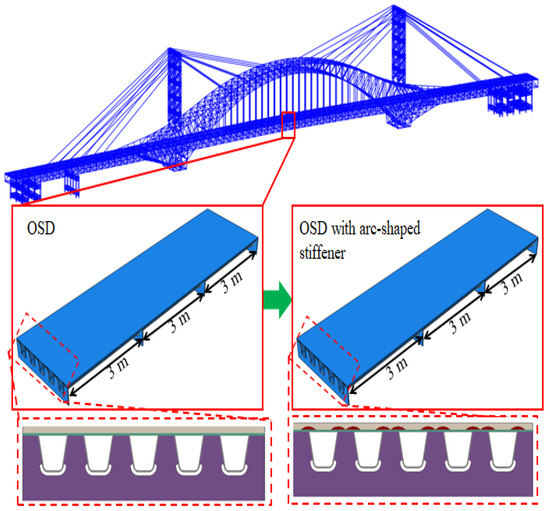
Figure 5.
Finite element model of the bridge deck.
In order to validate the FE model, the single U rib specimen under wheel load 150 kN was conducted to obtain the strains data from four different positions, as shown in Figure 6. The strain data were multiplied with Young’s modulus to obtain the stress at these positions. The same wheel load condition was applied to the FE model and the stress comparison was carried out, as listed in Table 3. The results shows the deviation is 10%, which shows a good agreement.
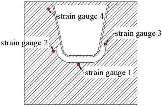
Figure 6.
Strain gauge arrangement [27].
Table 3.
Stress comparison.
The traffic flow was predicted based on the traffic volume statistics [28]. Vehicles are divided into seven fatigue vehicle models M1–M7 according to the axle number and axle load. The vehicle load statistics and traffic flow statistics are shown in Table 4.
Table 4.
Fatigue traffic model and traffic flow statistics [28].
According to the fatigue cracks that often occur in orthotropic steel bridge panels and considering the distribution of vehicle loads along the transverse position, the transverse loading can be divided into three loading conditions: on the U ribs, across the U rib, and on the middle of U ribs, as shown in Figure 7. Based on the literature [29,30], fatigue failure mainly occurs at the welding position between the U rib and deck panel and the welding position between the U rib and diaphragm. Moreover, the FE model was validated by fatigue tests in [27]. The two concern points were selected, as shown in Figure 7.
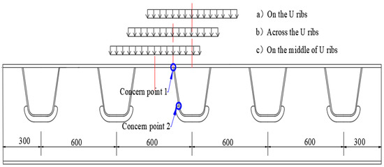
Figure 7.
Transverse loading condition along the bridge (mm).
3.4. Fatigue Life Evaluation
The fracture mechanics method was employed to analyze the steel deck in this study [10,31,32,33]. This method assumes the inevitable initial crack defect in the welded joint and the total fatigue life only counts the crack growth stage. The intensity factor amplitude of the crack tip is used to control the crack propagation and the Paris equation was established to describe the relationship between the crack growth rate and the intensity factor amplitude [34] in Equation (1):
where C and m are the material constants; ∆K is the stress intensity factor.
Concerning initial and critical crack sizes, the fatigue life of structural members or welded joints in the crack growth stage can be obtained by integrating the Paris Equation (1).
4. Results
4.1. Stress Analysis of Steel Bridge Panel
The Dload subroutine was programmed in Fortran based on the statics in Table 3, and the M1–M7 fatigue moving vehicle load was applied on the bridge model. To investigate the stress state of the OSD and OSD with arc-shaped stiffener steel deck, the fatigue vehicle models M1–M7 were loaded on the U-rib with a speed of 500 mm/s. The stress state of the fatigue vehicle model M7 loading is shown in Figure 8. See Table A1 in Appendix A for M1–M6 stress contours.
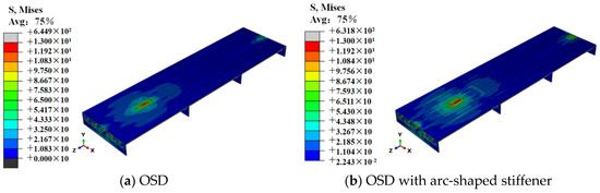
Figure 8.
The stress state of the steel bridge deck (MPa).
As shown in Figure 8, the stress amplitude of the OSD with the arc-shaped stiffener is lower compared with the OSD. However, the stress distribution of the OSD with the arc-shaped stiffener is more even in a wide range area due to the added stiffener. More area was employed to withstand the wheel load and the stress amplitude was reduced. When the fatigue vehicle models M1–M7 passed the FE model, the cyclic stress history of the two concern points on the steel deck was extracted for the following fatigue analysis. Additionally, the rain-flow counting method [35] was used to extract the stress amplitude and the number of cycles, as shown in Table 5.
Table 5.
Stress range and corresponding cycles of concern points.
4.2. Fatigue Life Evaluation
Based on the theory of fracture mechanics, the equivalent stress amplitude equation is listed in Equation (2). When the stress amplitude is smaller than the fatigue stress limit , fatigue failure will not occur [36]. As the stress amplitude is larger than the , , the equivalent stress amplitude is obtained from Equation (2).
where is the corresponding cycles; m is the material constant.
The fatigue limit of concern points is 28.34 MPa according to the China Highway Steel Bridge Code [37]. The stress amplitude value of concern points is listed in Figure 9.
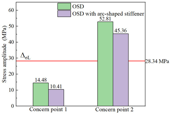
Figure 9.
Comparative analysis of maximum stress amplitude of concern.
As seen in Figure 9, the maximum stress amplitude of concern point 1 is less than the fatigue limit of 28.34 MPa. Concern point 1 assumes an infinite life without considering the fatigue life. The maximum stress of concern point 2 is greater than the fatigue limit, and the fatigue life was evaluated with the fracture mechanics method. The equivalent stress amplitude of concern point 2 is shown in Table 6.
Table 6.
Equivalent stress amplitude.
The stress amplitude in Paris Equation (1) is expressed by equivalent stress amplitude, and Equation (3) can be obtained as follows:
where is the critical crack length; N is the fatigue life when the initial crack extends to the critical crack length .
The initial crack length was recommended as 0.1–0.5 mm [38,39]. In this study, the initial crack length was 0.1–0.5 mm, and the critical crack was 0.8 times the thickness. When the crack length a/plate width is <0.1, the solution of the infinite plate is adopted, and the crack stress intensity factor: is Y = 1.12. According to the steel fracture toughness and crack propagation rate [40], for structural steel, m = 3, . As the C, m, Y, , and values are put into Equation (3), the fatigue life of concern points can be obtained under different initial crack lengths, as shown in Table 7.
Table 7.
The fatigue life of concern.
5. Discussion
5.1. Impact of the Arc-Shaped Stiffener on Stress Amplitude
To study the impact of the arc-shaped stiffener, the fatigue stress state of the proposed OSD with arc-shaped stiffener and OSD was studied under a moving vehicle load. A comparative study was conducted with OSD to investigate the fatigue stress amplitude and stress distribution mechanism. The dynamic response of concern point 1 and 2 under seven fatigue moving vehicle models M1–M7 was extracted from numerical results, as shown in Figure 10.
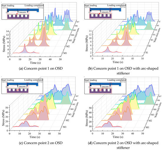
Figure 10.
Dynamic response of OSD with/without stiffener.
As seen in Figure 10, at concern point 2, the stress amplitude of the OSD with the arc-shaped stiffener is about 15% lower than the OSD, especially at the maximum stress. While the stress of concern point 2 is significantly greater than that of concern point 1, the stress state is almost the same as the OSD.
5.2. Impact of the Arc-Shaped Stiffener on Fatigue Life
The fatigue life of the OSD and OSD with arc-shaped stiffener was evaluated with an initial crack from 0.1–0.5 mm. The fatigue stress of concern point 1 was smaller than the fatigue stress limit, therefore, fatigue performance was not considered. The fatigue life of concern point 2 was evaluated based on the fracture mechanics method, and different fatigue lives were obtained by assuming different initial cracks, as shown in Figure 11.
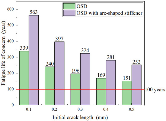
Figure 11.
Fatigue life evaluation.
As seen in Figure 11, the fatigue life of the bridge panel gradually decreases as the initial crack gradually increases. Furthermore, the fatigue life of the OSD with the arc-shaped stiffener is higher than the OSD.
In general, the stress state and distribution on the bridge deck are extremely crucial for fatigue performance. When the vehicles pass the bridge, the bridge deck panel will generate different cyclic stress cycles. The stress amplitude is smaller than the limit, which is 28.34 MPa, therefore, the fatigue performance is not considered. Once the stress amplitude reaches the limit, it will trigger the fatigue life evaluation. To enhance fatigue resistance, reducing the stress amplitude in terms of improving the stress distribution is the efficient and economical way. However, the stress distribution on the bridge panel is related to its geometric structure. From the structural point of view, the proposed steel bridge deck can reduce the stress amplitude and employ more area on the deck to withstand the moving wheel load with the arc-shaped stiffener on the bridge deck. Different moving vehicle loads only affect the stress amplitude, not the stress distribution. Furthermore, the welding process may cause stress concentration and it will have a serious impact on fatigue life evaluation. Hence, the stiffener was recommended with a prefabricated molding process.
6. Conclusions
In this paper, the newly designed OSD with the arc-shaped stiffener was proposed and studied through numerical analysis. The fatigue performance was studied under the seven fatigue moving vehicle load. The fatigue stress state and distribution mechanism were analyzed. With the arc-shaped stiffener, the stress amplitudes of the proposed steel bridge panel were reduced by 15% with common OSD. The stress distribution was more even in a wider range area. The fatigue life of the proposed bridge panel was enhanced by 40% compared with common OSD. Therefore, the proposed OSD with the arc-shaped stiffener can alleviate the fatigue crack propagation and enhance the fatigue resistance of steel bridge panels.
During the past decades, most of the long-span steel bridges adopted OSD due to its efficiency. However, the typical fatigue crack failure of OSD is always a challenge for bridge engineers after years of service, and it endanger the safety of the steel bridge. The proposed steel bridge deck can reduce the stress amplitude and extend the maintenance period to achieve better cost-effective goals compared with the common OSD. It has great potential for application in the future.
Author Contributions
P.L. wrote the manuscript, Y.C. and H.L. provided the ideas, thinking, and data processing, and J.Z., L.A. and Y.W. provided the fund. All authors have read and agreed to the published version of the manuscript.
Funding
Science and Technology Research and Development Project of China Railway Construction Bridge Engineering Bureau Group Co., Ltd. (DQJ-2018-A01); Tianjin Science and Technology Development Plan Project (19YDLZSF00030).
Data Availability Statement
Not applicable.
Acknowledgments
The authors would like to thank China Railway Construction Bridge Engineering Bureau Group Co., Ltd. for the funding support.
Conflicts of Interest
The authors declare no conflict of interest.
Appendix A
Stress contours of OSD and OSD with the arc-shaped stiffener under fatigue moving vehicle load (M1–M6).
Table A1.
Stress state of steel bridge deck under moving vehicle M1–M6 (MPa).
Table A1.
Stress state of steel bridge deck under moving vehicle M1–M6 (MPa).
| Vehicle Model Type | (1) OSD | (2) OSD with the Arc-Shaped Stiffener |
|---|---|---|
| M1 |  |  |
| M2 |  |  |
| M3 |  |  |
| M4 |  |  |
| M5 |  |  |
| M6 |  |  |
References
- Huang, Y.; Zhang, Q.; Bao, Y.; Bu, Y. Fatigue assessment of longitudinal rib-to-crossbeam welded joints in orthotropic steel bridge decks. J. Constr. Steel Res. 2019, 159, 53–66. [Google Scholar] [CrossRef]
- Zhang, X.; You, Y.C.; Kong, D.R.; Chen, T.; Zhang, J.R. An analytical investigation into the vibration behavior of an orthotropic steel deck. J. Vib. Control 2022, 5, 6. [Google Scholar] [CrossRef]
- Siwowski, T.; Kulpa, M.; Janas, L. Remaining Fatigue Life Prediction of Welded Details in an Orthotropic Steel Bridge Deck. J. Bridge Eng. 2019, 12, 05019013. [Google Scholar] [CrossRef]
- Kainuma, S.; Young, J.S.; Yang, M.; Inokuchi, S. Welding residual stress in roots between deck plate and U-rib in orthotropic steel decks. Measurement 2016, 92, 475–482. [Google Scholar] [CrossRef]
- Fang, H.; Iqbal, N.; Van Staen, G.; De Backer, H. Experimental and Numerical Investigation of Stress Concentration atRib-to-Crossbeam Joint. Int. J. Steel Struct. 2021, 21, 360–380. [Google Scholar] [CrossRef]
- Zeng, Z. Classification and cause analysis of typical fatigue cracks in orthotropic steel bridge panels. Steel Struct. 2011, 26, 9–15+26. (In Chinese) [Google Scholar]
- Su, Q.; Xie, H. Summary of steel structure bridge construction of Hong Kong-Zhuhai-Macao Bridge. China J. Highw. Trans. 2016, 29, 1–9. (In Chinese) [Google Scholar] [CrossRef]
- Di, J.; Ruan, X.Z.; Zhou, X.H.; Wang, J.; Peng, X. Fatigue assessment of orthotropic steel bridge decks based on strain monitoring data. Eng. Struct. 2021, 228, 111437. [Google Scholar] [CrossRef]
- Cui, C.; Zhang, Q.; Luo, Y.; Hao, H.; Li, J. Fatigue reliability evaluation of deck-to-rib welded joints in OSD considering stochastic traffic load and welding residual stress. Int. J. Fatigue 2018, 111, 151–160. [Google Scholar] [CrossRef]
- Xiang, C.; Wang, D.L.; Wang, B.J.; Chen, A.R.; Ma, R.J. Numerical simulation of root-deck crack propagation of orthotropic steel bridge deck. Struct. Infrastruct. Eng. 2022, 18, 1076–1090. [Google Scholar] [CrossRef]
- Zhang, Q.H.; Li, J.; Guo, Y.W.; Yuan, D.Y.; Bu, Y.Z. Fatigue failure modes and resistance evaluation of orthotropic steel bridge panel structures. China Civ. Eng. J. 2019, 52, 71–81. (In Chinese) [Google Scholar]
- Li, D.T.; Zhang, C.G.; Lu, P.M. Fatigue Property and Improvement of a Rounded Welding Region between the Diaphragm Plate and Closed Rib of an Orthotropic Steel Bridge Deck. Metals 2020, 1, 161. [Google Scholar] [CrossRef]
- Gou, H.; Shi, X.; Zhou, W.; Cui, K.; Pu, Q. Dynamic performance of continuous railway bridges: Numerical analyses and field tests. Proc. Inst. Mech. Eng. Part F J. Rail Rapid Transit 2018, 232, 936–955. [Google Scholar] [CrossRef]
- Chen, Y.X.; Lv, P.M.; Li, D.T. Research on Fatigue Strength for Weld Structure Details of Deck with U-rib and Diaphragm in Orthotropic Steel Bridge Deck. Metals 2020, 9, 484. [Google Scholar] [CrossRef]
- Bu, Y.Z.; Jin, Z.K.; Huang, Y.; Zhang, H.; Xu, G.Y. Key Influencing factors of Fatigue Crack Propagation in Longitudinal Rib Roof of Steel Bridge Panel. China J. Highw. Transp. 2019, 32, 61–70. (In Chinese) [Google Scholar]
- Jiang, C.; Long, X.Y.; Han, X.; Liu, J. A Method for Crack Growth Path Analysis of Random Crack Structures. Chin. J. Solid Mech. 2014, 35, 30–38. (In Chinese) [Google Scholar]
- Maljaars, J.; Bonet, E.; Pijpers, R.J.M. Fatigue resistance of the deck plate in steel orthotropic deck structures. Eng. Fract. Mech. 2018, 201, 214–228. [Google Scholar] [CrossRef]
- Maliaars, J.; Steenbergen, H.M.G.M.; Vrouwenvelder, A.C.W.M. Probabilistic Model for Fatigue Crack Growth and Fracture of Welded Joints in Civil Engineering Structures. Int. J. Fatigue 2012, 38, 108–117. [Google Scholar] [CrossRef]
- Xiao, Z.; Yamada, K.; Ya, S.; Zhao, X. Stress analyses and fatigue evaluation of rib-to-deck joints in steel orthotropic decks. Int. J. Fatigue 2008, 30, 1387–1397. [Google Scholar] [CrossRef]
- Yu, B.; Qiu, H.; Wang, H.; Guo, T. Experimental research on fatigue behavior and damage development of welded conformation of orthotropic steel bridge deck. J. Highw. Transp. Res. Dev. 2009, 26, 64–69. [Google Scholar] [CrossRef]
- Guo, J.; Hang, D.; Zhu, X. Prediction of Crack Propagation in U-Rib Components Based on the Markov Chain. J. Bridge Eng. 2020, 25, 04020089. [Google Scholar] [CrossRef]
- Heng, J.; Zheng, K.; Gou, C.; Zhang, Y.; Bao, Y. Fatigue performance of rib-to-deck joints in orthotropic steel decks with thickened edge U-ribs. J. Bridge Eng. 2017, 22, 04017059. [Google Scholar] [CrossRef]
- Hu, H.; Zhao, J.; Ren, Y.; An, L.; Liu, Y. Overall design of main bridge of mingzhu bay bridge. Bridge Constr. 2021, 51, 93–99. (In Chinese) [Google Scholar]
- Van den Berg, N.; Xin, H.; Veljkovic, M. Effects of residual stresses on fatigue crack propagation of an orthotropic steel bridge deck. Mater. Des. 2021, 198, 109294. [Google Scholar] [CrossRef]
- Xu, W.; Zhu, Z.; Niu, H. Study on Fatigue Cracking of Longitudinal rib-panel Reinforced with CFRP for orthotropic Steel Bridge Panels. J. Railw. Sci. Eng. 2021, 18, 2933–2943. (In Chinese) [Google Scholar]
- GB/T 714-2015; Bridge Structural Steel. National Standards of the People’s Republic of China: Beijing, China, 2015.
- Liu, P.; Chen, Y.; Lu, H.; Zhao, J.; An, L.; Wang, Y.; Liu, J. Fatigue Analysis of Long-Span Steel Truss Arched Bridge Part I: Experimental and Numerical Study of Orthotropic Steel Deck. Metals 2022, 12, 1117. [Google Scholar] [CrossRef]
- Liu, P.; Lu, H.; Chen, Y.; Zhao, J.; An, L.; Wang, Y.; Liu, J. Fatigue Analysis of Long-Span Steel Truss Arched Bridge Part II: Fatigue Life Assessment of Suspenders Subjected to Dynamic Overloaded Moving Vehicles. Metals 2022, 12, 1035. [Google Scholar] [CrossRef]
- Chen, Y.; Lv, P.; Li, D. Study on detail fatigue strength of welded structure between U rib and diaphragm. Bridge Constr. 2014, 44, 63–68. (In Chinese) [Google Scholar]
- Geng, X.; Yang, A. Influence factors of Residual Stress at U-rib Welding of Steel Bridge Panel. J. Railw. Sci. Eng. 2022, 45, 56–60. (In Chinese) [Google Scholar]
- Hobbacher, A. Recommendations for Fatigue Design of Welded Joints and Components IIW Doc, 2nd ed.; IIW 2259-15; Springer: Berlin/Heidelberg, Germany, 2016. [Google Scholar]
- Ye, X.; Su, Y.; Han, J. A State-of-the-Art Review on Fatigue Life Assessment of Steel Bridge. Math Probl. Eng. Vol. 2014, 2014, 956473. [Google Scholar] [CrossRef]
- Luo, P.; Zhang, Q.; Bao, Y.; Bu, Y. Fatigue performance of welded joint between thickened edge U-rib and deck in orthotropic steel deck. Eng. Struct. 2019, 181, 699–710. [Google Scholar] [CrossRef]
- Irwin, G.R.; Liebowitz, H.; Paris, P.C. A mystery of fracture mechanics. Eng. Fract. Mech. 1968, 1, 235–236. [Google Scholar] [CrossRef]
- Lee, Y.L.; Tjhung, T. Rainflow Cycle Counting Techniques. Met. Fatigue Anal. Handb. 2012, 89–114. [Google Scholar] [CrossRef]
- Zhang, Y.; Li, Y.; Zhang, D. Fatigue Life Estimation of Rib-to-Deck Joints in Orthotropic Steel Decks. Adv. Mat. Res. 2011, 163–167, 410–416. [Google Scholar] [CrossRef]
- JTG D64-2015; Code for Design of Highway Steel Structure Bridges. National Standards of the People’s Republic of China: Beijing, China, 2015.
- BS7910; Guide on Methods for Assessing the Acceptability of Flaws in Metallic Structures. British Standard Institution: London, UK, 2013.
- Radaj, D.; Sonsino, C.M.; Fricke, W. Fatigue Assessment of Welded Joints by Local Approaches; Woodhead Publishing: Cambridge, UK, 2006. [Google Scholar]
- Sedlacek, G.; Stranghoner, N.; Kuhn, B.; Hoffmeister, B.; Dahl, P.; Langenberg, P.; Kalinowski, B.; Bleck, W.; Mannsfeld, A.; Brozetti, J.; et al. Composite Bridge Design Improvement for High-Speed Railways; Office for Official Publications of the Europen Cmmunities: Luxembourg, 2001. [Google Scholar]


Publisher’s Note: MDPI stays neutral with regard to jurisdictional claims in published maps and institutional affiliations. |
© 2022 by the authors. Licensee MDPI, Basel, Switzerland. This article is an open access article distributed under the terms and conditions of the Creative Commons Attribution (CC BY) license (https://creativecommons.org/licenses/by/4.0/).