Article

Analysis and Characterization of the Weld Pool and Bead Geometry of Inconel 625 Super-TIG Welds

1
Department of Materials System Engineering, Pukyong National University, Busan 48513, Korea
2
Super-TIG Welding Co., Limited Busan 48513, Korea
*
Author to whom correspondence should be addressed.
Metals 2020, 10(3), 365; https://doi.org/10.3390/met10030365
Submission received: 5 February 2020 / Revised: 5 March 2020 / Accepted: 10 March 2020 / Published: 11 March 2020

Abstract

:
The welding market is changing globally, becoming eco-friendly, robotized and automated. The tungsten inert gas welding (TIG) process is indispensable in industries that require high-quality welds with the absence of spatter and fumes. However, the production rate of TIG welding is very low, which limits its many applications. The present study introduces a novel TIG welding method called super-TIG welding. Super-TIG welding is able to produce a high production rate of welds compared to other fusion welding methods. In super-TIG welding, the novel C-type filler is used, which is different from the conventional TIG welding of circular wire. The relations of the heat input ratio in super-TIG welding to weld pool length and weld bead geometry were measured using the Inconel 625 C-filler. Two types of deposition techniques were used for a bead-on-plate welds, such as stringer beads and oscillation beads. The weld pool and bead geometry measurements are found to be different between stringer beads and oscillation bead techniques. The length of the molten pool and bead size were higher for oscillation beads over the stringer beads. These changes were associated with the difference in heat transfer contact area and bead height.

1. Introduction

In recent years, the welding market has been changing toward environmental-friendliness and complete automation with high production. TIG welding is an eco-friendly welding process with no spatter or fumes, and is a welding process capable of producing reliable welds [1]. However, its applications are restricted to limited industries due to its low productivity [2]. In order to improve the productivity of TIG welding, it is necessary to increase the current and increase the welding speed. However, under high-current TIG welding, discontinuous beads and undercuts can be formed due to the impact of strong arc pressure on the base metal [3,4,5,6].
Lin and Eagar [3] have identified that the effect of arc pressure at the center region is directly proportional to the TIG current. The increase in welding current leads to the high pressure at the center of the arc and tends to form the defects. It was reported that the importance of arc current and its length in the TIG welding decide the range of arc power [4]. Oh et al. [5] have investigated the spreading of current density in the arc by the output of the arc pressure. Mendez et al. [6] reported the demerits of the use of high welding current in TIG welding regarding the quality of the weld bead appearance. Therefore, studies were focused on arc characteristic improvements and performance of the arc pressure by developing various methods. Initially, some researchers tried the application of an external magnetic effect to regulate the arc characteristics and increased the travel speed to enhance the productivity of the welding [7].
High energy TIG arc welding is one of the recently developed methods by modifying the TIG welding with the controlling of arc space by compressing and constraining the arc. Therefore, the arc energy and arc ionization change to release the arc heat dissipation [8]. Some studies proved that activated TIG (A-TIG) welding could effectively improve productivity by enhancing the penetration depth by arc constriction and the Marangoni effect [9]. Further improvements in TIG welding led to the development of the magnetic, enriched, keyhole gas tungsten arc welding (GTAW) process. By using a point magnetic field system selected with permanent magnetic poles surrounded by water cooling, the arc shape was modified to control the arc characteristics of welding to reduce the total heat in the welds [10]. To reduce the heat input in TIG welding, a low current welding process was developed by the addition of the hot wire [11]. All of these techniques were focused on process modification. It is expensive and needs an implementation of modified types of equipment according to the applications. Most recently, a high productivity method developed in TIG welding by changing the shape of the circular section to a C-shape was called super-TIG welding [12,13,14].
In this study, super-TIG welding is applied for bead-on-plate (BOP) welds with the Inconel 625 C-Filler. The objective of this paper is to clarify the relation of heat input ratio and bead geometry, penetration depth and molten pool length in GTAW. Two different deposition techniques were applied for the welds—stringer beads and oscillation beads. The molten pool length was measured for each deposition technique. Similarly, the penetration depth and height also were measured.

2. Materials and Methods

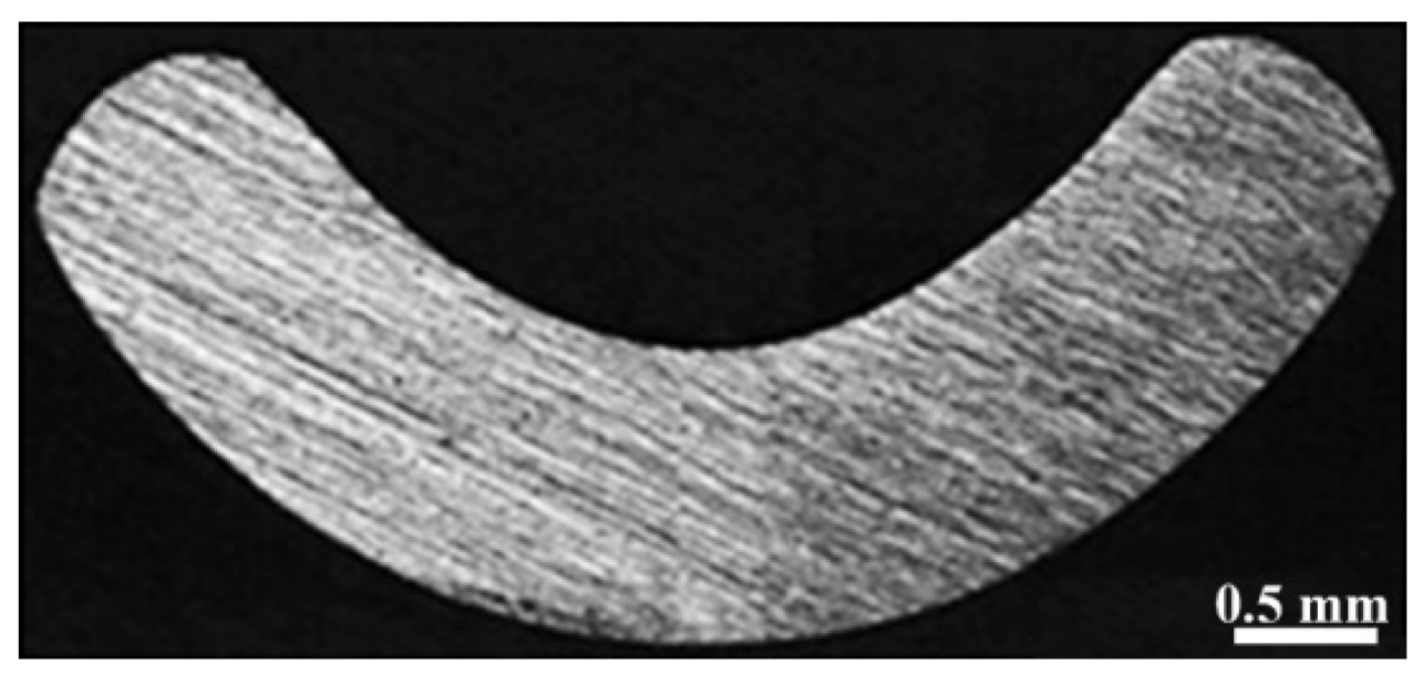
The materials of the SS400 (ASTM A283) plate with a thickness of 10 mm were used for the present study. The bead-on-plate welds were produced on the SS400 plate using Inconel 625 C-Filler. The chemical compositions of the SS400 and C-Filler are given in Table 1. The process setup and C-Filler position are shown in Figure 1. The C-Filler was used as a consumable wire to deposit the weld beads instead of circular wire. The cross-sectional view of the C-Filler is presented in Figure 2. The experiments were carried out using stringer (non-OS) beads and oscillation (OS) beads. The welding
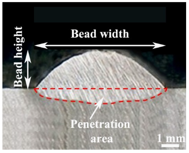
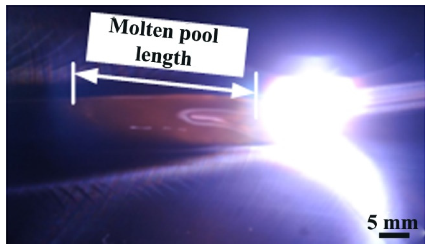
Parameters for the stringer bead and oscillation bead weld tests are presented in Table 2. During welding, the welding current was kept constant and the feed rate was altered to change deposition area (DA) and deposition rate (DR). The width also increased at a constant oscillation frequency of 3.5 Hz. The molten pool was recorded for every condition to determine the weld pool characteristics using a Nikon camera, (Nikon, Tokyo, Japan). The camera setup conditions are given in Table 3. In order to calculate the heat input ratio (HR), we used the measured current, voltage and feed rate of the feeder by connecting the welding waveform monitoring system to the TIG welding machine. The heat input ratio was calculated from the welding current, voltage, travel speed and deposition area (current and voltage were measured by waveform monitoring system, Monitech, Republic of Korea) as per the Equations (1) and (2). Figure 3 exhibits the macrostructure with the measuring procedure for the penetration area, bead width, bead height and average penetration. The penetration is expressed as the average penetration (AP) by dividing the penetration area (PA) by the bead width, as per the Equation (3). Figure 4 depicts the schematic diagram for the measurement of the melt pool length from the images recorded using the camera. The length of the molten pool was expressed as the length from the end of the arc diameter to the region not solidified.
Heat   input   ( kJ mm ) = Voltage ( V ) × Current ( A ) × 60 Travel   speed ( S )   ( mm min ) × 1000  
Heat   input   ratio   ( kJ mm 3 ) = Heat   input   ( kJ mm ) Depostion   area   ( mm 2 )
Average   penetration   ( mm ) = Penetration   area Bead   width

3. Results

3.1. Sringer Bead Test (Non-OS)

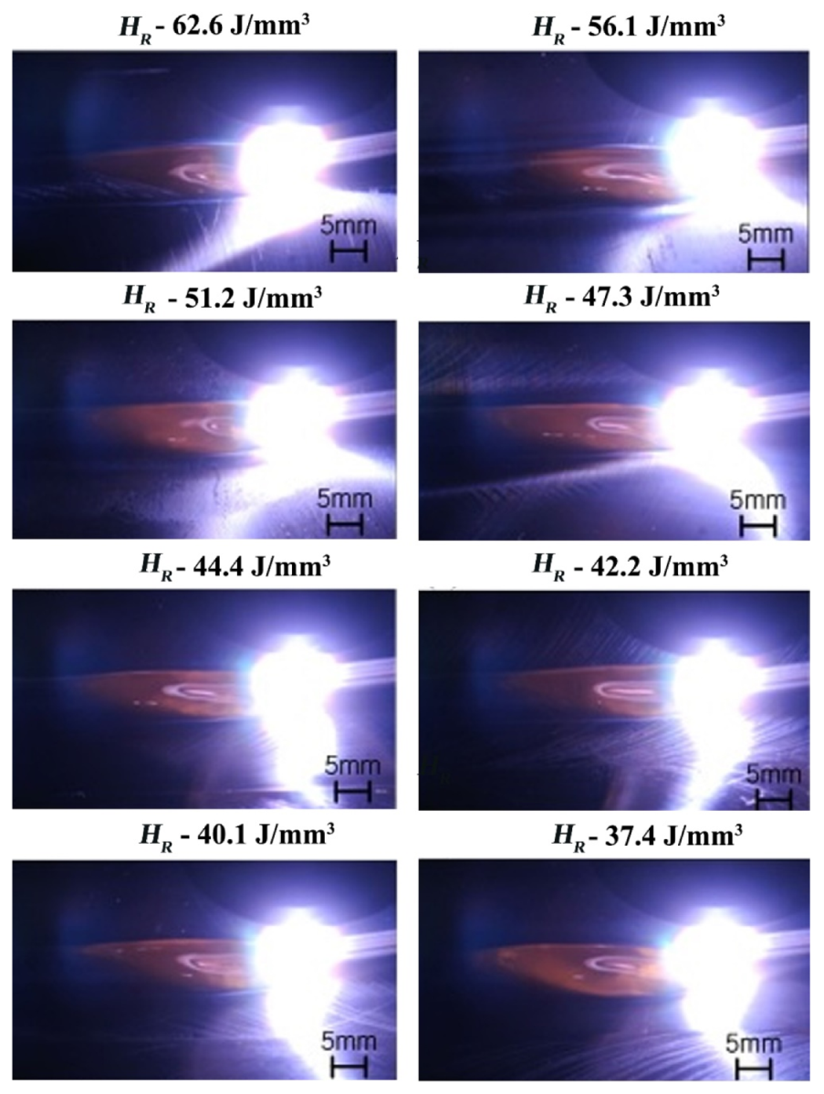
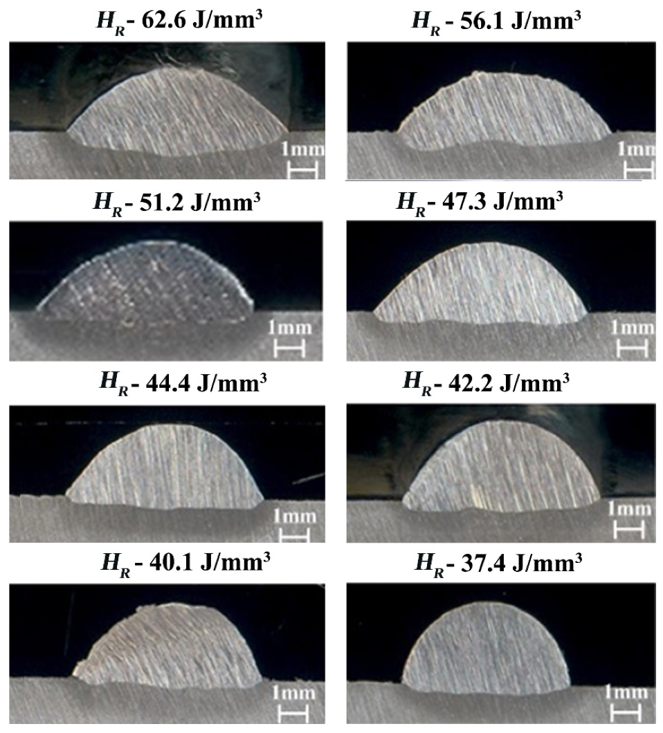
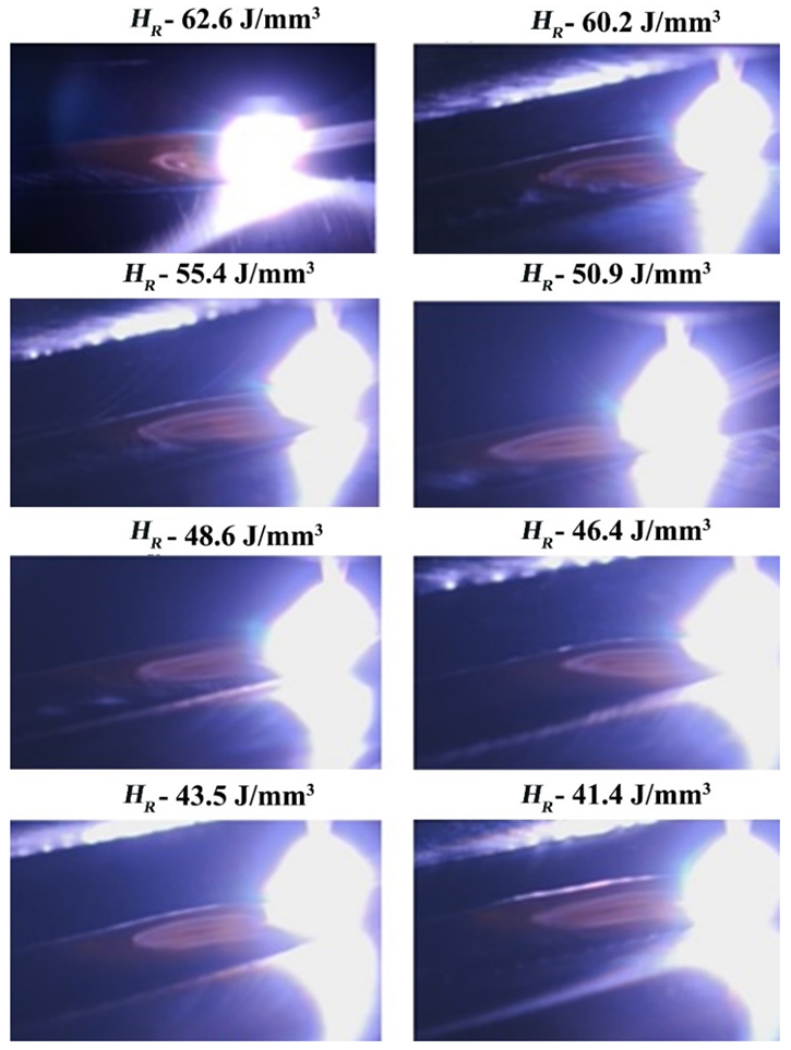
Figure 5 illustrates the molten pool characteristics according to the heat input ratio. The heat input ratio value varied in order to determine the changes in the weld pool. When the welding current and welding speed are constant, the C-Filler feed rate is increased. Hence, the deposition area also increased; then, the heat input ratio value decreased. As the heat input ratio decreases, the welding voltage decreases gradually due to the increase in feed rate and deposition area. It was considered that the increase of feed rate led to the increase of bead height and decrease in welding voltage. As the bead height increases, the distance between the tungsten electrode and the molten metal becomes smaller [15]. The molten pool length was expected to decrease with the decrasing of heat input ratio, but the results determined an increase in molten pool length [16]. Figure 6 shows the cross-sections of the macrostructure according to HR for the stringer bead welds. It was observed that the decrease in heat input ratio resulted in decreasing average penetration and bead width, but the bead height increased. The heat transfer contact area between the molten pool and base metal is directly propotional to the heat input ratio, and it decreases with the decreasing of HR. The thermal conductivity of the Inconel 625 is lower. Therefore, the accumulation of heat in the weld pool is intended to increase the molten pool length. Consequently, the heat input ratio is a governing parameter for weld pool length and bead geometry. The desired welding conditions to obtain the required weld bead geometry can be easily determined by the heat input ratio in super-TIG welding.
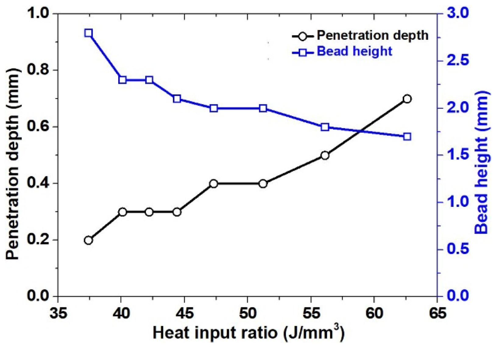
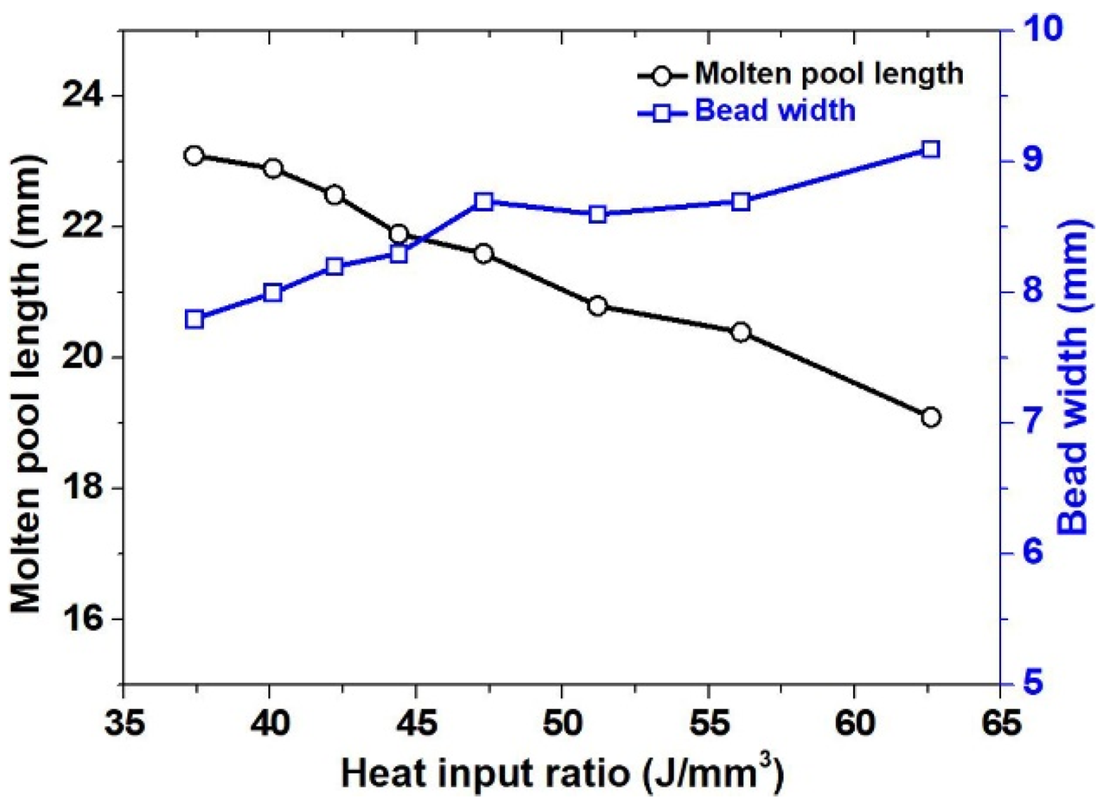
Figure 7 shows the results of penetration and bead height, according to HR, in the stringer bead tests. The bead height tends to increase, and the penetration becomes shallow, with the decreasing of the heat input ratio; this is due to the increase of the deposition area (see Equation (2)). At higher deposition rates, most of the heat input is consumed for melting the filler metal; therefore, the melting of the base metal is minimal. Figure 8 illustrates the results of molten pool length and bead width according to the HR. The bead width decreases and the molten pool length increases with the decreeasing of the heat input ratio. When the heat input ratio decreased, the molten pool length was expected to be short due to the consumption of a large amount of heat input to melt the filler metal, but it we saw an increase. That is due to the fact that the experiment was conducted with a BOP Test. The decreasing of heat input ratio causes a decrease in bead width and the heat transfer contact area to the base material, such that the molten metal solidification becomes slower, thereby increasing length. The decreasing of bead width is because of the consumption of a large amount of heat for the melting of the high speed filler metal. The lesser effect of heat on the base material cannot melt its surface deeply; hence, the wettability becomes lowered [17].

3.2. Oscilaltion Bead Test

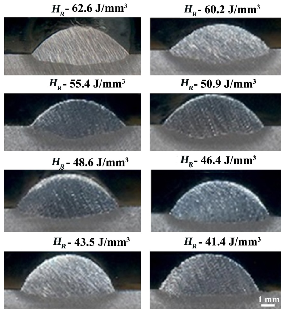
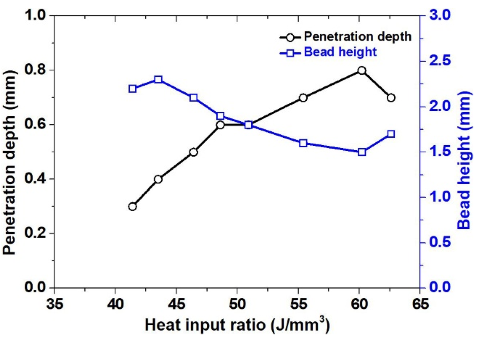
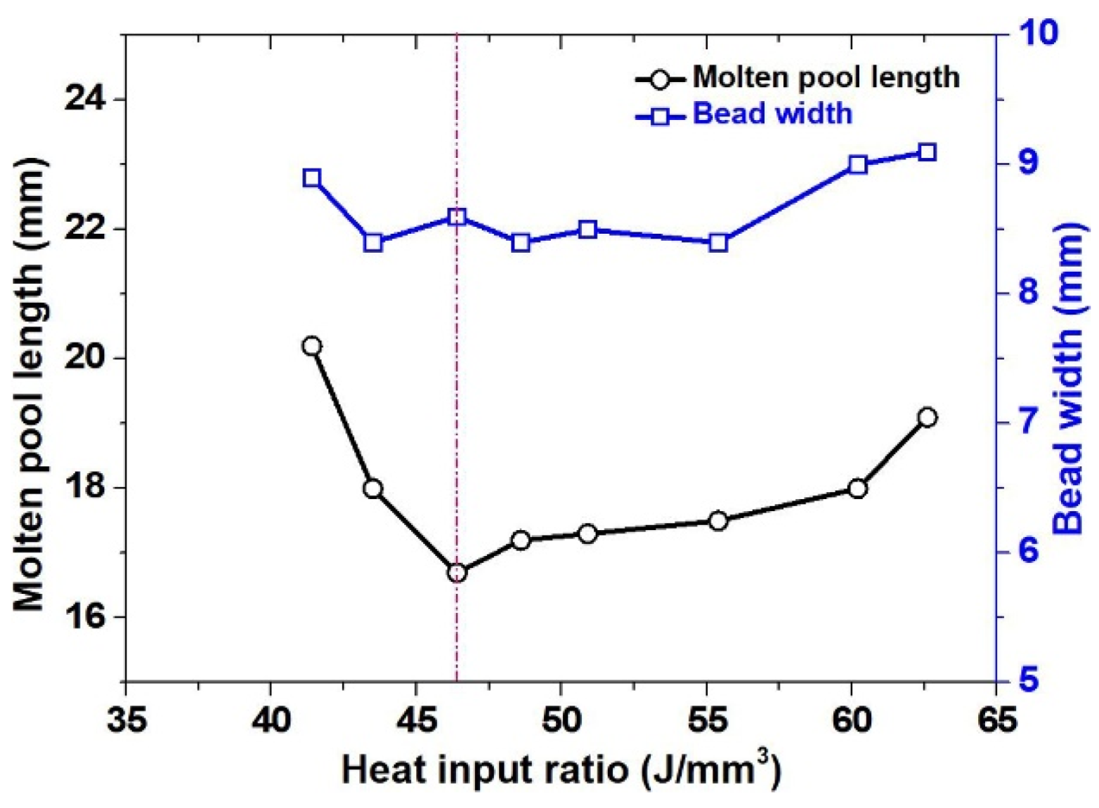
The oscillation bead test results revealed the differences in welding voltage. In general, the voltage remains constant, even through the decreasing of HR, unlike the result of the stringer bead test. Because of the OS, the average voltage was considered to be constant, even though the HR is lower. Figure 9 shows the photograph of the molten pool length according to HR in the OS test. The molten pool length decreased and increased again with the decreasing of heat input ratio. Figure 10 shows the cross-sectional macrostructure according to HR of the OS test. The decreasing of HR has resulted in a decrease in bead width and penetration and an increase of bead height. The bead width was found to be within 10% for oscillation beads. Figure 11 illustrates the penetration and bead height, according to HR in the OS test. In this test, even though the HR is smaller, the bead height becomes larger and reduces the penetration depth. Figure 12 shows the results of the molten pool length and bead width, according to HR. Since the bead width was maintained at a constant level through the OS, the bead width did not vary within 10%. As HR decreased, the molten pool length initially tended to decrease, but increased from the HR 46.4 J/mm3. This means that if the HR lowers to a certain level, the bead height becomes higher. It is considered that the molten pool length becomes longer due to the slow heat transfer. The heat transfer from the molten metal reduces after reaching a certain level at which the higher bead heights form [18]. The heat transfer contact area also increases with the atmosphere/air, but its effect on solidification is minimal compared to the base metal; that is due to the lower thermal conductivity of Inconel 625. Moreover, constant heat input to the molten pool by the TIG arc cannot enable the air to make large changes in the solidification of the molten pool.
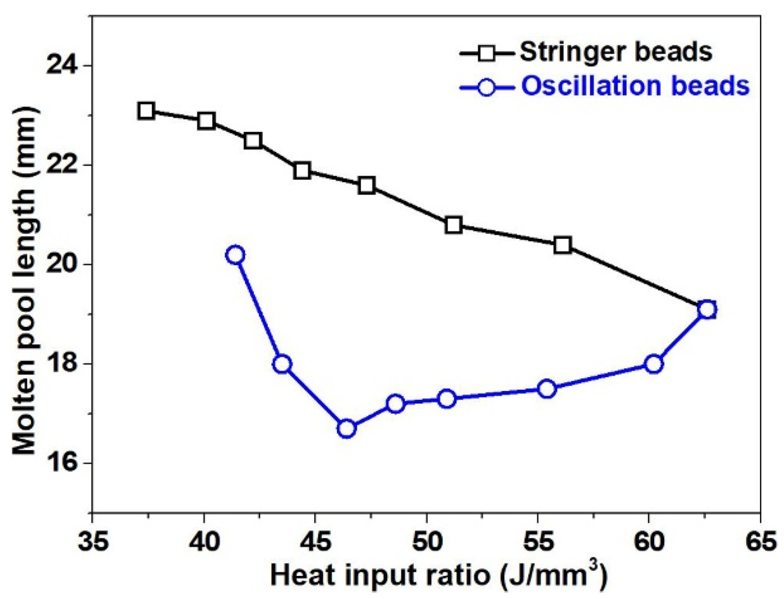
Figure 13 shows the results of the molten pool length of stringer and OS bead tests, according to HR. The comparison of the plots between stringer beads and oscillation beads evidenced the differences in the solidification of the molten pool and bead geometry. Figure 14 shows a schematic diagram of the heat transfer contact area. Figure 14a shows a small contact area, whereas Figure 14b shows a large contact area. In the case of the stringer beads, when the HR is decreased, then the heat input consumption for melting the C-Filler increased. Hence, the melting of the base material is decreased so that the bead width decreases and the bead height becomes higher. Because of the higher bead height, the molten pool length becomes longer. The increase in bead height decreases the distance between the substrate and the molten pool. Thus, the heat transfer contact area reduces and the molten pool length increases. In the case of OS, molten pool length decreases with the decreasing of HR, and it tends to increase again. It is considered that the increase in the molten pool is due to the wettability limitation of the base material when the HR is above a certain level. In the case of grooved welding or fillet welding with a large contact area, the HR becomes smaller, so the length of the molten pool will decrease. Additionally, in wire arc additive manufacturing, it may affect the resolution by inducing the flow of metal [14], unlike the power ratio used to control hot cracking and dilution in the nuclear power plants. Therefore, HR is considered to be a better parameter for setting the welding conditions due to considering the welding speed and deposition area [18,19,20,21].

4. Conclusions

Super-TIG welding was used for the measurement of molten pool length and bead geometry of BOP welds with Inconel 625 C-type filler. The heat input ratio (HR) was defined as the ratio of heat input to the deposition area. The results are as follows:
1) In the stringer bead test, the bead width and penetration decreased and the molten pool length tended to increase as HR decreased. The increase of molten pool length is caused by the reduction of heat transfer contact area and the increase of bead height.
2) In the oscillation bead test, bead width is nearly constant, even though the HR decreases, but penetration decreases as the HR decreases. The smaller the HR over 46 J/mm3, the shorter the molten pool length. However, in the low region of HR under 46 J/mm3, molten pool length increases as the HR decreases because of bead height increase.

Author Contributions

Conceptualization, J.H.P., M.C. and S.M.C.; methodology, M.C. and S.M.C.; investigation, J.H.P. and M.C.; writing—original draft preparation, M.C.; writing – review and editing, M.C.; validation, J.H.P. and M.C. All authors have read and agreed to the published version of the manuscript.

Funding

This research received no external funding.

Conflicts of Interest

The authors declare no conflict of interest.

References

  1. Baghel, P.K.; Nagesh, D.S. Multiattribute Assessment of Consumables for TIG Welding of Aluminum Alloys. Int. J. Manuf. Eng. 2016, 2016, 1–9. [Google Scholar] [CrossRef] [Green Version]
  2. Lathabai, S.; Jarvis, B.L.; Barton, K.J. Keyhole gas tungsten arc welding of commercially pure zirconium. Sci. Technol. Weld. Join. 2008, 13, 573–581. [Google Scholar] [CrossRef]
  3. Lin, M.L.; Eagar, T.W. Pressures produced by gas tungsten arcs. Metall. Trans. B 1986, 17, 601–607. [Google Scholar] [CrossRef]
  4. Savage, W.F.; Nippes, E.F.; Agusa, K. Effect of arc force on defect formation in GTA welding. Weld. J. 1979, 58, 212–224. [Google Scholar]
  5. Oh, D.S.; Kim, Y.S.; Cho, S.M. Derivation of current density distribution by arc pressure measurement in GTA welding. Sci. Technol. Weld. Join. 2005, 10, 442–446. [Google Scholar] [CrossRef]
  6. Mendez, P.F.; Niece, K.L.; Eagar, T.W. Humping formation in high current GTA welding. In Proceedings of the International Conferences on Joining of Advanced and Specialty Materials II., Cincinnati, OH, USA, 1–4 November 1999; pp. 151–158. [Google Scholar]
  7. Nomura, K.; Ogino, Y.; Hirata, Y. Shape control of TIG arc plasma by cusp type magnetic field with permanent magnets. Weld. Int. 2012, 26, 759–764. [Google Scholar] [CrossRef]
  8. Wu, H.; Yunlong, C.; Qiang, M.; Dan, L. Research advances in high-energy TIG arc welding. Int. J. Adv. Manuf. Technol. 2019, 104, 391–410. [Google Scholar] [CrossRef]
  9. Venkatesan, G.; Muthupandi, V.; Justine, J. Activated TIG welding of 304L using mono-and tri-component fluxes. Int. J. Adv. Manuf. Technol. 2017, 93, 329–336. [Google Scholar] [CrossRef]
  10. Liu, Z.; Shi, Y.C.; Xin, Y.; Qi, Z.; Tao, Z.; Zhen, L. Magnetic-enhanced keyhole TIG welding process. Int. J. Adv. Manuf. Technol. 2018, 99, 275–285. [Google Scholar] [CrossRef]
  11. Silwal, B.; James, W.; Daniel, W. Hot-wire GTAW cladding: Inconel 625 on 347 stainless steel. Int. J. Adv. Manuf. Technol. 2019, 102, 3839–3848. [Google Scholar] [CrossRef]
  12. Park, J.H.; Kim, Y.H.; Baek, H.J.; Cho, S.M. A study on process development of super-TIG welding for 9% nickel steel with Alloy 625. J. Manuf. Processes 2019, 40, 140–148. [Google Scholar] [CrossRef]
  13. Ho, J.J.; Park, J.H.; Cheepu, M.; Cho, S.M. Observation and analysis of metal transfer phenomena for high-current super-TIG welding process. Sci. Technol. Weld. Join. 2020, 25, 106–111. [Google Scholar] [CrossRef]
  14. Cho, S.M.; Son, M.S.; Park, J.H. Development of welding quality monitoring method for TIG cladding. J. Weld. Join. 2014, 31, 90–95. [Google Scholar] [CrossRef] [Green Version]
  15. Wahab, M.A.; Painter, M.J.; Davies, M.H. The prediction of the temperature distribution and weld pool geometry in the gas metal arc welding process. J. Mater. Process. Technol. 1998, 77, 233–239. [Google Scholar] [CrossRef]
  16. Mukherjee, T.; Wei, H.L.; De, A.; DebRoy, T. Heat and fluid flow in additive manufacturing–Part II. Comput. Mater. Sci. 2018, 150, 369–380. [Google Scholar] [CrossRef]
  17. Welding and Repair Technology Center, Measures to Minimize 52M Hot Cracking on Stainless Steel Base Materials; EPRI: Palo Alto, CA, USA, 2012; p. 1025167.
  18. McCracken, S.L.; Smith, R.E. Behavior and hot cracking susceptibility of filler metal 52 M overlays on cast austenitic stainless steel base materials. In Hot Cracking Phenomena in Welds III; Böllinghaus, T., Lippold, J., Cross, C.E., Eds.; Springer: Berlin, Germany, 2011; pp. 333–352. [Google Scholar] [CrossRef]
  19. Venukumar, S.; Cheepu, M.; Babu, T.V.; Venkateswarlu, D. TIG arc welding-brazing of dissimilar metals-An Ooverview. Mater. Sci. Forum 2019, 969, 768–774. [Google Scholar] [CrossRef]
  20. Venukumar, S.; Cheepu, M.; Babu, T.V.; Venkateswarlu, D. Cold metal transfer (cmt) welding of dissimilar materials: An overview. Mater. Sci. Forum 2019, 969, 685–690. [Google Scholar] [CrossRef]
  21. Cheepu, M.; Lee, C.I.; Cho, S.M. Microstructural characteristics of wire arc additive manufacturing with Inconel 625 by super-TIG welding. Trans. Indian. Inst. Met. (in press). [CrossRef]
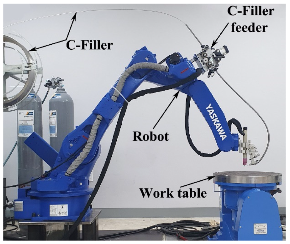
Figure 1. Super-TIG welding process setup.
Metals 10 00365 g001
Figure 2. A cross-section of the C-Filler for super-TIG welding.
Metals 10 00365 g002
Figure 3. Definition and measurement of bead geometryF.
Metals 10 00365 g003
Figure 4. Definition and measurement of molten pool length.
Metals 10 00365 g004
Figure 5. Molten pool length according to heat input ration of stringer bead test.
Metals 10 00365 g005
Figure 6. Cross-section results of stringer bead test.
Metals 10 00365 g006
Figure 7. Penetration and bead height according to HR for the stringer bead test.
Metals 10 00365 g007
Figure 8. Molten pool length and bead width according to HR for the stringer bead test.
Metals 10 00365 g008
Figure 9. Molten pool length according to heat input ration of stringer bead test.
Metals 10 00365 g009
Figure 10. Cross-sectional results of the oscillation bead test.
Metals 10 00365 g010
Figure 11. Penetration and bead height according to HR for the oscillation bead test
Metals 10 00365 g011
Figure 12. Molten pool length and bead width according to HR for the oscillation bead test.
Metals 10 00365 g012
Figure 13. Graph of molten pool length by HR.
Metals 10 00365 g013
Figure 14. Schematic of heat transfer according to the contact area of the (a) stringer bead; (b) the oscillation bead.
Metals 10 00365 g014
Table 1. Chemical composition of the SS400 and of C-Filler.
MaterialCSiMnPSCrNi
SS400 Base Metal0.1550.1630.4550.0070.0090.0190.0101
Inconel 625 C-Filler0.100.500.5023.058.010.05.0
Table 2. Super-TIG welding conditions used for stringer bead and oscillation bead tests.
Base MetalSS400 (50 mm × 150 mm × 10 mm)
Filler MetalInconel 625(C-Filler, 5mm2)
Shield Gas (L/min)20 (Ar 93% + H2 7% )
Arc Length (mm)5
Current (A)300
Welding Speed (cm/min)50
Experiment No.12345678
Feed Rate (cm/min)125135145155165175185195
Deposition Area DA (mm2)13.814.916.017.118.219.320.421.5
Deposition Rate DR (kg/h)3.33.63.84.14.44.64.95.1
Oscillation Test
Oscillation Width (mm)01.82.43.03.64.24.85.4
Frequency (Hz)3.5-------
Table 3. Weld pool measuring camera conditions.
CameraNikon—V1
LensAF MICRO NIKKOR 105 mm
FilterUV 62 mm + ND2-2000 52 mm
Lens to work distance (mm)350
Filming angle (o)−37o
Shutter1/640, F14