Article

The Influence of Electron Beam Treatment on the Structure and Properties of the Surface Layer of the Composite Material AlMg3-5SiC


1
Hubei Digital Textile Equipment Key Laboratory, Wuhan Textile University, Wuhan 430073, China
2
Mechanical Engineering Technologies Faculty, Bauman Moscow State Technical University, 105005 Moscow, Russia
3
Baikov Institute of Metallurgy and Materials Science, Russian Academy of Sciences, 119334 Moscow, Russia
4
Department of Metal Technology, Moscow Power Engineering Institute, 111250 Moscow, Russia
*
Authors to whom correspondence should be addressed.
Lubricants 2026, 14(2), 50; https://doi.org/10.3390/lubricants14020050
Submission received: 18 December 2025 / Revised: 20 January 2026 / Accepted: 23 January 2026 / Published: 25 January 2026

Abstract

The influence of electron beam treatment parameters (electron gun speed, electron beam current, scanning frequency, and sweep type) on the structure and properties of the surface layer of the composite material AlMg3-5SiC has been investigated. Composite specimens of AlMg3 alloy reinforced with 5 wt.% silicon carbide particles were manufactured via the stir casting process. Experimentally, processing modes with heat input from 120 to 240 J/mm yield a modified layer thickness from 74 to 1705 µm. Heat input should not exceed 150 J/mm to ensure a smooth and defect-free surface layer. The macro- and microstructure were examined using optical microscopy. Brinell hardness was measured. Friction and wear tests were performed under dry sliding friction conditions using the “bushing on plate” scheme. This evaluated the tribological properties of the composite material in its original cast state and after modifying treatment. Due to the matrix alloy structure refinement by 5–10 times, the surface layer’s hardness increases by 11% after treatment. The modified specimens have superior tribological properties to the initial ones. Wear rate reduces by 17.5%, the average friction coefficient reduces by 32%, and the root mean squared error of the friction coefficient, which measures friction process stability, reduces by 50% at a specific load of 2.5 MPa. Therefore, the electron beam treatment process is a useful method for producing high-quality and uniform wear-resistant aluminum matrix composite surface layers.

1. Introduction

Modern developments in mechanical engineering are associated with the creation of powerful and economical machines and mechanisms. These machines and mechanisms place high demands on the service properties, reliability, and durability of their most critical components [1]. Plain bearings are among the components that determine the service properties of machines and mechanisms [2]. Plain bearings can experience significant thermal and cyclic loads during operation, as well as intensive wear and corrosion [3]. Currently, antifriction materials based on tin, copper, or aluminum are used in plain bearing designs. However, their service properties have largely reached their limit values [4,5]. Therefore, it is impossible to further increase the maximum operating loads and sliding speeds of plain bearings without using alternative functional materials. One possible solution is to use particle-reinforced composite materials (CMs) as antifriction materials for plain bearings. CMs are heterophase materials. They consist of a highly plastic metal matrix (alloys of aluminum, tin, copper, titanium, etc.) and uniformly distributed refractory high-modulus micron-sized reinforcements [6,7]. The combined action of these heterogeneous components creates a new material. Its physical, mechanical, and tribological properties differ quantitatively and qualitatively from those of the components and traditional structural materials [8,9,10]. CMs are widely used in various industries, including aerospace, automotive, shipbuilding, and electronics. Aluminum matrix CMs account for 69% of the total [11,12]. This is due to their high characteristics (electrical and thermal conductivity, heat capacity, damping capacity, plasticity, strength, etc.) [13,14]. Aluminum alloys are almost three times lighter than tin or copper alloys. This ensures the low weight of CMs based on them [15,16].
With the appropriate selection of the matrix alloy composition, size, proportion, and type of reinforcement, aluminum matrix composite materials (AMCs) have low friction coefficient values, as well as high wear resistance and scuff resistance over a wide temperature range [17,18,19,20]. Reinforcing particles help improve the microhydrodynamics of the friction process [20,21]. In this case, the soft structural component in such AMCs is a solid solution based on aluminum, and high-strength reinforcing particles act as supporting components, reducing the friction coefficient values over a wide range of loading parameters [22,23]. Thus, using AMCs as an antifriction material can alter the operating conditions and significantly expand the plain bearing applications.
AMCs are primarily manufactured using casting technology, which provides a better combination of mechanical and tribological properties compared to solid-phase methods [24,25,26,27,28]. Additionally, surface modification is another way to achieve high service properties in AMCs (mechanical, tribological, and others). The surface of structural materials, including AMCs, can be modified through strain hardening (e.g., rolling, vibration-impact hardening, explosive processing, electromechanical processing, friction processing, ultrasonic vibration processing, etc.), by processing with concentrated energy sources (e.g., electron or laser beams, welding arc in a magnetic field, microplasma processing, etc.), or by diffusion application of alloying elements (e.g., carburization, boriding, cyanidation, nitriding, etc.) [29,30,31,32,33,34].
Among these techniques, surface modification using concentrated energy sources, such as an electron beam [35,36,37], a laser beam [38,39,40], or an electric arc in a magnetic field [41], is promising for AMCs. These modification techniques involve local heating of a surface area due to concentrated energy flow, followed by ultra-high cooling due to heat removal into the specimen’s internal layers. Using a laser beam or electric arc as the heating source provides cooling rates of 105 K/s [40] and 103 K/s [41], respectively. The maximum cooling rates are 105 K/s and 109 K/s, respectively, in continuous and pulsed modes during electron beam processing [36]. These rates lead to significant refinement of the matrix alloy structure and also improvement of surface layer properties. Concentrated heat sources are efficient due to their high energy flow density, localized impact, and ability to transfer energy to the treatment area without contact. The heating and cooling rates, as well as the duration that the material remains at high temperatures, can be regulated by adjusting the parameters of the surface treatment. This enables the achievement of the required thickness and structure of the surface layer, along with its corresponding properties. In particular, the thickness of the modified layer during electron beam processing of the 2024 aluminum alloy reached 100 μm [37]. For the AlSi12Cu2NiMg-TiCN AMC system, the thickness ranged from 100 to 150 μm [35]. AlSi9Mg-20SiC AMC laser beam processing produced a modified layer with a thickness of 185 to 410 μm [40]. During the processing of the AlSi9 aluminum alloy with an electric arc, the thickness of the modified layer reached 1200 µm [41]. However, such a depth of penetration and a significant volume of the liquid pool require longer crystallization times. This prevents the achievement of high cooling rates. Another feature of electron beam processing is that electrons can penetrate to a depth of several tens of micrometers. This depth depends on the accelerating voltage and the properties of the material being processed. Consequently, the maximum level of heat generation occurs in the subsurface layer, in contrast to other concentrated heat sources that only heat the surface being treated [31,42,43,44].
Modern electron guns (e-guns) are equipped with electromagnetic deflection systems. These systems enable the electron beam to move along a given trajectory with virtually no inertia at high speeds, which are inaccessible to mechanical movement systems, used in electric arc and laser beam processing. Additionally, electron beam scanning allows for the redistribution of power density, increasing the surface cooling rate and positively affecting the modified layer structure [36,42]. Aluminum matrix alloys have a high tendency to form pores due to their high chemical reactivity with gases. The intense fluidity of the liquid metal also affects the bead’s formation [37,44]. Gas protective environments used during surface modification with a laser beam or electric arc cannot always provide the necessary degree of protection to prevent the formation of defects. Electron beam treatment is carried out in a vacuum environment with a vacuum level of at least 10−3 Pa. It ensures intensive degassing of the liquid metal and reduces the amount of dissolved gases [44]. Additionally, the high reflectivity of aluminum alloy surfaces complicates laser beam surface modification. However, the electron beam is insensitive to the reflective properties of the material being processed [43]. Due to these features, the electron beam treatment has great potential for surface modification of AMCs. However, the wide range of AMC compositions and the small number of studies devoted to modifying their surfaces make research on each specific combination of matrix aluminum alloy and reinforcement novel and necessary. Thus, investigating the influence of electron beam treatment parameters (e-gun speed, electron beam current, scanning frequency, and sweep type) on the structure and properties (mechanical and tribological) of the surface layer of the AlMg3-5SiC composite material is a very important task. The objective of this study was to accomplish that task.

2. Materials and Methods

Composite materials based on the aluminum alloy AlMg3 reinforced with 5 wt.% silicon carbide (SiC) particles with an average size of 14 μm were subjected to electron beam treatment. The chemical composition of the AlMg3 matrix alloy is provided in Table 1. This matrix alloy of the Al-Mg system was selected due to its excellent weldability and increased resistance to oxidation and corrosion. The high plasticity of this matrix alloy allows for the use of pressure treatment methods in the manufacturing of plain bearing elements from AMCs. The silicon carbide particles were selected based on the criteria of low cost, availability, and demand. A proportion (5 wt.%) ensures the absence of intensive wear of mating parts in friction units, as demonstrated in previous studies [12,31].

2.1. Material Preparation

The initial AMC specimens were produced using liquid-phase casting technology under laboratory conditions. This method provides a better combination of mechanical and tribological properties compared to solid-phase methods [26,28]. The specimens were plates 20 × 50 × 8 mm. The composite melt was manufactured using an inexpensive stir casting process [25,45]. Previously, a layer of K-Al-F and Na-Al-F flux systems was applied to the surface of the matrix melt to remove or dissolve the oxide film and adsorbed gases. This increased the wettability of the SiC particles by the matrix melt, ensuring their penetration beneath the melt surface. The reinforcing particles were kept in an oven at a temperature of (823–873) K for 2 h for drying, burning out random organic contaminants, and oxidizing free silicon. Then they were introduced into the matrix melt for (45–60) s. The matrix melt was stirred using an impeller at a frequency of 600 min−1. The 50 mm in diameter impeller had 2 blades and was immersed to a depth of 1/3 of the melt height. The matrix melt temperature was (1073–1123) K. After the reinforcing particles were fed, the stirring process was continued for 15 to 20 s. Then, the impeller was removed from the crucible. The composite melt was held at this temperature for 20 min. The oxide film was removed from the surface to reduce the amount of gas inclusions. Then, the composite melt was re-stirred and cast into a chill mold.

2.2. Electron Beam Treatment

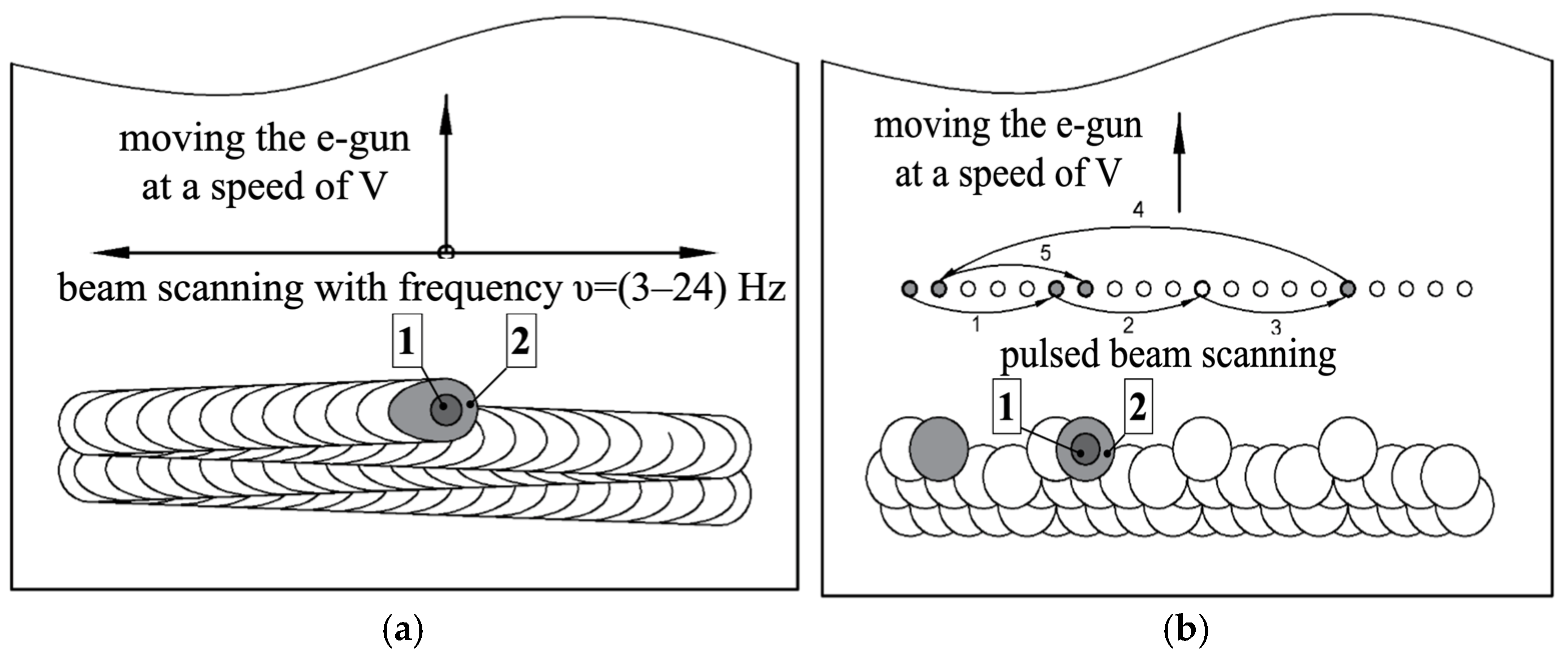
Surface modification was performed using an AELTK-344-12 electron beam equipment, JSC “NITI “Progress”, Izhevsk, Russia in a vacuum environment of 10−3 Pa. To determine the process parameters that ensure the formation of a high-quality, continuous, modified surface layer with overlapping melted zones, the electron beam treatment was carried out under the following conditions: e-gun speed (V)—from 120 to 1200 mm/min; the electron beam current (I)—from 6 to 40 mA; the scanning frequency (υ)—from 3 to 24 Hz. The accelerating voltage (U) was set at a constant 60 kV. To account for the thermal influence of the previously processed beads and the specimen’s heating, two experimental schemes were tested (Figure 1).
-
With a straight sweep. In this sweep type, the electron beam scans the specimen surface from one edge to the other and back, guided by the magnetic system. It then returns to its starting position, and the cycle repeats. The e-gun moves along the specimen. Meanwhile, the electron beam scans transversely with a frequency of 3–24 Hz (Figure 1a).
-
With a pulse sweep. In this sweep type, the cooling rate of the processed layer increases due to the electron beam’s movement with a certain step between points. The thermal impact of the adjacent point is limited by skipping and then returning to the adjacent point, according to the scheme in Figure 1b. The e-gun moved continuously at a constant speed to ensure the technical feasibility. The electron beam was deflected in a pulse sweep along the direction of movement to compensate for the e-gun’s movement and ensure the formation of an even bead perpendicular to its movement.
The electron beam treatment parameters are provided in Table 2. The scanning frequency was selected in such a way as to ensure 50% overlap of the beads at a given e-gun speed. The width of the treatment zone was 22 mm in all cases. This allowed studying the macro- and microstructure and performing friction and wear tests on the modified surface layers.
The value of heat input value Q, J/mm, which characterizes the amount of heat introduced per unit length of the processed bead, was determined by:
Q = (U × I × 10−3)/(V/60),
where U is the accelerating voltage (U = 60 kV); I is the electron beam current, mA; V is the e-gun speed, mm/min.

2.3. Macro- and Microstructural Characterisation

After electron beam treatment, the specimens were cut perpendicular to the direction of treatment and polished using standard metallographic methods. The macro- and microstructure of the modified surface layers was examined using a Zeiss Observer Z1m optical microscope, Carl Zeiss AG, Oberkochen, Germany with AxioVision version 4.9 image analysis software. The specimens were etched with Keller’s reagent, which had the following composition: 2.5% HNO3, 1.5% HCl, 1% HF, and 95% H2O. The etching was performed for 10 s at a temperature of 293 K (room temperature). The thickness of the modified layer was determined on transverse sections of the manufactured specimens using optical microscopy. Additionally, the surface quality of the specimens after electron beam treatment was examined, as a sufficient level can eliminate the need for subsequent mechanical treatment.

2.4. Hardness and Tribological Properties

The hardness of the specimens in their initial and treated states was measured using the Brinell method (HB) on a stationary hardness tester, HBRVU-187.5, TIME Group Inc., Beijing, China. A spherical indenter with a diameter of 2.5 mm was pressed into the specimen surface under increasing axial load. Once the load reached a maximum of 625 N, it was held for 20 s. The imprint diameter was measured after the load was removed. Hardness measurements were carried out at least 10 points on each specimen’s surface to ensure the reliability of the obtained results.
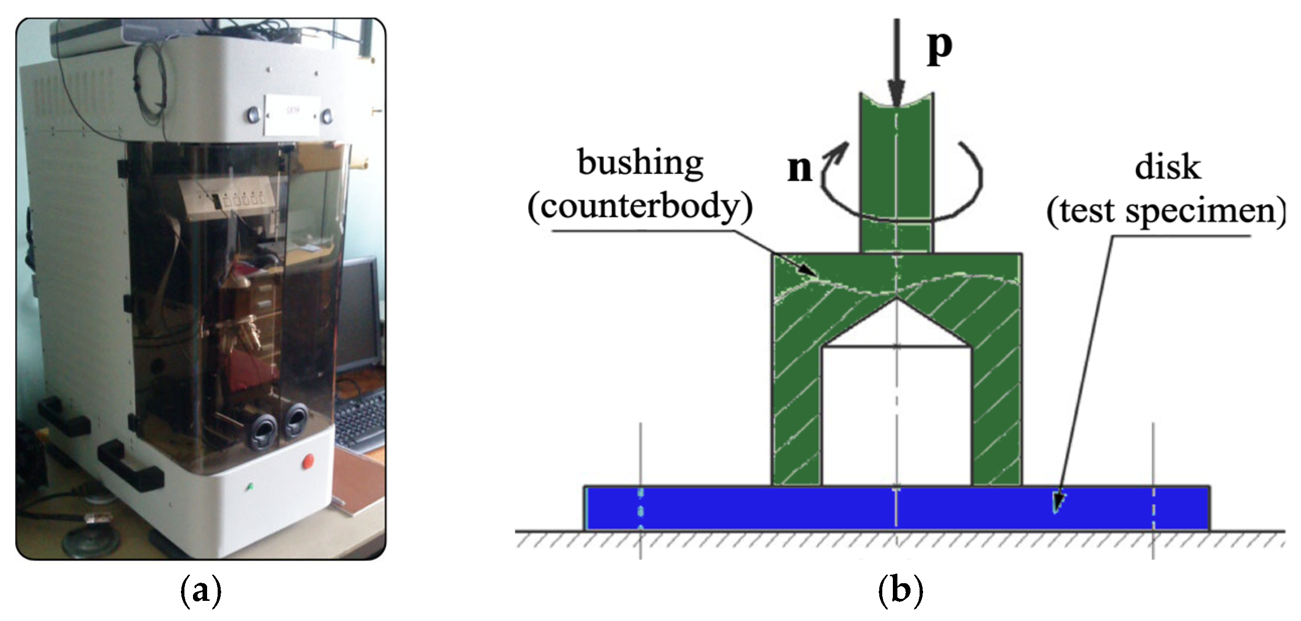
Dry sliding friction and wear tests were performed on initial cast specimens and after electron beam treatment to evaluate the effectiveness of the surface modification. The tests were performed using a universal CETR UMT Multi-Specimen Test System, Bruker, Billerica, USA using the “bushing (counterbody, hardened steel 40X, GOST 4543, HRC > 45) on plate (specimen)” scheme (Figure 2). This test scheme is characterized by a mutual overlap coefficient of one, replicating the operation of most real friction units [46]. The dimensions of the steel bushing are an inner diameter of 12 mm and an outer diameter of 16 mm. The selected testing method involved continuously loading the specimens stepwise at a constant sliding velocity (V) of 0.5 m/s and a wide range of specific loads (p): 0.5, 1.0, 1.5, 2.0, and 2.5 MPa. The tests were carried out for 600 s at each specific load. The total loading time was 3000 s, and the total friction distance was 1500 m. Friction and wear tests were performed under normal conditions (room temperature 293 ± 1 K and humidity 60 ± 4%). Each test was carried out on three specimens processed by an electron beam in the same mode.
The friction coefficient was recorded continuously in real time during dry sliding friction and wear tests. The average friction coefficient (f), as well as the root mean squared error (σ), which characterizes the stability of the friction process, were automatically calculated using the obtained values with the UMT TestViewer version 2.16 software. The specimens’ mass loss was measured by weighing them on an analytical balance after completion of the full cycle of dry sliding friction and wear tests. Specimen wear was assessed using the mass wear rate, Im × 10−5, g/m:
Im = ∆/L,
∆ = m1 − m2,
where ∆ is the loss of mass of the specimen; m1 is the mass of the specimen before testing; m2 is the mass of the specimen after testing; L is the total friction distance.
The results of the hardness and tribological property measurements were averaged, and confidence intervals were determined.

3. Results and Discussion

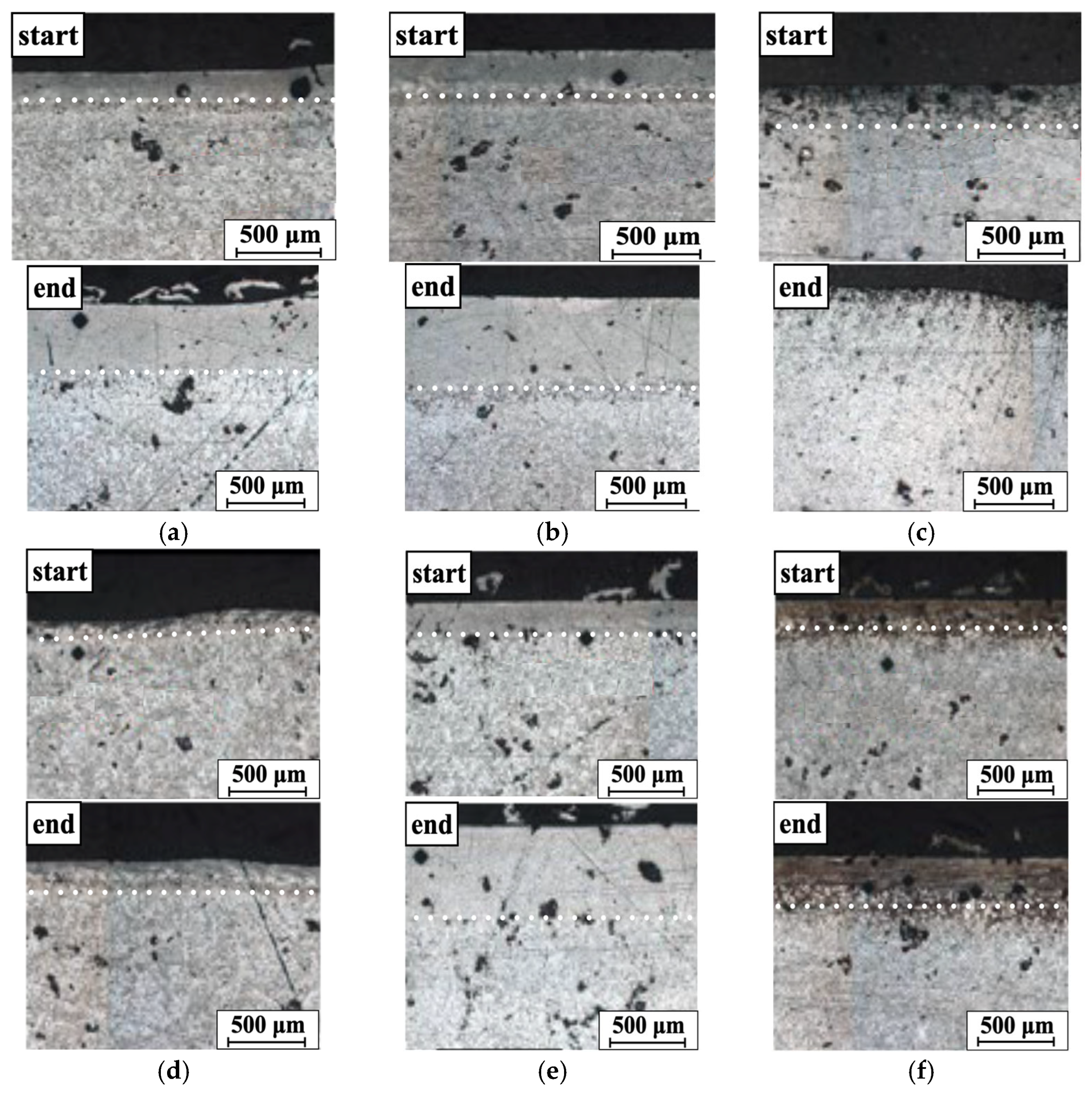
Table 3 and Figure 3 show the thickness measurement results and macrostructure images of the modified layers, respectively. As can be seen, an increase in the thickness of the processed surface layer at the end of the bead is observed for all tested modes. This increase is due to non-stationary conditions (small volume and short lifetime of the molten pool), as well as the resulting decrease in the temperature gradient caused by heating of the processed specimen during electron beam treatment. A significant increase in the thickness of the modified layer is observed at low values of the e-gun speed (V) (compare processing modes 3 and 6 in Table 3). Repeated electron beam treatment while maintaining the mode parameters increased the modified layer thickness threefold, from 74 to 223 µm and from 178 to 611 µm at the start and end of the layer, respectively (compare processing modes 4 and 5 in Table 3). Additionally, with the same heat input values, electron beam treatment with straight sweep results in a greater modified layer thickness compared to processing with a pulse sweep (compare processing modes 2 and 4 in Table 3). This is due to the shorter lifetime and increased cooling rate of the molten pool when using a pulse sweep scheme.
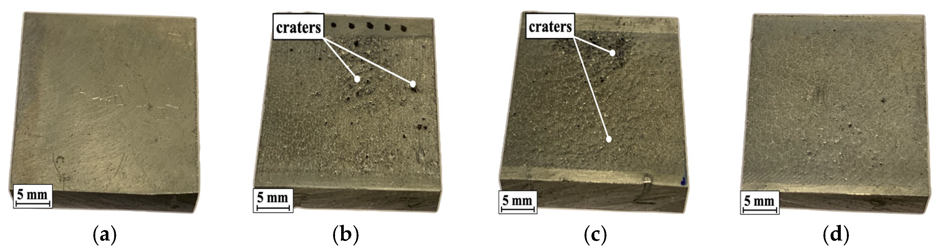
The surface quality of specimens processed in modes with heat input greater than 150 J/mm is worse than the initial cast state due to the formation of surface discontinuities in the form of craters and other imperfections (compare Figure 4a–c). Processing modes with less than 150 J/mm of heat input allow for the formation of smooth, defect-free AMC layer surfaces (Figure 4d).
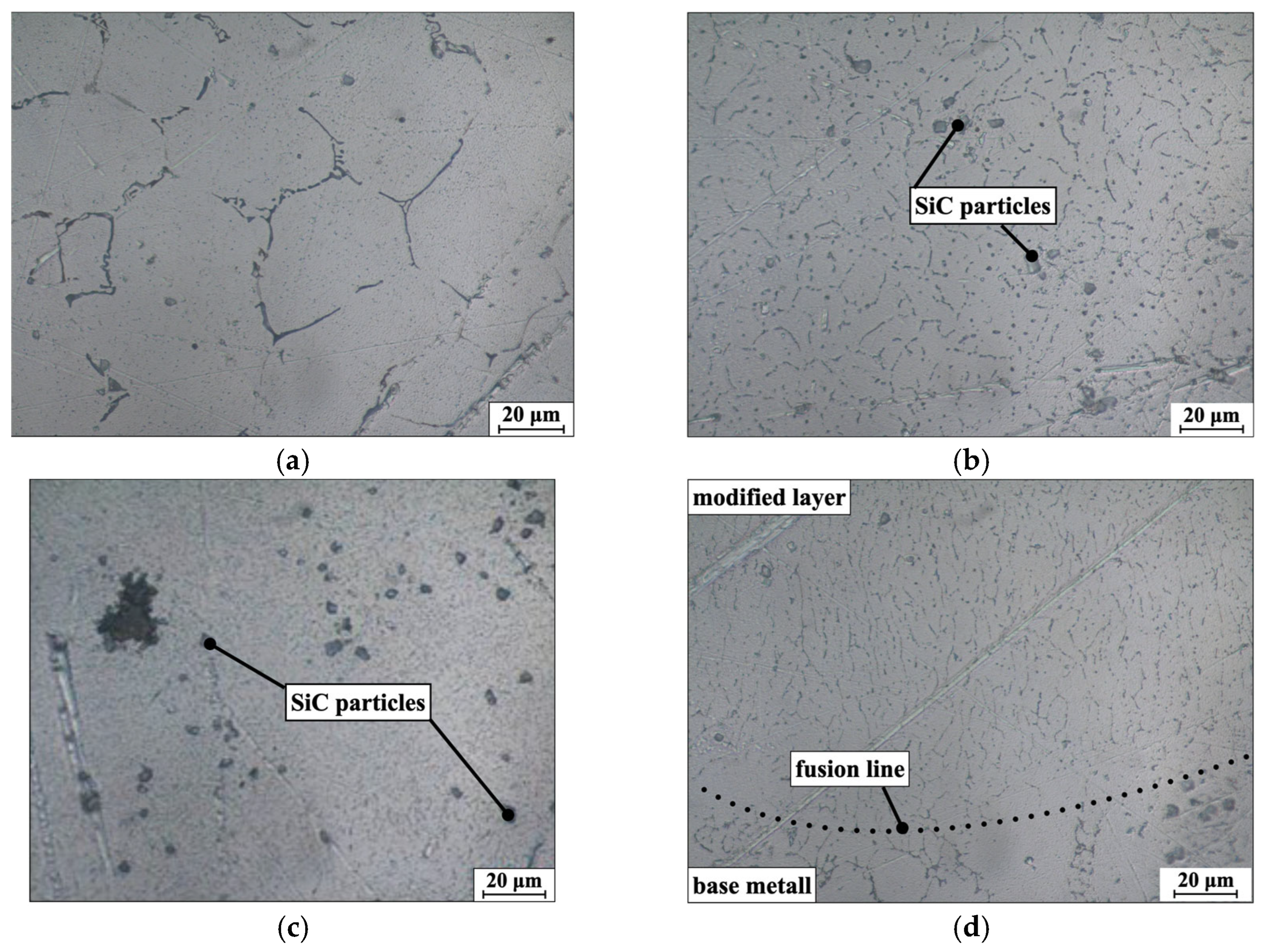
Figure 5 shows the microstructure of the specimens in their initial state and after electron beam treatment. The initial cast structure of the AlMg3 matrix alloy consists of light, cellular-dendritic α-aluminum solid solution crystals, with an average size of 50 μm. Layers of excess phase containing Mg aluminides are present along the boundaries of the α-aluminum solid solution crystals (Figure 5a).
Electron beam treatment in all tested modes leads to the refinement of the initial matrix structure due to high cooling rates. The size of the α-Al solid solution cellular-dendritic crystals decreases to 5–10 μm, and the interlayer thickness does not exceed 2 μm (Figure 5b,c). Reinforcing particles (SiC) remain in the AMC’s microstructure after surface modification. No signs of their degradation into interphase reaction products with the matrix alloy (needle-shaped Al4C3 particles [47]) were detected by optical microscopy. Near the fusion line, it is important to note that the refinement of the modified layer structure is less: the crystals are 12–15 µm in size (Figure 5d). This is due to the partial inheritance of the substrate structure during the epitaxial crystallization process, as well as lesser constitutional supercooling at the beginning of the molten pool crystallization [48].
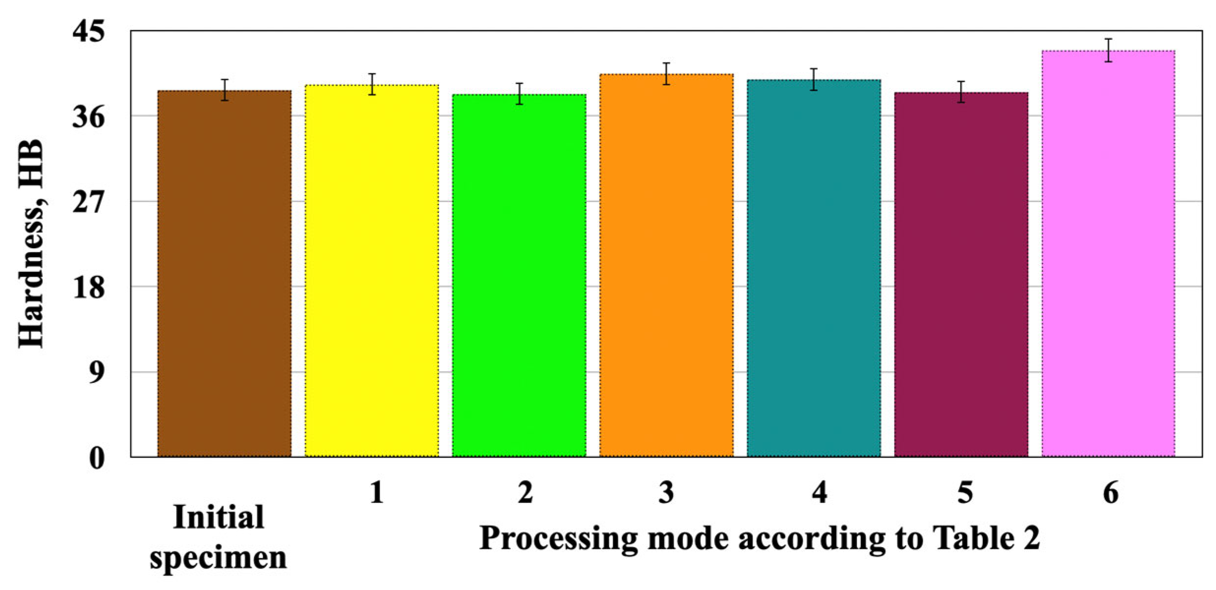
Figure 6 shows the hardness measurement results for the specimens. Surface modification increases hardness values compared to the initial cast state, which has a hardness of 38.7 HB. Specimens processed according to mode 6 in Table 2 have the highest hardness value. The combination of the pulse sweep and the highest processing speed, characteristic of this mode, ensures an increase in the cooling rate of the molten pool. This results in a refined matrix alloy structure with a uniform distribution of reinforcing particles and an 11% increase in surface layer hardness (Figure 5c). The absence or insignificant increase in the surface hardness of specimens processed under other conditions is associated with discontinuities in the form of craters and other imperfections on their surface.
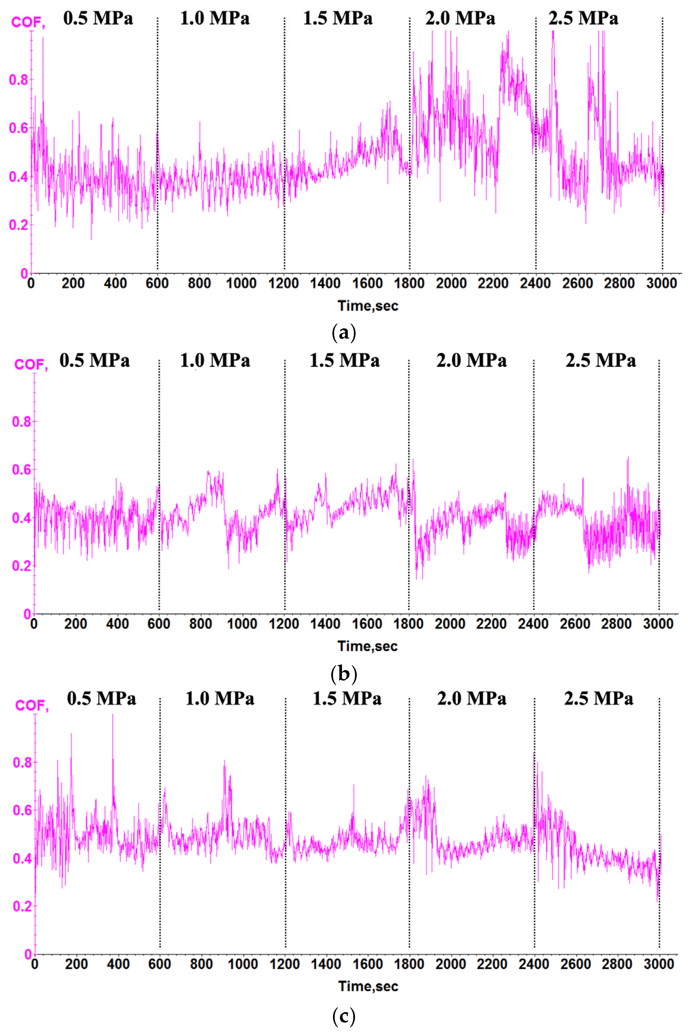
Figure 7 shows typical diagrams of changes in the friction coefficient obtained during testing of specimens under dry sliding friction conditions. Abrupt changes or spikes in the friction coefficient likely result from changes in the friction groove’s shape or the temporary stick/slip occurrence. During stick/slip, the friction surface roughens, causing intermittent motion and fluctuations in the measured coefficient [16,17,49]. This changes the actual contact area, affecting the friction coefficient value. According to the obtained diagrams, the dry sliding friction process of AMCs specimens after electron beam treatment is more stable than the initial cast state, as evidenced by the smaller spread of friction coefficient values. This difference is particularly evident at loads greater than 2.0 MPa.
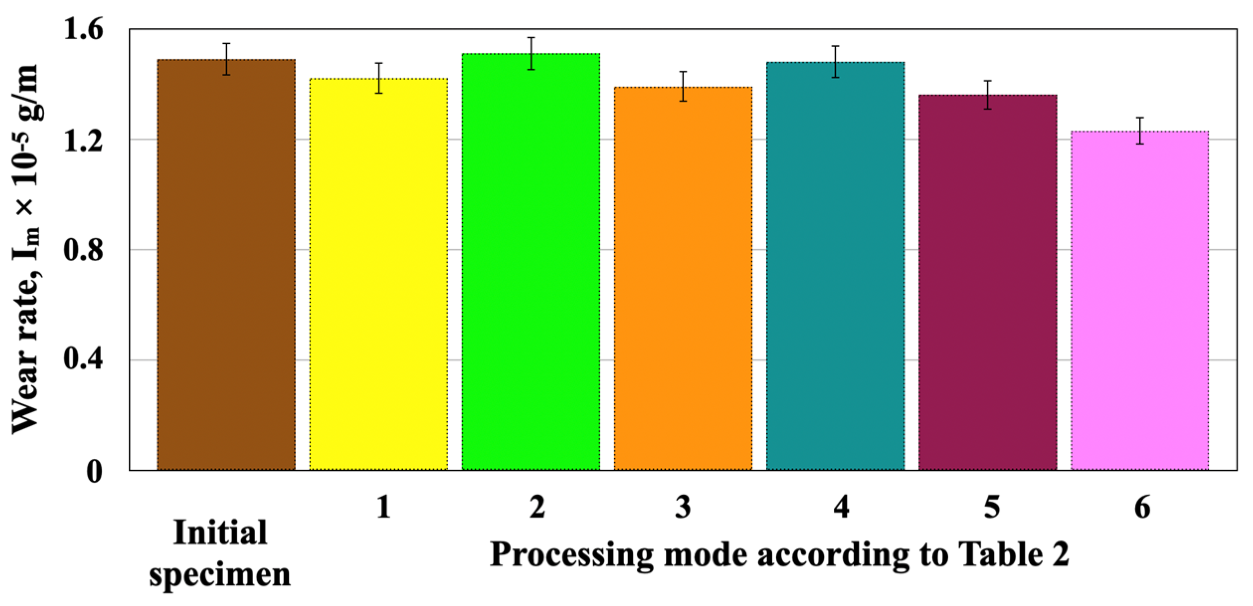
Dry sliding friction and wear tests demonstrate that surface modification significantly improves the tribological properties of the specimens, as shown in Figure 8 and Table 4 and Table 5. The wear rate, which characterizes the wear resistance of the specimens, decreases by 17.5% after the electron beam treatment compared to the initial state (1.23 × 10⁻⁵ g/m versus 1.49 × 10⁻⁵ g/m, Figure 8). This decrease is due to a reduction in the size of the α-Al solid solution areas, while the reinforcing particles remain unchanged. Additionally, an increase in hardness results from local, high-energy exposure to an electron beam. This increase is reflected in the abrasive and adhesive wear mechanisms of the specimens [17,49]. The greatest increase in wear resistance was observed for specimens processed according to mode 6, which is due to the maximum hardness level of the modified surface layer.
The average friction coefficient values of the specimens after electron beam treatment range from 0.317 to 0.503 (Table 4). In terms of magnitude, these values are comparable to or smaller than those of the initial specimens (from 0.383 to 0.647) across the entire triboloading range. The friction coefficient values of all the tested specimens predominantly decrease as the specific load increases, which is characteristic of a stable sliding friction process. At this stage, a transition layer, also known as a “third body”, forms between the rubbing surfaces, protecting the specimen from wear [17]. According to references [17,50,51], the transition layer is a nanostructured, mechanical mixture of the counterbody and the test specimen materials, as well as their oxides. This mixture ensures low friction coefficient values. Furthermore, the greatest effect of surface modification is observed at high specific loads (over 1.5 MPa), where the difference in average friction coefficient values between the initial and modified specimens is 43% (0.371 versus 0.647 for the specimen processed according to mode 5 and the initial specimen, respectively, at a specific load of 2.0 MPa).
The friction process of the specimens after electron beam treatment exhibits greater stability than the initial cast specimens (Table 5). Specimens with a modified surface, in particular, are characterized by relatively low root mean squared error values of the friction coefficient (no more than 0.17), indicating stabilization of the friction process. In contrast, the friction process of the initial AMC specimens exhibits σ values ranging from 0.09 to 0.22. At specific loads greater than 2.0 MPa, the difference between the σ values of the modified specimens and the initial specimen is twice as large in all tested modes (Figure 7, Table 5). This difference is particularly significant for heavily loaded components in critical machines and mechanisms (such as bearings and plain bearing liners in steam and gas turbines, and in small and medium-sized marine diesel engines).

4. Conclusions

This study investigated the possibility of using electron beam treatment of the surface of cast specimens made of composite materials based on an AlMg3 alloy reinforced with 5 wt.% SiC particles. The experimental results show that a maximum modified layer thickness of 1705 µm is allowed by processing modes with a heat input of 240 J/mm. The heat input of the processing mode should not exceed 150 J/mm in order to ensure the formation of a modified layer with a smooth and defect-free surface. At the same heat input values, the electron beam treatment with a straight sweep produces a thicker modified layer than processing with a pulse sweep. After electron beam treatment, the size of the α-Al solid solution cellular-dendritic crystals in the matrix alloy decreased by 5–10 times (from 50 µm to 5–10 µm) due to the high cooling rates. The hardness of the surface layer increased by 11%. Friction and wear tests revealed that AMCs with a modified surface exhibit superior tribological properties (wear rate, average friction coefficient, and friction process stability) compared to the original material. Specifically, the wear rate decreased by 17.5%, the average friction coefficient at a specific load of 2.5 MPa decreased by 32%, and the root mean squared error of the friction coefficient, which characterizes the stability of the friction process, decreased by 50%. Future research will focus on a detailed study of the temperature and time conditions of the electron beam modification process for composite materials. The influence of these conditions on the structural refinement and surface properties of composite materials based on AMg3 alloy with varying reinforcement levels will be examined.

Author Contributions

Conceptualization, R.M., I.K. and E.T.; methodology, P.B., L.K. and A.S.; validation, R.M., P.B. and I.K.; investigation, P.B., L.K., E.T. and A.S.; resources, I.K. and A.S.; data curation, R.M.; writing—original draft preparation, P.B., L.K., E.T. and A.S.; writing—review and editing, S.M., R.M. and I.K.; supervision, R.M. and I.K.; project administration, R.M.; funding acquisition, S.M. All authors have read and agreed to the published version of the manuscript.

Funding

This research was supported by the State Task no. 075-00319-25-00.

Data Availability Statement

The original contributions presented in this study are included in the article. Further inquiries can be directed to the corresponding author.

Conflicts of Interest

The authors declare no conflicts of interest.

References

  1. Xu, F.; Ding, N.; Li, N.; Liu, L.; Hou, N.; Xu, N.; Guo, W.; Tian, L.; Xu, H.; Wu, C.; et al. A review of bearing failure Modes, mechanisms and causes. Eng. Fail. Anal. 2023, 152, 107518. [Google Scholar] [CrossRef] [Scilit]
  2. Iwata, T.; Fukuda, M.; Oikawa, M.; Kano, M.; Mihara, Y. Acoustic emission analysis of seizure transition process between steel journals and aluminum alloy plain bearings. Tribol. Int. 2025, 202, 110324. [Google Scholar] [CrossRef] [Scilit]
  3. Podrabinnik, P.; Mironov, A.; Gersman, I. The influence of secondary structures on wear resistance of experimental aluminum alloys for monometallic slide bearings. Mater. Today Proc. 2019, 11, 175–180. [Google Scholar] [CrossRef] [Scilit]
  4. Wang, Z.-M.; Yang, Q.; Sun, Z.-P.; Zhang, B.-R.; Zhao, W.; Rao, W.-F. The effects of Bi and Pb on the soft phase in Al82Sn15Si2.2Cu0.8 sliding bearing alloy. Mater. Charact. 2020, 170, 110684. [Google Scholar] [CrossRef] [Scilit]
  5. Liu, W.; Wei, L.; Zhang, Y.; Chen, S.; Zhao, G.; Gao, G.; Wang, H. Investigation of tribological behavior and failure mechanisms of PEEK-based composites, babbitt alloy, and CuSn10Pb10 bimetal for wind turbine main shaft sliding bearings under simulated operational conditions. Tribol. Int. 2025, 204, 110522. [Google Scholar] [CrossRef] [Scilit]
  6. Luo, K.; Xiong, H.; Zhang, Y.; Gu, H.; Li, Z.; Kong, C.; Yu, H. AA1050 metal matrix composites reinforced by high-entropy alloy particles via stir casting and subsequent rolling. J. Alloys Compd. 2022, 983, 162370. [Google Scholar] [CrossRef] [Scilit]
  7. Wang, Y.; Monetta, T. Systematic study of preparation technology, microstructure characteristics and mechanical behaviors for SiC particle-reinforced metal matrix composites. J. Mater. Res. Technol. 2023, 25, 7470–7497. [Google Scholar] [CrossRef] [Scilit]
  8. Akbarpour, M.R.; Gazani, F.; Mirabad, H.M.; Khezri, I.; Moeini, A.; Sohrabi, N.; Kim, H.S. Recent advances in processing, and mechanical, thermal and electrical properties of Cu-SiC metal matrix composites prepared by powder metallurgy. Prog. Mater. Sci. 2023, 140, 101191. [Google Scholar] [CrossRef] [Scilit]
  9. Soni, S.K.; Nagarjuna, C.; Mohan, M.; Prakash, V.J.; Dewangan, S.K.; Sharma, S.K.; Thomas, S.B.; Sharma, V.K.; Thomas, B. Recent progress in metal matrix hybrid composites fabricated via liquid and solid-state processing: Fabrication techniques, characteristics and future prospects. J. Alloys Compd. 2025, 1032, 181064. [Google Scholar] [CrossRef] [Scilit]
  10. Laghari, R.; Jamil, M.; Laghari, A.; Khan, A.M. Material characteristics and machinability of metal matrix composite materials: A critical review on recent advances and future perspectives. Measurement 2025, 242, 115839. [Google Scholar] [CrossRef] [Scilit]
  11. Khalid, M.Y.; Umer, R.; Khan, K.A. Review of recent trends and developments in aluminium 7075 alloy and its metal matrix composites (MMCs) for aircraft applications. Results Eng. 2023, 20, 101372. [Google Scholar] [CrossRef] [Scilit]
  12. Idusuyi, N.; Olayinka, J.I. Dry sliding wear characteristics of aluminium metal matrix composites: A brief overview. J. Mater. Res. Technol. 2019, 8, 3338–3346. [Google Scholar] [CrossRef] [Scilit]
  13. Samal, P.; Vundavilli, P.R.; Meher, A.; Mahapatra, M.M. Recent progress in aluminum metal matrix composites: A review on processing, mechanical and wear properties. J. Manuf. Process. 2020, 59, 131–152. [Google Scholar] [CrossRef] [Scilit]
  14. Lu, T.; He, T.; Li, Z.; Chen, H.; Han, X.; Fu, Z.; Chen, W. Microstructure, mechanical properties and machinability of particulate reinforced Al matrix composites: A comparative study between SiC particles and high-entropy alloy particles. J. Mater. Res. Technol. 2020, 9, 13646–13660. [Google Scholar] [CrossRef] [Scilit]
  15. Wasik, A.; Leszczynska-Madej, B.; Madej, M. Sustainability in the manufacturing of eco-friendly aluminum matrix composite materials. Sustainability 2024, 16, 903. [Google Scholar] [CrossRef] [Scilit]
  16. Lin, F.; Ren, M.; Wu, H.; Jui, L.; Zhu, L.; Yang, M.; Xu, J.; Chen, Z.; Jiang, Z. Effects of TiB2 content on microstructural evolution, microhardness and tribological behaviours of Al matrix composites reinforced with TiB2 particles. Ceram. Int. 2024, 50, 11049–11059. [Google Scholar] [CrossRef] [Scilit]
  17. Du, A.; Lattanzi, L.; Jarfors, A.E.W.; Zheng, J.; Wang, K.; Yu, G. Role of matrix alloy, reinforcement size and fraction in the sliding wear behaviour of Al-SiCp MMCs against brake pad material. Wear 2023, 530–531, 204969. [Google Scholar] [CrossRef] [Scilit]
  18. Gill, R.S.; Samra, P.S.; Kumar, A. Effect of different types of reinforcement on tribological properties of aluminium metal matrix composites (MMCs)—A review of recent studies. Mater. Today Proc. 2022, 56, 3094–3101. [Google Scholar] [CrossRef] [Scilit]
  19. Nithesh, K.; Gowrishankar, M.C.; Nayak, R.; Sharma, S. Effect of light weight reinforcement and heat treatment process parameters on morphological and wear aspects of hypoeutectic Al-Si based composites—A critical review. J. Mater. Res. Technol. 2021, 35, 4272–4292. [Google Scholar] [CrossRef] [Scilit]
  20. Mikheev, R.S.; Kalashnikov, I.E. Aluminium matrix hybrid composite materials reinforced by carbides and intermetallics. E3S Web Conf. 2023, 376, 01011. [Google Scholar] [CrossRef] [Scilit]
  21. Ayvaz, S.I.; Arslan, D.; Ayvaz, M. Investigation of mechanical and tribological behavior of SiC and B4C reinforced Al-Zn-Mg-Si-Cu alloy matrix surface composites fabricated via friction stir processing. Mater. Today Proc. 2022, 31, 103419. [Google Scholar] [CrossRef] [Scilit]
  22. Muzeer, S.; Sivaganesan, D.S. Tribological behaviour of aluminium based hybrid metal matrix composites (Al6061/B4C/ZrO2/SiC). Mater. Today Proc. 2022, 56, 507–513. [Google Scholar] [CrossRef] [Scilit]
  23. Pole, M.; Mukhopadhyay, S.; Kastamo, S.; Loukus, A.; Choi, J.P.; Olszta, M.; Herling, D.R.; Grant, G.J.; Devaraj, A.; Efe, M. Tribological behavior of hybrid Aluminum-TiB2 metal matrix composites for brake rotor applications. Wear 2025, 562–563, 205639. [Google Scholar] [CrossRef] [Scilit]
  24. Parikh, V.K.; Patel, V.; Pandya, D.P.; Andersson, J. Current status on manufacturing routes to produce metal matrix composites: State-of-the-art. Heliyon 2023, 9, e13558. [Google Scholar] [CrossRef] [Scilit]
  25. Bhowmik, A.; Kumar, R.; Beemkumar, N.; Kumar, A.V.; Singh, G.; Kulshreshta, A.; Singh Mann, V.; Johnson Santhosh, A. Casting of particle reinforced metal matrix composite by liquid state fabrication method: A review. Results Eng. 2024, 24, 103152. [Google Scholar] [CrossRef] [Scilit]
  26. Sharma, A.K.; Bhandari, R.; Pinca-Bretotean, C. A systematic overview on fabrication aspects and methods of aluminum metal matrix composites. Mater. Today Proc. 2021, 45, 4133–4138. [Google Scholar] [CrossRef] [Scilit]
  27. Kumar, A.; Vichare, O.; Debnath, K.; Paswan, M. Fabrication methods of metal matrix composites (MMCs). Mater. Today Proc. 2021, 46, 6840–6846. [Google Scholar] [CrossRef] [Scilit]
  28. Unlu, B.S. Investigation of tribological and mechanical properties of Al2O3-SiC reinforced Al composites manufactured by casting or P/M method. Mater. Des. 2008, 29, 2002–2008. [Google Scholar] [CrossRef] [Scilit]
  29. Bhat, K.U.; Panemangalore, D.B.; Kuruveri, S.B.; John, M.; Menedez, P.L. Surface modification of 6xxx series aluminum alloys. Coatings 2022, 12, 180. [Google Scholar] [CrossRef] [Scilit]
  30. Bhadauria, N.; Pandey, S.; Pandey, P.M.; Vashishtha, P. A novel technique for surface modification of aluminium alloy using GTAW. J. Braz. Soc. Mech. Sci. 2023, 45, 57. [Google Scholar] [CrossRef] [Scilit]
  31. Konovalov, S.; Zaguliaev, D.; Ivanov, Y.; Gromov, V.; Abaturova, A. Modification of Al-10Si-2Cu alloy surface by intensive pulsed electron beam. J. Mater. Res. Technol. 2020, 9, 5591–5598. [Google Scholar] [CrossRef] [Scilit]
  32. Shi, G.; Yu, X.; Meng, H.; Zhao, F.; Wang, J.; Jiao, J.; Jiang, H. Effect of surface modification on friction characteristics of sliding bearings: A review. Tribol. Int. 2023, 177, 107937. [Google Scholar] [CrossRef] [Scilit]
  33. Hasan, M.Z.; Mohammed, M.A.; Yousif, I.E. Effect of laser surface heat treatment on wear and hardness sesistance of metal matrix composite from (Al-6061 + SiC particles). Mat. Sci. Forum 2021, 1039, 86–95. [Google Scholar] [CrossRef] [Scilit]
  34. Pazhani, A.; Xavior, A.M. Surface modification on aluminum metal matrix composite for high strength application—Current state of art. Mater. Today Proc. 2020, 46, 7130–7134. [Google Scholar] [CrossRef] [Scilit]
  35. Kolev, M.; Dimitrova, R.; Parshorov, S.; Valkov, S.; Lazarova, R.; Petrov, P. Surface modification of an aluminum alloy by electron beam introducing TiCN nanoparticles. J. Phys. Conf. Ser. 2018, 992, 012042. [Google Scholar] [CrossRef] [Scilit]
  36. Valkov, S.; Ormanova, M.; Petrov, P. Electron-beam surface treatment of metals and alloys: Techniques and trends. Metals 2020, 10, 1219. [Google Scholar] [CrossRef] [Scilit]
  37. Yan, P.; Zou, J.; Zhang, C.; Grosdidier, T. Surface modifications of a cold rolled 2024 Al alloy by high current pulsed electron beams. Appl. Surf. Sci. 2020, 504, 144382. [Google Scholar] [CrossRef] [Scilit]
  38. Del Sol, I.; Batista, M.; Mayuet, P.; Banon, F.; Vazquez-Martinez, J.M. Improvement of the tribological behavior of high reinforcement concentration Al–SiC (63%) metal matrix composite through laser surface texturing. J. Mater. Res. Technol. 2024, 28, 2338–2346. [Google Scholar] [CrossRef] [Scilit]
  39. Grabowski, A.; Lisiecki, A.; Dyzia, M.; Labaj, J.; Stano, S. The effect of laser wavelength on surface layer melting of the AlSi/SiC composite. J. Manuf. Process. 2022, 75, 627–636. [Google Scholar] [CrossRef] [Scilit]
  40. Ghost, A.; Pourkhorshid, E.; Rometsch, P.; Chen, X.G. Microstructure, processability, and strength of SiC-reinforced AlSi9Mg composite after laser surface remelting and post-heat treatment. J. Manuf. Mater. Process. 2025, 9, 379. [Google Scholar] [CrossRef] [Scilit]
  41. Mikheev, R.S.; Chernyshova, T.A. Processing of the surface of a silumin plate with a high-energy source. Russ. Metall. (Met.) 2009, 6, 498–504. [Google Scholar] [CrossRef] [Scilit]
  42. Ivanov, Y.F.; Gromov, V.E.; Zagulyaev, D.V.; Konovalov, S.V.; Rubannikova, Y.A. Improvement of functional properties of alloys by electron beam treatment. Steel Transl. 2022, 52, 71–75. [Google Scholar] [CrossRef] [Scilit]
  43. Ivanov, Y.; Zaguliaev, D.; Konovalov, S.; Klopotov, A.; Ustinov, A.; Yakupov, D. Surface modification of sub-eutectic silumin by a pulsed electron beam. Surf. Interfaces 2022, 29, 101810. [Google Scholar] [CrossRef] [Scilit]
  44. Bryukhovetsky, V.V.; Klepilov, V.F.; Lytvynenko, V.V.; Myla, D.E.; Lonin, Y.F.; Ponomarev, A.G. The structural phase state and strength properties of the surface layer of AA6111-T4 aluminum alloy irradiated by the high-current electron beam. Nucl. Instrum. Methods Phys. Res. B 2022, 519, 1–8. [Google Scholar] [CrossRef] [Scilit]
  45. Chernyshova, T.A.; Mikheev, R.S.; Kalashnikov, I.E.; Akimov, I.V.; Kharlamov, E.I. Development and testing of Al-SiC and Al-TiC composite materials for application in friction units of oil-production equipment. Inorg. Mater. Appl. Res. 2011, 2, 322–329. [Google Scholar] [CrossRef] [Scilit]
  46. Bykov, P.A.; Kalashnikov, I.E.; Kobeleva, L.I.; Katin, I.V.; Mikheev, R.S. Wear modes in testing the antifriction layer of babbit B83. Lett. Mater. 2022, 12, 219–224. [Google Scholar] [CrossRef] [Scilit]
  47. Chen, G.; Yin, Q.; Cao, J.; Zhang, G.; Zhen, G.; Zhang, B. Electron beam surface heating-diffusion bonding: An effective joining method for aluminum alloy metal-matrix composite with high SiC volume. J. Mater. Sci. Technol. 2021, 88, 109–118. [Google Scholar] [CrossRef] [Scilit]
  48. Liu, Q.; Jin, Y.; Bian, Q.; Yang, H.; Zhang, T.; Li, J.; Wang, J. Influence of the solidification rate on the microstructure and mechanical properties of rapidly solidified Al-Mg-Si alloy. J. Mater. Res. Technol. 2025, 39, 692–702. [Google Scholar] [CrossRef] [Scilit]
  49. Bykov, P.A.; Kalashnikov, I.E.; Kobeleva, L.I.; Katin, I.V.; Mikheev, R.S. Mapping wear modes of composite materials with intermetallic reinforcing based on antifrictional alloy of system Al-Sn-Cu. Lett. Mater. 2021, 11, 181–186. [Google Scholar] [CrossRef] [Scilit]
  50. Song, P.; Yang, Z.; Zang, J.; Sun, M.; Li, P.; Li, P. Effects of thermal cycling treatment on load bearing and friction behavior of SiCp/A356 composites. Eng. Fail. Anal. 2024, 156, 107828. [Google Scholar] [CrossRef] [Scilit]
  51. Singh, H.; Singh, K.; Vardhan, S.; Mohan, S.; Singh, G. A comprehension review of dry sliding wear on aluminum matrix composites. Mater. Today Proc. 2022, 58, 886–894. [Google Scholar] [CrossRef] [Scilit]
Figure 1. Schemes of surface modification with straight (a) and pulse (b) sweep. The numbers indicate: 1—electron beam; 2—molten pool.
Lubricants 14 00050 g001
Figure 2. Appearance (a) and scheme of dry sliding friction and wear tests (b), where p is the specific load, n is the rotational speed of the bushing.
Lubricants 14 00050 g002
Figure 3. Macrostructure at the start and end of a layer processed according to the modes: (a)—1, (b)—2, (c)—3, (d)—4, (e)—5, and (f)—6. The mode numbers correspond to Table 2.
Lubricants 14 00050 g003
Figure 4. The surface of the specimens in the initial state (a) and processed according to the modes: (b)—1, (c)—3, and (d)—6. Mode numbers correspond to Table 2.
Lubricants 14 00050 g004
Figure 5. Microstructure of the specimens in the initial cast state (a) and after electron beam treatment: upper part of the modified layer (b,c), and area near the fusion line (d). Modes: (b)—3 and (c), (d)—6 are according to Table 2.
Lubricants 14 00050 g005
Figure 6. Hardness of AMCs specimens in the initial state and after electron beam treatment.
Lubricants 14 00050 g006
Figure 7. Diagrams showing changes in friction coefficient for AMC specimens in the initial cast state (a) and after electron beam treatment according to modes: (b)—5 and (c)—6. Mode numbers correspond to Table 2.
Lubricants 14 00050 g007
Figure 8. Wear rate of specimens in the initial state and after electron beam surface treatment.
Lubricants 14 00050 g008
Table 1. Chemical composition of AlMg3 alloy, wt.%.
AlMgMnSiFeCuZnTi
Bal.3.50.40.550.350.050.10.05
Table 2. The electron beam treatment parameters.
Mode NumberE-Gun Speed V, mm/minBeam Current I, mASweep Frequency υ, HzType of SweepHeat Input Q, J/mm
112064direct180
2240108150
31503pulsed240
46002512150
5600300 *
612004024120
* Processing is carried out in two passes.
Table 3. Modified layer thickness depending on electron beam treatment parameters.
Mode NumberThickness of the Modified Layer, µm
Start of the LayerEnd of the Layer
1210422
2275476
31841705
474178
5223611
6127274
Table 4. Average friction coefficient (f) of specimens in the initial state and after electron beam treatment, depending on the processing mode.
Mode NumberAverage Friction Coefficient, f, Depending on Specific Load, p, MPa
0.51.01.52.02.5
initial specimen0.401 ± 0.0010.383 ± 0.0010.461 ± 0.0010.647 ± 0.0020.497 ± 0.002
10.368 ± 0.0010.360 ± 0.0010.403 ± 0.0010.404 ± 0.0010.399 ± 0.001
20.464 ± 0.0010.482 ± 0.0010.426 ± 0.0010.468 ± 0.0010.458 ± 0.002
30.405 ± 0.0010.376 ± 0.0010.317 ± 0.0010.503 ± 0.0010.397 ± 0.001
40.467 ± 0.0010.422 ± 0.0010.415 ± 0.0010.423 ± 0.0010.431 ± 0.001
50.398 ± 0.0010.417 ± 0.0010.449 ± 0.0010.371 ± 0.0010.386 ± 0.001
60.497 ± 0.0010.451 ± 0.0010.431 ± 0.0010.455 ± 0.0010.405 ± 0.001
Table 5. Root mean squared error of the friction coefficient (σ) of specimens in the initial state and after electron beam treatment, depending on the processing mode.
Mode NumberRoot Mean Squared Error of the Friction Coefficient, σ, Depending on Specific Load, p, MPa
0.51.01.52.02.5
initial specimen0.160.090.090.210.22
10.120.090.080.080.11
20.140.100.060.070.10
30.140.130.100.120.11
40.170.140.120.060.13
50.100.090.070.100.14
60.120.090.070.100.11
Disclaimer/Publisher’s Note: The statements, opinions and data contained in all publications are solely those of the individual author(s) and contributor(s) and not of MDPI and/or the editor(s). MDPI and/or the editor(s) disclaim responsibility for any injury to people or property resulting from any ideas, methods, instructions or products referred to in the content.