Abstract
This study aims to evaluate the tribological performance of commercial PVD coatings in alleviating material transfer under unlubricated contact in the hot forming of aluminum alloy. The commercial PVD coatings included AlCrN, TiAlN, and Arc-DLC coatings, deposited on the forming tool surface. The warm and hot upsetting sliding test (WHUST) was used as a friction test in this study to reproduce the severe contact conditions from the hot forming process of AA6082-T6 aluminum alloy. The WHUST was performed at 300 °C, 400 °C, and 500 °C to investigate the effect of temperature on the tribological performance of each coating. The results found that the AlCrN and TiAlN coatings exhibited similar performance. They dominated the initial aluminum transfer by adhesive bonding. In contrast, the Arc-DLC coating mainly caused the initial aluminum transfer by mechanical plowing due to its lower chemical affinity to the aluminum alloy. In addition, the tribological performance of each coating highly depended on the temperature. Higher temperatures resulted in both stronger intermetallic bonding at the interface and lower yield strength of the aluminum alloy. These behaviors led to the variations in the coefficient of friction, the 3D topography and the SEM morphology along the wear track of the specimen, and the thickness of the adhered aluminum layer on the coating surface. In comparison, the Arc-DLC coating provided better tribological performance in mitigating the aluminum transfer than the others.
1. Introduction
In recent years, demand for light metals in transportation applications has continuously increased to improve fuel efficiency and reduce CO2 emissions due to the global sustainability goals [1,2]. Aluminum alloys are particularly popular for producing several automotive and aircraft components because of their high strength-to-weight ratio, excellent corrosion resistance, and recyclability [3]. Metal forming processes are widely used to manufacture such components since they can offer high material utilization and high productivity [4]. However, during the forming process, the strong chemical tendency of aluminum alloys to bond with tool steels can lead to the material transfer issue. This issue deteriorates the surface quality of the product and shortens the service life of the forming tool [5].
Over the last decade, many studies have been conducted to understand the mechanisms of aluminum transfer at the tool-workpiece interface to solve the issue [6,7,8,9]. For example, J. Heinrichs et al. [8] explained that aluminum transfer on the forming tool surface occurs in several stages. Nonetheless, the primary stage is the most critical because it significantly affects the progression of the later stages. In the primary stage, the aluminum transfer can be caused by mechanical scraping and/or chemical bonding. For mechanical scraping, the surface topography of the forming tool plays a crucial role. Thus, improving the roughness of the forming tool surface can be a solution to mitigate the aluminum transfer [10,11]. On the other hand, for chemical bonding, the bonding strength at the interface is a key factor. Therefore, to alleviate the aluminum transfer due to the chemical bonding, the most common approach is to prevent the aluminum alloy from coming into direct contact with the tool steel by using lubricants and/or applying thin film coatings on the forming tool surface [12].
In cold forming of aluminum alloys, a soap-based lubricant deposited on the workpiece surface can deal with the material transfer issue effectively [13]. In addition, A. Dubois et al. [14] found that molybdenum disulfide (MoS2) can protect the workpiece surface and delay the onset of aluminum transfer. Nevertheless, the future trend nowadays is moving toward green lubricant or lubricant-free forming concepts [15,16]. Therefore, the thin film coating is necessary to achieve the concept. From the literature review, numerous articles similarly reported that DLC coatings are the best candidate applied in aluminum forming processes [17,18]. However, the DLC coating needs to be polished very well in order to use it under unlubricated contact [6]. This is confirmed by T. Abraham et al. [19] which have successfully conducted the lubricant-free forming concept in the deep drawing process of a rectangular cup by using the C:H DLC coating with a very smooth surface.
In hot forming of aluminum alloys, A. Ghiotti et al. [20] found that graphite-based lubricant can prevent the material transfer issue. Graphite additive results in the best tribological performance compared to other additives [21]. Furthermore, L. Schell et al. [22] proved that mixing different lubricant classes can improve tribological performance. On the other hand, for the thin film coating, several articles dissimilarly reported. For instance, M. Kalin et al. [23] found that the TiAlN coating leads to less aluminum transfer at 300 °C, whereas the CrN coating is better at higher temperatures: 400 °C and 500 °C. In contrast, T. Funazuka et al. [24] discovered that AlCrN coating causes low friction in their hot extrusion process of aluminum alloy. Due to low friction at the interface, the tearing defects on the workpiece surface are suppressed. Moreover, N. Rigas et al. [25] reported that lubricant-free forming can be achieved by using the ta-C DLC coating. From those studies, an effective coating deposited on the forming tool surface remains an open question in the hot forming of aluminum alloys.
The aim of this study is to evaluate the tribological performance of commercial PVD coatings under an unlubricated interface in the hot forming of aluminum alloy. The commercial PVD coatings consisted of AlCrN, TiAlN, and Arc-DLC coatings. The warm and hot upsetting sliding test (WHUST) was used as a friction test to reproduce the severe interface conditions associated with the hot forming process of AA6082-T6 aluminum alloy [26]. Furthermore, the WHUST was conducted at three different temperatures between 300 °C and 500 °C to investigate the influence of temperature on the coating performance. The tribological performance in this study involved three aspects: the coefficient of friction (COF), the 3D topography and the SEM morphology along the wear track of the specimen, and the adhered aluminum layer on the coating surface.
2. Experiments
2.1. Warm and Hot Upsetting Sliding Test (WHUST)
In this study, the warm and hot upsetting sliding test (WHUST) was selected as the friction test because the WHUST was specifically designed to simulate the contact conditions in hot metal forming processes: it can reproduce high contact pressure and generate plastic strain along the specimen surface [26]. Moreover, the WHUST can capture the evolution of COF variation over the sliding distance due to its direct measurement method [27]. The evolution of COF is very useful information to assess the coating performance in mitigating the aluminum transfer since the aluminum transfer typically occurs in several stages [8].
The schematic of the WHUST is shown in Figure 1. The workpiece in hot forming processes is represented by the specimen, and the forming tool is simulated by the contact. Regarding the working principle, the WHUST generates plastic strain by sliding the contactor against the specimen. The plastic strain is localized on the specimen surface. It can be controlled by the penetration depth between the contactor and the specimen. The input parameters of this test include materials of the specimen and the contactor, surface characteristics of the specimen and the contactor, lubricants, penetration depth, sliding speed, as well as the temperatures of the specimen and the contactor at the beginning of the test. The WHUST is operated in four steps. Firstly, the specimen and the contactor are heated to the initial testing temperatures. Secondly, the penetration depth is set. Then, the contactor slides against the specimen with a constant penetration depth and a constant sliding speed. During the slide, forces are recorded in both normal and tangential directions. Finally, the specimen and the contactor are cooled down. After the test, the direct output data consists of the normal and the tangential forces, as well as the specimen and the contactor surfaces. They are used to identify the COF and perform surface analyses, such as the surface characteristics, the quantification of transferred aluminum, etc.
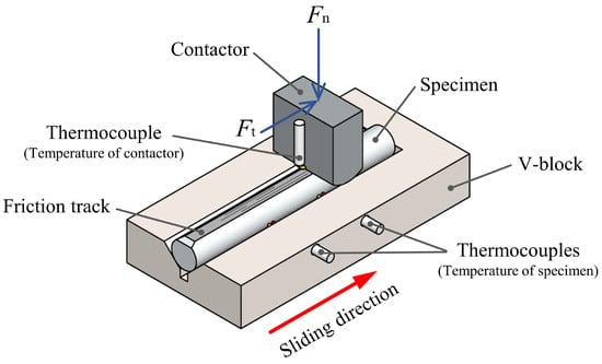
Figure 1.
Schematic of the WHUST.
2.2. Materials
2.2.1. Specimen
In this study, the specimens were fabricated from AA6082-T6 aluminum alloy. This material is commonly used to produce several automotive components in the industry [28]. Its chemical composition is given in Table 1. The specimen was machined to a geometry of Ø5 × 40 mm with a chamfer of 2 mm at one end (Figure 2a). Their arithmetical mean height (Sa) was 0.60 ± 0.25 μm. They were evaluated using a white light interferometer (WLI), from Bruker, France. Furthermore, their surface hardness at room temperature was 135 HV (≈1.3 GPa), measured by the micro-Vickers hardness test, Model: FM-700, with a load of 100 gf.

Table 1.
Chemical composition of AA6082-T6 aluminum alloy (%wt).
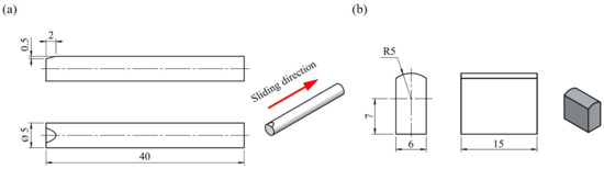
Figure 2.
(a) Specimen geometry, and (b) contactor geometry.
2.2.2. Contactor
The contactors in this study were produced from AISI H13 steel. It is a chromium-based steel typically used for making hot forming tools and dies [29]. Table 2 provides its chemical composition. Their geometry at the interface was a radius of 5 mm (Figure 2b). They were produced through machining, quenching, tempering, and finishing. Before the deposition of the coatings, their Sa was 0.15 ± 0.05 μm. The 3D topography is shown in Figure 3a. Moreover, their surface hardness at room temperature was 48 HRC (≈4.7 GPa). They were investigated by a micro-indentation tester, Bruker, France. After that, the contactor surface was deposited with three different commercial PVD coatings: AlCrN, TiAlN, and Arc-DLC coatings. The reason is that these coatings have great tribological performance and are generally used in many applications. For instance, the AlCrN and TiAlN coatings are applied to cutting tools in machining processes [30,31] and forming tools in hot forming, especially at high temperatures [24,32]. On the other hand, the Arc-DLC coating is used for automotive components [33], medical devices and prosthetics [34], as well as cold forming of aluminum alloys [17,19].
Table 2.
Chemical composition of AISI H13 hot tool steel (%wt).
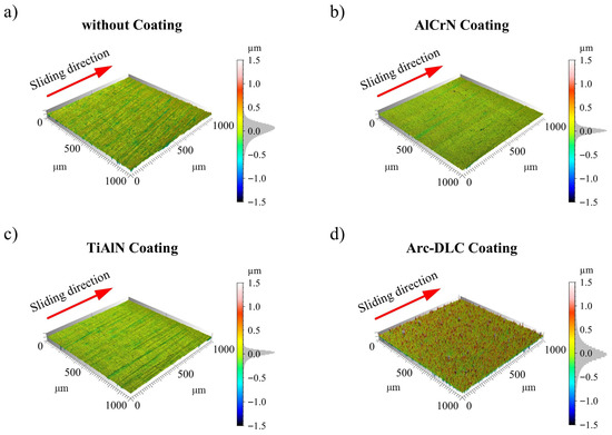
Figure 3.
3D topography: (a) Before depositing the coatings, (b) AlCrN coating, (c) TiAlN coating, and (d) Arc-DLC coating.
Figure 3b–d shows the 3D topography of each coating, and Figure 4 presents the SEM micrographs with the EDS mapping of each coating in a cross-section. In Figure 4, the AlCrN coating was a multi-layer coating, whereas the TiAlN and the Arc-DLC coatings were single-layer coatings. The titanium in the Arc-DLC coatings (Figure 4c) was an interlayer to improve the bonding ability between the DLC layer and the substrate [35]. The thickness and the roughness of the AlCrN and the TiAlN coatings were similar (Table 2). After the deposition of the AlCrN and the TiAlN coatings, the Sa decreased by around 33–47%, respectively. The marks from the machining process disappeared in the case of the AlCrN coating (Figure 3b) but slightly remained in the case of the TiAlN coating (Figure 3c). On the other hand, the thickness of the Arc-DLC coating was thinner than the others. The 3D topography after applying the Arc-DLC coating became more homogeneous since the marks from the machining process disappeared (Figure 3d). However, the Sa increased by approximately 27% due to the formation of droplets in the DLC layer during the depositing process [36,37,38]. The surface hardness of each coating at room temperature, measured by a nano-indentation tester, Model: Bruker Hysitron TI 990 TriboIndenter (Brunker, Palaiseau, France), with a load of 10 mN, is presented in Table 3.
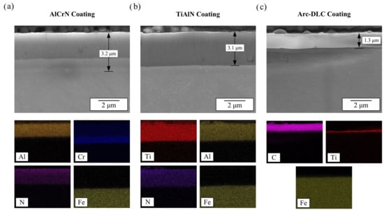
Figure 4.
SEM micrographs and EDS mapping of the coatings in a cross-section: (a) AlCrN coating, (b) TiAlN coating, and (c) Arc-DLC coating.
Table 3.
Characteristics of the coatings.
2.3. Experimental Setup and Procedures
Figure 5 presents the experimental setup. The WHUST was integrated within the Bruker UMT TriboLab platform. The apparatus was installed inside the heating chamber, Model: ROT-1000, to control the temperatures of the specimen and the contactor precisely (Figure 5a). The specimen was located on the V-block fixed on the lower support. On the other side, the contactor was fixed to the upper side by the contactor holder. It was movable along the y-axis to adjust the penetration depth and the x-axis to slide the contactor. The bidirectional load cell, Model: DFH 200-G, was used to record the normal and the tangential forces (Figure 5b). The maximum capacity of the load cell is 2000 N in the x and y axes with a resolution of 0.1 N. Moreover, additional K-type temperature sensors, from TC SAS, Dardilly, France, were used to track the temperatures of the specimen and the contactor. They were directly attached to the specimen and the contactor. Those thermocouples were connected to the data logger that was linked to the Bruker UMT TriboLab platform.
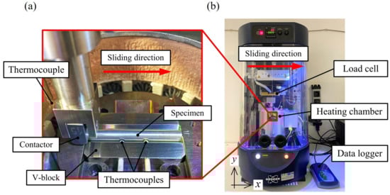
Figure 5.
(a) The WHUST apparatus in the heating chamber and (b) Bruker UMT TriboLab platform.
The experimental procedure of the WHUST in this study involved four steps. Firstly, the specimen and the contactor were heated under atmospheric conditions to the initial testing temperatures and held at those temperatures for 10 min to ensure a uniform temperature before the test began. Secondly, the penetration depth was set. Thirdly, the contactor slid against the specimen. Finally, the specimen and the contactor were cooled down to room temperature in the open air. After the test, Coulomb’s COF as a function of the sliding distance was determined by using Equation (1) [27]. The 3D topography and the morphology along the wear track of the specimen were investigated by the WLI, Model: Bruker Contour GT, by Brunker, Palaiseau, France, and the SEM, Model: JEOL JSM-7100F (Croissy-sur-Seine, France), respectively. On the other side, the adhered aluminum layer on the coating surface was analyzed by the optical microscope with focus variation, Model: Alicona Infinite Focus G5 (Bruker France, Palaiseau, France), and the WLI.
where μ is the Coulomb’s COF, Ft is the tangential force, Fn is the normal force, q is the contact length, p is the penetration depth of the contactor into the specimen, and δ is the height of the elastic recovery.
2.4. Design of Experiments
In this study, Table 4 details the WHUST parameters and contact conditions. The penetration depth of 0.1 mm and the sliding speed of 0.5 mm/s were selected to reproduce the contact conditions from the hot forming process of aluminum alloy [39,40]. The temperature of the contactor (Tc) at the beginning was fixed at 200 °C, while the temperature of the specimen (Ts) at the beginning was varied between 300 °C and 500 °C. They are typical temperatures of the forming tool and the billet in hot forming processes of aluminum alloy [29]. Additionally, all experimental conditions were conducted under unlubricated contact and repeated twice. A new specimen and a new contactor were used for each experiment.
Table 4.
Design of Experiments.
3. Results
The experimental results in this study included the COF, the 3D topography and the SEM morphology along the wear track of the specimen, and the adhered aluminum layer on the coating surface.
3.1. Coefficient of Friction (COF)
The evolution of the COF from three different coatings and temperatures is presented in Figure 6. The solid line exhibits the average of the COF from two experimental repetitions, while the other lines represent the COF from each experiment. Overall, the COF had a similar trend in all cases, separated into transient and stabilized phases. In the transient phase, the COF rapidly climbed up to reach the peak value and then gradually decreased. After that, the COF came to the stabilized phase, where its evolution remained almost constant.
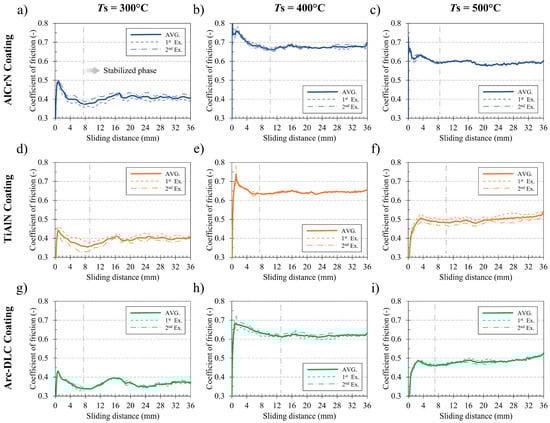
Figure 6.
Evolution of the COF at three different temperatures: (a–c) AlCrN coating, (d–f) TiAlN coating, and (g–i) Arc-DLC coating.
At the beginning of the transient phase, for all temperatures, the AlCrN coating caused the highest peak value of the COF, whereas the Arc-DLC coating resulted in the lowest. Furthermore, the peak value of the COF from all coatings depended on the temperature, similarly. It rose when the temperature increased from 300 °C to 400 °C. Then, it dropped when the temperature increased from 400 °C to 500 °C. After reaching the peak value, the COF gradually decreased until the beginning of the stabilized phase. The sliding distance of the transient phase was between 7 mm and 13 mm.
In the stabilized phase, the trend of the COF from all coatings was also dependent upon the temperature. At 300 °C, the COF in the case of the AlCrN and the TiAlN coatings similarly fluctuated with a small amplitude and short wavelengths (Figure 6a,d). In contrast, in the case of the Arc-DLC coating, the COF fluctuated with a larger amplitude and longer wavelengths (Figure 6g). At 400 °C, the COF from all coatings was more stable when compared to the other temperatures, as illustrated in Figure 6b,e,h. At 500 °C, the COF in the case of the AlCrN coating slightly varied (Figure 6c), whereas the COF from the TiAlN and the Arc-DLC coatings slowly increased as a function of sliding distance (Figure 6f,i).
The average COF during the stabilized phase is compared in Figure 7. The error bars indicate the maximum and the minimum values. Overall, it was found that the average COF from all coatings depended on the temperature. Moreover, the average COF showed a similar trend to the peak value of the COF in the transient phase (Figure 6). The average COF increased with a rise in temperature from 300 °C to 400 °C, and then decreased at 500 °C.
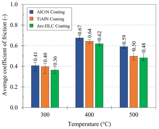
Figure 7.
Average COF in the stabilized period.
In comparison, at 300 °C, the AlCrN and TiAlN coatings caused similar average COF, being 12% and 10% higher than the Arc-DLC coating, respectively. At 400 °C, the highest average COF occurred in the case of the AlCrN coating, whereas the lowest occurred in the case of the Arc-DLC coating. However, the difference in the average COF between all coatings was less than 10%. At 500 °C, the average COF from the TiAlN and Arc-DLC coatings was close together, being 15% and 18% lower than the AlCrN coating, respectively.
3.2. Three-Dimensional Topography and SEM Morphology Along the Wear Track
After the test, the surface along the wear track of the specimens was characterized by the WLI and the SEM. The WLI was used to investigate the 3D topography, and the SEM was used to observe the surface micrograph.
3.2.1. Three-Dimensional Topography Along the Wear Track
The 3D topography was investigated at sliding distances of 1 mm, 4 mm, and every 4 mm until 36 mm. This led to ten measurements for each specimen. The measurement size was 1 × 1 mm at the center of the wear track. The arithmetical mean height (Sa) was applied to evaluate the variation in roughness along the wear track. Figure 8 presents the evolution of the Sa as a function of the sliding distance. It was found that the variation in the Sa could also be classified into transient and stabilized phases. This implies a correlation between the 3D topography and the COF. In addition, Figure 9 and Figure 10 illustrate 3D topography and 2D profiles at the sliding distances of 1 mm and 20 mm, respectively. In the 2D profile diagram, ten profiles were extracted from the perpendicular direction of the sliding. The solid line indicates the average of ten profiles, whereas the shadow represents their individual profiles.
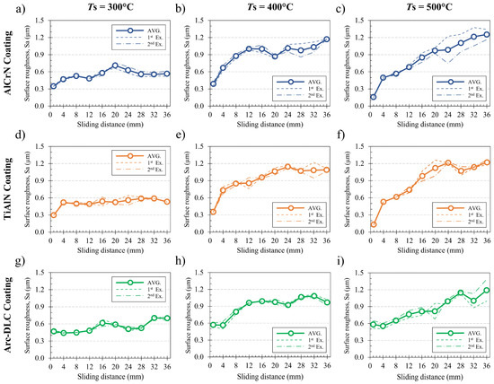
Figure 8.
Evolution of the Sa along the wear track of the specimen at three different temperatures: (a–c) AlCrN coating, (d–f) TiAlN coating, and (g–i) Arc-DLC coating.
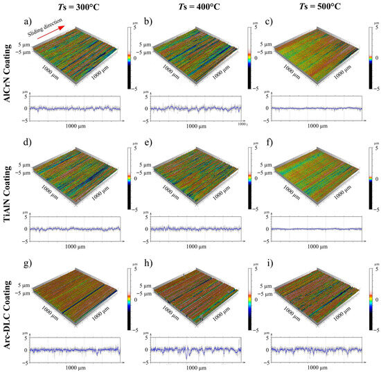
Figure 9.
Three-dimensional topography and 2D profile after 1 mm of sliding distance at three different temperatures: (a–c) AlCrN coating, (d–f) TiAlN coating, and (g–i) Arc-DLC coating.
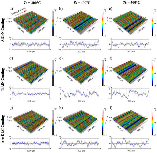
Figure 10.
Three-dimensional topography and 2D profile after 20 mm of sliding distance at three different temperatures: (a–c) AlCrN coating, (d–f) TiAlN coating, and (g–i) Arc-DLC coating.
At the beginning of the transient phase, the Sa from the AlCrN and TiAlN coatings were similar. It ranged between 0.30 μm and 0.40 μm at 300 °C and 400 °C as well as between 0.15 μm and 0.20 μm at 500 °C (Figure 8a–f). Furthermore, the 3D topography at 300 °C and 400 °C contained fine grooves (Figure 9a,b,d,e), while the 3D topography at 500 °C was smoother (Figure 9c,f). On the other hand, the Sa from the Arc-DLC coating ranged between 0.50 μm and 0.60 μm at all temperatures (Figure 8g–i). This was higher than the Sa from the AlCrN and TiAlN coatings. Additionally, the 3D topography in the case of the Arc-DLC coating contained sharper grooves with higher peaks and deeper valleys (Figure 9g–i).
In the transient phase, a rapid change in the Sa was observed in the case of the AlCrN and TiAlN coatings, particularly at sliding distances between 1 mm and 4 mm. The change in the Sa in this phase was in correlation with the variation in the COF. Indeed, the Sa in the case of the AlCrN coating at 400 °C significantly increased from 0.40 μm to 1.00 μm during the first 12 mm of the sliding distance (Figure 8b), and the COF relatively changed during the same sliding distance (Figure 6b). The same phenomenon was found at the other temperatures and with the TiAlN coating. However, a different trend occurred in the case of the Arc-DLC coating. The Sa slightly decreased during the first few millimeters of sliding distance and then increased. Indeed, the Sa in the case of the Arc-DLC coating at 400 °C dropped during the first 4 mm of the sliding distance, and then it rapidly increased from 0.60 μm to 1.00 μm during the next 10 mm of the sliding distance (Figure 8h). The COF significantly changed during the same sliding distance (Figure 6h).
In the stabilized phase, the Sa along the wear track from all coatings had a similar trend (Figure 8). However, the trend of the Sa highly depended on the temperature. The Sa at 300 °C fluctuated around 0.60 μm. In addition, the Sa at 400 °C also fluctuated with a slightly increasing trend between 1.00 μm and 1.20 μm. At 500 °C, the Sa continuously rose from 0.60 μm to 1.20 μm.
Figure 10 shows the 3D topography at the sliding distance of 20 mm, representing the stabilized phase. The 3D topography from all coatings significantly changed when compared to the 3D topography at the beginning (Figure 9). Fine grooves became larger, and peaks as well as valleys became higher. At 300 °C, the 3D topography from the AlCrN and the TiAlN coatings exhibited the same characteristic (Figure 10a,d). Nonetheless, the 3D topography from the Arc-DLC coating was slightly different. Fine grooves remained on the 3D topography (Figure 10g). At higher temperatures, the 3D topography from all coatings was similar. The main difference resulting from the two temperatures was that the grooves at 500 °C were wider than at 400 °C.
3.2.2. SEM Micrograph Along the Wear Track
The SEM was employed to observe the surface along the wear track of the specimen in more detail. Figure 11 and Figure 12 show the surface micrography at sliding distances of 1 mm and 20 mm, respectively. Overall, wear features from the AlCrN and TiAlN coatings were similar, while wear features from the Arc-DLC coating were slightly different, particularly at the beginning.

Figure 11.
Surface micrograph along the wear track of the specimen at the sliding distance of 1 mm at three different temperatures: (a–c) AlCrN coating, (d–f) TiAlN coating, and (g–i) Arc-DLC coating.
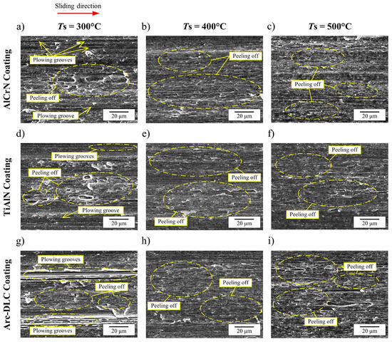
Figure 12.
Surface micrograph along the wear track of the specimen at the sliding distance of 20 mm at three different temperatures: (a–c) AlCrN coating, (d–f) TiAlN coating, and (g–i) Arc-DLC coating.
At the sliding distance of 1 mm, the wear feature, considering the AlCrN and TiAlN coatings at 300 °C and 400 °C, involved both plowing grooves and peeling off. The difference was that the plowing grooves at 300 °C (Figure 11a,d) were more apparent and sharper than at 400 °C (Figure 11b,e). At 500 °C, the surface micrographs contained only peeling off (Figure 11c,f), but the peeling off at this temperature was much finer than in the case of 300 °C and 400 °C. On the other hand, plowing grooves were mainly observed for the Arc-DLC coating at all temperatures. In addition, higher temperatures caused less sharpness of the plowing grooves and slightly more appearance of the peeling off (Figure 11g–i).
For the sliding distance of 20 mm, at 300 °C, the wear feature from all coatings involved both plowing grooves and peeling off. The peeling off was the predominant feature in the case of the AlCrN and TiAlN coatings (Figure 12a,d), and it was larger than the beginning of the sliding distance (Figure 11a,d). The plowing grooves were observed in local areas. On the other hand, the peeling off also became larger for the Arc-DLC coating, but the plowing grooves still appeared at 300 °C (Figure 12g). Additionally, at 400 °C and 500 °C, the surface micrographs from all coatings mainly showed peeling off.
3.3. Adhered Aluminum Layer on the Coating Surface
After the test, the optical microscope with focus variation was used to analyze the adhered aluminum layer on the coating surface. Moreover, the WLI was applied to quantify the thickness of the transferred layer.
Figure 13 shows the adhered aluminum layer on the coating surface at different temperatures. At 300 °C and 400 °C, the morphology of the adhered aluminum layer on all coatings was similar. In contrast, at 500 °C, the transferred layer on the AlCrN and the TiAlN coatings was significantly thicker than the Arc-DLC coating. Furthermore, the transferred layers at 300 °C were more compact when compared to the other higher temperatures. However, it was found that higher temperatures resulted in a larger area of aluminum transfer on the coating surface.
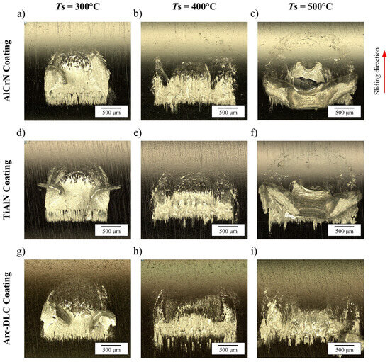
Figure 13.
Adhered aluminum layer on the coating surface at three different temperatures: (a–c) AlCrN coating, (d–f) TiAlN coating, and (g–i) Arc-DLC coating.
The average thickness of the adhered aluminum layer on the coating surface is compared in Figure 14. The error bars indicate the maximum and minimum values of two experimental repetitions. At 300 °C and 400 °C, the adhered aluminum layer on the AlCrN and the TiAlN coatings had similar average thickness. This was approximately 40% and 45% higher than the Arc-DLC coating at 300 °C and 400 °C, respectively. Nevertheless, at 500 °C, the thickness of the adhered aluminum layer on the AlCrN and the TiAlN coatings was significantly high because the transferred layer was not flat. Figure 13c,f shows that the transfer layer was folded when the contactor was removed from the interface at the end of the test. Therefore, the adhered aluminum layer in those cases was much thicker when compared to the Arc-DLC coating at 500 °C. In addition, the thickness of the adhered layer also depended on the temperature. The adhered aluminum layer on all coatings similarly became thinner when the temperature increased from 300 °C to 400 °C, and it became thicker at 500 °C.
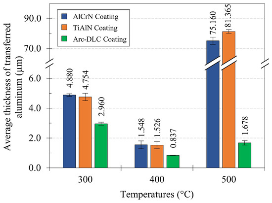
Figure 14.
Average thickness of the adhered aluminum layer on the coating surface.
4. Discussion
According to the experimental results, the tribological performance of the three coatings at different temperatures is discussed based on their initial, transient, and stabilized phases.
4.1. Initial Phase
In the initial phase, the tribosystem was characterized by direct contact between the coating and the aluminum alloy. The results in terms of the Sa at 1 mm (Figure 8a–f), the 3D topography at 1 mm (Figure 9a–f), and the surface micrographs at 1 mm (Figure 11a–f) show that the tribological behaviors induced by the AlCrN and the TiAlN coatings were close for all testing temperatures. For those coatings, the peeling off was mainly found at the beginning of the wear track. This implies a strong adhesion between the coating surface and the aluminum alloy. Thus, the aluminum initially transferred from the specimen to the coating surface due to adhesive bonding. In contrast, in Figure 9g–i and Figure 11g–i, the presence of plowing grooves on the wear track at 1 mm indicated severe scraping of the aluminum alloy by the Arc-DLC coating. Consequently, the aluminum was transferred from the specimen to the surface of the Arc-DLC, resulting from mechanical plowing for all testing temperatures. This is consistent with the study of J.D. Triquenaux et al. [12]. From this perspective, it can be concluded that the AlCrN and TiAlN coatings had a stronger chemical affinity to the aluminum alloy when compared to the Arc-DLC coating. Furthermore, at all temperatures, the COF at the beginning of the tests performed with the AlCrN coating was higher than the TiAlN coating (Figure 6a–f), although the initial surface of the AlCrN coating was smoother than the TiAlN coating (Table 2). Therefore, it indicates that the AlCrN coatings had a stronger adhesion to the aluminum alloy than the TiAlN coating. This finding is also consistent with the study of J. Pujante et al. [42].
From the experimental results, the temperature significantly influenced the tribological performance of all coatings in the initial phase. The peak value of the COF from all coatings increased when the temperature was changed from 300 °C to 400 °C (Figure 6). This is notable because intermetallic bonding between the coating surface and the aluminum alloy became stronger at higher temperatures [23,43]. However, the peak value of the COF decreased at 500 °C. The reason is that the mechanical properties of the aluminum alloy significantly dropped at this temperature due to the thermal softening [23], even though the intermetallic bonding at the interface became stronger.
In addition, the Sa at the beginning in the case of the AlCrN and TiAlN coatings also depended on the temperature. It was found that the Sa at 500 °C was lower than at 300 °C and 400 °C (Figure 8a–f). This is because stronger intermetallic bonding at higher temperatures resulted in different wear patterns on the wear track. At 300 °C, the peeling off was mainly found, while the plowing grooves were also observed in local areas (Figure 11a,d). At 400 °C, the plowing grooves rarely appeared (Figure 11b,e). At 500 °C, the peeling off was only found (Figure 11c,f). On the other hand, the Sa at the beginning in the case of Arc-DLC coating was almost the same value at all temperatures (Figure 8g–i). This is because the wear patterns in the initial phase were mainly driven by the plowing grooves, which were obviously independent of the temperature (Figure 11g–i). Those grooves were directly linked to the initial surface of the Arc-DLC coating.
4.2. Transient Phase
In the transient phase, the COF from all experimental conditions gradually decreased from its peak value to its minimum (Figure 6). During the same period, the Sa along the wear track of the specimen significantly increased (Figure 8). Those behaviors resulted from the transition of the tribosystem from the coating-aluminum alloy contact to the transferred layer-aluminum alloy contact [44]. This caused a change in the mechanisms of aluminum transfer at the interface, leading to different requirements for the sliding force at the interface [45].
The different trend of the Sa between 1 mm and 4 mm was found (Figure 8). In the case of the AlCrN and the TiAlN coatings, the Sa similarly rose during the whole transient phase. In contrast, the Sa in the case of the Arc-DLC coatings slightly decreased and then increased until the beginning of the stabilized phase. Those different phenomena came from dissimilar mechanisms of aluminum transfer from the specimen to the coating surface. For the AlCrN and TiAlN coatings, an increase in the Sa was caused by two reasons. The first reason is that the coating surface became rougher after the adhered aluminum layer stuck on its surface. The other reason is the transition from the coating-aluminum alloy contact to the transferred layer-aluminum alloy contact. This enhanced the chemical affinity of the surfaces and consequently increased the amount of aluminum transfer. Moreover, for the same reason, higher temperatures caused a more significant increase in the Sa in the case of the AlCrN and the TiAlN coatings. On the other hand, for the Arc-DLC coating, the Sa slightly decreased since the initially adhered aluminum layer reduced the sharpness of the coating surface. However, the Sa later increased because the transfer mechanism changed from mechanical plowing to adhesive bonding, similar to the other coatings. Additionally, in this case, the temperature had less effect on the variation in the Sa. This is because the mechanical plowing insignificantly depended on the temperature [7].
4.3. Stabilized Phase
In the stabilized phase, the evolution of the COF and the Sa showed similar trends between each coating at all temperatures (Figure 6 and Figure 8). Nevertheless, the average COF of each coating was slightly different, approximately 2–18%. The slight difference in the average COF came from the adhered aluminum layer covering almost the whole coating surface in contact (Figure 13). This led to the COF being mainly driven by the sliding contact between the transferred layer and the aluminum alloy. Therefore, the coating properties insignificantly influenced the COF [44,46]. Furthermore, the observed peeling along the wear track suggested that aluminum transfer during this phase occurred predominantly through adhesive bonding (Figure 12).
In comparison, the Arc-DLC coating resulted in the lowest average COF for all temperatures (Figure 7). Moreover, the average COF from the uncoated AISI H13 hot tool steel against AA6082-T6 aluminum alloy at 400 °C was 0.69 [27]. From this point, it can be confirmed that all coatings in this study could provide better tribological performance in terms of the COF than the uncoated H13 hot tool steel.
The fluctuation of the COF at 300 °C was found in the case of all coatings (Figure 6a,d,g). It resulted from the removal of the adhered aluminum layer from the coating surface when the transferred layer reached the critical thickness [23]. At higher temperatures, the fluctuation of the COF became less due to stronger adhesive bonding. This led to the transfer layer firmly attached to the coating surface. In addition, the COF from all coatings at 400 °C was almost constant (Figure 6b,e,h). This is because of the balance between the aluminum transfer and the removal of the transferred layer. At 500 °C, the COF slightly increased (Figure 6c,f,i). This came from the accumulation of the adhered aluminum layer without any removals as a result of very strong adhesive bonding. In comparison, in Figure 7, the average COF from all coatings rose with an increase in the temperature from 300 °C to 400 °C due to stronger adhesive bonding at the interface. Following that, the average COF dropped at 500 °C due to the significant decrease in the yield strength of the aluminum alloy. The same behavior was found in previous studies [47].
The temperature also significantly affected the adhered aluminum layer on the coating surface, particularly its thickness (Figure 14). It was found that the transferred layer at 300 °C was thicker than at 400 °C. This can be attributed to the higher mechanical strength of the aluminum alloy at lower temperatures, which made it more difficult to distribute the transferred layer smoothly on the coating surface [48]. On the other hand, the transferred layer at 500 °C was thicker than at 400 °C. This is because the higher temperature resulted in stronger adhesive bonding at the interface. Thus, this caused the accumulation of the transferred layer with less removals.
Furthermore, differences in the size of aluminum transferred onto the coating surface were observed at various temperatures (Figure 13). This phenomenon was caused by two reasons. The first reason is the different sizes of the pile-up material in front of the contactor at each temperature. The other reason is that the thermal softening of the aluminum alloy led to different normal forces during the slide of the contactor against the specimen, causing dissimilar elastic deflection of the machine structure and apparatus.
5. Conclusions
In this study, the tribological performance of AlCrN, TiAlN, and Arc-DLC coatings was evaluated under unlubricated contact in the hot forming of AA6082-T6 aluminum alloy. The WHUST was performed at three different temperatures: 300 °C, 400 °C, and 500 °C, with the relative sliding velocity of 0.5 mm/s. The major findings are concluded as follows:
- The adhered aluminum layer on the coating surface was found for all experimental conditions, whatever coatings and temperatures. The aluminum transfer took place in transient and stabilized phases. The transient phase was identified by the unstable COF and the pronounced increase in the Sa along the wear track of the specimen, while the stabilized phase was characterized by the rather stable COF.
- The AlCrN and TiAlN coatings demonstrated similar tribological performance. The initial aluminum transfer on those coatings was mainly caused by adhesive bonding. However, the AlCrN coating had a stronger chemical affinity to the aluminum alloy than the TiAlN coating since the AlCrN coating caused a higher COF in both transient and stabilized phases, even though the initial surface of the AlCrN coating was smoother.
- Mechanical plowing induced by droplets on the Arc-DLC coating dominated the initial aluminum transfer to the surface coating. Those droplets led to the Sa of the Arc-DLC coatings being higher than the AlCrN and the TiAlN coatings, approximately twice. Nonetheless, the Arc-DLC coating resulted in the lowest COF in both transient and stabilized phases. This indicates that the Arc-DLC coating had a weaker chemical affinity to the aluminum alloy than the other coatings.
- In the stabilized phase, the COF and the Sa along the wear track were slightly different between each coating. This is because the sliding contact was mainly driven by the transferred layer against the aluminum alloy. According to the presence of peeling off along the wear track in this phase, it implied that adhesive bonding dominated the aluminum transfer.
- The temperature also significantly influenced the tribological performance of all coatings. The COF rose with an increase in the temperature from 300 °C to 400 °C due to stronger adhesive bonding at the interface. Nevertheless, the COF dropped at 500 °C because of a significant decrease in the mechanical properties of the aluminum alloy.
- The transferred layer on all coatings at 300 °C was thicker than at 400 °C since the greater mechanical properties of the aluminum alloy at the lower testing temperature made it harder to distribute the adhered aluminum layer on the coating surface smoothly. In contrast, the adhered aluminum layer at 500 °C was thicker than at 400 °C. This resulted from a strong adhesive bonding at 500 °C, affecting less removal of the transferred aluminum.
- According to the experimental results in this study, the Arc-DLC coating could provide better tribological performance to alleviate the aluminum transfer than the AlCrN and the TiAlN coatings. This is because the Arc-DLC coating resulted in the lowest COF and the thinnest transferred layer when compared to the others.
Author Contributions
Conceptualization: P.S., A.D. and L.D.; methodology: P.S., A.D., P.M. and L.D.; software: P.S., A.D. and P.M.; validation: P.M., T.F., K.D. and L.D.; investigation, P.S., T.F. and L.D.; resources: A.D., P.M., T.F., K.D. and L.D.; data curation: P.S.; writing—original draft preparation: P.S.; writing—review and editing: A.D., P.M., T.F., K.D. and L.D.; visualization: P.S.; supervision: P.M., T.F., K.D. and L.D.; project administration: A.D.; funding acquisition: K.D.; All authors have read and agreed to the published version of the manuscript.
Funding
This research received external funding from the Royal Thai Government for the full scholarship of Dr P. Soranansri.
Data Availability Statement
The data presented in this article are available on request from the corresponding author.
Acknowledgments
The authors would like to acknowledge the French Ministry of Higher Education and Research, the French National Center for Scientific Research (CNRS), the Hauts de France Region, the Carnot Arts Institute, and the Royal Thai Government for their financial support in this study. Additionally, the authors would also like to thank Toyo Advanced Technologies Co., Ltd., Japan, for preparing the commercial PVD coatings, and extend their appreciation to Rudy Dubois and José La Barbera for their contributions to material characterization.
Conflicts of Interest
The authors declare no conflicts of interest. In addition, the funders had no role in the design of the study; in the collection, analyses, or interpretation of data; in the writing of the manuscript; or in the decision to publish the results.
References
- Tekkaya, A.E.; Min, J. Special Issue on Automotive Lightweight. Automot. Innov. 2020, 3, 193–194. [Google Scholar] [CrossRef]
- Music, O.; Allwood, J.M. Connecting Environmental Systems Analysis to Manufacturing Technology: A Catalogue of the World’s Steel and Aluminium Components. Resour. Conserv. Recycl. 2025, 212, 107949. [Google Scholar] [CrossRef]
- Li, S.S.; Yue, X.; Li, Q.Y.; Peng, H.L.; Dong, B.X.; Liu, T.S.; Yang, H.Y.; Fan, J.; Shu, S.L.; Qiu, F.; et al. Development and Applications of Aluminum Alloys for Aerospace Industry. J. Mater. Res. Technol. 2023, 27, 944–983. [Google Scholar] [CrossRef]
- Rosenthal, S.; Maaß, F.; Kamaliev, M.; Hahn, M.; Gies, S.; Tekkaya, A.E. Lightweight in Automotive Components by Forming Technology. Automot. Innov. 2020, 3, 195–209. [Google Scholar] [CrossRef]
- Dohda, K.; Yamamoto, M.; Hu, C.; Dubar, L.; Ehmann, K.F. Galling Phenomena in Metal Forming. Friction 2021, 9, 665–685. [Google Scholar] [CrossRef]
- Westlund, V.; Heinrichs, J.; Olsson, M.; Jacobson, S. Investigation of Material Transfer in Sliding Friction-Topography or Surface Chemistry? Tribol. Int. 2016, 100, 213–223. [Google Scholar] [CrossRef]
- Soranansri, P.; Dubois, A.; Moreau, P.; Funazuka, T.; Dohda, K.; Dubar, L. Initial and Grow-up Stages of Material Transfer on Arc-DLC Coating in Aluminum Forming Processes at High Temperatures. Wear 2024, 556–557, 205491. [Google Scholar] [CrossRef]
- Heinrichs, J.; Jacobson, S. Mechanisms of transfer of aluminium to PVD-coated forming tools. Tribol. Lett. 2012, 46, 299–312. [Google Scholar] [CrossRef]
- Lu, J.; Song, Y.; Zhou, P.; Lin, J.; Dean, T.A.; Liu, P. Process Parameters Effect on High-Temperature Friction and Galling Characteristics of AA7075 Sheets. Mater. Manuf. Process. 2021, 36, 967–978. [Google Scholar] [CrossRef]
- Decrozant-Triquenaux, J.; Pelcastre, L.; Prakash, B.; Hardell, J. Influence of Lubrication, Tool Steel Composition, and Topography on the High Temperature Tribological Behaviour of Aluminium. Friction 2021, 9, 155–168. [Google Scholar] [CrossRef]
- Podgornik, B.; Jerina, J. Surface Topography Effect on Galling Resistance of Coated and Uncoated Tool Steel. Surf. Coat. Technol. 2012, 206, 2792–2800. [Google Scholar] [CrossRef]
- Decrozant-Triquenaux, J.; Pelcastre, L.; Courbon, C.; Prakash, B.; Hardell, J. High Temperature Tribological Behaviour of PVD Coated Tool Steel and Aluminium under Dry and Lubricated Conditions. Friction 2021, 9, 802–821. [Google Scholar] [CrossRef]
- Heinrichs, J. On Transfer of Work Material to Tools. Ph.D. Dissertation, Acta Universitatis Uppsaliensis, Uppsala, Sweden, 2012. [Google Scholar]
- Dubois, A.; Filali, O.; Dubar, L. Effect of Roughness, Contact Pressure and Lubrication on the Onset of Galling of the 6082 Aluminium Alloy in Cold Forming, a Numerical Approach. Wear 2024, 536–537, 205179. [Google Scholar] [CrossRef]
- Vollertsen, F.; Schmidt, F. Dry Metal Forming: Definition, Chances and Challenges. Int. J. Precis. Eng. Manuf.-Green Technol. 2014, 1, 59–62. [Google Scholar] [CrossRef]
- Geng, M.; Cai, L.; Kim, J.-C.; Choi, H.-S.; Hong, S.-T. Recent Development of Dry Metal Forming. Int. J. Precis. Eng. Manuf. 2023, 24, 309–324. [Google Scholar] [CrossRef]
- Heinrichs, J.; Jacobson, S. Laboratory Test Simulation of Aluminium Cold Forming—Influence from PVD Tool Coatings on the Tendency to Galling. Surf. Coat. Technol. 2010, 204, 3606–3613. [Google Scholar] [CrossRef]
- Riahi, A.R.; Alpas, A.T. Adhesion of AA5182 Aluminum Sheet to DLC and TiN Coatings at 25 °C and 420 °C. Surf. Coat. Technol. 2007, 202, 1055–1061. [Google Scholar] [CrossRef]
- Abraham, T.; Bräuer, G.; Flegler, F.; Groche, P.; Demmler, M. Dry Sheet Metal Forming of Aluminum by Smooth DLC Coatings—A Capable Approach for an Efficient Production Process with Reduced Environmental Impact. Procedia Manuf. 2020, 43, 642–649. [Google Scholar]
- Medea, F.; Ghiotti, A.; Bruschi, S.; Bellin, M. Novel spraying apparatus to investigate the lubricant deposition on metal sheets at high temperature. In AIP Conference Proceedings, Proceedings of the 19th International ESAFORM Conference on Material Forming, Nantes, France, 27–29 April 2016; AIP Publishing LLC: Melville, NY, USA, 2016; Volume 1769, p. 200017. [Google Scholar]
- Liu, Y.; Zhu, B.; Wang, K.; Li, S.; Zhang, Y. Friction Behaviors of 6061 Aluminum Alloy Sheets in Hot Stamping under Dry and Lubricated Conditions Based on Hot Strip Drawing Test. Tribol. Int. 2020, 151, 106504. [Google Scholar] [CrossRef]
- Schell, L.; Emele, M.; Holzbeck, A.; Groche, P. Investigation of Different Lubricant Classes for Aluminium Warm and Hot Forming Based on a Strip Drawing Test. Tribol. Int. 2022, 168, 107449. [Google Scholar] [CrossRef]
- Kalin, M.; Jerina, J. The Effect of Temperature and Sliding Distance on Coated (CrN, TiAlN) and Uncoated Nitrided Hot-Work Tool Steels against an Aluminium Alloy. Wear 2015, 330–331, 371–379. [Google Scholar] [CrossRef]
- Funazuka, T.; Dohda, K.; Takatsuji, N.; Hu, C.; Sukunthakan, N. Effect of Die Coating on Surface Crack Depth of Hot Extruded 7075 Aluminum Alloy. Friction 2023, 11, 1212–1224. [Google Scholar] [CrossRef]
- Rigas, N.; Merklein, M. Characterization of the Tribological Behavior of Different Tool Coatings and Dry Lubricant for High-Strength Aluminum Alloys at Elevated Temperatures. Adv. Eng. Mater. 2023, 25, 2201650. [Google Scholar] [CrossRef]
- Dubois, A.; Dubar, M.; Debras, C.; Hermange, K.; Nivot, C.; Courtois, C. New Environmentally Friendly Coatings for Hot Forging Tools. Surf. Coat. Technol. 2018, 344, 342–352. [Google Scholar] [CrossRef]
- Soranansri, P.; Dubois, A.; Moreau, P.; Funazuka, T.; Dohda, K.; Dubar, L. Identification of Coulomb and Constant Shear Frictions in Hot Aluminum Forming by Using Warm and Hot Upsetting Sliding Test. Int. J. Mater. Form. 2024, 17, 55. [Google Scholar] [CrossRef]
- Zheng, K.; Politis, D.J.; Wang, L.; Lin, J. A Review on Forming Techniques for Manufacturing Lightweight Complex—Shaped Aluminium Panel Components. Int. J. Lightweight Mater. Manuf. 2018, 1, 55–80. [Google Scholar] [CrossRef]
- Muldoon, K.; Marquard, E.; Lampman, H.; Karcher, C.; Musgrove, B.; Dragolich, K.; Schaefer, M. ASM Handbook; Metalworking: Bulk Forming; ASM International: Almere, The Netherlands, 2015; Volume 14A. [Google Scholar]
- Sousa, V.F.C.; Silva, F.J.G. Recent advances in turning processes using coated tools—A comprehensive review. Metals 2020, 10, 170. [Google Scholar] [CrossRef]
- Durmaz, Y.M.; Yildiz, F. The Wear Performance of Carbide Tools Coated with TiAlSiN, AlCrN and TiAlN Ceramic Films in Intelligent Machining Process. Ceram. Int. 2019, 45, 3839–3848. [Google Scholar] [CrossRef]
- Hawryluk, M. Review of Selected Methods of Increasing the Life of Forging Tools in Hot Die Forging Processes. Arch. Civil. Mech. Eng. 2016, 16, 845–866. [Google Scholar] [CrossRef]
- Rajak, D.K.; Kumar, A.; Behera, A.; Menezes, P.L. Diamond-Like Carbon (DLC) Coatings: Classification, Properties, and Applications. Appl. Sci. 2021, 11, 4445. [Google Scholar] [CrossRef]
- Hauert, R.; Thorwarth, K.; Thorwarth, G. An Overview on Diamond-like Carbon Coatings in Medical Applications. Surf. Coat. Technol. 2013, 233, 119–130. [Google Scholar] [CrossRef]
- Wang, K.; Zhou, H.; Zhang, K.; Liu, X.; Feng, X.; Zhang, Y.; Chen, G.; Zheng, Y. Effects of Ti Interlayer on Adhesion Property of DLC Films: A First Principle Study. Diam. Relat. Mater. 2021, 111, 108188. [Google Scholar] [CrossRef]
- Vetter, J. 60years of DLC Coatings: Historical Highlights and Technical Review of Cathodic Arc Processes to Synthesize Various DLC Types, and Their Evolution for Industrial Applications. Surf. Coat. Technol. 2014, 257, 213–240. [Google Scholar] [CrossRef]
- Yamada, Y.; Murashima, M.; Umehara, N.; Tokoroyama, T.; Lee, W.Y.; Takamatsu, H.; Tanaka, Y.; Utsumi, Y. Effect of Fracture Properties and Surface Morphology on Wear of DLC Coatings at Severe Contact Condition. Tribol. Int. 2022, 169, 107486. [Google Scholar] [CrossRef]
- Peng, J.; Liao, J.; Zhang, G.; Huang, J.; Qiu, X. Microstructure Evolution and Mechanical Performance of Tetrahedral Amorphous Carbon Coatings with Dense Droplets during Annealing. Mater. Chem. Phys. 2023, 301, 127697. [Google Scholar] [CrossRef]
- Tercelj, M.; Kugler, G.; Turk, R.; Cvahte, P.; Fajfar, P. Measurement of Temperature on the Bearing Surface of an Industrial Die and Assessment of the Heat Transfer Coefficient in Hot Extrusion of Aluminium: A Case Study. Int. J. Veh. Des. 2005, 39, 93. [Google Scholar] [CrossRef]
- Kugler, G.; Turk, R.; Večko-Pirtovšek, T.; Terčelj, M. Wear Behaviour of Nitrided Microstructures of AlSl H13 Dies for Hot Extrusion of Aluminium. Metalurgija 2006, 45, 21–29. [Google Scholar]
- Soranansri, P.; Dubois, A.; Moreau, P.; Funazuka, T.; Dohda, K.; Dubar, L. Tribological Performance of AlCrN and TiAlN Coatings in Aluminum Forming Process at High Temperature. In Solid State Phenomena; Trans Tech Publications Ltd.: Baech, Switzerland, 2025; Volume 370, pp. 89–97. [Google Scholar]
- Pujante, J.; Vilaseca, M.; Casellas, D.; Riera, M.D. The Role of Adhesive Forces and Mechanical Interaction on Material Transfer in Hot Forming of Aluminium. Tribol. Lett. 2015, 59, 10. [Google Scholar] [CrossRef]
- Kalin, M.; Jerina, J.; Sharma, S.K.; Kovač, J. The effect of temperature on the transfer layer of an aluminium alloy on tool steel and the effect of CrN coating. Tribol.-Mater. Surf. Interfaces 2024, 18, 11–19. [Google Scholar] [CrossRef]
- Yang, X.; Liu, H.; Zhang, L.; Hu, Y.; Politis, D.J.; Gharbi, M.M.; Wang, L. Interactive Mechanism and Friction Modelling of Transient Tribological Phenomena in Metal Forming Processes: A Review. Friction 2024, 12, 375–395. [Google Scholar] [CrossRef]
- Bowden, F.P.; Tabor, D. Friction, Lubrication and Wear: A Survey of Work during the Last Decade. Br. J. Appl. Phys. 1966, 17, 1521–1544. [Google Scholar] [CrossRef]
- Yang, X.; Hu, Y.; Zhang, L.; Zheng, Y.; Politis, D.J.; Liu, X.; Wang, L. liang Experimental and Modelling Study of Interaction between Friction and Galling under Contact Load Change Conditions. Friction 2022, 10, 454–472. [Google Scholar] [CrossRef]
- Lu, J.; Song, Y.; Hua, L.; Zhou, P.; Xie, G. Effect of Temperature on Friction and Galling Behavior of 7075 Aluminum Alloy Sheet Based on Ball-on-Plate Sliding Test. Tribol. Int. 2019, 140, 105872. [Google Scholar] [CrossRef]
- Macêdo, G. Material Transfer Mechanisms during Interaction of Aluminium Alloy and Tool Steel at Elevated Temperatures. Master’s Thesis, Luleå University of Technology, Luleå, Sweden, 2020. [Google Scholar]


Disclaimer/Publisher’s Note: The statements, opinions and data contained in all publications are solely those of the individual author(s) and contributor(s) and not of MDPI and/or the editor(s). MDPI and/or the editor(s) disclaim responsibility for any injury to people or property resulting from any ideas, methods, instructions or products referred to in the content. |
© 2025 by the authors. Licensee MDPI, Basel, Switzerland. This article is an open access article distributed under the terms and conditions of the Creative Commons Attribution (CC BY) license (https://creativecommons.org/licenses/by/4.0/).