Article

Local Dynamic Updating Method of Orebody Model Based on Mesh Reconstruction and Mesh Deformation

1
School of Resources and Safety Engineering, Central South University, Changsha 410083, China
2
Research Center of Digital Mine, Central South University, Changsha 410083, China
3
Changsha Digital Mine Co., Ltd., Changsha 410221, China
*
Author to whom correspondence should be addressed.
Minerals 2021, 11(11), 1232; https://doi.org/10.3390/min11111232
Submission received: 30 September 2021 / Revised: 3 November 2021 / Accepted: 3 November 2021 / Published: 6 November 2021
(This article belongs to the Special Issue 3D-Modelling of Crustal Structures and Mineral Deposit Systems)

Abstract

:
In this paper, to update the orebody model based on the given interpreted geological information, we present a local dynamic updating method of the orebody model that allows the interactive construction of the constraint deformation conditions and the dynamic updating of the mesh model. The rules for constructing deformation constraints based on the control polylines are discussed. Because only part of the model is updated, the updated mesh is effective and the overall quality is satisfactory. Our main contribution is that we propose a local dynamic updating method for the orebody model based on mesh reconstruction and mesh deformation. This method can automatically update a given 3D orebody model based on a set of unordered geological interpretation lines. Moreover, we implement a deformation neighborhood region search method based on the specified ring radius and a local constrained mesh deformation algorithm for the orebody model. Finally, we test the method and show the model update results with real geological datasets, which proves that this method is effective for the local updating of orebody models.

1. Introduction

1.1. Research Background

To enable the use of digital and intelligent mine processes, model data are used as a basis to construct 3D geological models. This plays an important role in the entire life cycle of mine development, such as mineral deposit exploration, feasibility analysis, mining design, mining planning, production process management, etc.
Due to the limitations of geological conditions and exploration technology, complete orebody data cannot be obtained by geological exploration in order to accurately describe the shape and distribution of orebody. Therefore, orebody modeling is a dynamic process that is gradually refined with the continuous enrichment of geological exploration data. It should be modified and updated gradually along with exploration and excavation. For example, in the highly dynamic environment of narrow vein mining, vein characteristics and grade change rapidly. Local resource models become outdated rapidly as geological information is collected along veins. Short-term models need to be rebuilt regularly to improve the modeling quality and optimize the long-term planning.
However, due to the complexity and uncertainty of 3D geological modeling and the lag in model updating, it is often difficult to advance the regular reserve estimation of mine resources and the later mining design, which greatly affects the efficiency and reliability of mine optimization design. Therefore, the dynamic updating of geological models has become an important bottleneck that restricts the development of mine digitization and intelligence.
The updating of geological models includes global updating and local updating. For the global updating of models, model reconstruction based on implicit modeling [1] is a good method. It is an ideal method for the construction of interactive constraints and dynamic updating models. For this method, the geometric field constructed by section data is transformed into a distance field through a distance function. Mathematical functions can be used to represent the 3D surface model, which can be converted to a mesh model for display. For the geological models, if there are implicit models and constraint lines, constraint lines can be used as spatial interpolation conditions, and the implicit modeling method can be directly used for dynamic updating. However, the geological model to be updated may be constructed by various methods. For the explicit model constructed by the contour splicing method [2], it is difficult to update the model using the newly interpreted contour polylines.
To update a geological model locally, the interactive mesh deformation method [3] may be a feasible way. First, the method requires the specification of the mesh vertices of the region of interest (i.e., the deformation region) on the surface of mesh models to be updated, including constraint points and non-constraint points. Second, a target update position should be specified for each constraint point, and constraint deformation conditions should be defined at the target position of each constraint point. In the deformation process, the coordinates of unconstrained points are updated by deformation algorithms, such as the Laplace deformation algorithm [4]. Finally, the updated model is generated by the constrained deformation of the region of interest of the model surface mesh. The updating of the geological models is based on the updated geological interpretation information. It involves the problem of matching between the sampling points on the geological interpretation line and the deformation constraint points of the model. The matching process should ensure the corresponding relationship between the geological interpretation points and the target update position of the deformation constraint points.
To solve the above problems, we focus on the local updating method of 3D orebody models based on real-world geological interpretation data. Based on mesh reconstruction and mesh deformation, we consider the local updating process of orebody models as a local constrained deformation process of mesh models. Thus, we propose a local dynamic updating method of orebody models based on mesh reconstruction and mesh deformation, and we implement a constrained mesh deformation algorithm of orebody models. This method can automatically update a given 3D orebody model based on a set of unordered geological interpretation lines. It can effectively solve the problem of gradual and rapid updating of the orebody models in the process of production and exploration, which has a broad prospect of popularization and application in geological modeling.

1.2. Related Works

The following briefly introduces three major achievements that are similar to our research, namely, the surface modeling of geological bodies, the model updating of geological bodies, and the constraint deformation of mesh models.

1.2.1. Surface Modeling of Geological Bodies

The main object of surface modeling is a structural model that expresses boundary geometric information. According to the modeling process and mathematical characteristics of the model, orebody modeling methods can be divided into explicit modeling and implicit modeling. The implicit modeling method, based on an implicit function, can automatically interpolate the spatial sampling data, accurately construct the implicit surface in line with the sampling data, greatly reduce the manual interaction and improve the modeling automation. Cowan et al. [5] referred to the implicit modeling method as the wireless frame modeling method and compared it with the explicit modeling method. Guo et al. [6] also proposed a modeling method of explicit and implicit integration, which provides a reference for solving the geometric fusion of different types of complex geological structure models. In recent years, the implicit modeling method has received attention and development in the field of 3D mine modeling due to its advantages in dynamic updating. For example, signed distance field functions [7], radial basis functions (RBFs) [8], geological rule interpolation constraints [9], linear interpolation methods [10], implicit surface reconstruction methods [11], etc., have been applied to orebody modeling [12]. Furthermore, specific implicit modeling methods are also developed based on different geological data, such as implicit orebody modeling methods based on borehole data [13], section data [14], point cloud data [15], etc. However, most mainstream mining modeling software still uses the traditional explicit modeling method, and the whole modeling process requires many manual interactions. The limitations of the traditional method have gradually become prominent for orebodies with many sections and complex shapes, such as low efficiency and difficult dynamic updating. Therefore, in this paper, we will reconstruct the original orebody model with feature preservation using the implicit modeling method, which can show its advantages in terms of modeling time and model quality.

1.2.2. Model Updating of Geological Bodies

The updating method for geological models can be divided into global updating and local updating according to the updating scope. The global updating method is essentially a process of model reconstruction [16]. If the modeling data change locally, the explicit and implicit models can all be updated by reconstruction. The explicit modeling method needs to interpret data, delineate profiles and connect contour polylines again, which involves a complex process of model updating with many steps. However, the implicit modeling method can automatically reconstruct the model only by inputting new data, and the model quality and modeling efficiency are better than those of explicit modeling. For example, Guo et al. [17] developed a prototype system that can import section lines from the database or draw section lines interactively, and also updates the model immediately after adding new constraints. Zhong et al. [18] proposed a new generalized radial basis function (GRBF) interpolation method based on GRBF interpolation and various types of constraints, which can reconstruct implicit surfaces from a set of point clouds and normal data. For the local updating, it can be considered as a model adjustment process in the local region, which mainly involves mesh spatial deformation technology [19]. On one hand, implicit and mathematical methods can be considered for local mesh updating, such as local mesh deformation methods based on tri-harmonic RBF [20], and local compactly supported RBF [21]. At present, the application of these methods in geo-modeling still needs to be further studied and improved. On the other hand, both explicit and implicit models are explicit polygon mesh models under visual conditions. Therefore, we consider realizing local updating of orebody models by using the interactive mesh deformation method, mainly involving the construction of constraint deformation conditions [22], the mesh deformation algorithm [23], etc. The method can update the mesh model obtained by any modeling method and has a wider scope of application.

1.2.3. Constrained Deformation of Mesh Models

Based on the theory of interactive mesh deformation, the constrained deformation approach involves the inputting of an orebody mesh model and several control polylines, and the construction of constraint deformation conditions, to realize local mesh deformation and update the orebody model. Over the years, many scholars have conducted relevant research on interactive mesh deformation [24] and optimization [25] in the fields of medicine, mechanics, graphics, etc. For example, Qin et al. [26] presented an example-driven mesh deformation method and introduced a feature representation of a rotation-invariant reconstruction framework to accurately reconstruct vertex positions, and the feature representation allowed interpolation and extrapolation. To realize the local control of mesh deformation, Marc [27] used differential coordinates to describe the local characteristics of geometric models and inserted the shape features into meshes. Although much work has been conducted in interactive mesh deformation, it is still challenging work to manipulate geometrically complex meshes and generate real deformation results. At present, Laplace deformation [28] has been proven to be better in terms of calculation time and mesh quality [29,30]. For example, the bone template reconstruction algorithm based on Laplace surface deformation presented by Vikas et al. [31] can be used for 3D modeling of orthopedic X-ray images. Xu et al. [32] expressed the point set registration problem as the Laplace mixed model (LMM), which can be used to solve the non-rigid point set registration problem with constraint conditions (e.g., distance, transformation, and correspondence). For the deformation of orebody mesh models, we consider the construction of a constrained deformation framework combined with Laplace deformation theory to implement the local surface deformation in the optional area of the mesh. The deformation result does not have a global deformation effect on the whole model.

2. Method

It is necessary to dynamically update the orebody model according to the latest geological logging data with the continuous exposure of local geological characteristics of the orebody in the process of production and exploration. We attempted to construct a local dynamic updating method of the orebody model based on mesh reconstruction and mesh deformation. It constructs deformation constraint conditions between the model and geological logging data.
The geological interpretation polylines and interpretation points obtained from geological logging data were the main sources of model updating data. They were transformed into control polylines and control points through preprocessing, which were used to represent the polylines and points of controlling the external shape trend of model updating, respectively. In addition, the deformation points were used to represent the deformation constraint point on the original orebody model corresponding to the control points. The deformation neighborhood region was used to represent the mesh deformation range affected by the deformation points on the orebody model, that is, the region of interest (ROI).
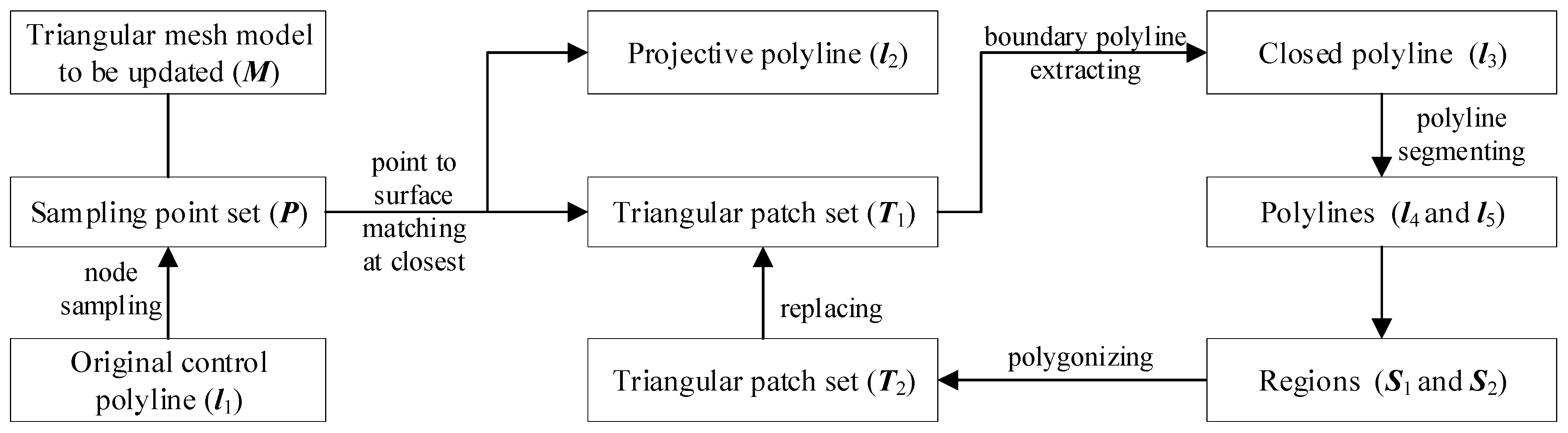
According to the updating idea of 3D orebody mesh reconstruction and mesh deformation, as shown in Figure 1, the model-updating method was divided into five main steps:
Step 1 (preprocessing of geological data): The newly obtained geological logging data were transformed into control polylines and control points to obtain geometric constraint information with consistent topology.
Step 2 (mesh reconstruction of feature preservation): Based on feature detection, the original input mesh model was reconstructed with feature preservation to obtain a better mesh model with high quality.
Step 3 (construction of deformation constraints): The deformation constraints of the orebody model were constructed by matching the deformation points through the control polylines. Furthermore, a similar path with the same number of points was searched on the orebody mesh model based on the control points sampled on the control polylines.
Step 4 (optimization of updating deformation neighborhood region): The mesh area that allowed deformation near the deformation points was optimized and adjusted according to the distance between the model and control polylines, the morphological characteristics of the model and local deformation trend, etc.
Step 5 (constrained mesh deformation): Combined with Laplace coordinate transformation and other methods, the locally updated orebody model was obtained based on the optimized local updating deformation neighborhood region.
Finally, the mesh simplification and mesh repairing of the updated orebody model were carried out to obtain a valid mesh model that satisfied the manifold characteristics. We will describe each step in detail in the following sections. In the Results section, the real data will be tested and analyzed. In the Discussion section, we will analyze the limitations and extensions of this method.

2.1. Preprocessing of Original Geological Data

Before updating the orebody model locally, first, the geological interpretation lines and points obtained from the original geological logging data needed to be preprocessed with de-weighting and simplification to construct topologically consistent geometric constraint information. Second, all valid geological interpretation lines and points needed to be transformed into control polylines and control points, respectively, so that we could construct deformation constraints based on control polylines and control points in the later stage.
In addition, it was necessary to adjust the intersection position of control polylines to ensure the accurate intersection of each control polyline, so that the updated orebody model could snap all control polylines accurately. Furthermore, we used the spatial searching method (e.g., the OBB tree) to speed up the calculation of the exact intersection points between all control polylines.
In the stage of constructing deformation constraints, the optimal deformation point corresponding to the control point was searched according to the corresponding projection direction. To ensure that the model updating effect satisfied the geological characteristics, geological engineers were allowed to adjust the projection direction of the control polylines and points relative to the orebody model.

2.2. Mesh Reconstruction of Geological Models

To ensure that the original input orebody model had a smooth deformation trend and higher mesh quality, mesh reconstruction for the original geological models was important. There were three main problems that needed to be considered, including the size of the mesh reconstruction, the feature protection, and the reconstruction method.
The reconstruction size represents the facet side length of the reconstructed model, and it corresponds to the side length of the triangular patch for the triangular mesh model. In the process of mesh reconstruction, it is better to ensure that the size of mesh reconstruction is less than or equal to the interval of control points sampled on the control polyline. It is worth noting that the reconstructed result should preserve the features of the original model. Therefore, it was necessary to automatically extract the sharp features of the mesh model through the feature detection algorithm, including feature lines and feature points. In addition, artificial additional feature lines and points were allowed to ensure the quality of geological models after mesh reconstruction, such as the alignment of the original model edge, and the retention of the crease feature between patches.
In this paper, we used the implicit reconstruction method while taking feature preservation into account. It transformed feature lines and feature points into constraint lines and constraint points as spatial interpolation constraints and implicitly expressed the geometric model of orebody through the implicit function. Finally, the implicit function was transformed into the mesh model by the surface reconstruction method, taking into account feature preservation.

2.3. Construction of Deformation Constraints

The deformation constraints are the precondition and important link for updating a model. We constructed the deformation constraints of the orebody model by matching deformation points with control polylines. The key idea of the algorithm was to search a similar path with the same number of points as the control polyline on the mesh model. Furthermore, it was imperative that the deformation points on the path be adjacent, otherwise, holes could have appeared in the updated model.
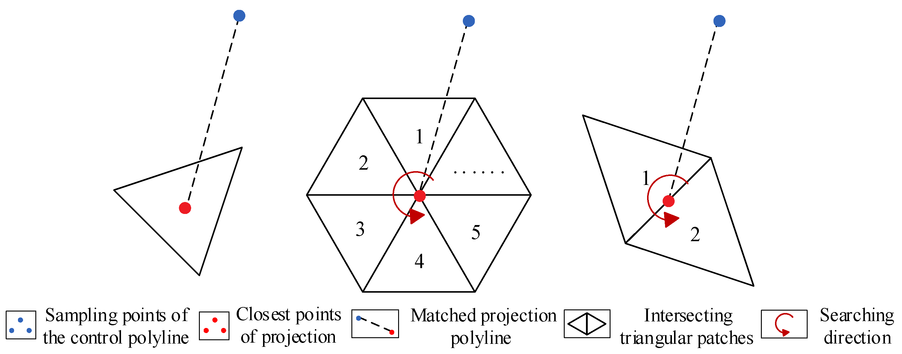
To construct deformation constraints, firstly, we needed to search the closest points of all control points corresponding to the model surface by point projection. Then, the projective polyline corresponding to the control polyline with the same number of points was determined by taking the closest point as the deformation point. The deformation point needed to be the vertex of the mesh. Since the closest projection point may not have been the vertex of the mesh, the projective neighborhood boundary polyline needed to be further extracted from triangular patches where the deformation point and projective polyline were located. Finally, the projective neighborhood was reconstructed by taking the deformation points on the projective polyline as mesh vertices. The detailed steps were as follows, and the process and demonstration are shown in Figure 2 and Figure 3, respectively.
Step 1: Under the condition of reserving all key nodes on the control polyline, the control polyline l 1 was sampled with a certain interval to obtain a set of sampling points P .
Step 2: Traversing the set of sampling points P , the corresponding projective polyline l 2 was obtained by searching the closest points of sampling points on the mesh. Then, a set of connected triangular patches, denoted as T 1 , were obtained, which intersected with the projective polyline.
Step 3: The closed polyline l 3 was obtained by extracting the boundary of the set of the intersecting triangular patches T 1 .
Step 4: The closest points from a start point and an endpoint of the projective polyline l 2 to the closed polyline l 3 , respectively, were searched. Then, the two closest points were used to divide the closed polyline l 3 into two polylines ( l 4 and l 5 ), respectively.
Step 5: The region S 1 between l 2 and l 4 was polygonized. Then, the region S 2 between l 2 and l 5 was polygonized to obtain a new set of triangular patches T 2 , which replaced the set of original triangular patches T 1 .
In Step 2, according to the position of the closest projection point (i.e., deformation point) of the control point to the triangular mesh model, it could be divided into three cases, namely, the vertex, the edge, and the patch of the triangular mesh. Therefore, different methods needed to be adopted to determine the triangular patches, as shown in Figure 4. Firstly, if the deformation point was located at the mesh vertex, the adjacent triangular patches of the mesh vertex within a circle needed to be added to the set T 1 . Secondly, if the deformation point was located on the mesh edge, the two adjacent triangular patches of the mesh edge needed to be added to the set T 1 . Thirdly, if the deformation point was in the triangular mesh patch, the triangular patch needed to be added to the set T 1 .
The triangular patches intersected by all matched projection polylines could be searched according to the method shown in Figure 4. However, it required the searching of all triangular patches on the path of the projective polyline to conduct the subsequent work. In addition, there was an adaptive problem between the control polyline and the mesh model. If the adaptability was adequate, the control points could match the deformation points one by one, and the topological structure of the projective neighborhood triangular meshes was adequate. However, the adaptability was generalized in some conditions, such as the sampling interval being larger than the mesh size, the local shape trend of the model changing greatly, etc. For this case, the topological discontinuity may have occurred in some special locations, which required special methods to deal with. Therefore, we constructed a pseudo-cut surface between two adjacent deformation points, which was automatically generated by three points, including the two adjacent deformation points and the midpoint of two adjacent control points, as shown in Figure 5. Then, the pseudo-cut surface intersected with the mesh model, and the intersecting triangular patches were extracted as a subset of T 1 . Finally, all triangular patches between the deformation points could be extracted to maintain the topological continuity of the projective neighborhood.
It should be noted that the interlacing of matched projection polylines could easily have led to the self-intersection of the model after deformation. In the matching process between control points and deformation points, we needed to ensure one-to-one correspondence between points to avoid the phenomenon of cross-matching or repeated matching.

2.4. Determination and Adjustment of Deformation Neighborhood Region

To determine the local updating deformation neighborhood region of the model, we utilized a method of constructing the deformation neighborhood region based on the specified ring radius of the deformation point. For this method, the value of ring radius was used to quantify the neighborhood radius, and the greedy search strategy was used to automatically search the deformation neighborhood region around the deformation point, as shown in Figure 6.
Generally, if the control polyline was close to the model, the neighborhood radius should have been small. If the control polyline was far away from the model, the neighborhood radius should have been large. To determine the optimal deformation neighborhood region of the mesh model, it was necessary to analyze the characteristics of the optimal deformation neighborhood region. Firstly, the size of the deformation neighborhood region needed to take into account the distance between the control polyline and the model. Secondly, the mesh deformation trend of the deformation neighborhood region needed to be adapted to the shape feature of geological models. Thirdly, the geological models needed to maintain reasonable characteristics and transition in the deformation neighborhood region before and after deformation. Based on the above analysis, the geological engineers could interactively adjust the initial deformation neighborhood region according to the actual conditions, as shown in Figure 7.

2.5. Constraint Deformation and Mesh Simplification

Based on the matched deformation constraints, we could conduct the local dynamic updating of the orebody mesh model based on the Laplace transformation method. The deformation method involved a set of control points used to control the external shape trend in the model updating process, a set of triangular mesh vertices (i.e., deformation points or deformation control points) from the projection of control points to control model deformation, a set of vertices of deformation regions (i.e., ROI), and a set of non-deformation points (i.e., non-deformation control points) in ROI.
We specified a unique target position for each deformation point, and the target position was determined according to the matching relation between the deformation point and the control point. The deformation constraint was defined at the target position of each deformation point. During the deformation process, the coordinates of the non-deformation points were updated by the deformation algorithm, which adopted the Laplace deformation algorithm.
The essence of Laplace mesh deformation is the obtaining of the 3D coordinates of each mesh vertex by solving the linear equations. In this way, a new 3D model can be reconstructed after obtaining new coordinates by solving the equations. The Laplace representation of points in surface mesh (i.e., Laplace coordinates) is a method used to encode the local neighborhood of vertices in surface mesh. In this representation, a vertex v i is associated with a 3D vector, which is defined as follows:
L ( v i ) = v j N ( v i ) w i j ( v i v j )
where N ( v i ) is the set of vertices adjacent to v i , and w i j is the weight of the directed edge v i v j .
In addition, we simplified the mesh model by constructing mesh simplification constraints without changing the quality of the overall mesh model. Specifically, the triangular meshes around the control polyline were not simplified, while the remaining meshes were simplified by merging the fine meshes.
Finally, to ensure the validity of the mesh model after local updating, the method supported the validity detection of the mesh model. Furthermore, the self-intersecting triangular patches could be repaired, and the manifold valid characteristics that satisfied the orebody model could be obtained.

3. Results

3.1. Example

Based on the above algorithms such as mesh reconstruction and mesh deformation, we implemented the local updating method of the geological mesh model using Microsoft Visual Studio 2013 (C++ language) (Microsoft, Redmond, USA). We tested the method on several real geological datasets for local dynamic updating of the orebody model. The datasets were obtained from the real-world geological modeling data.
The following parameters needed to be determined, such as the sampling interval of the control polyline d s a m , the facet side length of the model reconstruction l r e c and the ring radius of the deformation point r d e f . We used the following initial values for all real-world examples: d s a m = 1 ~ 10 , l r e c = 1 ~ 10 d s a m , r d e f = 1 ~ 50 . The surface accuracy of model reconstruction was controlled by the value of l r e c . The smaller the value l r e c , the higher the accuracy. r d e f was used to adjust the overall range of model updating. The larger the value r d e f , the larger the update range.
According to the method, we carried out local dynamic update tests on the orebody models and geological body models, respectively, as shown in Figure 8 and Figure 9. To prove the applicability of this method, we selected three orebody models with different geometric complexities for the modeling experiments shown in Figure 8. The experimental process was as follows. Firstly, the original geological data were processed to obtain the control polylines, and the nodes were sampled. Secondly, the original model was reconstructed to make its mesh size less than or equal to the sampling interval of the control polylines. Thirdly, the control polylines were projected and matched the deformation points. Then, the updating neighborhood region was determined and adjusted according to the deformation points and the value of the specified ring radius. Finally, the model was updated locally by mesh deformation.
Figure 8a shows three types of control polylines, including the closed polyline, the non-closed polyline and the intersected polyline. It shows that the geometric shape of the model changed a little before and after mesh reconstruction in Figure 8b, indicating that the reconstruction effect was satisfied. When the control polyline was projected, the matching effect between control points and deformation points was appropriate, and the neighborhood search, according to the ring radius of the deformation point, also performed well, as shown in Figure 8c. After the model was updated, the comparison of the points before and after the update showed that the updating method only deformed and updated the mesh model in the local range, which had achieved the expected effect, as shown in Figure 8d.
To demonstrate the robustness of the method for different types of geological models, we also conducted experimental tests on a geological body model, as shown in Figure 9. We inputted several intersecting polylines as control polylines. The experimental results show that the method also had advantages in terms of updating the geological body mesh model, the topology was maintained well, and the updated model still had manifold characteristics. In summary, the method was beneficial in solving the local dynamic updating problem of the orebody models and geological body models.

3.2. Performance

The performance of the updating method mainly depended on the size of the original model and the number of control polylines. We implemented the algorithm in C++ and tested it on a Windows 64-bit PC (ASUS, Taibei, China) with a 3.40GHz Intel(R) Core (TM) i5-8250U processor and 4GB RAM. Table 1 reports the parameters and running time of the mesh reconstruction and updating stages of the algorithm on these examples. It shows that larger numbers of triangular patches and control polylines required longer calculation timed. The size of the updating neighborhood region also affected the quality and speed of updating.

4. Discussion

4.1. Limitations

To make the process of orebody modeling and updating more automated and intelligent, it is necessary to establish a more automated, efficient, and robust local dynamic updating method. However, there are still some limitations to our work that need to be improved.
One of them is that the method proposed in this paper may be unsuitable for some special conditions. Firstly, the large difference between the control polylines and the model may lead to an abnormal matching between control points and deformation points. Secondly, if a control polyline is too long, the neighborhood radius may not satisfy the deformation trend. Thirdly, if the model or control polyline is complex, the matched projection polyline may be abnormal, resulting in distortion of the model after deformation. Therefore, based on the limitations of this method, to ensure the mesh quality, we should divide a complex control polyline into several segment lines and update the complex model iteratively.
Another limitation to this method is that, for orebody models with special shapes, or at special positions within the model, there may be feature loss during model updating. On the one hand, if there are many concave and convex shapes on the model surface, many detailed features may be lost after updating. On the other hand, if the model is updated at sharp points or the model is thin, the sharp features of the model may be lost. Therefore, for this kind of special orebody model, the defining of strict sharp feature constraint lines and points should be considered to ensure that these features can be retained.

4.2. Extensions

To enhance the robustness and adaptability of this method, it is necessary to satisfy the requirement of the algorithm for the inputs. Our approach requires that the input data should be a set of geological interpretation data and an orebody mesh model to be updated. When the orebody model is reconstructed, the shape of the model may change to a certain extent. An important extension is that only the deformation region is reconstructed, which can improve the quality of model updating. In this paper, there are some examples of mesh reconstruction for some regions, such as the mesh reconstruction of the projective neighborhood, which reflects the feasibility of this extended idea. Furthermore, this method is not only applicable to the orebody model but is also applicable to some other surface mesh models such as the orebody model. It is also applicable to the updating of the solid model, and thus, is not limited only to the surface mesh model.
Another important extension is that, according to the particularity of some models and the complexity of control polylines, we can study more abundant and reliable deformation constraint methods to improve not only the adaptability and robustness of the model-updating method but also the quality and efficiency of model updating. The particularity of the model can be reflected in the special morphology (e.g., the thin orebody or the orebody with many morphological changes), the special updating area (e.g., the position with sharp or large fluctuation of the model), etc. The complexity of control polylines includes intensive polylines, irregular polylines, lengthy polylines, etc. Therefore, we can define some additional constraint data according to different situations, improve the model-updating method, and make the model-updating method more adaptable and more robust.

5. Conclusions

In this paper, we present a local dynamic updating method of the orebody model that allows the interactive addition of constraint deformation conditions and dynamic updating of the mesh model in the updating process. Our main contribution is based on the model-updating idea of mesh reconstruction and mesh deformation. The local updating process of the orebody model is regarded as a local constrained deformation process of the mesh model. Moreover, we present a local dynamic updating method of the orebody model and implement a constrained mesh deformation algorithm of the orebody model. This method can automatically update a given 3D orebody model based on a set of unordered geological interpretation polylines.
The orebody modeling is a dynamic process that is gradually refined with the continuous enrichment of geological exploration data. If the geological data of orebody changes locally, it is necessary to re-interpret the contour polylines, delineate the sections, and splice the parallel or non-parallel sections. Furthermore, it is difficult to satisfy the requirements of resource reserve estimation and dynamic updating of the orebody model in the production and exploration stage. According to the method, structural geologists can reconstruct the mesh model, construct deformation constraints according to the new geological interpretation data, and dynamically update the model by mesh deformation in the local region of the model.

Author Contributions

Z.L., D.Z., Z.W., L.W. and Q.T. conceived, designed, and performed the experiments; D.Z. and Z.L. analyzed the data and revised the methodology; Z.L. wrote the paper; all authors discussed the results and revised the paper. All authors have read and agreed to the published version of the manuscript.

Funding

This work was financially supported by the National Key R&D Program of China (2017YFC0602905) and the Fundamental Research Funds for the Central Universities, granted to Central South University (2021zzts0869).

Data Availability Statement

Not applicable.

Acknowledgments

Gratitude is expressed for the public datasets used in this research. We also thank the reviewers for their comments and suggestions to improve the quality of the paper.

Conflicts of Interest

The authors declare no conflict of interest. The funders had no role in the design of the study; in the collection, analyses, or interpretation of data; in the writing of the manuscript, and in the decision to publish the results.

References

  1. Sherstyuk, A. Fast Ray Tracing of Implicit Surfaces. Comput. Graph. Forum 1999, 18, 139–147. [Google Scholar] [CrossRef]
  2. Li, C.; Li, F.; Guo, J.; Liu, C.; Liu, Y. 3D geological map modeling technology based on a geological route and geological object wireframe model. Acta Geol. Sin. Engl. Ed. 2019, 93, 231–235. [Google Scholar]
  3. Huang, J.; Zhang, H.; Shi, X.; Liu, X.; Bao, H. Interactive mesh deformation with pseudo material effects. Comput. Animat. Virtual Worlds 2006, 17, 383–392. [Google Scholar] [CrossRef] [Green Version]
  4. Sun, J.; Ding, Y.; Huang, Z.D.; Wang, N.; Zhu, X.L.; Xi, J.T. Laplacian deformation algorithm based on mesh model simplification. In Proceedings of the 3rd IEEE International Conference on Image, Vision and Computing (ICIVC), Chongqing, China, 27–29 June 2018; pp. 209–213. [Google Scholar]
  5. Cowan, E.J.; Spragg, K.J.; Everitt, M.R. In wireframe-free geological modelling—An oxymoron or a value proposition? In Proceedings of the AusIMM Eighth International Mining Geological Conference, Queenstown, New Zealand, 22–24 August 2011; Australasian Institute of Mining and Metallurgy: Queenstown, New Zealand, 2011. [Google Scholar]
  6. Guo, J.; Wang, J.; Wu, L.; Liu, C.; Li, C.; Li, F.; Lin, M.; Jessell, M.W.; Li, P.; Dai, X.; et al. Explicit-implicit-integrated 3-D geological modelling approach: A case study of the Xianyan Demolition Volcano (Fujian, China). Tectonophysics 2020, 795, 228648. [Google Scholar] [CrossRef]
  7. Reiner, T.; Mückl, G.; Dachsbacher, C. Interactive modeling of implicit surfaces using a direct visualization approach with signed distance functions. Comput. Graph. 2011, 35, 596–603. [Google Scholar] [CrossRef] [Green Version]
  8. Zhong, D.; Wang, L. Solution Optimization of RBF Interpolation for Implicit Modeling of Orebody. IEEE Access 2020, 8, 13781–13791. [Google Scholar] [CrossRef]
  9. Zhong, D.-Y.; Wang, L.-G.; Bi, L.; Jia, M.-T. Implicit modeling of complex orebody with constraints of geological rules. Trans. Nonferrous Met. Soc. China 2019, 29, 2392–2399. [Google Scholar] [CrossRef]
  10. Manchuk, J.G.; Deutsch, C.V. Boundary modeling with moving least squares. Comput. Geosci. 2019, 126, 96–106. [Google Scholar] [CrossRef]
  11. Guo, J.; Wang, X.; Wang, J.; Dai, X.; Wu, L.; Li, C.; Li, F.; Liu, S.; Jessell, M.W. Three-dimensional geological modeling and spatial analysis from geotechnical borehole data using an implicit surface and marching tetrahedra algorithm. Eng. Geol. 2021, 284, 106047. [Google Scholar] [CrossRef]
  12. Basson, I.; Anthonissen, C.; McCall, M.; Stoch, B.; Britz, J.; Deacon, J.; Strydom, M.; Cloete, E.; Botha, J.; Bester, M.; et al. Ore-structure relationships at Sishen Mine, Northern Cape, Republic of South Africa, based on fully-constrained implicit 3D modelling. Ore Geol. Rev. 2017, 86, 825–838. [Google Scholar] [CrossRef]
  13. Wang, J.; Zhao, H.; Bi, L.; Wang, L. Implicit 3D Modeling of Ore Body from Geological Boreholes Data Using Hermite Radial Basis Functions. Minerals 2018, 8, 443. [Google Scholar] [CrossRef] [Green Version]
  14. Zhong, D.-Y.; Wang, L.-G.; Jia, M.-T.; Bi, L.; Zhang, J. Orebody Modeling from Non-Parallel Cross Sections with Geometry Constraints. Minerals 2019, 9, 229. [Google Scholar] [CrossRef] [Green Version]
  15. Guan, B.; Lin, S.; Wang, R.; Zhou, F.; Luo, X.; Zheng, Y. Voxel-based quadrilateral mesh generation from point cloud. Multimed. Tools Appl. 2020, 79, 20561–20578. [Google Scholar] [CrossRef]
  16. Zhong, D.; Zhang, J.; Wang, L. Fast Implicit Surface Reconstruction for the Radial Basis Functions Interpolant. Appl. Sci. 2019, 9, 5335. [Google Scholar] [CrossRef] [Green Version]
  17. Guo, J.; Wu, L.; Zhou, W.; Li, C.; Li, F. Section-constrained local geological interface dynamic updating method based on the HRBF surface. J. Struct. Geol. 2018, 107, 64–72. [Google Scholar] [CrossRef]
  18. Zhong, D.-Y.; Wang, L.; Bi, L. Implicit surface reconstruction based on generalized radial basis functions interpolant with distinct constraints. Appl. Math. Model. 2019, 71, 408–420. [Google Scholar] [CrossRef]
  19. Wang, Z.; Cheng, J. Research and Implementation of Mesh Model Deformation Simulation Technology. J. Phys. Conf. Ser. 2020, 1575. [Google Scholar] [CrossRef]
  20. Yan, W.U.; Zhu, C. Design of Triharmonic Triangular Bezier Surfaces. Math. Res. Appl. 2021, 41, 425–440. [Google Scholar]
  21. Wu, J.; Wang, R. Approximate implicitization of parametric surfaces by using compactly supported radial basis functions. Comput. Math. Appl. 2008, 56, 3064–3069. [Google Scholar] [CrossRef] [Green Version]
  22. Zhong, D.-Y.; Wang, L.-G.; Wang, J.-M. Combination Constraints of Multiple Fields for Implicit Modeling of Ore Bodies. Appl. Sci. 2021, 11, 1321. [Google Scholar] [CrossRef]
  23. Toufigh, V. Constrained optimization based F.E. mesh deforming algorithm for unconfined seepage problems. Appl. Math. Model. 2016, 40, 6754–6765. [Google Scholar] [CrossRef]
  24. Cetinaslan, O. Localized constraint based deformation framework for triangle meshes. Entertain. Comput. 2018, 26, 78–87. [Google Scholar] [CrossRef]
  25. Shi, Z.; Qian, K.; Yu, K.; Luo, X. A new triangle mesh simplification method with sharp feature. In Proceedings of the 2018 7th International Conference on Digital Home (ICDH), Guilin, China, 30 November–1 December 2018; pp. 324–328. [Google Scholar] [CrossRef]
  26. Qin, X.; Wu, T.; Liu, Y.; Lu, Y. Research and Application of Example-Driven Surface Deformation Method. Chin. J. Electron. 2019, 28, 85–92. [Google Scholar] [CrossRef]
  27. Alexa, M. Differential coordinates for local mesh morphing and deformation. Vis. Comput. 2003, 19, 105–114. [Google Scholar] [CrossRef]
  28. Feng, X.; Shi, M.Y. In Surface Representation and Processing. In Proceedings of the 8th IEEE International Conference on Cognitive Informatics (ICCI 2009), Hong Kong, China, 15–17 June 2009; pp. 542–545. [Google Scholar]
  29. Lyu, W.; Wu, W.; Zhang, L.; Wu, Z.; Zhou, Z. Laplacian-based 3D mesh simplification with feature preservation. Int. J. Model. Simul. Sci. Comput. 2019, 10, 19500028. [Google Scholar] [CrossRef]
  30. Liu, L.; Tai, C.-L.; Ji, Z.; Wang, G. Non-iterative approach for global mesh optimization. Comput. Des. 2007, 39, 772–782. [Google Scholar] [CrossRef] [Green Version]
  31. Karade, V.; Ravi, B. 3D femur model reconstruction from biplane X-ray images: A novel method based on Laplacian surface deformation. Int. J. Comput. Assist. Radiol. Surg. 2014, 10, 473–485. [Google Scholar] [CrossRef]
  32. Xu, C.; Yang, X.; Liu, X. Nonrigid point set registration based on Laplace mixture model with local constraints. Assem. Autom. 2019, 40, 335–343. [Google Scholar] [CrossRef]
Figure 1. Local dynamic updating method of the orebody model based on mesh reconstruction and mesh deformation.
Minerals 11 01232 g001
Figure 2. Mesh reconstruction flowchart of the projective neighborhood.
Minerals 11 01232 g002
Figure 3. Schematic diagram of mesh reconstruction in the projective neighborhood.
Minerals 11 01232 g003
Figure 4. Determination of the intersecting triangular patches according to the projection position of control points.
Minerals 11 01232 g004
Figure 5. Determination of the intersecting triangular patches between the deformation points by constructing pseudo-cut surfaces. The vertices of the pseudo-cut surface are represented by ’ a ’ to ‘ c ’. The added triangular patches are represented by ‘ 1 ’ to ‘ 5 ’.
Minerals 11 01232 g005
Figure 6. The determination of the initial deformation neighborhood region based on the ring radius of the deformation points. (a) Deformation points and projective polylines; (b) Ring radius (R) of deformation neighborhood region.
Minerals 11 01232 g006
Figure 7. The determination, adjustment, and optimization of deformation neighborhood region (af).
Minerals 11 01232 g007
Figure 8. Three examples of the local updating of orebody models (ad): (1) the first example; (2) the second example; (3) the third example.
Minerals 11 01232 g008
Figure 9. An example of the local updating of a geological body model (ad).
Minerals 11 01232 g009
Table 1. The parameters and running time for the experiment examples, including the number of model facets ( N 1 ), the number of control polylines ( N 2 ), the reconstruction time ( R E C ), and the updating time ( U P D ).
Examples N 1 N 2 d s a m ( m ) l r e c ( m ) r d e f Time (s)
R E C U P D
Figure 8(1)13,18851194.791.08
Figure 8(2)29,4203101098.330.92
Figure 8(3)59,4446111511.0114.47
Figure 992,5477112069.8965.96
Publisher’s Note: MDPI stays neutral with regard to jurisdictional claims in published maps and institutional affiliations.

