Article

Design Optimization of Eccentric Pole PM Motors Using the Bilinear Mapping Method

1
Manufacturing and Production Department, Faculty of Engineering, Arak University, Arak 3848177584, Iran
2
Université Marie et Louis Pasteur, UTBM, CNRS, Institut FEMTO-ST, F-90010 Belfort, France
*
Author to whom correspondence should be addressed.
Symmetry 2026, 18(2), 368; https://doi.org/10.3390/sym18020368
Submission received: 28 December 2025 / Revised: 5 February 2026 / Accepted: 12 February 2026 / Published: 16 February 2026
(This article belongs to the Special Issue Computational Mathematics and Its Applications in Numerical Analysis)

Abstract

The eccentric permanent-magnet (PM) pole technique is widely recognized as an effective technique for reducing cogging torque in surface-mounted PM motors (SMPMMs). This paper proposes a novel analytical approach based on bilinear mapping to determine the optimal PM reduction parameters. In this method, the outer surface of the PM and the stator inner bore are modeled as eccentric circles. Bilinear mapping is then used to transform a slotted stator bore into an equivalent slotless configuration with small slot-openings, allowing the optimal PM reduction to be identified. The key electromagnetic performance characteristics of SMPMMs—including torque, efficiency, mean air-gap flux density, and related parameters—are formulated as explicit mathematical functions of the PM reduction factor. The influence of the optimal PM reduction on both static and dynamic rotor eccentricity is also investigated. The results reveal that the bilinear mapping equations yield two distinct roots for the optimal PM reduction. Once the optimal values are known for a reference motor, those of other motors with different dimensions can be readily derived by scaling according to the ratio of the outer PM radii, without repeating the full calculation process. The proposed method is applicable to various SMPMM geometries, including radial, parallel, and bread-loaf configurations.

1. Introduction

The eccentric PM pole technique is an effective method for improving the air-gap magnetic flux density distribution and consequently reducing both the amplitude and harmonics content of the cogging torque in SMPMMs. This method involves offsetting the center of the stator surface circle, reducing the PM thickness, and increasing the PM arc angle. However, determining the optimal eccentric radius (PM edge thickness) and eccentric angle remains a major challenge.
In recent years, researchers have tried to estimate the performance of PM motors by modifying the PM shape from the conventional design using (semi-)analytical and/or numerical methods.
PM shapes studied by other researchers can be classified as:
  • Eccentric PM pole shape [1,2,3,4,5,6,7,8,9,10,11,12,13,14,15];
  • Isodiametric eccentric PM pole shape [16];
  • Asymmetric PM pole shape [17];
  • Discrete skew angle PM pole shape [18];
  • Loaf/regular arc PM shape [19];
  • Tapered/chamfered cut PM pole shape [20,21,22];
  • Sinusoidal pulse-width modulation PM pole shape [23];
  • Trapezoid PM pole shape [24];
  • Arc-shape PM pole shape/inverse cosine air-gap length PM pole shape/bread loaf PM pole shape [25,26,27];
  • Trilateral, rounded and sine PM pole shape [28];
  • Free form PM pole shape [29,30].
PM shape modeling is carried out by using several well-known (semi-)analytical approaches, such as the subdomain method (SDM) [1,2,3,4,5,6,19,20,24], equivalent magnetic circuits [7], parametric design [8], the energy method and Fourier expansion [16], Schwarz–Christoffel mapping [17], fundamental relations with Fourier expansion [23,25,26,27,28], the minimum rotor angle method, and the mono-tooth method [29]. The main ideas in these pieces of researchpieces of research are based on PM segmentation [1,2,3,4,5,20,21], the surface current/coil method [6,19,24], sinusoidal PM segmentation [23], third-harmonic PM shaping [25,26,27] and sine PM shaping [28]. In some pieces of research, the numerical finite-element method (FEM) is used for PM shape modeling [9,10,11,12,13,14,15,18,22,30].
The validation of analytical/numerical results is often carried out by FEM [1,2,3,4,5,6,7,8,11,16,17,18,19,20,21,23,24,25,26,27,28,29,30] or measurement [3,5,7,9,10,14,18,19,22,23,24,27].
Performance considerations include the following:
PM shape optimization algorithms/methods include particle swarm optimization [2], the parametric sweep analytical method [4,5,7,23,28], the parametric sweep FEM method [9,10,11], the self-organizing migrating algorithm [12], genetic algorithms [17,18,30], SDM and FEM [21], time stepping adaptive FEM [22], and the level set based topology method [29]. In single-objective optimization works, harmonics of magnetic field and hence iron losses [4], torque ripple [5,21], sinusoidal back-electromotive force (back-EMF) waveform [7,10], cogging torque [9,18,28,29,30,31], and efficiency [22] are considered as objective. In multi-objective optimizations, PM volume and cogging torque [2], average torque and torque ripple [11], total harmonic distortion (THD), torque, efficiency and losses [12], average/cogging/ripple torque [17], PM volume, motor torque, and efficiency [23] are considered as objective.
Some mathematical relation for PM shape is expressed in the form of cosine-shaped PM [4], sine-shaped PM [14], third harmonic injected sinusoidal-shaped PM [14], and sine-shaped PM and third harmonic injected sinusoidal-shaped PM [25,26,27]. It is important to distinguish the primary objective of the eccentric pole technique from other shaping methods, such as third-harmonic injection [32,33]. While third-harmonic shaping primarily aims to tailor the air-gap flux density waveform to improve average torque or reduce torque ripple under load, the core objective of the eccentric pole method explored here is the minimization of cogging torque by mitigating the interaction between the slot openings and the PM field. This work focuses on deriving the optimal geometry for this latter purpose. A comparative analysis of the resultant torque profiles would be a valuable subject for future work.
In this research, the bilinear mapping approach is used to determine the optimal PM reduction for minimizing cogging torque. The main idea in this method is that the outer circle of the PM and the inner circle of the stator are considered as eccentric circles relative to each other. According to the relations extracted by Gieras [34] for calculating cogging torque, the cogging torque tends to zero when the slot-opening width tends to zero. This is because the amount of interaction of the PM rotor magnetic field at all points on a slotless stator becomes uniform. Accordingly, the problem is reduced to finding a bilinear mapping that transforms a slotted stator bore into an equivalent slotless bore with near-zero slot openings. This is achieved by applying the bilinear mapping in reverse, starting from an assumed slot opening width close to zero. The corresponding stator slot pitch is then calculated, and the process is repeated until the roots of the resulting equations are obtained, yielding the optimal PM reduction and curvature radius.

2. Problem Definition

2.1. Description

The analytical model presented in this study is based on a two-dimensional (2-D) cross-sectional analysis. This is a standard and valid approach for radial-flux machines, as it assumes a uniform magnetic field distribution along the axial direction. This simplification allows the core electromagnetic relationships governing cogging torque and performance to be derived from the machine’s cross-sectional geometry, which is the primary focus of the PM shape optimization.
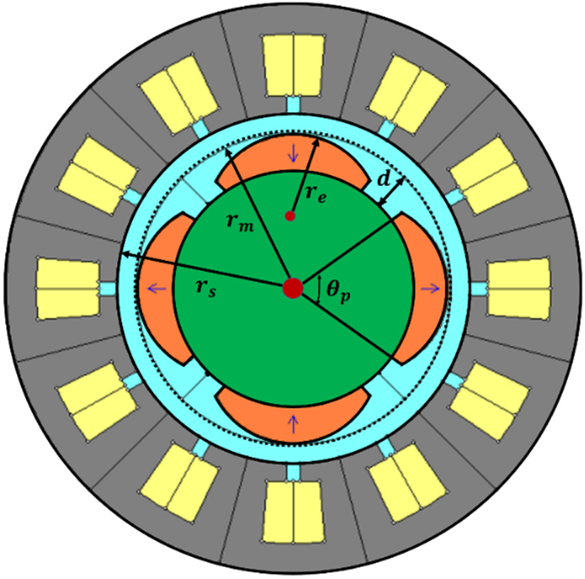
Figure 1 illustrates the cross-section of an SMPMM with eccentric PM pole shapes. The outer profile of the PM is defined by the following parameters:
  • d : PM reduction ( 0 < d < d m a x where d m a x is the maximum PM length at the center of the pole along the d -axis);
  • θ p : PM angular span;
  • r e : Radius of the outer rounded PM profile;
  • r m : Radius of the outer profile of the PM at the center of the pole;
  • r s : Inner radius of the stator;
  • l : PM eccentricity (where l = r m r e ).
We can find the radius and eccentricity of the PM’s outer circle relative to the stator’s inner circle by:
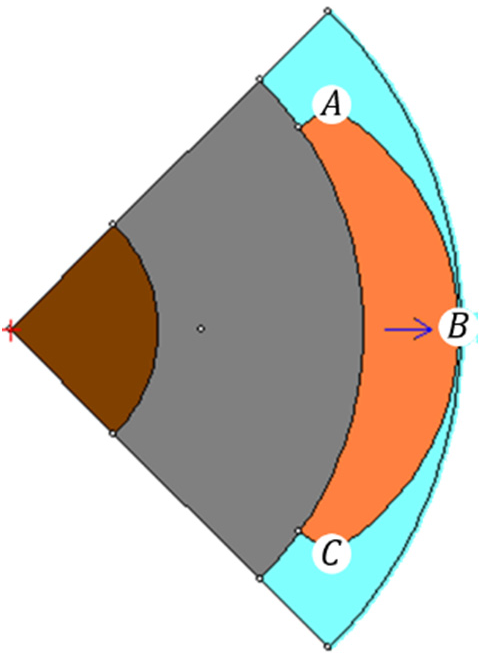
  • Considering three points (A, B and C) on the PM’s outer profile as shown in Figure 2;
  • Finding the equation of the circle passing through these points;
  • Using the equation to determine the radius r e and eccentricity l based on the PM’s edge thickness.
This simplifies the process and clarifies the steps involved.
A = r m d cos θ p 2 r m d sin θ p 2
B = r m 0
C = r m d cos θ p 2 r m d sin θ p 2
The coordinates of point B demonstrate that despite the PM’s deformation, its position at that point and its central thickness remain unaltered. This is a constraint that is considered in all stages of optimization.
l = d ( 2 r m d ) 2 r m 2 r m d cos θ p 2
r e = r m l
The greatest value of the angle θ occurs when all the magnetic poles are in direct contact. This angle, measured in mechanical degrees, can be calculated by:
θ m a x = 360 p
where p is the number of poles of the SMPMM.
The minimum value of the angle θ is achieved when the eccentricity radius is equal to the PM thickness, given the constraint of constant thickness in the PM’s center. This minimum θ can be calculated by:
θ m i n = 2 c o s 1 2 r m 2 4 r m d m a x + d m a x 2 2 r m d m a x 2
Therefore, the following constraint must be considered in the optimization process, viz.,
θ m i n θ θ m a x

2.2. Model Assumptions and Validity

2.2.1. Electromagnetic Assumptions

  • 2-D Field: The magnetic field is assumed invariant along the axial direction (z-axis), reducing the problem to a 2-D cross-sectional analysis;
  • Linear Material Properties: The stator and rotor iron cores are assumed to have infinite permeability ( μ i r o n + ), and the PMs are modeled with a linear recoil permeability μ r m . Magnetic saturation is not accounted for in the analytical derivations;
  • Slot-Leakage Field: In the initial bilinear mapping transformation, the magnetic field in the immediate vicinity of the slot-openings is approximated, with detailed slot-leakage effects considered secondary for the cogging torque minimization mechanism.

2.2.2. Geometric and Operational Constraints

  • PM Reduction Limit: The physical reduction in PM edge thickness is bounded: 0 < d < d m a x where d m a x is determined by mechanical integrity;
  • Pole Arc Limit: The PM angular span is constrained by θ m i n θ θ m a x ensuring physically realizable poles;
  • Eccentricity Type: The analytical formulation for rotor eccentricity in Section 4 specifically addresses static eccentricity. The model is valid within typical manufacturing tolerance levels of eccentricity.

3. Cogging Torque Calculation in Concentric Rotor PM Motor

The analytical model for cogging torque calculation is based on the energy method and follows the formulation introduced by Gieras [34]. In this model, the torque is obtained as the derivative of the magnetic energy stored in the air-gap with respect to the rotor position. The formulation considers two dominant harmonic interaction components:
  • The interaction between the fundamental PM magnetomotive force and the slot permeance harmonics K 1 X ;
  • The self-interaction of the slot permeance harmonics K 2 ( X ) .
In contrast, the novel contribution of this paper is to use a geometric transformation to invert this problem: to solve for the optimal rotor geometry that minimizes the slot-effect terms within this very T c X equation. The cogging torque for a concentric rotor motor is given by:
T c X = L i g 2 μ 0 D o u t 2 K 1 X + K 2 ( X )
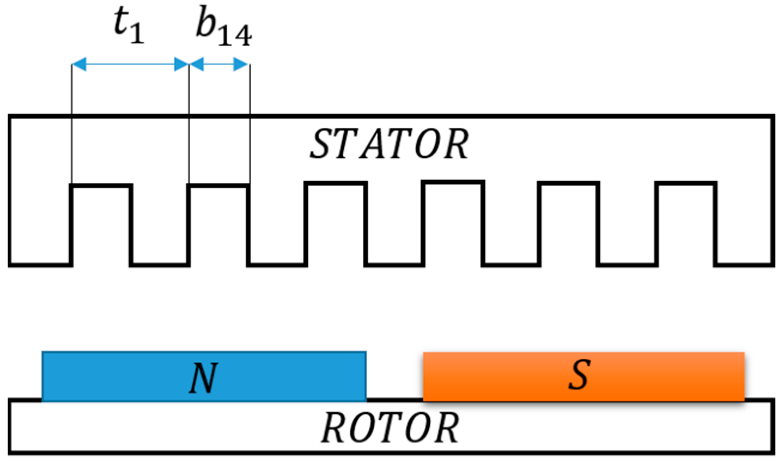
where X represents the angular position of the rotor relative to the stator (serving as the independent variable that defines the periodic variation of the cogging torque during the rotor rotating), L i is the stack length, g is the air-gap length, μ 0 is the magnetic permeability of vacuum, D o u t is the rotor outer diameter, and the functions K 1 X and K 2 X   depend on the slot-opening width b 14 and the slot-pitch t 1 (shown in Figure 3), viz.,
K 1 X = 4 k C A B g 2 s i n α X + a + b 2 s i n α a b 2
K 2 X = A 2 B g 2 s i n 2 α X + a + b 2 s i n α ( a b )
where B g is the maximal amplitude of the air-gap magnetic flux density, α = 2 π / t 1 , a = 0.5 t 1 , b = 0.5 b 14 + c t , c t = t 1 b 14 , and
A = 2 γ g t 1 k o k 2
with
γ = 4 π b 14 2 g a t a n b 14 2 g l n 1 + b 14 2 g 2
k o k = s i n k ρ π b 14 2 t 1 k ρ π b 14 2 t 1
ρ = b 14 t 1 5 + b 14 t 1 2 1 + b 14 t 1 2 1 + b 14 t 1 2 1
The Carter’s factor for slotted electric machines was calculated in [35] with
k C = 1 1 2 b 14 t 1 π a . t a n b 14 2 g g b 14 l n 1 + 1 4 b 14 g 2
The key parameters in these expressions, such as the factor A , directly depend on the slot-opening width b 14 . The core mathematical insight is that as b 14 0 , the factor A 0 , and consequently, the cogging torque vanishes. This fundamental observation forms the basis of the PM shaping strategy proposed in this paper.

4. Cogging Torque Calculation in PM Motor with Rotor Eccentricity

The air-gap variation for static eccentricity can be expressed analytically as [34]
g x = g 1 ε . c o s x
where ε = e / g . In this formulation, x represents the angular coordinate along the air-gap circumference, defining the spatial variation of the non-uniform air-gap due to static eccentricity. This variable is different from the rotor position X used in the cogging torque formulation.
The cogging torque can be expressed as
T c X = L i g 2 μ 0 K 1 X + K 2 X + K 3 X + K 4 X + K 5 X
where
K 3 X = 2 1 k C A B g 2 ε s i n ( θ + α ) x + a + b 2 s i n ( θ + α ) x + a b 2 + s i n ( θ + α ) x + a + b 2 s i n ( θ α ) x + a b 2
K 4 X = A 2 B g 2 ε 2 s i n θ x + a + b 2 s i n θ a b 2 + s i n ( θ + 2 α ) x + a + b 2 s i n ( θ + 2 α ) a b 2 + s i n ( θ 2 α ) x + a + b 2 s i n ( θ 2 α ) a b 2
K 5 X = A 2 B g 2 ε 2 1 4 s i n 2 θ + α x + a + b 2 s i n θ + α a b + 1 4 s i n 2 θ α x + a + b 2 s i n θ α a b + 1 2 s i n 2 α x + a + b 2 s i n α a b + 1 2 s i n 2 α x + a + b 2 s i n α a b
The same factor A is present in these additional terms K 3 X , K 4 X and K 5 X confirming that minimizing its effect through PM shaping remains valid under eccentricity.

5. Bilinear Mapping

The bilinear mapping method’s key merit is thus its provision of a direct design rule. Instead of iteratively evaluating T c X for various d values using Equation (9) (an energy method-based approach) to find a minimum, the conformal mapping establishes an explicit, solvable set of equations whose roots directly yield the optimal geometry d o p t that theoretically nullifies the cogging torque mechanism described by the forward model.
For an eccentric annulus, a simple bilinear transformation will be studied here, as shown below [36]:
z = w 1 a w
where z = x + i y , w = ρ e i , and a is a positive real constant.
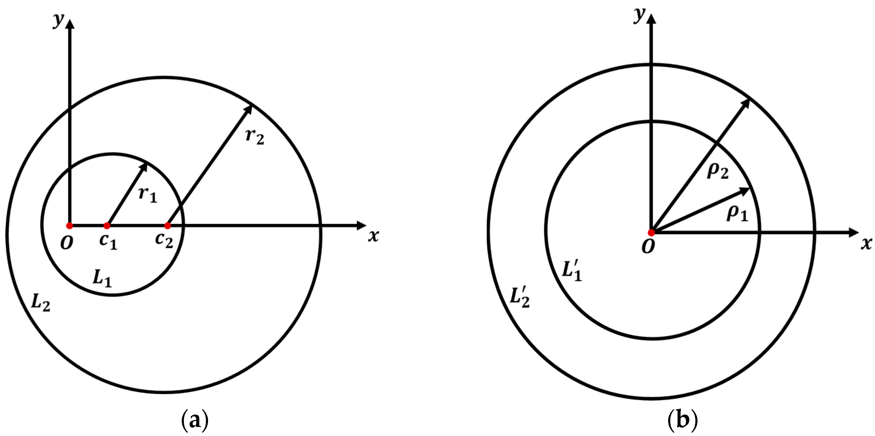
We consider now two circles L 1 and L 2 in the z -plane with radii r 1 and r 2 , respectively, which can be mapped on two circles L 1 and L 2 in the w -plane with radii ρ 1 and ρ 2 , respectively, as illustrated Figure 4. From Figure 1, we can find the circles L in the w -plane with the radius ρ . We can determine the origin of L 1 and L 2 in the z -plane as follow
c i = a r i ρ i  
r i = ρ i 1 a 2 ρ i 2   with   i = 1 , 2
The parameter l represents the distance between the centers of the two circles:
l = c 2 c 1 = ρ 2 1 a 2 ρ 2 2 ρ 1 1 a 2 ρ 1 2
According to three Equations (22)–(24), three unknown constants a , ρ 1 and ρ 2 can be determined by
a = l r 1 2 r 2 2 2 2 l 2 r 1 2 r 2 2 + l 4
ρ 1 = 1 + 4 r 1 2 a 2 1 2 r 1 a 2  
ρ 2 = 1 + 4 r 2 2 a 2 1 2 r 2 a 2
Bilinear mapping enables the transformation of eccentric circles in the z -plane into concentric circles in the w -plane. This property is particularly useful for analyzing slotted stator geometries in the z -plane. By mapping a slotted stator circle to an equivalent slotless circle in the w -plane, the equations can be derived whose real roots directly correspond to the optimal reduction of the PM edge thickness. We can achieve this by reformulating (28) as follows:
2 ρ 2 r 2 a 2 1 + 4 r 2 2 a 2 + 1 = 0
By solving (29), the non-zero values of a are:
a 1,2 = ± r 2 ( r 2 ρ 2 ) r 2 ρ 2
Equation (31) is derived by substituting the specific values of variable a into (26) and then rearranging the resulting expression
a 2 r 1 2 r 2 2 2 2 l 2 r 1 2 + r 2 2 + l 4 l = 0
in which the eccentricity, denoted by l , is determined by the relationship (4).
Upon solving (31) for r 1 , the roots become:
r 1 , j = ± a i ( a i l 2 + a i r 2 2 + 4 a i 2 l 2 r 2 2 + l ) a i   w i t h   i = 1,2   a n d   j = 1 , , 4
and
r 1 , j = ± a i ( a i l 2 a i r 2 2 + 4 a i 2 l 2 r 2 2 + l ) a i   w i t h   i = 1,2   a n d   j = 5 , , 8
The radii of eccentric circles that minimize cogging torque are denoted by r 1 . By setting r 1 = r e   in (32) and (33), and rearranging the resulting equation, the absolute values of the real roots corresponding to the optimal values of d   (representing the reduction in the PM edge thickness) can be obtained from the following relationship:
r e r 1 , j = 0   w i t h   j = 1 , , 8
It is evident that not all eight equations possess real solutions, and some may even yield complex solutions. However, due to the constraint of utilizing only non-complex solutions within the z -plane, the analysis must focus on the absolute values of the real roots of (11). These absolute values, therefore, represent the optimal values of d .

6. Case Study

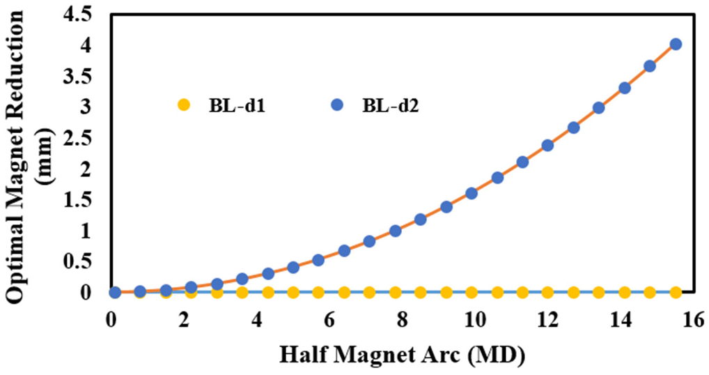
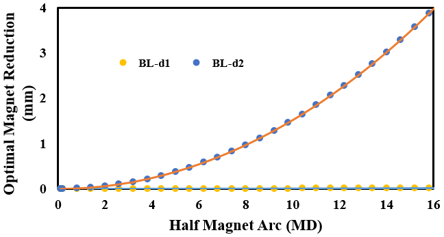
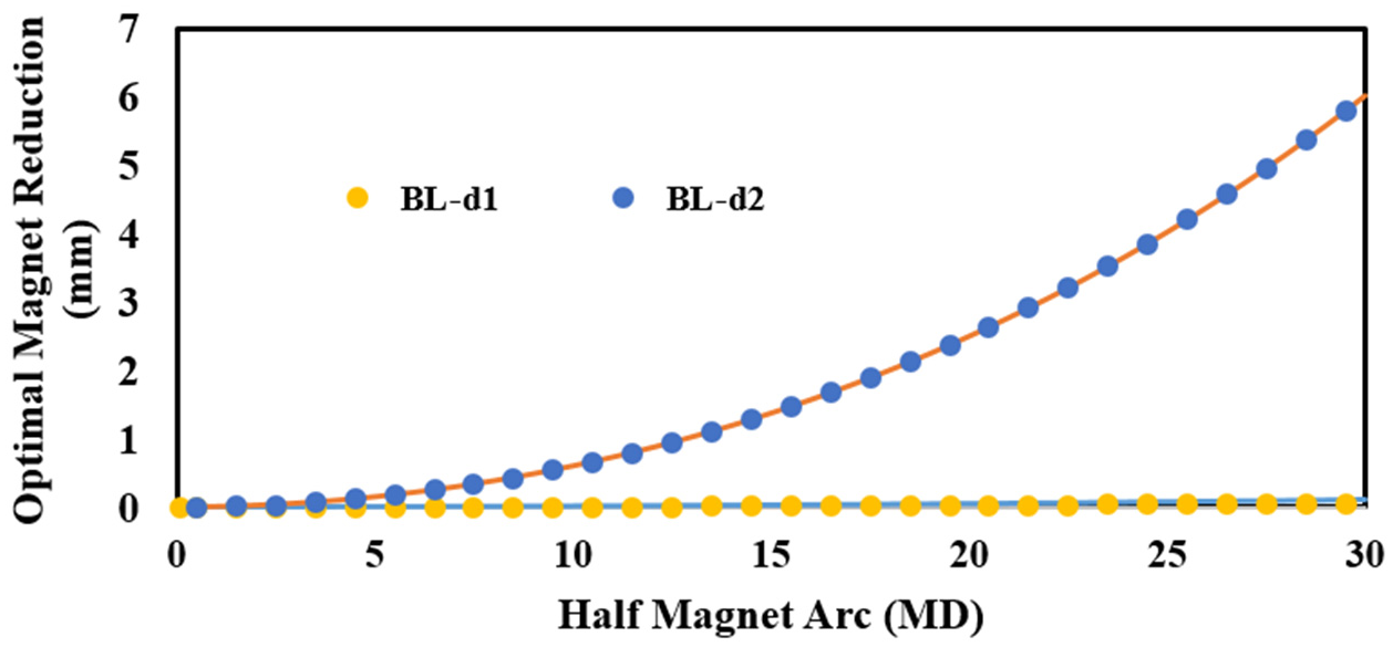
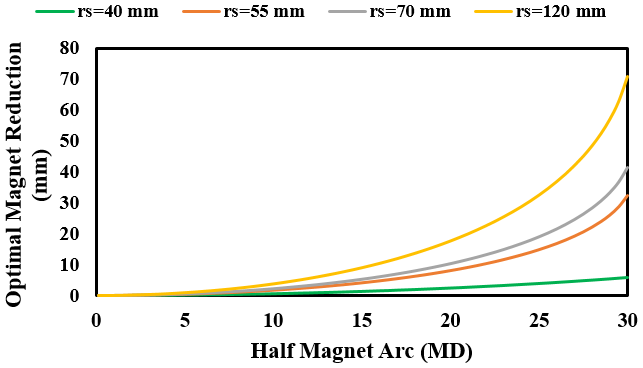
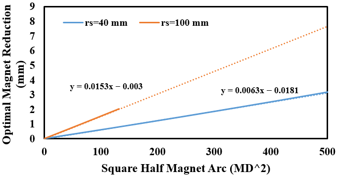
In this section, the results of the optimization using the bilinear mapping method are analyzed. Several motors with different dimensions and slot-pole combinations have been selected as case studies, and the optimal PM reduction has been determined in terms of the half-PM arc in mechanical degrees. Using relations (32) and (33), two acceptable roots are obtained for each design, as shown in Figure 5, Figure 6 and Figure 7. The second root, corresponding to motors with different stator inner radii, is presented in Figure 8. Further studies, as illustrated in Figure 9, show a linear relationship between the optimal PM reduction and the square of the half-PM arc.
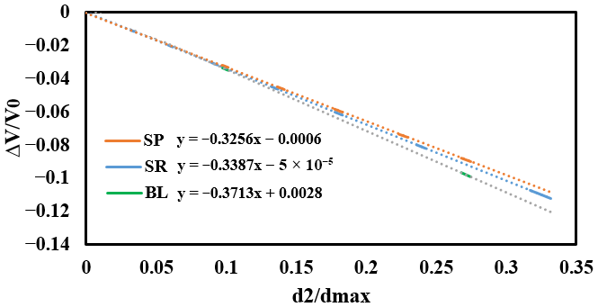
Figure 10 shows the PM volume reduction as a function of the PM reduction. This figure indicates a linear relationship between the PM volume reduction and the optimal PM reduction values.

7. Results

7.1. PM Reduction Formulation

The relationship between the optimal PM reduction d o p t and the half-pole angle θ p (in mechanical degrees) is calculated in quadratic parabolic form:
d o p t = α 4 θ p 2
Each motor has a unique value of α . When comparing different motors with varying rotor and stator sizes, the ratio of their α values equals the ratio of their pole radius ratio r m . Therefore, if the optimal PM reduction is known for a reference motor, the corresponding values for any other motor can be calculated using:
d o p t 2 d o p t 1 = α 2 α 1 = r m 2 r m 1
where the indices 1 and 2 correspond to the reference and studied motors, respectively. Consequently, it is only necessary to calculate the value of α for the reference motor once.
By examining the roots of the governing equations for determining PM reduction using the bilinear transformation method, it can be found that the equations obtained from the bilinear method yield two separate acceptable roots. The first root is zero, which indicates no reduction in the PM edge thickness.
Selecting the optimal PM reduction solution involves a trade-off between various motor performance factors. Studies indicate that the second root offers superior cogging torque reduction. On the other hand, the second root leads to increased efficiency. However, choosing the second root necessitates careful consideration of potential issues like demagnetization, manufacturing complexity, and the PM’s mechanical strength.
The first root ( d 1 = 0 ) is mathematically valid but physically trivial, representing the case of a concentric rotor with no PM modification. Its presence confirms that the original geometry is a solution to the system, but not the optimizing one.
The selection of the second root d 2 as the optimal solution necessitates consideration of practical constraints:
  • Demagnetization Risk: The reduction in PM edge thickness may lead to a higher local flux density under the thinnest part of the magnet during fault conditions (e.g., high stator currents). A subsequent local load-point analysis using Finite Element Analysis (FEA) is recommended to verify the magnet operates above its knee-point under worst-case scenarios;
  • Mechanical Integrity: For high-speed applications, the modified PM profile must be checked for mechanical stress, particularly at the thinnest edges. The use of a retaining sleeve or structural analysis is advised;
  • Manufacturability: The eccentric arc profile is well-suited for modern PM manufacturing processes such as sintering in shaped molds or molding of bonded magnets, and does not represent a significant fabrication challenge.
While d o p t can be calculated directly using (32) and (33). for varying θ values, it is recommended to use the optimal pole-width-to-pole-pitch ratio values derived in [37] from (35). to determine the optimal pole angle. Combining these approaches effectively minimizes both the amplitude and harmonics of cogging torque.
α p = N L N P k N L N P   w i t h   k = 1 , , N L N P 1
where N L   is least common multiple, and N P is the number of PM poles.

7.2. PM Material Utilization Formulation

Applying the eccentric PM pole optimization process leads to a proportional reduction in the PM’s volume. The percentage decrease in PM volume α V is directly related to the percentage reduction in PM thickness.
α V = V V 0 = V o p t V 0 V 0 = a d o p t d 0 + b
The ratio of the magnetic pole radii between two motors directly determines both the PM reduction ratio and the percentage volume reduction of one motor compared to the other. This relationship is expressed by
α V 2 α V 1 = r m 2 r m 1
Therefore, after calculating the optimal PM reduction, it is easy to determine the percentage of surface area reduction and consequently the volume and mass reduction of the PM compared to the initial design.

7.3. FEA Simulations and Analytical Model Extraction

7.3.1. Introduction

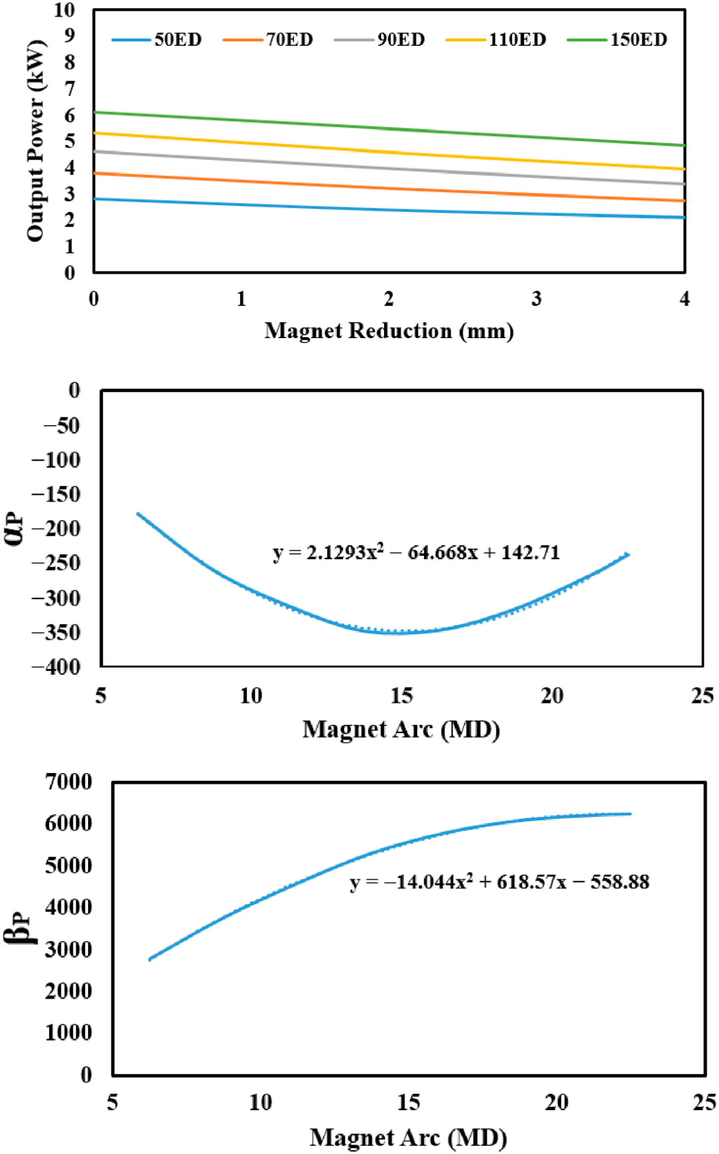
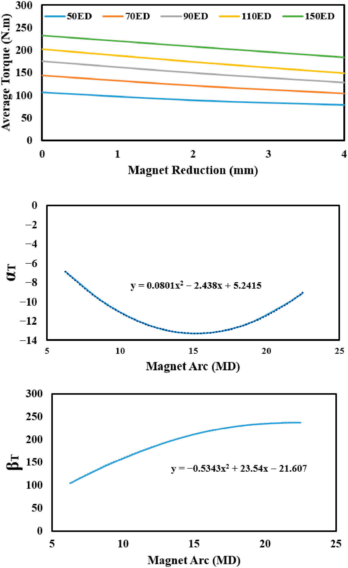
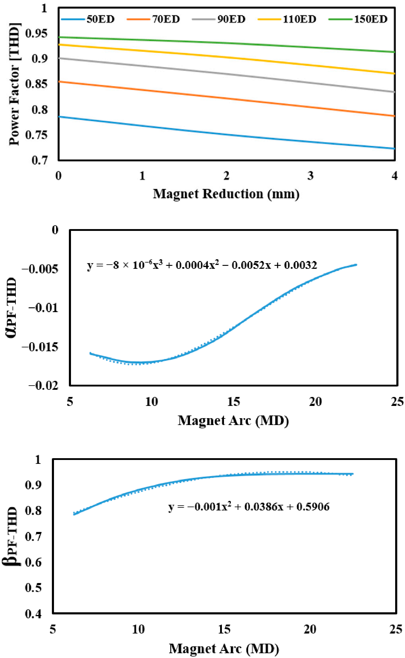
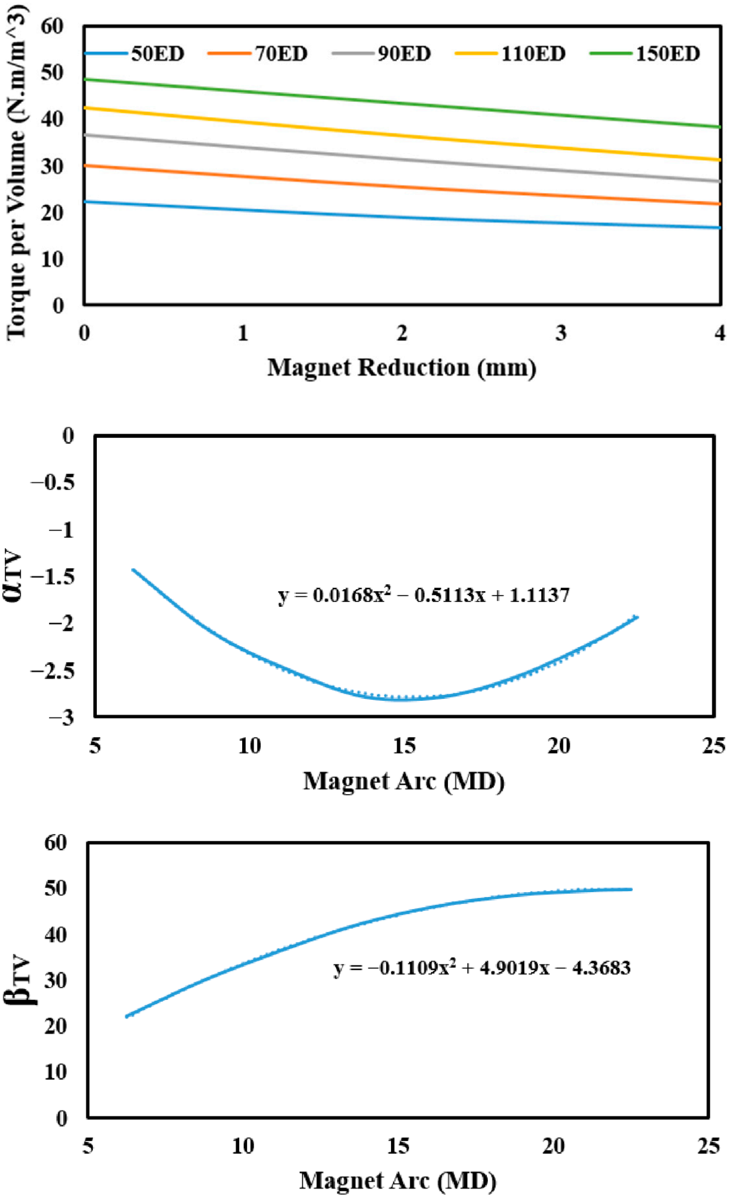
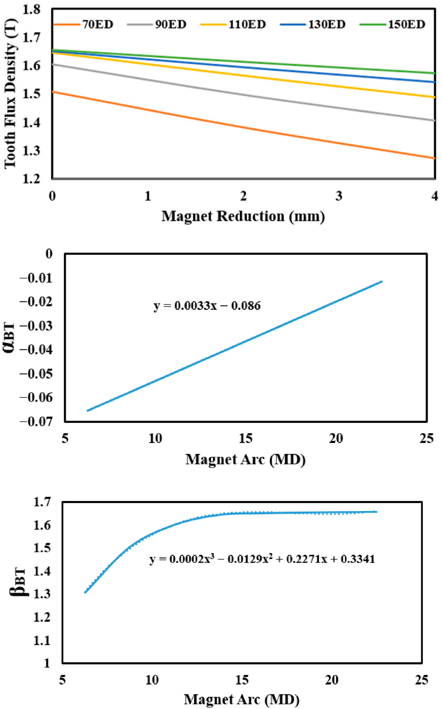
The impact of PM reduction on motor performance was formulated and validated through extensive 2-D FEA simulations. The results of this validation are presented in Figure 11, Figure 12, Figure 13, Figure 14, Figure 15, Figure 16, Figure 17, Figure 18, Figure 19, Figure 20, Figure 21, Figure 22, Figure 23 and Figure 24. Based on these FEA results, the analytical models are extracted.
The validation was performed using 2-D FEA in ANSYS Maxwell 2023 R1. Two solution types were used: (i) magnetostatic analysis for calculating no-load air-gap flux density and (ii) transient time-stepping analysis with a fixed time step corresponding to 0.1 mechanical degrees for cogging torque computation. The mesh was manually refined in the air-gap and PM regions, with a maximum element size of 0.5 mm, ensuring solution convergence. The material properties were defined as follows: the stator and rotor cores were modeled with non-linear B-H curves for M235-35A silicon steel; the PMs were defined as N35EH grade with a remanence flux density B r m = 1.21   T , a relative recoil permeability μ r m = 1.05 , and a demagnetization knee-point at H k = 900   kA / m at 100 °C.
The performance formulations presented in this section (e.g., for average torque, ripple) describe the outcome of applying the optimal PM reduction for cogging torque minimization. The shaped air-gap flux density inherently contains modified harmonic content. While not the primary goal, this incidental shaping can influence torque performance. For instance, the work in [32,33] demonstrates how deliberate harmonic injection shapes the torque profile. The analytical framework herein allows for the subsequent evaluation of such effects from the optimally cogging-minimized shape.
The influence of PM reduction d and the half-pole angle θ p  on key motor performance metrics can be expressed by the linear relationship M P = α · d + β where α and β are themselves quadratic functions of θ p . The fitted coefficients for the case study motor are consolidated in Table 1. The following subsections detail the implications of this formulation when evaluated at the optimal PM reduction d o p t . For metrics where coefficient ‘a’ is marked ‘-’, the term a · θ p 2 is not present in the expression for α.

7.3.2. Output Power Formulation

The output power is expressed by
P o u t = α P d + β P
with
α P = a α θ p 2 b α θ p + c α
β P = a β θ p 2 + b β θ p + c β
In optimum PM reduction, the output power can be written as
P o p t o p t = a ~ P θ p 4 b ~ P θ p 3 + c ~ P θ p 2 + d ~ P θ p + e ~ P
The output power variation is represented in Figure 11.

7.3.3. Average Torque Formulation

The average torque is expressed by
T a v g = α T d o p t + β T
with
α T = a θ p 2 b θ p + c
β T = a β θ p 2 + b β θ p + c β
In optimum PM reduction, the average torque can be written as
T a v g ( o p t ) = a ~ T θ p 4 b ~ T θ p 3 + c ~ T θ p 2 + d ~ T θ p + e ~ T
The average torque variation is represented in Figure 12.

7.3.4. Efficiency Formulation

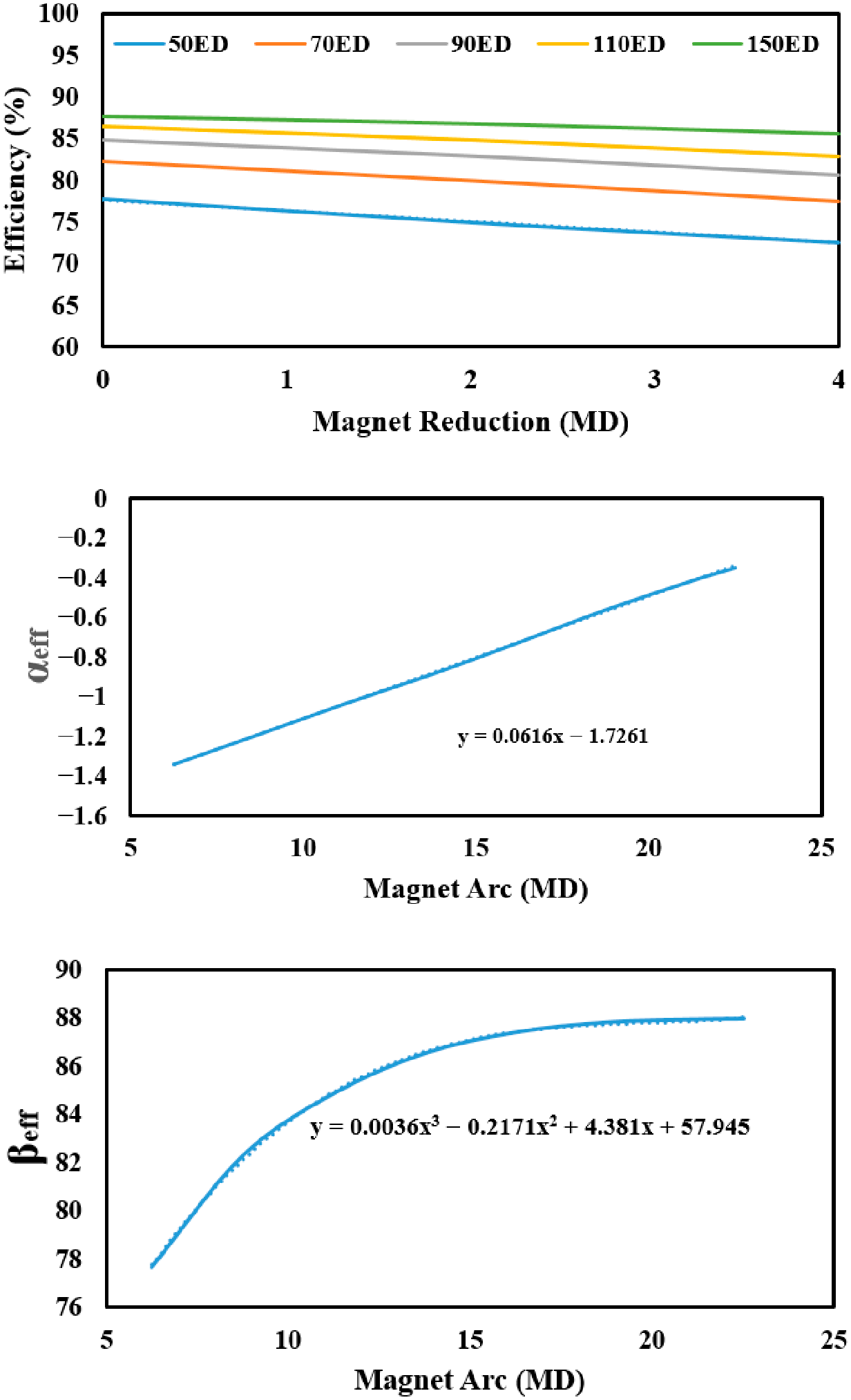
The efficiency is expressed by
η = α e f f d + β e f f
with
α e f f = a e f f θ p + b e f f
β e f f = c e f f θ p 3 + d e f f θ p 2 + e e f f θ p + f e f f
In optimum PM reduction, the efficiency can be written as
η o p t = a ~ e f f θ p 3 + b ~ e f f θ p 2 + d ~ e f f θ p + e ~ e f f
The efficiency variation is represented in Figure 13.

7.3.5. Mean Air-Gap Magnetic Flux Density

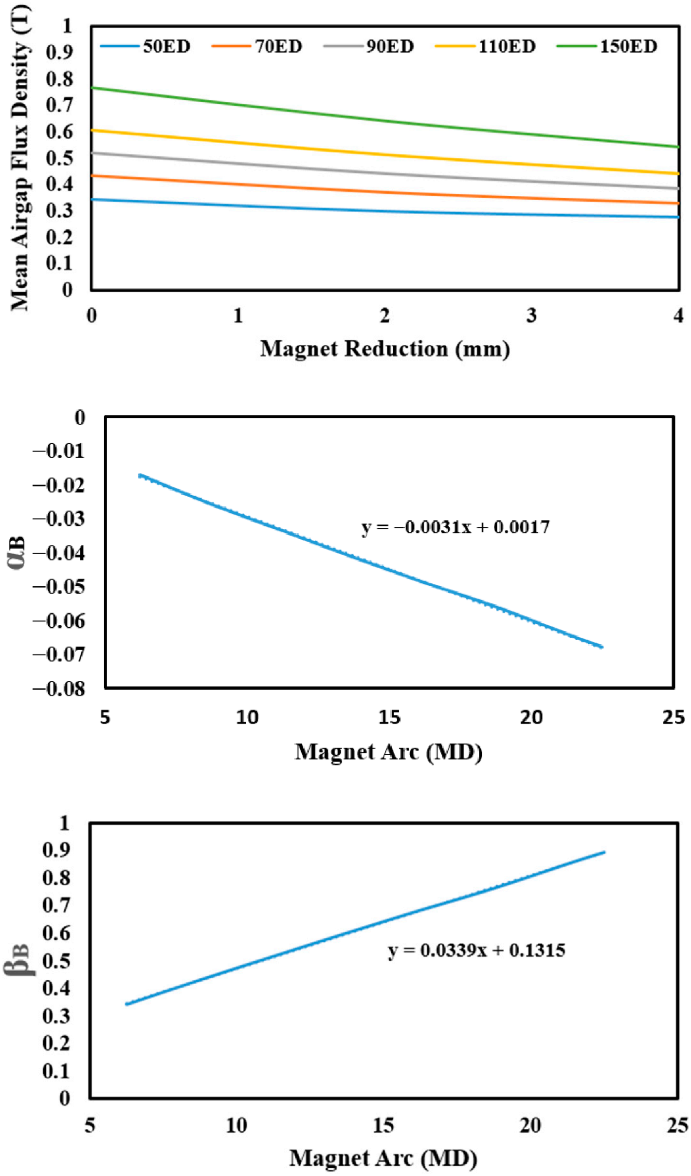
The mean of the magnetic flux density in the air-gap is expressed by
B m e a n = α B d + β B
with
α B = a B θ p + b B
β B = c B θ p + d B
In optimum PM reduction, the mean of the air-gap magnetic flux density can be written as
B m e a n ( o p t ) = a ~ B θ p 3 + b ~ B θ p 2 + c ~ B θ p + d ~ B
The variation of the mean air-gap flux density is represented in Figure 14.

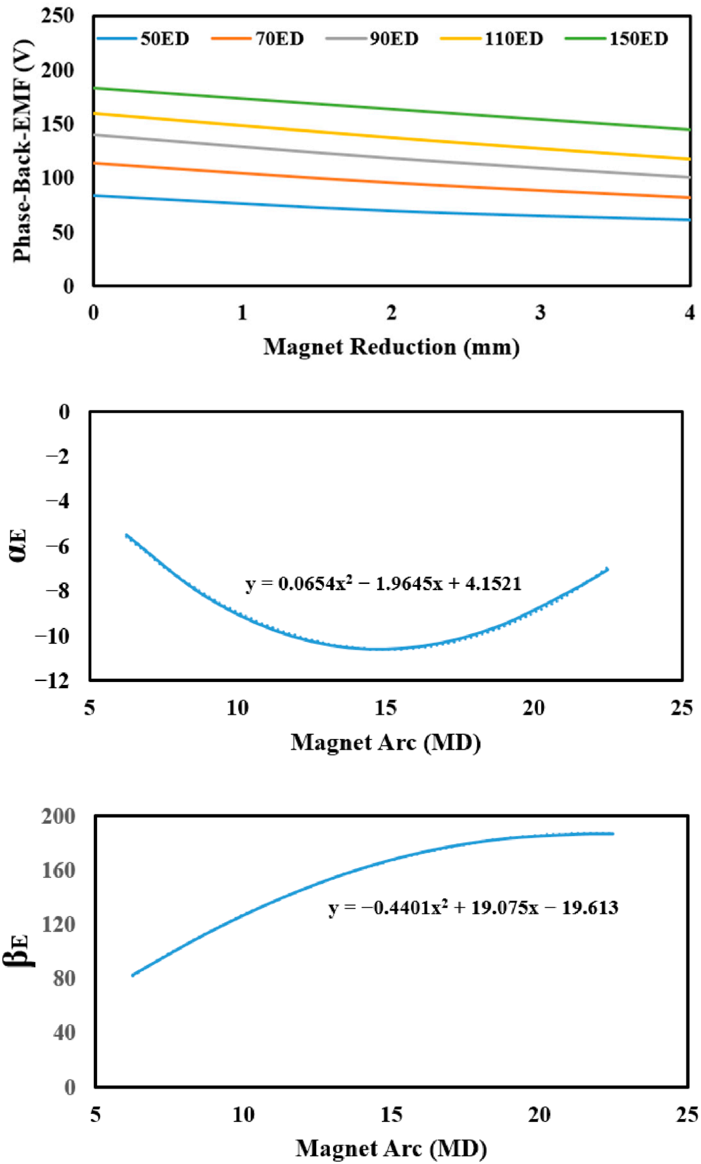
7.3.6. Phase-Peak of the Back-EMF

The phase-peak of the back-EMF is expressed by
E p e a k = α E d + β E
with
α E = a E θ p 2 b E θ p + c E
β E = d E θ p 2 + e E θ p + f E
In optimum PM reduction, the phase-peak of the back-EMF can be written as
E p e a k o p t = a ~ E θ p 4 b ~ E θ p 3 + c ~ E θ p 2 + d ~ E θ p + f ~ E
The phase-peak variation of the back-EMF is represented in Figure 15.

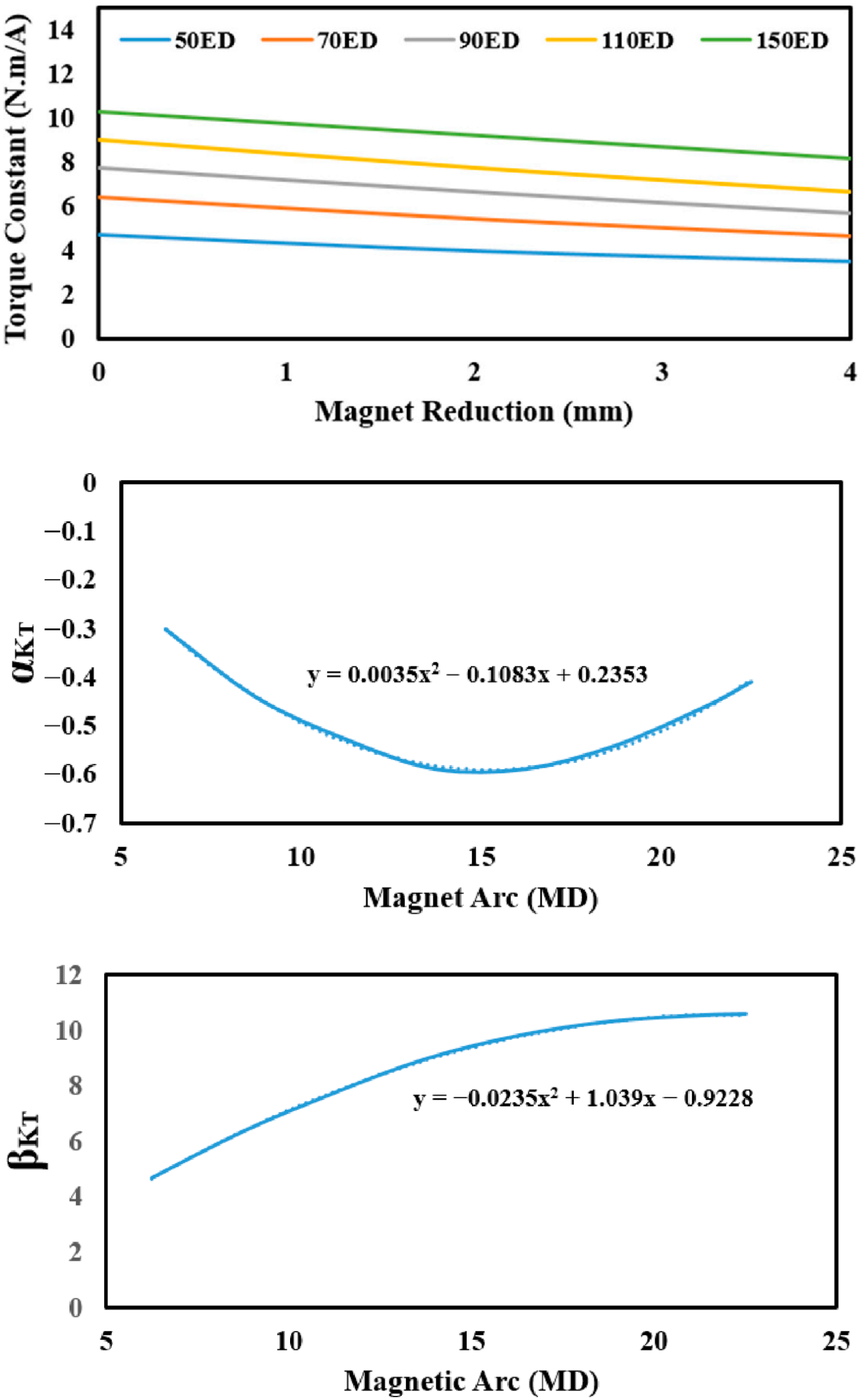
7.3.7. Torque Constant

The torque constant is expressed by
K T = α K T d + β K T
with
α K T = a K T θ p 2 b K T θ p + c K T
β K T = d K T θ p 2 + e K T θ p + f K T
In optimum PM reduction, the torque constant can be written as
K T o p t = a ~ K T θ p 4 + b ~ K T θ p 3 + c ~ K T θ p 2 + d ~ K T θ p + e ~ K T
The variation of the torque constant is represented in Figure 16.

7.3.8. Motor Constant

The motor constant is expressed by
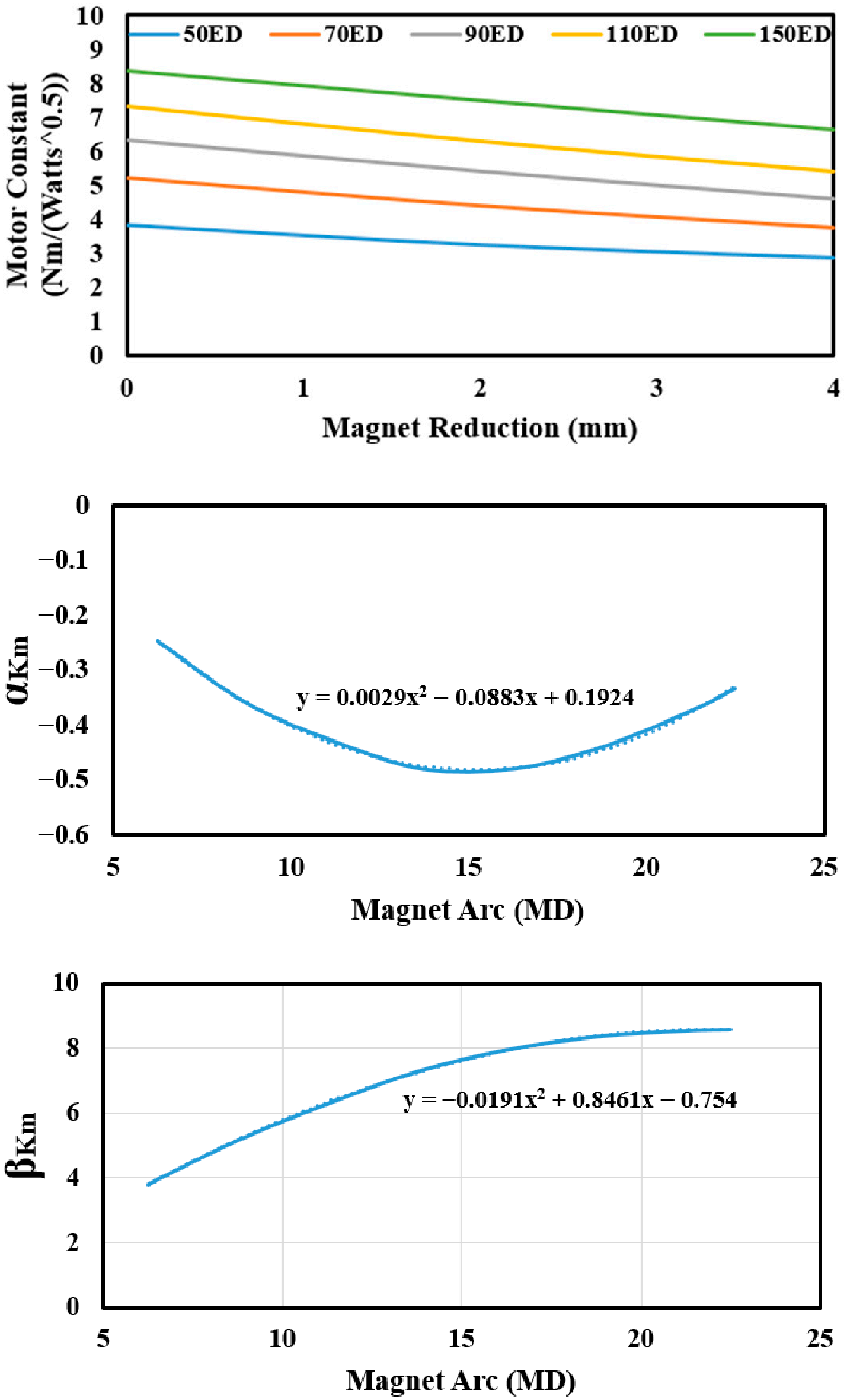
K m = α K m d + β K m
with
α K m = a K m θ p 2 b K m θ p + c K m
β K m = d K m θ p 2 + e K m θ p + f K m
In optimum PM reduction, the motor constant can be written as
K m o p t = a ~ K m θ p 4 + b ~ K m θ p 3 + c ~ K m θ p 2 + d ~ K m θ p + e ~ K m
The variation of the motor constant is represented in Figure 17.

7.3.9. Back-EMF Constant

The back-EMF constant is expressed by
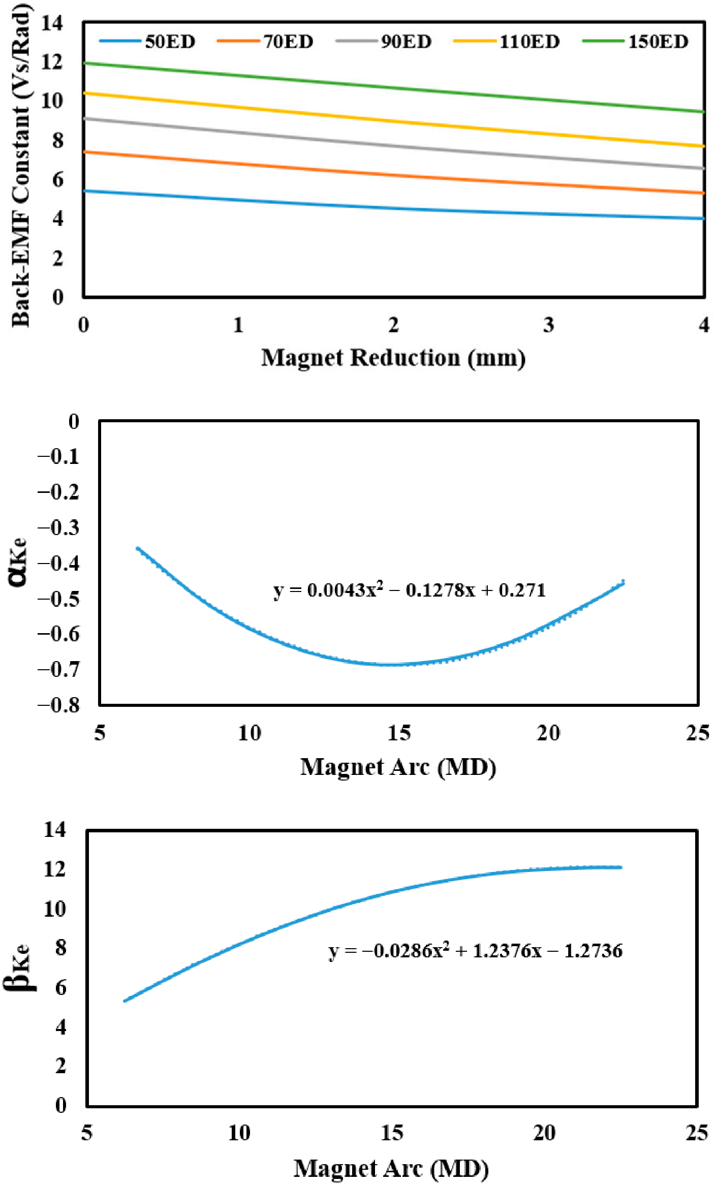
K e = α K e d + β K e
with
α K e = a K e θ p 2 b K e θ p + c K m
β K e = d K e θ p 2 + e K e θ p + f K e
In optimum PM reduction, the back-EMF constant can be written as
K e o p t = a ~ K e θ p 4 + b ~ K e θ p 3 + c ~ K e θ p 2 + d ~ K e θ p + e ~ K e
The variation of the back-EMF constant is represented in Figure 18.

7.3.10. No-Load Speed

The no-load speed is expressed by
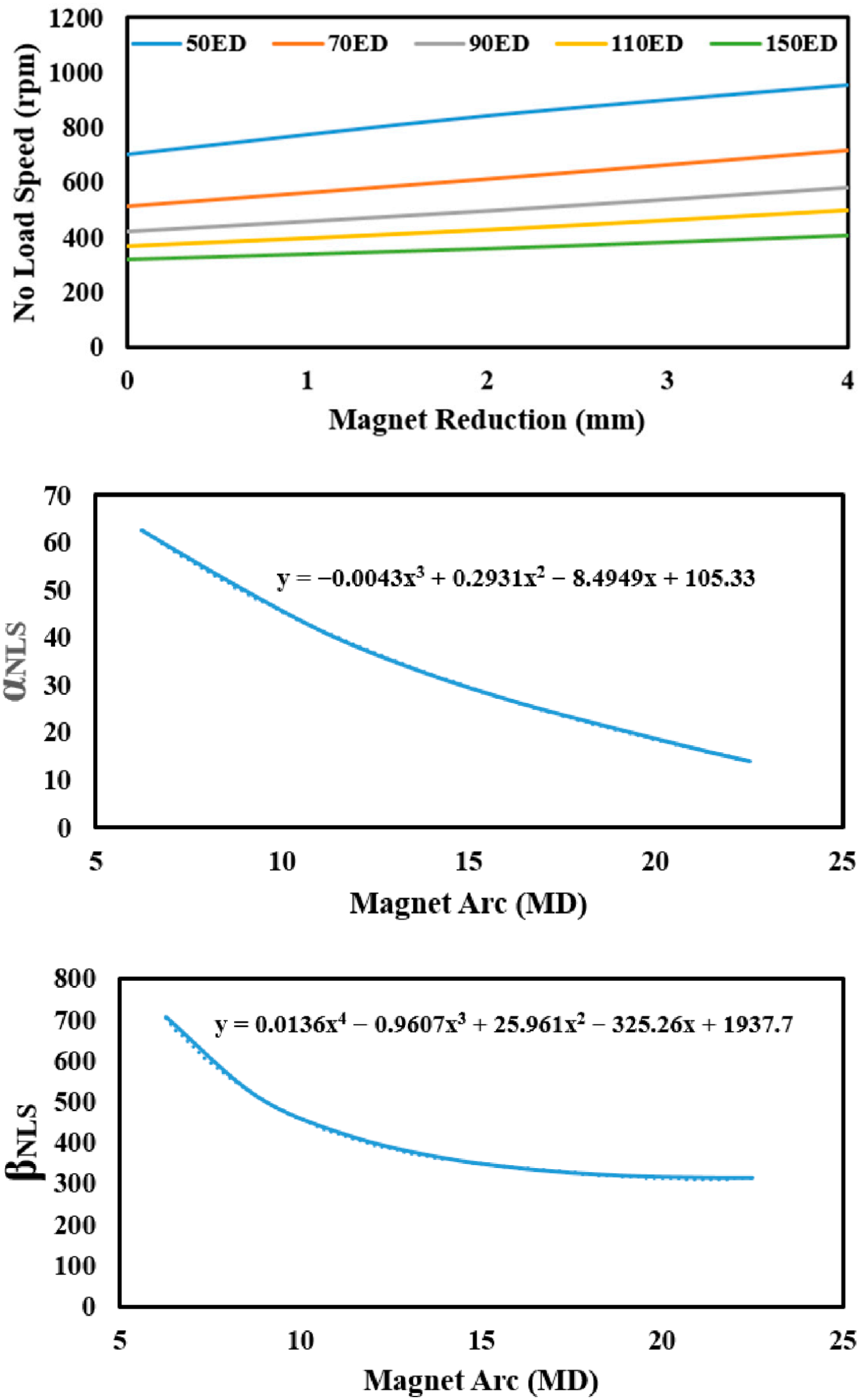
N N L = α N L d + β N L
with
α N L = a N L θ p 3 + b N L θ p 2 + c N L θ p + d N L
β N L = e N L θ p 4 + f N L θ p 3 + g N L θ p 2 + h N L θ p + i N L
In optimum PM reduction, the no-load speed can be written as
N N L o p t = a ~ N L θ p 5 + b ~ N L θ p 4 + c ~ N L θ p 3 + d ~ N L θ p 2 + e ~ N L θ p + f ~ N L
The no-load speed variation is represented in Figure 19.

7.3.11. Power Factor

The power factor is expressed by
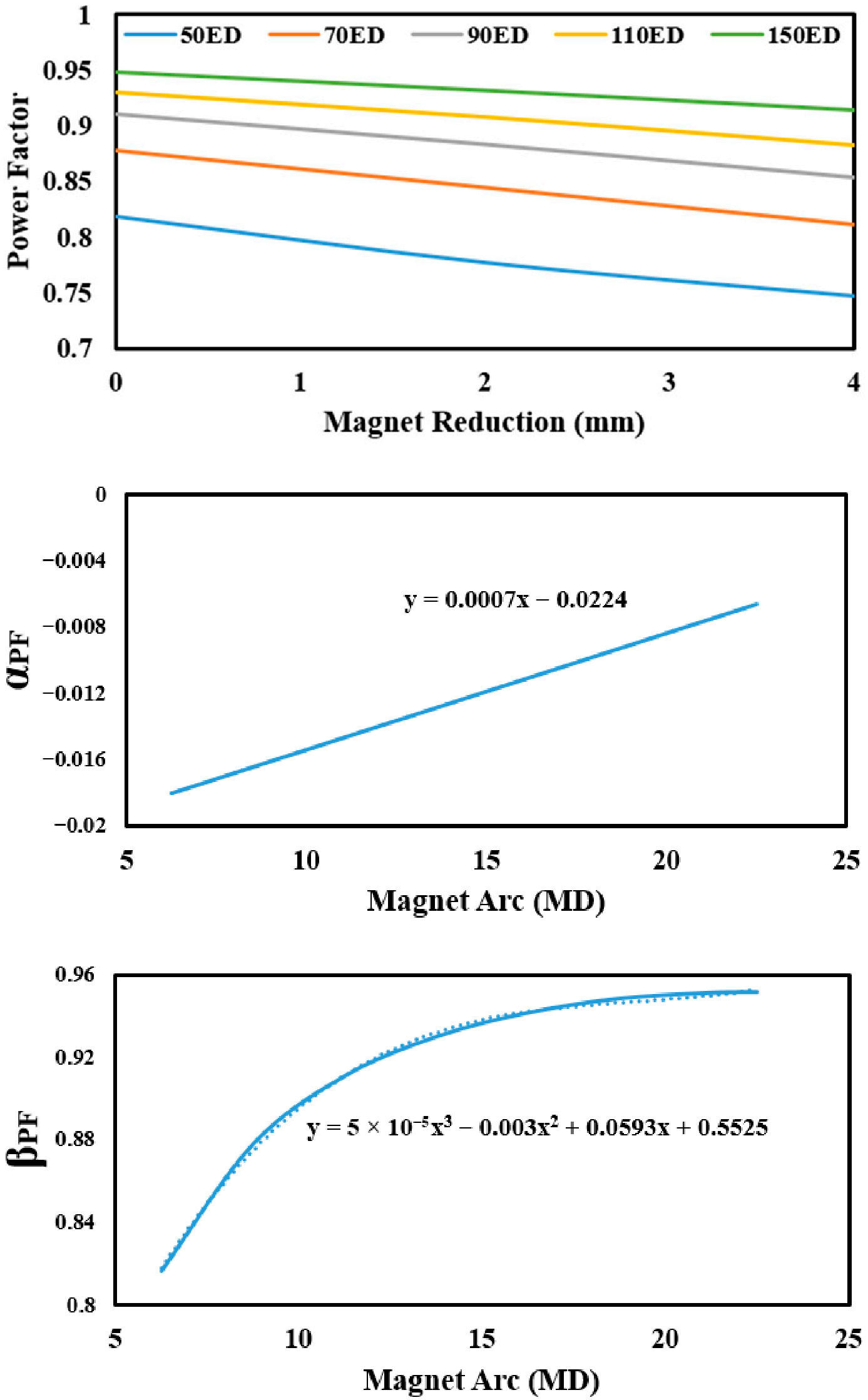
P F = α P F d + β P F
with
α P F = a P F θ p + b P F
β P F = c P F θ p 3 + d P F θ p 2 + e P F θ p + f P F
In optimum PM reduction, the power factor can be written as
P F o p t = a ~ P F θ p 3 + b ~ P F θ p 2 + c ~ P F θ p + d ~ P F
The power factor variation is represented in Figure 20.

7.3.12. Power Factor [THD]

The power factor [THD] is expressed by
P F T H D = α T H D d + β T H D
with
α T H D = a T H D θ p 3 + b T H D θ p 2 + c T H D θ p + d T H D
β T H D = e T H D θ p 2 + f T H D θ p + g T H D
In optimum PM reduction, the power factor [THD] can be written as
P F T H D o p t = a ~ T H D θ p 5 + b ~ T H D θ p 4 + c ~ T H D θ p 3 + d ~ T H D θ p 2 + e ~ T H D θ p + f ~ T H D
The variation of the power factor [THD] is represented in Figure 21.

7.3.13. Torque per Volume

The torque per volume is expressed by
T V = α T V d + β T V
with
α T V = a T V θ p 2 + b T V θ p + c T V
β T V = d T V θ p 2 + e T V θ p + f T V
In optimum PM reduction, the torque per volume can be written as
T V o p t = a ~ T V θ p 4 + b ~ T V θ p 3 + c ~ T V θ p 2 + d ~ T V θ p + e ~ T V
The variation of the torque per volume is represented in Figure 22.

7.3.14. Tooth Flux Density

The tooth magnetic flux density is expressed by
B T = α B T d + β B T
with
α B T = a B T θ p + b B T
β B T = c B T θ p 3 + d B T θ p 2 + e B T θ p + f B T
In optimum PM reduction, the tooth magnetic flux density can be written as
B T o p t = a ~ B T θ p 3 + b ~ B T θ p 2 + c ~ B T θ p + d ~ B T
The variation of the tooth magnetic flux density is represented in Figure 23.

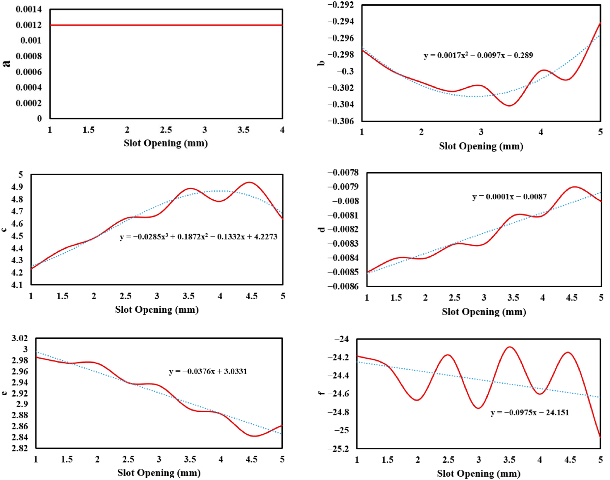
7.3.15. The PM Reduction Effect, PM Arc and Slot-Opening on the Motor Performances

The motor performances are expressed by
M P = α d + β
with
α = a θ p 2 + b θ p + c
β = d θ p 2 + e θ p + f
In optimum PM reduction, the motor performances can be written as
M P o p t = [ a 0 s + a 1 θ p 2 + b 0 s + b 1 θ p + c 0 s + c 1 ] d + ( d 0 s + d 1 ) θ p 2 + ( e 0 s + e 1 ) θ p + ( f 0 s + f 1 )
The coefficients variation of motor performances is represented in Figure 24.

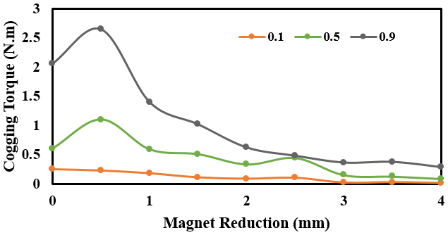
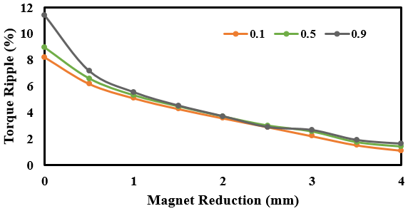
7.3.16. The PM Reduction Effect on the Cogging Torque and Torque Ripple in Eccentric Rotor Motor

As shown in Figure 25 and Figure 26, the PM reduction method significantly reduces cogging and torque ripple components in motors affected by rotor eccentricity. At the optimal PM reduction values, both cogging torque and torque ripple reach their minimum levels.

8. Discussion

The results show that:
  • Solving the equations obtained from the bilinear mapping gives two distinct roots;
  • To determine the values of the roots in other motors with different dimensions, there is no need to repeat the calculation process again. It is enough to have the optimal PM reduction for a motor with any dimensions as the reference motor and then calculate the optimal PM reduction values of the new motor by multiplying the ratio of the outer circle radius of the new motor to the radius of the reference motor circle;
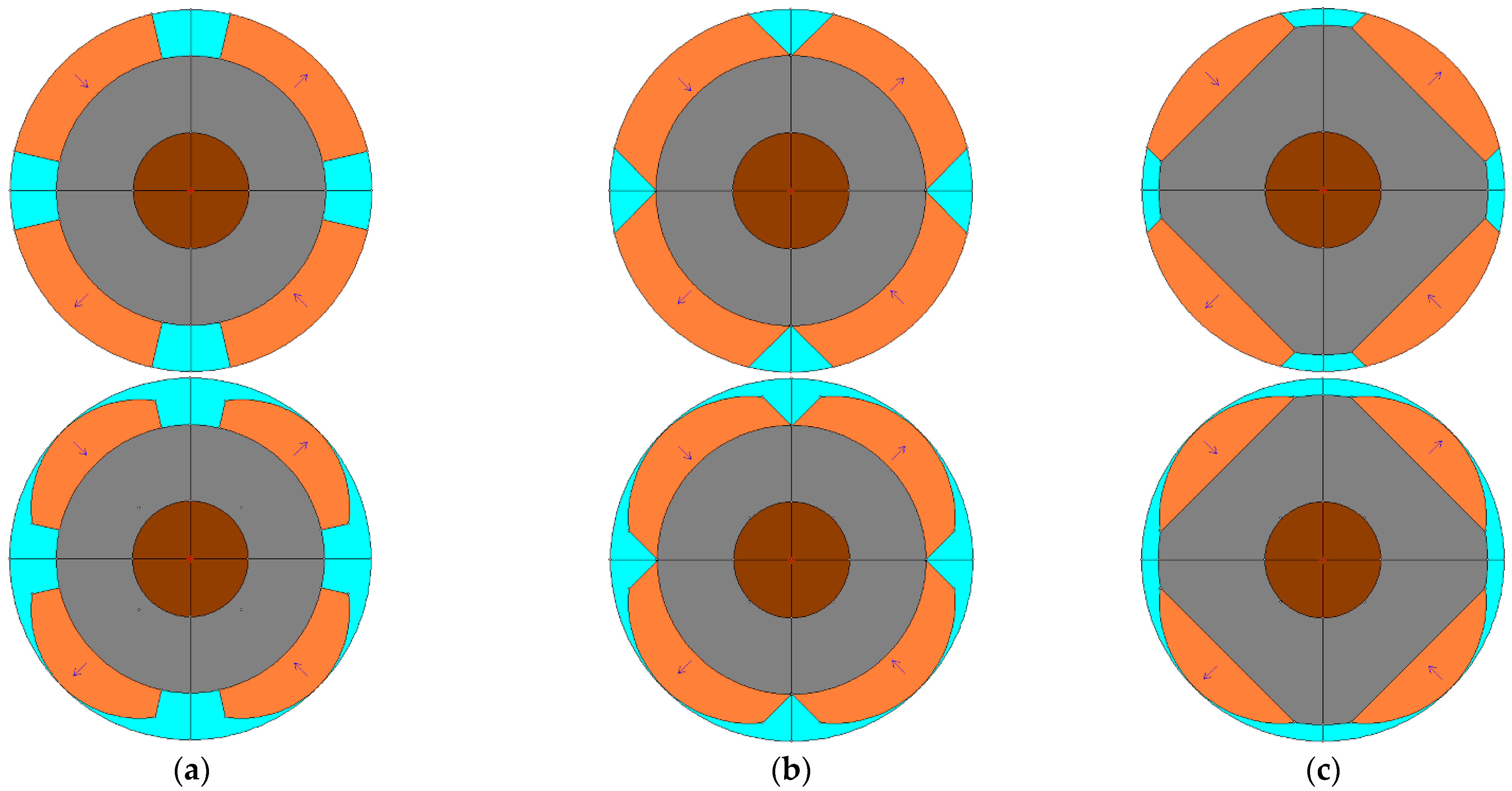
  • The optimal PM reduction values obtained from (32) and (33) are applicable to all types of SMPMM such as radial, parallel and bread loaf configurations, as illustrated Figure 27.
  • The quantitative impact of selecting the second root d 2 as the optimal PM reduction is significant. For the 45s-16p case study, a PM reduction of d 2 = 1.85   mm (approximately 15% of the central PM thickness) results in a reduction of the peak-to-peak cogging torque amplitude by over 60% compared to the baseline design ( d = 0 ), as predicted by the model and confirmed by FEA validation. Crucially, this substantial improvement in torque quality is achieved with only a minimal sacrifice in the main performance metrics: the average torque decreases by less than 2%, while the motor efficiency shows a net increase of approximately 0.5 percentage points due to reduced harmonic losses. This trade-off analysis confirms that the proposed optimal shape effectively targets and minimizes the slot-harmonic interactions responsible for cogging, without substantially affecting the fundamental wave energy conversion.
  • The analytical derivations in Section 7.3. assume linear magnetic material characteristics. This simplification allows for the elegant closed-form solutions central to the bilinear mapping method. The strong agreement between the analytically-predicted optimal geometry and the FEA validation results—which incorporate non-linear B-H curves for the core steel—demonstrates the robustness of the geometric solution. The optimal PM shape for cogging torque minimization appears largely independent of mild magnetic saturation effects in the stator teeth and yoke. However, this finding should be applied with caution. For final designs operating under high load conditions or those utilizing very high electrical loadings, the resultant magnetic saturation can alter the air-gap field distribution. Therefore, while the proposed method provides the optimal geometry, a post-optimal FEA under rated and fault conditions is essential to verify performance, check for local saturation hotspots, and conclusively assess the risk of partial demagnetization at the thinned PM edges.
  • A recognized limitation of the presented 2-D analytical model is that it does not explicitly account for three-dimensional (3-D) magnetic flux leakage, particularly the leakage between adjacent PM poles in the axial and circumferential directions. The model focuses on the dominant air-gap field interaction responsible for cogging torque. For a comprehensive performance prediction, especially regarding the accurate calculation of PM utilization factor, no-load losses, and behavior under high-load (high demagnetization risk) conditions, a 3-D FEA that captures these leakage paths is recommended as a subsequent verification step following the preliminary design established by this method.
  • The analysis of rotor eccentricity in Section 4 focused on static eccentricity. Dynamic eccentricity, where the rotor center revolves around the stator center, presents a more complex scenario as the eccentricity vector rotates with the rotor. Extending the bilinear mapping approach to handle this time-varying, rotating eccentricity condition represents a challenging but valuable direction for future research to comprehensively assess the robustness of the optimal PM shape under all practical fault conditions.
  • The physical significance of the second root d 2 stems from the nature of the bilinear transformation. This specific PM reduction, by creating an eccentric rotor contour, induces a counter-geometric effect via the mapping that precisely offsets the magnetic permeance variation caused by the stator slots in the equivalent transformed domain. In essence, it shapes the rotor so that, from the perspective of the fundamental slot-harmonic interaction modeled in (9)–(11), the stator appears nearly slotless (viz., b 14 0 ). Therefore, d 2 is the non-trivial solution that actively minimizes the energy variation due to slotting, leading to superior cogging torque suppression.
  • The practical implementation of the optimal shape must balance electromagnetic performance with the above constraints. The analytical method provides the target geometry, which should then be fine-tuned within feasible manufacturing tolerances and verified via comprehensive FEA for operational robustness.

9. Conclusions

This study presents a novel analytical methodology for optimizing the eccentric PM pole shape in SMPMMs in order to minimize cogging torque. The key contributions and findings are:
  • A novel bilinear mapping approach was developed to transform the slotted stator geometry into an equivalent slotless configuration. Solving the inverse mapping problem yields a direct analytical relationship between the stator slot geometry and the optimal PM edge reduction.
  • The governing equations inherently yield two mathematical solutions (roots). The first root corresponds to the trivial case of no PM modification. The second root provides the physically meaningful optimal PM reduction d o p t , which effectively minimizes slot-induced air-gap permeance variations that cause cogging torque.
  • The method exhibits exceptional scalability. Once d o p t is determined for a reference motor, the optimal value for a geometrically similar motor of different size can be obtained through simple scaling using the ratio of their outer PM radii r m 2 / r m 1 , thereby eliminating repetitive calculations.
  • Comprehensive performance formulations were derived, expressing key metrics (torque, efficiency, back-EMF, etc.) as explicit functions of the PM reduction. The analysis demonstrates that the optimal shape corresponding to the second root achieves a significant reduction in cogging torque (>60% in the case study), with a negligible impact on average torque (<2%) and a slight improvement in efficiency.
  • The effectiveness of the method was validated through FEA applied to a representative motor, confirming the predicted minimization of cogging torque. The proposed framework is general and applicable to various PM magnetization patterns (radial, parallel, bread-loaf).
  • Overall, the proposed approach provides motor designers with a powerful, fast and intuitive analytical tool for the preliminary design stage, enabling rapid identification of high-performance PM geometries with low-cogging.

Author Contributions

Conceptualization, A.J.; methodology, A.J.; validation, A.J. and F.D.; formal analysis, A.J. and F.D.; resources, A.J.; writing—original draft preparation, A.J.; writing—review and editing, F.D.; supervision, A.J.; project administration, A.J.; funding acquisition, A.J. and F.D. All authors have read and agreed to the published version of the manuscript.

Funding

This research received no external funding.

Data Availability Statement

The original contributions presented in this study are included in the article, further inquiries can be directed to the corresponding author.

Conflicts of Interest

The authors declare no conflicts of interest.

Abbreviations

The following abbreviations are used in this manuscript:
Roman Symbols
a,b,cCoefficients in performance equations
b 14 Stator slot-opening width [m]
B g Maximum air-gap flux density [T]
B r m Remanence flux density of PMs [T]
d PM reduction (edge thickness reduction) [m]
d o p t Optimal PM reduction [m]
D o u t Rotor outer diameter [m]
e Static eccentricity distance [m]
g Air-gap length [m]
H k Coercivity field of PMs [A/m]
k C Carter’s factor
l PM eccentricity ( where l = r m r e ) [m]
L i Stator stack length [m]
p Number of pole pairs
r e Radius of the outer rounded PM profile [m]
r m Radius of the outer profile of PM at the center of the pole [m]
r s Inner radius of the stator [m]
t 1 Stator slot-pitch [m]
T c Cogging torque [Nm]
T a v g Average torque [Nm]
Greek Symbols
α Constant related to slot - pitch ( where α = 2 π / t 1 ) [rad−1]
ε Relative eccentricity ( where ε = e / g )
θ p PM angular span (pole arc) [mech. degrees or rad]
μ 0 Permeability of free space [H/m]
μ r m Relative recoil permeability of PMs
Subscripts
optOptimal value
1,2Denote first and second root, or motor 1 and 2

References

  1. Chen, Z.; Xia, C.; Geng, Q.; Yan, Y. Modeling and analyzing of surface-mounted permanent-magnet synchronous machines with optimized magnetic pole shape. IEEE Trans. Magn. 2014, 50, 8102804. [Google Scholar] [CrossRef] [Scilit]
  2. Chen, Z.; Li, Z.; Ma, H.; Guo, Y. Optimization and analysis of permanent-magnet synchronous machine with eccentric magnetic pole shape. In Proceedings of the IEEE International Conference on Electrical Machines and Systems (ICEMS), Pattaya, Thailand, 25–28 October 2015. [Google Scholar] [CrossRef] [Scilit]
  3. Wu, L.; Zhu, Z.Q. Analytical modeling of surface-mounted pm machines accounting for magnet shaping and varied magnet property distribution. IEEE Trans. Magn. 2014, 50, 8101511. [Google Scholar] [CrossRef] [Scilit]
  4. Chai, F.; Liang, P.; Pei, Y.; Cheng, S. Magnet shape optimization of surface-mounted permanent-magnet motors to reduce harmonic iron losses. IEEE Trans. Magn. 2016, 52, 6301304. [Google Scholar] [CrossRef] [Scilit]
  5. Koo, M.-M.; Jang, S.-M.; Park, Y.-S.; Park, H.-I.; Choi, J.-Y. Characteristic analysis of direct-drive wind power generator considering permanent magnet shape and skew effects to reduce torque ripple based on analytical approach. IEEE Trans. Magn. 2013, 49, 3917–3920. [Google Scholar] [CrossRef] [Scilit]
  6. Zhou, Y.; Li, H.; Meng, G.; Zhou, S.; Cao, Q. Analytical calculation of magnetic field and cogging torque in surface-mounted permanent-magnet machines accounting for any eccentric rotor shape. IEEE Trans. Ind. Electron. 2015, 62, 3438–3446. [Google Scholar] [CrossRef] [Scilit]
  7. Li, Y.; Xing, J.; Wang, T.; Lu, Y. Programmable design of magnet shape for permanent-magnet synchronous motors with sinusoidal back EMF waveforms. IEEE Trans. Magn. 2008, 44, 2163–2167. [Google Scholar] [CrossRef] [Scilit]
  8. Lu, C.; Ferrari, S.; Pellegrino, G.; Bianchini, C.; Davoli, M. Parametric design method for SPM machines including rounded pm shape. In Proceedings of the IEEE Energy Conversion Congress and Exposition (ECCE), Cincinnati, OH, USA, 1–5 October 2017. [Google Scholar] [CrossRef] [Scilit]
  9. Pang, Y.; Zhu, Z.Q.; Feng, Z.J. Cogging torque in cost-effective surface-mounted permanent-magnet machines. IEEE Trans. Magn. 2011, 47, 2269–2276. [Google Scholar] [CrossRef] [Scilit]
  10. Laskaris, K.I.; Kladas, A.G. Permanent-magnet shape optimization effects on synchronous motor performance. IEEE Trans. Ind. Electron. 2011, 58, 3776–3783. [Google Scholar] [CrossRef] [Scilit]
  11. Zheng, P.; Zhao, J.; Han, J.; Wang, J.; Yao, Z.; Liu, R. Optimization of the magnetic pole shape of a permanent-magnet synchronous motor. IEEE Trans. Magn. 2007, 43, 2531–2533. [Google Scholar] [CrossRef] [Scilit]
  12. Kurfurst, J.; Duron, J.; Skalka, M.; Janda, M.; Ondrusek, C. Magnet shape optimization of brushless machine by self-organizing migrating algorithm. In Proceedings of the International Conference on Power Engineering, Energy and Electrical Drives (PEEED), Malaga, Spain, 11–13 May 2011. [Google Scholar] [CrossRef] [Scilit]
  13. Herlina; Setiabudy, R.; Rahardjo, A. Cogging torque reduction by modifying stator teeth and permanent magnet shape on a surface mounted PMSG. In Proceedings of the IEEE International Seminar on Intelligent Technology and Its Applications (ISITIA), Surabaya, Indonesia, 28–29 August 2017. [Google Scholar] [CrossRef] [Scilit]
  14. Lin, H.; Wang, D.; Liu, D.; Chen, J. Influence of magnet shape on torque behavior in surface-mounted permanent magnet motors. In Proceedings of the IEEE International Conference on Electrical Machines and Systems (ICEMS), Hangzhou, China, 22–25 October 2014. [Google Scholar] [CrossRef] [Scilit]
  15. Upadhayay, P.; Rajagopal, K.R. Torque ripple reduction using magnet pole shaping in a surface mounted permanent magnet BLDC motor. In Proceedings of the IEEE International Conference on Renewable Energy Research and Applications (ICRERA), Madrid, Spain, 20–23 October 2013. [Google Scholar] [CrossRef] [Scilit]
  16. Yang, Y.; Wang, X.; Zhu, C.; Huang, C. Reducing Cogging torque by adopting isodiametric permanent magnet. In Proceedings of the IEEE Conference on Industrial Electronics and Applications, Xi’an, China, 25–27 May 2009. [Google Scholar] [CrossRef] [Scilit]
  17. Mirahki, H.; Moallem, M.; Ebrahimi, M.; Fahimi, B. Asymmetrical magnet shape optimization based on S-C mapping for torque profile mitigation in unidirectional application of SPMS machine. IEEE Trans. Transp. Electrif. 2019, 5, 630–637. [Google Scholar] [CrossRef] [Scilit]
  18. Łukaniszyn, M.; JagieŁa, M.; Wróbel, R. Optimization of Permanent magnet shape for minimum cogging torque using a genetic algorithm. IEEE Trans. Magn. 2004, 40, 1228–1231. [Google Scholar] [CrossRef] [Scilit]
  19. Faradonbeh, V.Z.; Rahideh, A.; Ghahfarokhi, M.M.; Amiri, E.; Aliabad, A.D.; Markadeh, G.A. Analytical modeling of slotted, surface mounted permanent magnet synchronous motors with different rotor frames and magnet shapes. IEEE Trans. Magn. 2021, 57, 8100413. [Google Scholar] [CrossRef] [Scilit]
  20. Gao, L.; Cai, Z.; Liang, Y.; Wang, D.; Niu, Q.; Li, J. An Improved analytical model of magnetic field in surface-mounted permanent magnet synchronous motor with magnetic pole cutting. IEEE Access 2021, 9, 142804–142814. [Google Scholar] [CrossRef] [Scilit]
  21. Jang, S.-M.; Park, H.-I.; Choi, J.-Y.; Ko, K.-J.; Lee, S.-H. Magnet Pole shape design of permanent magnet machine for minimization of torque ripple based on electromagnetic field theory. IEEE Trans. Magn. 2011, 47, 3586–3589. [Google Scholar] [CrossRef] [Scilit]
  22. Yamazaki, K.; Kanou, Y. Shape optimization of rotating machines using time-stepping adaptive finite element method. IEEE Trans. Magn. 2010, 46, 3113–3116. [Google Scholar] [CrossRef] [Scilit]
  23. Yang, Y.-P.; Lai, G.-Y. Design of a permanent magnet motor with SPWM Shaped magnets for an electric scooter. In Proceedings of the IEEE International Symposium on Industrial Electronics (ISIE), Buzios, Brazil, 3–5 June 2015. [Google Scholar] [CrossRef] [Scilit]
  24. Scuiller, F. Study of a particular magnet shape for a five-phase surface-mounted PM machine. In Proceedings of the IEEE International Electric Machines & Drives Conferences (IEMDC), Chicago, IL, USA, 12–15 May 2013. [Google Scholar] [CrossRef] [Scilit]
  25. Pengfei, H.; Shuanbao, J.; Yingsan, W.; Nan, L.; Qinghu, Z.; Xingyu, W.; Hao, Z.; Fangxu, S. A Study of third-harmonic shaping in surface-mounted permanent magnet machine with bread-shape magnetic pole. In Proceedings of the IEEE International Conference on Electrical Machines and Systems (ICEMS), Harbin, China, 11–14 August 2019. [Google Scholar] [CrossRef] [Scilit]
  26. Zhu, Z.Q.; Wang, K.; Ombach, G. Optimal magnet shaping with third order harmonic for maximum torque in brushless AC machines. In Proceedings of the IET International Conference on Power Electronics, Machines and Drives (PEMD), Bristol, UK, 27–29 March 2012. [Google Scholar] [CrossRef] [Scilit]
  27. Wang, K.; Zhu, Z.Q.; Ombach, G. Torque enhancement of surface-mounted permanent magnet machine using third order-harmonic. IEEE Trans. Magn. 2014, 50, 8100210. [Google Scholar] [CrossRef] [Scilit]
  28. Li, Z.; Chen, J.-H.; Zhang, C.; Liu, L.; Wang, X. Cogging torque reduction in external-rotor permanent magnet torque motor based on different shape of magnet. In Proceedings of the IEEE International Conference on Cybernetics and intelligent Systems (CIS) and IEEE Conference on Robotics, Automation and Mechatronics (RAM), Ningbo, China, 19–21 November 2017. [Google Scholar] [CrossRef] [Scilit]
  29. Hong, H.; Yoo, J. Shape design of the surface mounted permanent magnet in a synchronous machine. IEEE Trans. Magn. 2011, 47, 2109–2117. [Google Scholar] [CrossRef] [Scilit]
  30. Chen, N.; Ho, S.L.; Fu, W.N. Optimization of permanent magnet surface shapes of electric motors for minimization of cogging torque using FEM. IEEE Trans. Magn. 2010, 46, 2478–2481. [Google Scholar] [CrossRef] [Scilit]
  31. Jabbari, A. An analytical expression for magnet shape optimization in surface-mounted permanent magnet machines. Math. Comput. Appl. 2018, 23, 57. [Google Scholar] [CrossRef] [Scilit]
  32. Ullah, W.; Khan, F.; Ullah, N.; Majid, A. Investigation of third harmonic utilization for torque performance improvement in novel H-type modular stator consequent pole machine. Electr. Eng. 2022, 104, 2703–2715. [Google Scholar] [CrossRef] [Scilit]
  33. Ullah, W.; Khan, F.; Sulaiman, E.; Umair, M. Torque characteristics of high torque density partitioned PM consequent pole flux switching machines with flux barriers. CES Trans. Electr. Mach. Syst. 2020, 4, 130–141. [Google Scholar] [CrossRef] [Scilit]
  34. Gieras, J.F. Analytical approach to cogging torque calculation of pm brushless motors. IEEE Trans. Ind. Appl. 2004, 40, 1310–1316. [Google Scholar] [CrossRef]
  35. Viorel, I.-A.; Hamemeyer, K.; Strete, L. On the Carter’s factor calculation for slotted electric machines. Adv. Electr. Comput. Eng. 2007, 7, 55–58. [Google Scholar] [CrossRef] [Scilit]
  36. Chen, J.-T.; Tsai, M.-H.; Liu, C.-S. Conformal mapping and bipolar coordinate for eccentric Laplace problems. Comput. Appl. Eng. Educ. 2009, 17, 314–322. [Google Scholar] [CrossRef] [Scilit]
  37. Snyder, W.-T.; Goldstein, G.A. An analysis of fully developed laminar flow in an eccentric annulus. AIChE J. 1965, 11, 462–467. [Google Scholar] [CrossRef] [Scilit]
Figure 1. Schematic cross-section defining the key design parameters (d, r e , r m ) for a generic surface-mounted PM motor (SMPMM) with eccentric PM poles. This illustrative diagram uses a 4-pole configuration for clarity; the analytical method is applicable to any pole number.
Symmetry 18 00368 g001
Figure 2. Considering three points (A, B and C) on the PM’s outer profile to write the outer circle equation.
Symmetry 18 00368 g002
Figure 3. Definition of stator slot-opening and slot-pitch.
Symmetry 18 00368 g003
Figure 4. Bilinear mapping from the eccentric region to concentric region: (a) z -plane; (b) w -plane.
Symmetry 18 00368 g004
Figure 5. Optimal PM reduction in 72s-20p PM motor ( r s = 107.5   mm , r m = 106.5   mm ). BP: bilinear method, d 1 : first root, d 2 : second root.
Symmetry 18 00368 g005
Figure 6. Optimal PM reduction in 45s-16p PM motor ( r s = 100   mm , r m = 99   mm ). BP: bilinear method, d 1 : first root, d 2 : second root.
Symmetry 18 00368 g006
Figure 7. Optimal PM reduction in 18s-4p PM motor ( r s = 40   mm , r m = 39   mm ). BP: bilinear method, d 1 : first root, d 2 : second root.
Symmetry 18 00368 g007
Figure 8. A comparison between optimal PM reduction ( d 2 : second root) for several motor sizes.
Symmetry 18 00368 g008
Figure 9. Linear relationship between the optimal PM reduction ( d o p t ) and the square of the half PM arc ( θ p 2 / 4 ) for the case study motors. The solid blue line represents the analytical trend from (35). for the 45s-16p motor. The red circle markers and green square markers denote the calculated optimal points ( d 2 ) for the 72s-20p and 18s-4p motors, respectively, demonstrating the scalability principle described by (36).
Symmetry 18 00368 g009
Figure 10. A linear relation between PM material reduction and the second PM reduction root. SP: surface parallel, SR: surface radial, BL: bread loaf (case study: 72s-20p motor).
Symmetry 18 00368 g010
Figure 11. Output power vs. PM reduction (case study: 45s-16p PM motor).
Symmetry 18 00368 g011
Figure 12. Average torque vs. PM reduction (case study: 45s-16p PM motor).
Symmetry 18 00368 g012
Figure 13. Efficiency vs. PM reduction (case study: 45s-16p PM motor).
Symmetry 18 00368 g013
Figure 14. Mean air-gap flux density vs. PM reduction (case study: 45s-16p PM motor).
Symmetry 18 00368 g014
Figure 15. Phase-peak of the back-EMF vs. PM reduction (case study: 45s-16p PM motor).
Symmetry 18 00368 g015
Figure 16. Torque constant vs. PM reduction (case study: 45s-16p PM motor).
Symmetry 18 00368 g016
Figure 17. Motor constant vs. PM reduction (case study: 45s-16p PM motor).
Symmetry 18 00368 g017
Figure 18. Back-EMF constant vs. PM reduction (case study: 45s-16p PM motor).
Symmetry 18 00368 g018
Figure 19. No-load speed vs. PM reduction (case study: 45s-16p PM motor).
Symmetry 18 00368 g019
Figure 20. Power factor vs. PM reduction (case study: 45s-16p PM motor).
Symmetry 18 00368 g020
Figure 21. Power factor [THD] vs. PM reduction (case study: 45s-16p PM motor).
Symmetry 18 00368 g021
Figure 22. Torque per volume vs. PM reduction (case study: 45s-16p PM motor).
Symmetry 18 00368 g022
Figure 23. Tooth magnetic flux density vs. PM reduction (case study: 45s-16p PM motor).
Symmetry 18 00368 g023
Figure 24. The coefficient (af) vs. slot-opening (case study: 45s-16p PM motor).
Symmetry 18 00368 g024
Figure 25. The PM reduction effect on the cogging torque in eccentric rotor motor (case study: 45s-16p PM motor).
Symmetry 18 00368 g025
Figure 26. The PM reduction effect on the torque ripple in eccentric rotor motor (case study: 45s-16p PM motor).
Symmetry 18 00368 g026
Figure 27. The coefficient a, b, c, d, e and f vs. slot-opening (case study: 4 pole PM motor): (a) Initial and optimal surface radial PM; (b) Initial and optimal surface parallel PM; (c) Initial and optimal surface bread loaf PM.
Symmetry 18 00368 g027
Table 1. Coefficients for the performance metric formulations M P = α · d + β MP where α = a · θ p 2 + b · θ p + c and β = d · θ p 2 + e · θ p + f . The coefficients are derived for the 45s-16p case study motor ( r s = 100   mm , r m = 99   mm ).
Performance Metric (MP)abcdef
Average torque , T a v g 2.12−64.66142.7−14.04618.5−558.8
Efficiency , η -0.0616−1.7261−0.21714.38157.945
Mean air - gap flux density , B m e a n -−0.00310.0017-0.03390.1315
Back - EMF phase peak , E p e a k 0.0654−1.96454.1521−0.446119.075−19.613
Torque constant , K T 0.0035−0.10830.2353−0.02351.039−0.9228
Motor constant , K m 0.0029−0.08830.1924−0.01910.8461−0.754
Disclaimer/Publisher’s Note: The statements, opinions and data contained in all publications are solely those of the individual author(s) and contributor(s) and not of MDPI and/or the editor(s). MDPI and/or the editor(s) disclaim responsibility for any injury to people or property resulting from any ideas, methods, instructions or products referred to in the content.