1. Introduction
Providing structured exercise and education to cardiac patients in an organized manner, determining medical risk reduction, means cardiac rehabilitation (CR). CR reduces mortality by up to 25%, increases functional capability, and reduces re-hospitalization, according to strong evidence [
1]. A proper rehabilitation program is required to enable cardiac patients to live independently and improve their quality of life (QoL) as they age [
2]. To increase joint range of motion (ROM), reinforce muscles, restore cardiac functional capabilities, and resolve deficiencies, most of these rehabilitation treatments require sessions of rehabilitation therapy [
3].
Integrating human and robotic-machine capabilities into a single system opens up a vast range of new possibilities for assistive technology development. Members of both the healthy and cardiac populations may benefit from its potential uses. Muscle strength is a limiting factor for many physical undertakings. Muscle weakness is also the leading cause of impairment in people with a range of cardiac diseases (e.g., those requiring open-heart surgery) or neuromuscular diseases [
4,
5]. Even after restoring strength and function to the upper limbs, many patients still have weight-bearing asymmetry. Long-term asymmetry can cause secondary muscle weakening in the upper limbs and even in the lower body [
5]. An asymmetry of 10% or more is regularly cited in the literature as an indicator of major injury risk [
4]. Humans have highly specialized and complicated “biological algorithms” for movement control that involve both higher and lower neural centers. These biological algorithms allow people to do extremely complex activities, like arm movement, while avoiding object collisions [
6]. Robotic manipulators, on the other hand, can be constructed to do jobs requiring significant forces or movements, depending on their structure and actuator power. However, the control algorithms that govern their dynamics lack the needed flexibility while maintaining the same level of quality as human limbs [
7].
As a result, it appears that integrating these two entities—the human and the robot—into a single integrated system controlled by a human could result in a solution that outweighs the disadvantages of each subsystem. When the machine’s mechanical power is combined with the innate human control system, it may be possible to perform activities that require higher forces than a human could otherwise produce. Two key scientific and technological concerns lie at the heart of this human–machine integration: (i) the exoskeleton (orthotic device) mechanism itself and its biomechanical integration with the human body, and (ii) the human–machine interface (HMI) [
8,
9].
As an assistive device, the exoskeleton is an external actuated structure with human-like joints and connections. The exoskeleton is worn by the patient, and its actuators produce torques that are applied to the human body segments. The human provides control signals for the exoskeleton, while the exoskeleton actuators provide much of the power required for task performance. Compared to the weight borne by the exoskeleton, the human becomes a component of the system and applies a scaled-down force.
The use of an exoskeleton in CR augmented with a VR system is a relatively recent technique aimed at allowing patients to interact with virtual items in virtual reality. As a result, the operator can interact with virtual objects [
10]. Developing such a mechatronic system suitable for CR requires comprehensive documentation, considering models of upper limb exoskeletons used for rehabilitation focused on mechanisms, actuators, sensors, and control techniques. A series of studies and research regarding the various existing upper limb robotic exoskeletons are highlighted in
Table 1.
By analyzing the solutions and prototypes of the upper limb robotic exoskeletons developed over time by various research groups and companies, as highlighted in
Table 1, the following conclusions can be drawn:
Actuator type: the actuator types can be DC servo, electro-hydraulic disk brakes; AC servo motor; stepper motor; BLDC motors; or cable system driven by BLDC motor, with harmonic or planetary gearboxes.
Control type/Feedback: the control type and feedback include incremental encoder; position and force sensors; EMG optical incr. encoder; electroencephalographic (EEG); and electrooculographic (EOG).
Movements: the parts of the body that the exoskeleton augments are shoulder–elbow, shoulder–elbow–wrist, or shoulder–elbow–wrist–hand.
DoFs: the degrees of freedom of the analyzed exoskeletons vary from 1 to 7, and they can be active or passive depending on the type of mechanism used.
Rehabilitation type: in terms of rehabilitation modalities, there are several approaches, such as active and/or passive assistance provided by the exoskeleton.
It has also been observed that there is very little evidence of clinical testing in the cardiac rehabilitation of existing exoskeletons, raising doubts about the already developed exoskeletons’ true efficiency and utility. In this context, in which there is an acute need for cardiac and COVID-19 rehabilitation, and, according to the World Health Organization, the fact that the number of people aged 65 and over will rise by 73% in developed countries and 207 percent globally by 2050 [
30], it is necessary to find new solutions to innovatively solve the acute shortage of rehabilitation specialists and increasing addressability of CR. This situation must be resolved, especially since this age group is at a higher risk of cardiovascular disease, and CR can help them improve their quality of life. This solution must come from the direction of the development of robotic exoskeletons for CR rehabilitation.
Following cardiac surgery, patients experience difficulties reaching an acceptable level of independence, even for simple physical activities [
31]. The rehabilitation process is long and painful, and often lacks challenges and fun, especially in an unfavorable context (e.g., depression or difficulty attending a rehab centre) [
32]. Many patients may thus lack the motivation for rehabilitation activities. Even in developed countries, the number of cardiac patients participating in rehabilitation activities is very low (e.g., 13 percent in Denmark) [
32].
Furthermore, the scientific literature increasingly reports the contribution of extrinsic motivation mechanisms (serious games/exergames) to rehabilitation effectiveness [
33]. Extrinsic motivation, via gamification, brings fun and joy to rehabilitation activities and diverts attention from inherent pain [
31].
Mobile networks and the internet can make up for the distance between patients and physiotherapists; thus, secondary rehabilitation stages can be performed by the patient at home, with remote monitoring. Motivation makes people do particular actions, giving specific reasons for these actions or needs. Thus, including motivation mechanisms in rehabilitation, both in the hospital/clinic and at home, can boost the number of patients performing complete rehabilitation.
Gamification (serious games) means inserting game mechanics into the non-game environment [
34]. It can increase user engagement, as people enjoy an interactive process full of fun, challenges, and competitive spirit, similar to games. Curiosity and excitement drive people to continue performing various tasks and to spend more time on the system they interact with. Technically, gamification leads to improving the KPIs of a process (rehabilitation, in our case) [
35]. These KPIs are important in defining the game rules and, more importantly, in communicating to patients what the rehab goals are.
In this paper, we present the design of a full upper limb robotic exoskeleton augmented by a virtual reality (VR) non-immersive module for the rehabilitation of patients following open-heart surgery or a major cardiac event. The proposed system provides rich sensory feedback that is similar to that of a natural and typical real-world experience, and it has been designed for scenarios including goal-directed activities such as games (e.g., virtual trainer, and picking up and placing different objects). To encourage the patient to conduct self-initiated and regulated motions, a virtual trainer assistance was introduced.
2. Materials and Methods
2.1. CardioVR-ReTone Design Overview
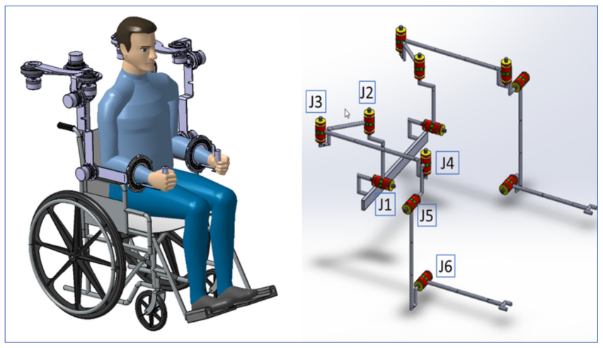
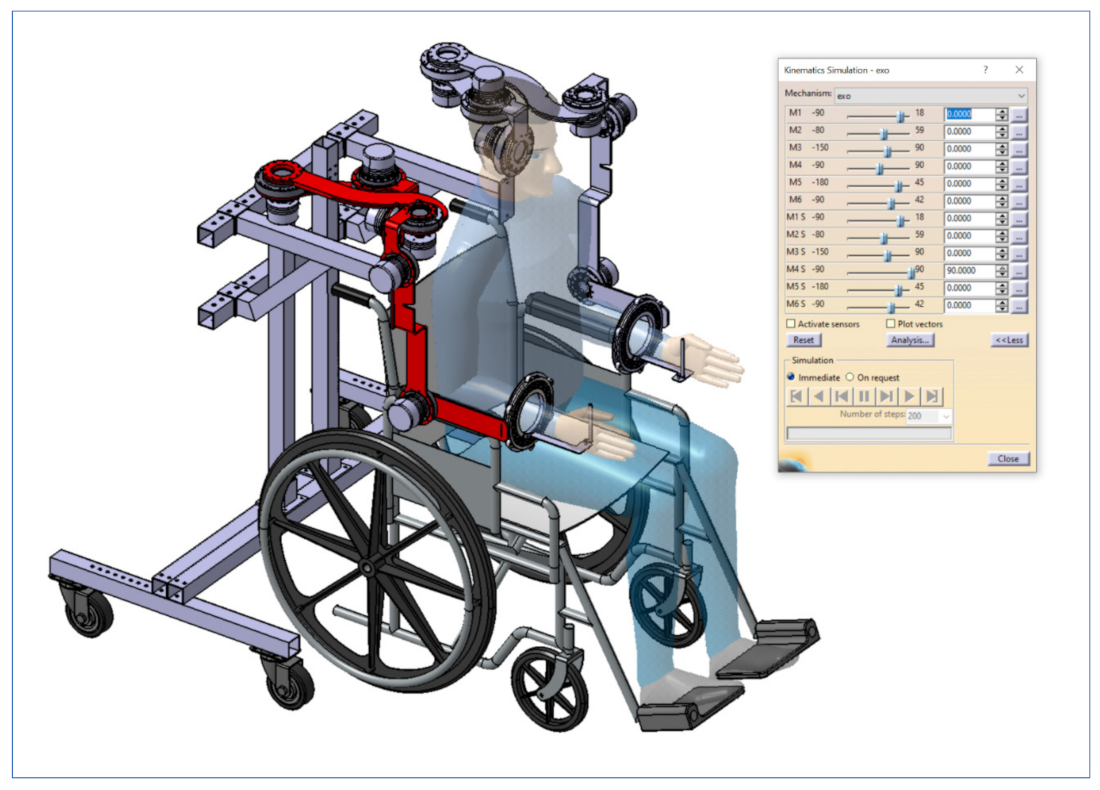
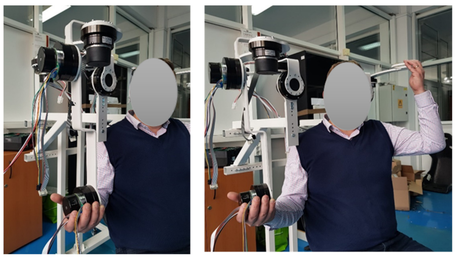
The CardioVR-ReTone robotic exoskeleton, designed in this paper, is presented in
Figure 1. The CardioVR-ReTone symmetric exoskeleton offers a total of twelve DoFs: six DoFs on each arm. The shoulder joint is represented by the first five motors, whereas the elbow joint is represented by the sixth motor. Being symmetric, the CardioVR-ReTone exoskeleton facilitates symmetric movements, which will have a beneficial effect on the functional upper extremities and reduce the injury risk.
The shoulder mechanism was designed as a rotational joint. The J1 rotation joint (
Figure 1) mimics shoulder raising and lowering mobility, while the triangle J2–J3–J4 mimics shoulder protraction and retraction mobility. The kinematic discrepancy that would be caused if only one rotation joint was employed for protraction and retraction on the back side of the shoulder is eliminated by arranging the joints in a triangle.
Two revolute joints positioned at 90° were used to create the forearm mechanism. This technique was chosen for the forearm mechanism in order to improve ROM while avoiding mechanical singularities and upper arm movement obstacles. Axis J5 is oriented to the axis
X, while joint J4, which is shared with the shoulder mechanism, is aligned to the vertical Cartesian axis (
Figure 1).
The elbow mechanism consists of two revolute joints, one of which is active and actuated by a motor (
Figure 1—joint J6) to allow for elbow flexion and extension.
The CardioVR-ReTone exoskeleton’s two robotic arms are attached on a height- and width-adjustable frame, allowing it to fit a wide range of patients’ sizes (
Figure 1).
The resultant CardioVR-ReTone is a simple, integrated, and morphologically compatible exoskeleton with mass and volume dispersed over the robotic exoskeleton framework. Abduction and adduction, flexion and extension, horizontal abduction and adduction, and internal and exterior rotation are some of the movements that the exoskeleton can assist and perform with the human upper torso and arms.
The movements of the CardioVR-ReTone system were designed to comply with a medical early CR protocol. The European Society of Cardiology (ESC) Guideline for CR [
36] recommends that upper-body training can begin when the chest is stable, i.e., usually after 6 weeks. In our protocol, we proposed to start the intervention earlier during hospitalization and to compare the results obtained after usual CR with those obtained using early CR assisted by a robotic device. We chose this type of protocol because there are studies that showed that early training after cardiac surgery is beneficial for the patient. We propose early CR based on the meta-analysis by [
37], which comprised the best studies available in the literature, and gave provisional substance to the general belief that aerobic exercise commenced early after cardiac surgery (during the first postoperative week) significantly improved functional and aerobic capacity, with a rate of adverse effects that was relatively low and not different to usual CR. The protocol of standardized exercises was refined by the medical team in collaboration with experienced kinetotherapists in accordance with the latest rehabilitation guidelines [
36] and international recommendations [
38]. The standardized protocol is available in the supplementary files of our group’s recent publication [
39].
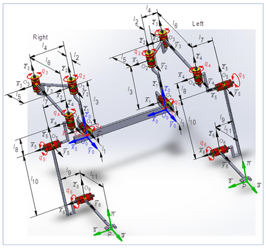
2.2. Forward Kinematics
The geometric and kinematic model for the CardioVR-ReTone exoskeleton was developed for the right arm. Further, using dedicated algorithms, the direct and inverse geometry and kinematics equations were determined for the CardioVR-ReTone exoskeleton—right arm 6R mechanical structure. The specific transfer matrix equation for a mechanical structure having rotational (
R) or translational (
T) motions, according to [
40], can be expressed using algorithms such as a matrix of locating algorithm. The obtained results are essential to the optimal design, dimensional aspect, and energy, but also to simulate the kinematic and dynamic behavior of the CardioVR-ReTone exoskeleton. This paper considers the terms “kinetic link” and “joint” to have the same meaning.
2.2.1. Geometrical Modeling of the CardioVR-ReTone Exoskeleton
The direct geometry equations (DGM equations) can be determined by applying the matrix of locating algorithm, considering the minimum number of geometric or mechanical restrictions. According to [
41], the situation matrices are defined as:
Similarly, for
, the locating matrices between the frames
and
are defined according to the following:
In expression (2), is a vector that defines the position of the last joint with a reference system attached to base of the robot, and characterizes the relative position of the system attached to the end effector beside the geometrical center of the last joint.
For
, the situating matrices between the two close related systems
are defined as:
According to [
41,
42], the rotation matrix between two neighboring reference frames is:
For
, the position vector between
and
with respect to
fixed frame, the position of joint
related to the same fixed frame is determined as:
The situation matrix between
is:
and for the end effector:
The orienting vector is defined [
41,
43] with the following identity:
The DGM equations are included in the following generalized matrix:
The direct geometrical modeling, regardless of the algorithm used, aims to establish the geometry equations that will serve in determining the direct kinematic model (DKM). According to the input data corresponding to DGM, the matrix of nominal geometry
for the 6R CardioVR-ReTone robot is presented in
Table 2.
Figure 2 highlights the kinematic scheme of the CardioVR-ReTone robotic exoskeleton. In keeping with
Table 1 and
Figure 2,
Table 3 highlights the geometrical particularities for the 6R CardioVR-ReTone robot.
For
, the situation matrices between frames
are:
which, in keeping with (8), according to (9), lead to:
representing the resulting orientation matrix and the position vector, between
frames, both being included in the expression of the column vector of operational variables (11).
According to [
41], in order to establish the orientation angles
for exact determination of the values, the trigonometric function
is used, defined by:
Hence, in keeping with (14), results in:
The column vector of operational coordinates, defined by (11), becomes:
The expression (15) characterizes the direct geometric modeling of the robot type 6R studied. The parameters included in (15) express the position and orientation of the end effector with respect to the fixed reference system, attached to the base of the robot.
2.2.2. Development of Kinematical Modeling for CardioVR-ReTone Exoskeleton
The operational kinematic parameters that express the movement of the end effector in Cartesian space will be discussed in this paragraph. To define these parameters, the iterative algorithm is used [
41]. This algorithm defines the kinematic parameters with respect to the fixed reference frame, attached to the base. The kinematic analysis considers the position and orientation of each link necessary to describe the location of the end effector in the robot workspace [
42,
44].
In applying the iterative algorithm [
41], in a first step, for the first joint J1 (
), it must be assumed that the absolute kinematic parameter values corresponding to the fixed base of the mechanical structure of the robot are:
For
, the angular and linear velocities that define the absolute motion of each kinetic link are determined using the expressions:
Similarly, for each
, the kinetic link of the robot, the corresponding angular and linear accelerations projected on the fixed reference system are defined as follows:
In the second part of the iterative algorithm, the kinematic parameters, which characterize the movement in each
kinetic link relative to the
mobile reference system, are determined as:
The expressions of angular and linear accelerations projected on the mobile reference system
, that characterize the relative movement of each
link, are defined by the following expressions:
In the last step of the iterative algorithm, the absolute motion of the final effector
is defined, considering the situation equations, respectively the absolute linear and angular velocities and accelerations (operating velocities and accelerations).
Taking into account the relations (24) and (25), the following is obtained:
The expressions previously determined are the direct kinematics equations (DKM) that characterize the absolute motion of the end effector, and will be used as input data in the dynamic modeling [
43] and representation of the equations of direct kinematics, that characterize the motion of the final effector (speed and acceleration) of the 6R robot in the Cartesian space, where in (26) and (27),
is the Jacobian matrix, as:
Based on the same algorithm, the kinematic control functions of the serial structure of type 6R are determined, as [
44]:
where
is the inverse of the Jacobian matrix.
Taking into account Equations (24) and (25), the operational speeds and accelerations can be expressed compared to the own system as:
and define the motion of the joint with respect to its own reference frame.
2.3. Actuators, Electrical, and Electronic Design
Exoskeleton movement is a delicate control procedure, especially in the subfield of human rehabilitation after open-heart surgery. Actuators are the prime movers in any mechanical system, and they are capable of transforming different types of energy into movement or force. This section discusses the identification of the actuators and sensorial systems used to generate motion in biomechanics and sensorial systems. Considering the developed kinematic model and mechanical design, we will calculate the requirements of the actuators and trigger the selection mechanism.
Several actuator types are used in upper limb exoskeletons: electric motors coupled with gearboxes; cables driven by electric motors; hydraulic cylinders; pneumatic muscles actuators (PMA); shape memory alloys (SMA); and series elastic actuators (SEA).
The development of a control system suitable for this type of application involves an analysis of actuator and sensorial systems used previously by fellow researchers.
As identified in the scientific literature, electric motors in combination with a gearbox, preferably a harmonic drive gearbox, are used the most often in exoskeletons. Feedback systems can be divided in two categories: human feedback systems and exoskeleton feedback systems.
Human feedback systems are used to predict human desired motions and use sensorial systems like surface electromyogram (sEMG), electroencephalogram (EEG), electrooculogram (EOG), electrocardiogram (ECG), muscle circumference sensors, inertial measurement unit (IMU), force sensors, and gesture detection by means of video analysis. sEMG are the most commonly used type of human sensorial system.
Exoskeleton feedback systems are used to ensure the correct control loop of the actuators and use sensorial systems like encoders for detecting the direction, speed, and position of a joint, torque control, potentiometers, joint angles, flexion sensors, pressure sensors, and vision tracking and VR systems. Most often, the exoskeleton feedback loop considers torque control and encoder feedback. VR systems have attracted attention due to their capacity to motivate human subjects.
After considering all of the actuator types, the BLDC electric motor coupled with harmonic drives was chosen due to its good torque-to-weight ratio, compact size, low backlash, and ease of control. Even though pneumatic muscles actuators (PMA) and shape memory alloy (SMA) have the great properties of reduced weight, there are major constraints related to the control techniques and team experience with such actuators compared to the control and integration of electric actuators. The characteristics of the harmonic drive complete electric actuator series, consisting of an EC60 flat BLDC Maxon motor, optical encoder, and HD gear, are presented in
Table 4.
Torque Requirements Calculation
Starting from the kinematic model highlighted in this article, and taking into consideration the information regarding the properties of the exoskeleton segments, as well as the anthropomorphic characteristics of the upper limb body segments for Romanian male subjects and actuator features, we then moved on to the selection of electric motors.
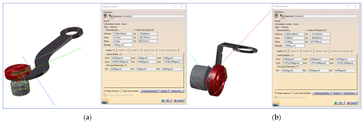
Table 5 presents an overview of the mechanical properties of exoskeleton links as obtained from the design phase using the Catia
© 3D modeling software. Every link connects two exoskeleton joints, as mentioned in the subscript. Joints J2 and J3 are interconnected by link L
2,3.
Table 6 presents an overview of the upper limb anthropomorphic characteristics of Romanian male subjects, and defines a relation between the exoskeleton joints that have to sustain the load introduced by a specific body segment.
The actuator selection considers calculating the torque required by a specific joint to maintain equilibrium with the rest of kinematic chain, including previously selected actuators and associated human body segments. It was calculated using the following formula (33):
where
j is the joint for which torque is calculated,
Tjexo (34) represents the torque required by a specific exoskeleton joint to maintain equilibrium with the associated exoskeleton segment,
Tjbody (34) represents the torque required by a specific exoskeleton joint to maintain equilibrium with the associated human body segments, and
Ks is an oversize safety coefficient.
where,
= length of the link between exoskeleton j and j + 1
= distance from the starting point of the link up to link j center of gravity
= gravity force acting on a link j
= diameter of actuator that drives joint j
= center of gravity of the actuator driving joint j
= gravity force acting on actuator
j
= length of the human body segment j
= represents the joint group number associated with the movement of the body segment.
The actuator selection started from joint J6 to joint J1. This approach is required as the actuators selected for a joint will involve additional torque requirements for the actuator selection process of previous joints.
Table 7 presents an overview of the torque and safety coefficient estimation, together with the actuator selection for every exoskeleton joint.
As can be observed in
Table 7, with the exception of joints J1 and J2, all joint torque requirements are smaller than the average torque produced by the selected actuator. This means that the actuator has enough torque to control the exoskeleton and the attached body segments. Joint 4 is close to the average torque, but low under repeated peak torque value.
The torque requirement for joints J1 and J2 is greater than the average torque, but still under the repeated peak torque value. Even though a CPU-32 actuator would have been a more reliable option, its dimensions and weight together with financial factors constrained the selection process for CPU-25.
After the actuators were selected, identifying the right actuator motor controller was required in order to meet the technical and application requirements. For this application, every actuator motor was controlled by a Maxon EPOS4 5/50 controller with a CANopen fieldbus interface. The EPOS4 5/50 controller can provide speed control, position control, and torque control loops. On top of these control features, the EPOS4 controller can be easily integrated within high programming languages or other PC-based software with the help of several plug-ins provided by the manufacturer.
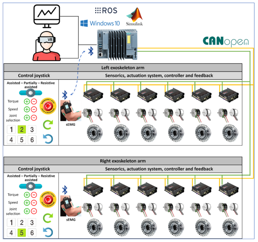
2.4. Control Architecture Design
The control architecture for the CardioVR-ReTone exoskeleton, presented in
Figure 3, consists of several important components: virtual reality, a Simulink environment, a main control unit, an exoskeleton actuation system, an exoskeleton control joystick, and sensorics. The virtual reality component consists of an application that will immerse the subject within a virtual environment to enhance the rehabilitation experience by triggering motivational mechanisms.
Simulink is the environment where kinematic equations are solved and the exoskeleton joint coordinates, speed, and torque are calculated, taking into consideration the selected exoskeleton operation and commands triggered by means of an exoskeleton joystick.
The main control unit is a fail-safe open controller developed by Siemens that combines the functionalities of programmable logic controllers with a PC-based platform preinstalled with Windows 10 IoT Enterprise. The Simatic ODK 1500 software controller that runs on the hardware of the open controller can provide a seamless integration and connectivity of high-end programming languages with open controller hardware resources. Therefore, the virtual reality, robot operating systems (ROS), and Simulink software are installed and executed on the open controller. The data received from Simulink are sent to the open controller hardware and delivered to every exoskeleton joint actuator controller using a CANopen communication module.
The exoskeleton actuation system is built out of several subcomponents: the HD gear, the motor, the Hall sensors and encoder, and the digital position controller EPOS4. The EPOS4 controller drives the exoskeleton joint, considering the motion parameters calculated by Simulink and delivered by the main control unit via the communication protocol to each EPOS4 controller. The EPOS4 controllers are enhanced with a safe torque off (SFO) functionality, which is triggered by pressing the emergency button on the joystick. The SFO turns off the power on the controller output to prevent the motor from producing torque. The EPOS controller uses the optical encoder and Hall sensors within the positioning and speed control loops. The torque control loop considers the current injected into the motor’s windings.
Sensorics components are the surface EMG electrodes placed on the human body that can identify the subject’s muscle activity. The muscle activity values are fed into the Simulink algorithm using Bluetooth, calculating how much torque the actuators need to compensate for to reach the desired position within the rehabilitation exercise.
An exoskeleton control joystick is used for operating mode selections. Three operating modes are considered for development: assisted, partially assisted, and resistive. Assisted mode is the operating mode in which the exoskeleton actuating systems move the subject’s arms using the exoskeleton structure without any major effort for the operator, according to the motion parameters generated by Simulink with respect to the rehabilitation exercise selected. The partially assisted mode is an operating mode whereby the EMG sensors’ feedback is considered by the Simulink algorithm, and only a specific amount of torque is generated by the motors to compensate for the subject’s actions towards reaching the desired position. The resistive mode is the operating mode in which the exoskeleton actuating system opposes the subject’s actions in order increase the subject’s effort towards achieving a specific action. In every operating mode, the patient can use the joystick buttons to increase or decrease the operating speed and torque delivered by the exoskeleton actuating system during their rehabilitation exercises. In addition, by means of the joystick buttons, the subject or the medical staff can select a specific exoskeleton joint and move it forwards or backwards in order to customize the subject’s rehabilitation exercises and fit the exercises to the user’s actual body condition.
In terms of safety features, the exoskeleton actuation system can be powered only if the emergency stop buttons are not pressed. Emergency stop buttons are mounted on every exoskeleton arm, and a third emergency button is mounted on the base frame of the exoskeleton. The emergency stop buttons will trigger the SFO functionality. Another safety feature that turns the actuators on/off is the dead-man switch, not represented in
Figure 3. The exoskeleton system only follows the motion controls provided by Simulink when the dead-man switch is placed in an intermediary position. If the dead-man switch is released or pressed too hard, the actuators stop.
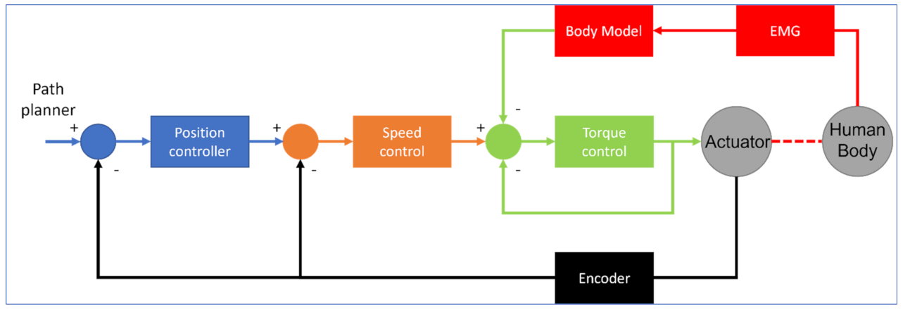
The exoskeleton control loop (see
Figure 4) is based on a three-level cascade PI(D) loop, which is a common practice in most of the control systems involving motion control. The main control loop receives the position, velocity, and acceleration from the path planner, controls the position of the joint actuator, and provides motor velocity and acceleration as outputs. The inner loop controls the actuator velocity and outputs the current reference for the innermost control loop. The encoder mounter on the BLDC motor feeds information for the speed and position control loops.
Within the current control loop or torque control loop, since torque is directly proportional to the current through the motor windings multiplied by the motor constant, partial torque is delivered to achieve the desired position with a desired speed. In the partially assisted operating mode of the exoskeleton, the control loop is completed with a torque estimation of human muscle based on a body model which is fed with EMG signals.
The VR motivational application requires process information from the main control unit to detect if the subject is following the rehabilitation exercise pattern, and to identify any error between the actual versus the desired arm position in order to adjust the motivational exercise intensity. Such process information can be related to exoskeleton TCP which includes coordinates on X, Y and Z and orientation angles. Calculating exoskeleton TCP is based on feeding information gathered from the motor encoders to the direct kinematic model that runs on Simulink. An ROS node, that makes use of the MODBUS TCP fieldbus (modbus_plc_siemens), cyclically reads exoskeleton TCP from the main control unit and feeds the data to an ROS node that manages subject movements to detect whether the arm is moved according to the rehabilitation exercise.
2.5. Patient Extrinsic Motivation with VR
2.5.1. Operating and Control Application: Interaction Scenarios
To design the interaction between the patient and the exoskeleton-based rehabilitation system, we built interaction scenarios that cover the entire rehabilitation process lifecycle (starting immediately after the surgery, continuing at the patient’s home, and ending once the patient is completely recovered). The first rehabilitation stage covered by the interaction scenarios begins with the first movements the patient has to make, after the surgery. The patient will be (fully) supported by the exoskeleton in performing these movements, based on physical exercise templates established by the therapist. In the second rehab stage, the patient performs the movements being assisted by the exoskeleton (e.g., they will need to put in some effort, just being helped by the exoskeleton). The CardioVR system will check the movement “correctness” (how “far” the movements are, compared to the movement template set by the therapist). The third stage is after discharge, when the patient performs exercises without any support and only being monitored by sensors (Android wrist bands and/or a Kinect sensor).
The motivation (gamification) mechanism we used in the CardioVR software platform is the patient’s rehabilitation journey, comprising a series of levels to be carried out (steps of recovering mobility) up to complete rehabilitation. These levels are decided by a rehab mentor (e.g., the therapist), who will set up the patient’s journey and will assist them throughout.
The patient will follow the rehab journey, which will be managed by the software platform. The patient will be shown the steps to take, their current physical state, the short-term mobility goals, current level challenges (why the patient has to do it and why it may be difficult), and also interactive lessons on cardiac disease, post-surgery rehab, healthy lifestyle (e.g., “what to know to avoid future health issues”). This will be done via a VR game (immersed or not, depending on the patient’s age and potential aversion to “unknown” technology). The patient will receive the challenges in stages, according to their rehab progress. A level consists of a series of physical exercise sets to be performed. For each level, the “software” mentor in the VR game will explain the exercises and the challenge. Regardless of the rehab level, there are three user roles (patient, therapist, therapist assistant) and two interaction scenarios.
Scenario 1: Focused on the therapist, it allows a healthy user (a therapist assistant) to perform a set of rehab exercises, using the exoskeleton, for “recording” purposes, to create an exercise template. The software platform records these movements (e.g., it records all the movement parameters (angles and velocities) against a time reference and then stores them). In this way, a template of “correct” physical exercises can be created. This can be general or tailored to a specific patient need. The template is then attached to the patient’s rehab journey, as a level.
Scenario 2: Focused on the patient, it allows the selection of their current rehabilitation task (level) and getting the basic information (“why do I have to do this?”) and the motivation (e.g., bonus points to gain). The patient then performs the exercises, either assisted or supported by the system, which monitors how correctly the movements are made. The correctness is determined by comparing the movement parameters against the stored template.
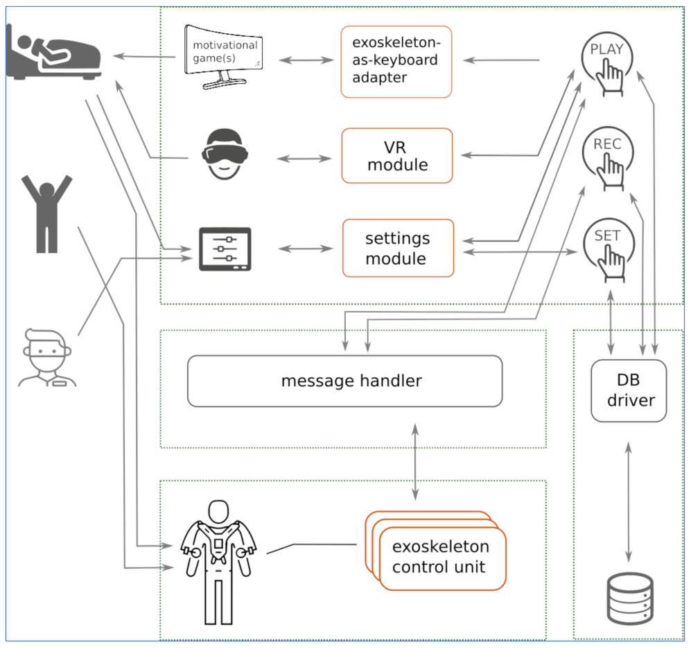
2.5.2. Operating Software Architecture
The architectural diagram of the CardioVR-ReTone operating platform is presented in
Figure 5, and was constructed using a distributed control approach (to be implemented over the ROS framework [
45]). The two user symbols depict the recovering patient (see Scenario 2 above) and the physiotherapist (see Scenario 1 above).
The exoskeleton sensors and actuators are controlled at a logical level by the “sensors” and “actuators” modules, which act as hardware drivers. These modules communicate with the “play” and “rec” modules via asynchronous messages. The (asynchronous) communication mechanism is coordinated by a message handler.
The “rec” module records the parameters of the sample rehabilitation exercises executed by the therapist assistant (see Scenario 1 above) and stores them in the DB as a “sample”. The “play” module moves the exoskeleton according to a sample of exercises and thus supports the patient in the required arm movements. The “set” module allows the physiotherapist to build the rehab journey of a patient (e.g., what exercises to perform in each rehab level) and store it in the database.
In the second interaction scenario, as the patient executes the rehabilitation exercises within a rehabilitation level, the communication node of the “play” module requests the movement parameters (X, Y, Z, and orientation angles of the TCP) from the exoskeleton control unit, via messages over a dedicated communication topic, with a 10 Hz frequency. Based on this data, the “play” module counts the movements done by the patient (by comparing them against the reference, i.e., the stored exercise template). It further sends the counter data to the VR game and to the “exoskeleton-as-keyboard” module. The VR game uses this data to visually correlate the avatar movements with the actual patient movements. If an external game is used as a motivator within a rehab level, the “exoskeleton-as-keyboard” module translates this data to virtual key presses that, in turn, control the external game (e.g., executing jumps, left or right turns).
The “settings module” is the business logic corresponding to the settings user interface, and the “VR module” is the business logic of the VR game. In the partially and resistive assisted scenario, an external motivational game (e.g., any endless runner or moto-race simple open-source game) can be played by the patient; to control the game, the patient movements are translated into virtual key presses by the “exoskeleton-as-keyboard” adapter. For instance, to control an endless runner game, one arm raise can be translated to a “jump” (key up).
2.5.3. Gaming Components
Two “game” components implement the motivational mechanisms discussed above: the VR game that accompanies the patient along their rehab journey (like the “main menu” of a game where you see/select the current level to play), and other (simple) games to accompany the patient along a single level. These are discussed below.
The VR game: to make the entire rehab journey easily understandable and fun, a VR game is being developed to act as an avatar “host” for the patient. It conveys information such as the current progress, what is coming next, and medical information related to the patient’s disease, cure, and recommended lifestyle. When presenting the next exercise level, the avatar explains the movements to be made and trains the patient to do them, while also providing feedback.
The hardware used to track the patient’s hand movements has been developed to make use of the Microsoft Kinect V2 motion sensing device.
Many researchers [
46] have started to develop various Exergame VR applications that make use of widely available and affordable motion sensors such as Microsoft Kinect, which have started to be used in various physical recovery activities [
47]. This sensor offers an accurate tracking system that can provide reliable posture analysis regarding the angular constraints of the patient’s hand movement. Thus, the patient will be encouraged by the VR exergame to define the required hand recovery movement.
The validity and reliability studies that make use of Microsoft Kinect V2 are widely available in the literature, where researchers have compared the real-time skeleton tracking system with advanced 3D motion tracking systems such as Vicon or as conventional clinical goniometers and digital goniometers. Other researchers [
30,
48] have compared the body movement recordings of both Vicon and Kinect datasets to identify movement patterns during exergaming. Other researchers have highlighted the current implications of virtual reality applications intended for cardiac rehabilitation exergaming [
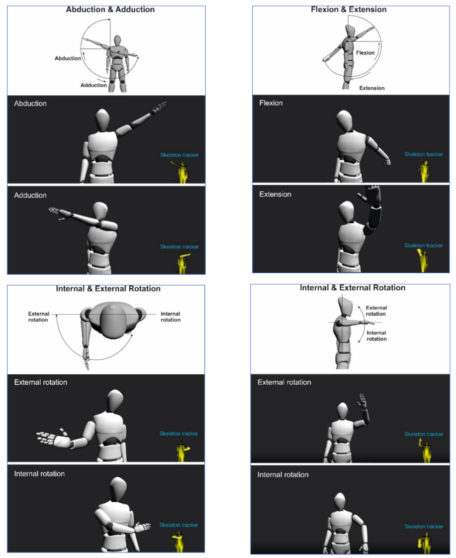
30]. These virtual reality applications have a promising impact to improve patient self-efficacy for exercise training using various digital hardware setups. The mostly common setups make use of affordable and widely available equipment such as a Kinect or various virtual reality head-mounted display (HMD) headsets. Various arm movements such as abduction, adduction, flexion, extension, internal, and external rotations have been analyzed. These are illustrated in
Figure 6.
The level games: to build enthusiasm, introduce fun into a rehab level, and to distract from potential pain, a simple game can be played while performing the exercises. To avoid boredom and to be able to adapt to each patient, any game (for which a valid license exists) can be used in this step.
The patient’s movements, either free or exoskeleton-assisted, are translated into keypresses: for instance, raising the arms can be equivalent to the “up” key or the difference in movement between the arms can correspond to the “left” or “right” key. Simple voice commands like “now” or “fire” can also be used as the “enter” or “space” key. At runtime, the “exoskeleton-as-keyboard” module sends the “translated” key presses to a computer running the external game. In the current software version, the Linux xdotool [
34] command line tool was used to simulate keyboard activity.
The movements described in
Figure 6 are in accordance with the CR protocol described in our previous work [
39] and in accordance with the available CR guidelines and international recommendations [
36].
4. Discussion
A new robotic exoskeleton with 12 DoFs for the upper limbs used in the rehabilitation of cardiac patients after open heart surgery was introduced in this paper. Our system uses six motors on each arm. Thus, in this article, the CardioVR-ReTone robotic exoskeleton, being symmetric, was considered a 6R serial structure robot for each arm.
Section 2.2 presented the geometrical and kinematic model of the right part of the exoskeleton—6R serial structure. The direct and inverse geometry equations for the mentioned structure were established using the matrix of locating algorithm, considering the minimum number of geometric or mechanical restrictions. The operational kinematic parameters expressing the movement of the end effector in Cartesian space were defined by the iterative algorithm. The kinematic control functions of the serial structure of type 6R were determined based on the inverse of the Jacobian matrix. As a major point to consider, the algorithmizing of the geometric and kinematic modelling of the CardioVR-ReTone robotic exoskeleton structures had some major advantages, as a simple geometric visualization of the characteristics of the different parameters considered the high degree of generalization, regardless of the complexity of the mechanical systems involved.
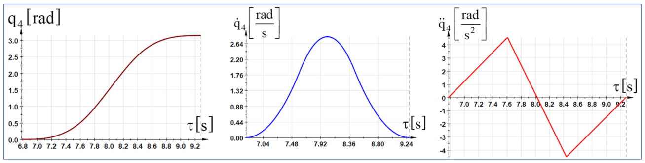
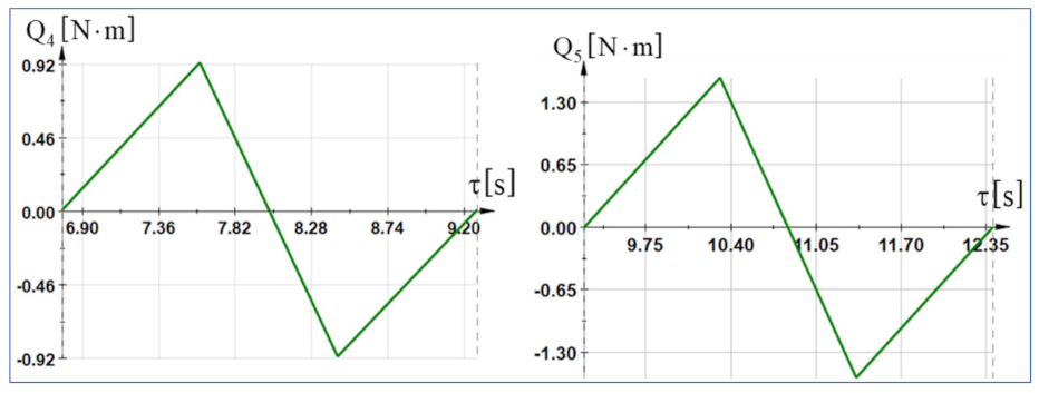
The dynamic control functions were determined using the fundamental notion as kinetic energy in the advanced mechanics of the mechanical systems. Starting from the differential principles of the analytical mechanics, specific to the holonomic mechanical systems, in which the serial structure of type 6R is inscribed and using the algorithm of the generalized forces in dynamics, the generalized driving forces were directly determined using analytical calculations. Further, the generalized variables that express the movement of the mechanical system can be replaced by polynomial functions of time according to the working process in which the serial robot structure is integrated. The polynomial functions of interpolation were determined as real variables for the description of the motion process. The expressions were substituted into the dynamic equations that led to the establishment of the variation laws of the driving moments.
Based on the kinematic and dynamic model, the control architecture was developed, and the electrical motors were chosen. Thus, the EC60 flat BLDC electric motor, coupled with harmonic drives, was chosen due to its good torque-to-weight ratio, compact size, low backlash, and ease of control. Considering the calculated torque, and taking into account the economic factors like discounts for more than three identical motors, the following actuators were selected for each exoskeleton arm: two AC-CPU17-100, one AC-CPU20-100, and three AC-CPU25-100. Every actuator has an incremental encoder.
The control architecture of the CardioVR-ReTone was developed to allow the deployment of several exoskeleton control modes: assistive, partially assistive, and resistive. An industrial open controller manufactured by Siemens, CPU 1515SP PC2, was considered the main control unit. The PLC had a CANOpen communication module, used to connect with every actuator EPOS4 controller and several IOs modules used to connect the signals from the exoskeleton joysticks and mechanical safety limit switches mounted on the exoskeleton’s structure. The mechanical safety limit switches were used to activate the safe torque off functionality of the actuators in cases of malfunction, considering the positioning process. The open controller operating system hosted the VR engine and Simulink. Simulink ran the kinematic algorithms and sent the positioning, speed, and torque data to every joint actuator controller. Feedback was received from every actuator controller and sent back to the Simulink Kinematics algorithm. Surface EMGs placed on human arms sent information about muscle activity using Bluetooth to the open controller, which fed the data to Simulink for processing and torque adjustment. The architecture of the CardioVR-ReTone operating platform was based on a distributed control approach; the ROS (Robot Operating System) platform is currently considered the first option for implementing control-related functions.
The early rehabilitation process of a patient after open-heart surgery is often long, painful, and lacks challenges and fun, especially in an unfavorable context like difficulties reaching a rehabilitation centre. Therefore, we envisaged extrinsic motivation mechanisms. These mechanisms were included in two game components—one to accompany the patient along their rehab journey, and one as a simple game that can be played while performing the exercises of a specific rehab level. The movements that the patient makes can be “translated” into virtual keypress events, and thus, via the “exoskeleton-as-keyboard” module, even external simple games can be used as motivational mechanisms. The entire rehabilitation process lifecycle, starting immediately after surgery, continuing at the patient’s home, and ending once the patient is completely recovered, drove the design of the interaction scenarios described in
Section 2.5. Similarly, the architecture of the CardioVR operating software was built to support the interaction scenarios of each user role (patient, therapist, and therapist assistant).
The article presents the CardioVR-ReTone exoskeleton, that has not been implemented in clinical practice yet, and might be, to our knowledge, the first model of its kind used for early CR after sternotomy. The CardioVR-ReTone exoskeleton successfully passed the software simulation tests. Before its implementation in clinical practice, the robotic system needs to pass laboratory tests with healthy volunteers. Further studies should be conducted to balance the efficacity, advantages, and disadvantages of the CardioVR-ReTone exoskeleton, as well as its sustainability and utility in clinical practice. Our entire medical testing protocol is described by our group in [
39]. The efficacity of the system will be also compared to usual CR, and will be assessed using several variables such as: quality of life; sternal stability; upper arm skeletal muscle function assessment; pain intensity; exercise protocol; cardiac response to exercise; and compliance/adherence dropout rates.
5. Conclusions
In this paper, the electromechanical design (geometric, kinematic, and dynamic model), control architecture, and VR software module of the CardioVR-ReTone robotic exoskeleton was presented. The CardioVR-ReTone robotic exoskeleton consists of two serial robotic arms, each with six DoFs, and with mirrored joints. The geometric, kinematic, and dynamic model presented in this article was developed for the right arm of the exoskeleton. From the geometric point of view, the two robotic arms are identical and the kinematic main difference between the right and left robotic arms is the rotation direction of certain joints.
The matrix of locating algorithm was used to determine the direct and inverse geometry equations for the stated construction, while taking into account the minimum number of geometric or mechanical constraints. The iterative algorithm defined the operational kinematic parameters representing the movement of the end effector in Cartesian space. The kinematic control functions of the serial structure of type 6R were determined based on the inverse of the Jacobian matrix. The dynamic control functions were calculated utilizing kinetic energy, a key concept in advanced mechanical systems mechanics. The generalized driving forces were directly computed using the algorithm of the generalized forces in dynamics and the differential principles of analytical mechanics, which are peculiar to holonomic mechanical systems in which the serial structure of type 6R is inscribed.
Developing a robotic exoskeleton for upper limbs that can support a cardiac patient following open-heart surgery during the early rehabilitation process necessitates a deep understanding of the kinematics and dynamics of the human upper limbs. The CardioVR-ReTone exoskeleton was devised following debates and discussions with cardiologists. The six-DoF robotic exoskeleton design relied significantly on the results obtained from these interactions to offer the necessary engineering specifications.
The design of the robotic exoskeleton included the proximal positioning of the harmonic drive’s motors, and open mechanical human–machine interfaces. High stiffness linkages and back-drivable transmissions without backlash are key features of the CardioVR-ReTone exoskeleton. The proposed exoskeleton structure does not use stiff elements for coupling the human arm with the exoskeleton articulation; instead, it relies on the rotation center to ensure optimal patient elbow joint articulation. This has a big impact on the comfort level of the human–robot interaction.
In terms of future development, the intention is to control the CardioVR-ReTone robotic exoskeleton with the help of a brain-controlled helmet. So far, we have managed to start an electric motor with the help of an Emotiv-Epoc+ 14-channel wireless EEG headset.


 ,
, 


