Article

Theoretical Derivation and Optimization Verification of BER for Indoor SWIPT Environments

1
Department of School of Electric and Information Engineering, Beibu Gulf University, Qinzhou 535011, China
2
Guangxi Academy of Transportation Sciences Co., Ltd., Nanning 530004, China
3
Department of Electrical and Computer and Engineering Department, Tamkang University, New Taipei City 25137, Taiwan
4
Department of Communications Engineering, Tohoku University, Sendai 980-8579, Japan
*
Author to whom correspondence should be addressed.
Symmetry 2020, 12(7), 1185; https://doi.org/10.3390/sym12071185
Submission received: 4 June 2020 / Revised: 1 July 2020 / Accepted: 11 July 2020 / Published: 17 July 2020
(This article belongs to the Special Issue Selected Papers from IIKII 2020 Conferences II)

Abstract

:
Symmetrical antenna array is useful for omni bearing beamforming adjustment with multiple receivers. Beam-forming techniques using evolution algorithms have been studied for multi-user resource allocation in simultaneous wireless information and power transfer (SWIPT) systems. In a high-capacity broadband communication system there are many users with wearable devices. A transmitter provides simultaneous wireless information and power to a particular receiver, and the other receivers harvest energy from the radio frequency while being idle. In addition, the ray bounce tracking method is used to estimate the multi-path channel, and the Fourier method is used to perform the time domain conversion. A simple method for reducing the frequency selective effort of the multiple channels using the feed line length instead of the digital phase shifts is proposed. The feed line length and excitation current of the transmitting antennas are adjusted to maximize the energy harvest efficiency under the bit error rate (BER) constraint. We use the time-domain multipath signal to calculate the BER, which includes the inter symbol interference for the wideband system. In addition, we use multi-objective function for optimization. To the best of our knowledge, resource allocation algorithms for this problem have not been reported in the literature. The optimal radiation patterns are synthesized by the asynchronous particle swarm optimization (APSO) and self-adaptive dynamic differential evolution (SADDE) algorithms. Both APSO and SADDE can form good patterns for the receiver for energy harvesting. However, APSO has a faster convergence speed than SADDE.

1. Introduction

Simultaneous wireless information and power transfer (SWIPT) has been widely investigated recently [1,2,3,4,5,6,7,8,9,10,11,12]. SWIPT does not only provide a high spectral efficiency of wireless systems, but it also provides energy via ambient radio frequency electromagnetic waves. SWIPT is able to support various sensor networks, the Internet of Things (IoT), and cellular systems [13]. In SWIPT systems, signals with information are used for communication and for energy extraction. Energy harvesting can allow for a longer lifetime of energy-constrained wireless devices.
A trade-off between the data rate and energy transfer for a narrow band signal was proposed in the literature [1]. Then, the authors of [2] used a frequency-selective channel with additive Gaussian noise. Another piece of research proposed a dynamic power splitting receiver to spilt the signal and decoded information, with a variable ratio of power to harvest energy [3]. A broadband system with multiplexing of the orthogonal frequency division and beamforming of the transmission was used for SWIPT. [4] However, the direct transmission of the wide band was not considered in the paper (without carrier). The authors of [5] studied a multiple-input multiple-output (MIMO) SWIPT system. The beamforming technique transmitted to the energy and the information receiver of the narrow band signal. Robust beamforming was studied on the assumption of imperfect channel state information at the transmitter in the literature [6]. In the work of [7], the analytic solution was used to optimize the beamforming technology of the SWIPT system. In the literature [10], the allocation of a multi-object resource for secured communication in recognizable radio networks was studied. However, the study only used an analytic solution to calculate the bit error rate (BER) with a statistical channel. In the work of [14], precoding optimization research reduced the resources required for computing, but energy was not taken into consideration.
Most papers deal with the optimal analytic solution with the signal-to-noise ratio constraint for narrow-band signals. However, there are no analytic solutions for BER in the wideband system. For wide-band signals, the weighting vector is assumed to be adjusted according to the different frequencies, and BER should consider the inter symbol interference. In this paper, for design simplicity, we controlled the feed line length and current of the antenna element by beamforming techniques, based on the frequency selective effect of the multipath channel instead of the digital phase shifters. The circular antenna array is useful for adjustment with multiple receivers, as the deployment is symmetrical. Moreover, the bit error rate performance was considered in the wireless wideband communication system. In this paper, a wideband circular array was used to synthesize the array pattern to maximize the energy harvesting efficiency with the BER constraint using evolution algorithms. In Section 2, we explain the model for our wide band system. In Section 3, we introduce the criterion for different objective function optimization. In Section 4, the mechanisms of the algorithms are introduced for optimization. Section 5 includes the discussion on the simulation results, and Section 6 concludes with the key point. The definition of parameters are conclude in Appendix A.

2. System Model

2.1. System Description

We considered an indoor SWIPT network for short-distance downlink communication, as shown in Figure 1. We had a base station with antennas of Nt > 1 and receivers of K equipped with one antenna. Both the transmitter and receivers used dipole antennas sharing the same spectrum. The transmitter provided SWIPT services to the receivers. In this system, the transmitter transfers information to one receiver, in which the information receiver divides 50% of the received signal for the harvested power, and the other receivers use all of the received signal as the harvested power. We formulated the object function for energy efficiency (EE) with the BER constraint for data communication. We adjusted the excited current and phase for each transmitter antenna, and maximized the wireless power transfer efficiency using the self-adaptive dynamic differential evolution (SADDE) algorithm and asynchronous particle swarm optimization (APSO).

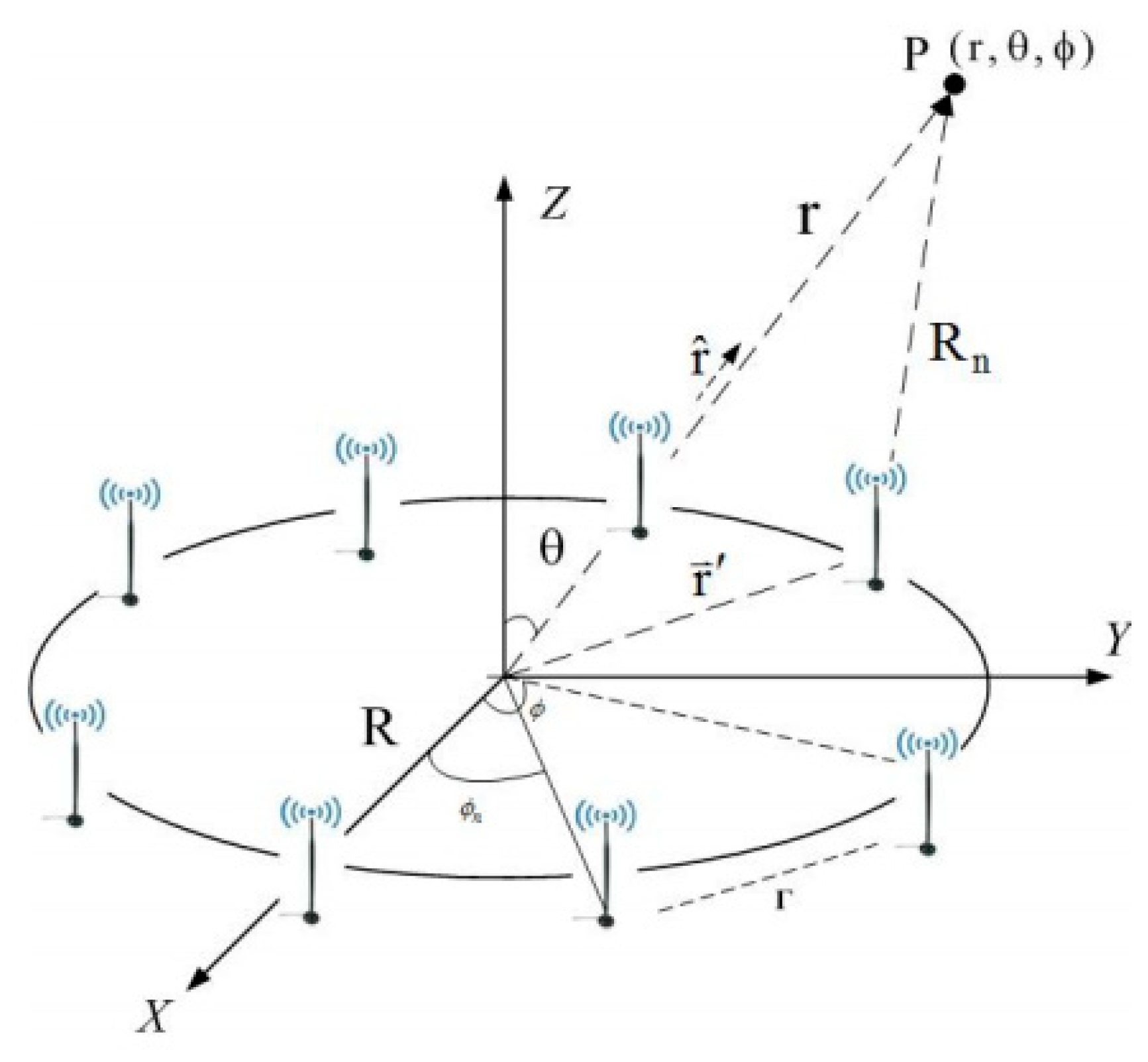
2.2. Transmitter Architecture Design

We exploited eight dipole antennas with ultra-wideband (UWB) to form an array in a circle for the transmitter, as seen in Figure 2.
A UWB printed dipole antenna is the individual element for the array. The radiation pattern is omnidirectional in the azimuth plane. The pattern of the array antenna is closely related to the arrangement of the antenna, as well as to the amplitude and the phase of the element of the antenna. With N antennas arranged uniformly in a circular array, the antenna pattern is assumed to be isotropic, and the total field can be expressed as
E t o t ( r , θ , ϕ ) = n = 1 N e j k R n R n ,   R n = ( r 2 + d 2 2 d r c o s ψ n )
where θ and ϕ represent the spherical coordinate system, a is the distance from original position to antenna position, and θ n and ϕ n are the spherical coordinates of the transmitting antenna ( θ n = θ + ψ n ). For the far field, the electrical field can be expressed as
E t o t ( r , θ , ϕ ) n = 1 N e j k ( r d ( r ^   · r   ¯ ) ) r = n = 1 N A n e j k r r ,   w h e r e   A n   i s   t h e   p h a s e   t e r m .
Note that
a ^ n · a ^ r = ( a ^ x c o s ϕ n s i n θ n + a ^ y s i n ϕ n s i n θ n + a ^ z c o s θ n ) · ( a ^ x c o s ϕ   s i n θ + a ^ y s i n ϕ   s i n θ + a ^ z c o s θ ) = c o s ϕ n s i n θ n c o s ϕ   s i n θ + s i n ϕ n s i n θ n s i n ϕ   s i n θ + c o s θ n c o s θ = s i n θ   s i n θ n c o s ( ϕ ϕ n ) + c o s θ n c o s θ .
The factor of this antenna array is written as
A F t ( θ , φ , f ) = n = 1 N t I n e j α n ( f ) e j k R s i n θ c o s ( φ φ n ) .
where I n is the excitation current voltage, k = 2π/λ is the wave-number (λ is the wavelength of the sinusoidal wave), and R is the radius of the circle. α n ( f ) is the phase delay in different frequencies, which corresponds to the feed line length, ln. α n ( f ) = 2 π f c ε r · l n , where C is the light speed and ε r is the permittivity of the feed line. We exploited eight antennas at the transmitter, positioned at φn = 0, 45, 90, 135, 180, 225, 270, and 315 degrees in the circle. Equation (4) derives the array factor of the transmitter as the following equation:
A F ( θ , φ , f ) = n = 1 N I n e j k R s i n θ c o s ( φ 2 π N ( n 1 ) ) .
The total radiation field of the array antenna is the product of the element radiation pattern and the array factor. The vector of the total radiation at the transmitting site is described as follows:
N ( θ , φ , f ) = AF t ( θ , φ , f ) . N e ( θ , φ , f ) .
Here, the three-dimensional radiation field vector N e ( θ , φ , f ) can be calculated by the structure simulation of the high-frequency.

2.3. Impulse Response

A ray-tracing technique can calculate the information on the channel state for different patterns of antenna radiation. It assumes that the transmitter sends out a pincushion of rays, and traces the environments until the rays either reach the receiver or lose enough power to the receiver. The weaker rays’ contribution to the received signal is ignorable. Rays are transmitted, reflected, or diffracted to the receiver. The receiver accepts signals in narrow bands near a certain frequency, and transforms them to the similar and complex signals. By using shooting and bouncing rays (SBR)/image techniques [15,16], the following equation induces the channel frequency response
H ( f ) = i = 1 N I M b i ( f ) e j θ i ( f )
where f is the frequency of the sinusoidal wave, i is the path index, θ i is the ith phase shift, b i is the ith receiving magnitude that depends on the radiation vector of the transmitter and receiver antenna, and N I M is the number of images. The frequency response of the ultra-wideband H U W B ( f ) form f1 to f2 can be expressed as
H U W B ( f   ) = n = f 1 n = f 2 H ω ( f ) δ ( f n Δ f ) .
In the calculation, the location of the image source is calculated by the method of ray tracing, while the channel frequency response is obtained using the height of the equivalent antenna. Then, applying an inverse fast Fourier transform converts the data in the frequency domain into time domain data in the wideband frequency system [17]. The channel frequency response is converted into a discrete time domain function, i.e., the ultra-wideband impulse response h U W B ( t ) with the Hermitian method and discrete fast inverse Fourier transform.

2.4. Receiver Architecture Design

We used power-splitting architecture in our system, as in Figure 3. The received radio frequency (RF) signals are divided for the information receiver and for the RF energy harvester with different power levels. When μ i is the fraction of RF signals for energy harvesting, μ i   [ 0 ,   1 ] is defined as the power-splitting coefficient for receiver i. This means that η is the portion of RF signals utilized for power gathering. Similarly, the following equation calculates the power of RF energy that is harvested at a receiver j (this receiver splits the power from the source):
P i , j = η P j | h i , j | 2 μ i .

3. Resource Allocation Problem Formulation

3.1. Quality of Service (QoS) Factor for Indoor SWIPT System

The target for the indoor SWIPT network is providing a wireless power transfer to receivers while transferring data to the desired receiver. Thus, we can define the quality of service (QoS) measurement factor in two ways—data quality and energy efficiency.
Here, we set H as the channel vectors between the desired receiver and the transmitter, G k as the channel vectors between the the kth idle receiver and transmitter, and w as the corresponding beam-forming vector. The elements of w are as follows:
W n = I n e j α n .
The multi-path channel with an impulse response is
h UWB ( t ) = i = 1 N α i δ ( t τ i )
where i is the index of the path, τ i is the time delay for the ith path, and α i is the attenuation of the path. The pulse stream is
x ( t ) = E st l = 0 p ( t l T d ) d
where Td is the time span of the signal. The pulse-amplitude modulation symbols d { ± 1 } are considered to be independently identically distributed, and the Gaussian waveform can be expressed as
p ( t ) = d 2 d t ( 1 2 π σ e t 2 2 σ 2 )
where σ is the standard deviation. The received signal is expressed as
r ( t ) = [ x ( t ) h U W B ( t ) ] + N ( t ) .
The receiver samples the signal with suitably delayed references as
q ( t ) = n = 0 p ( t τ 1 ( n 1 ) T d )
where τ 1 is the delayed time with the first revived wave. Here, the correlator output is
Z ( n ) = ( n 1 ) T d n T d { E st l = 0 p ( t l T d ) d h U W B ( t ) } q ( t ) d t + ( n 1 ) T d n T d N ( t ) q ( t ) d t   .
Z(n) is compared with a threshold between 1 and −1. The variance of the output noise is σ 2 = N 0 2 E s t . The probability of error on average for one bit is calculated as
P [ Z ( n ) | d ] = 1 2 e f r c [ V ( n ) 2 σ d N ] .
The data quality between the transmitter and the desired receiver for the bit error rate (BER) is as follows:
BER = n = 0 N P ( d N ) . 1 2 e r f c [ V ( t = n T d ) 2 σ . ( d N ) ]
where e r f c ( x ) = 2 2 x e y 2 d y is the complementary error function and { d n } = { d 0 , d 1 , d N } is the binary sequence. In the SWIPT system, energy is harvested by idle receivers harvested from the RF to extend their lifetime. The efficiency of energy harvesting is important in the system design of networks, and is defined as the ratio of total harvested power at the receivers and the total radiated power by the transmitter in the SWIPT system. The total harvested energy by the K idle receivers is calculated as
E k = f 1 f 2 w G k G k w Δ f
where denotes the conjugate transpose. The total energy harvested from all of the receivers is modeled as
H P ( w ) t o t a l = k = 1 K 1 η k E k + η λ f 1 f 2 ( w H H w ) Δ f
where we set η and η k as constants, 0 ≤ η ,   η k ≤ 1 for all k. This provides the conversion efficiency of the RF energy in converting the received radio signal to electrical energy by the desired receiver and K idle receiver. On the other hand, the energy radiated by the transmitter can be expressed as
T P ( w ) = f 1 f 2 w 2 Δ f .
Thus, the efficiency of energy harvesting in the SWIPT system is expressed as
η e f f ( w ) = H P ( w ) t o t a l T P ( w ) .

3.2. Optimization Problem Formulations

The problem formulation in our indoor SWIPT system aims to maximize the efficiency of energy harvesting and to provide reliable communication in the network. The problem formulation is defined as
maximize :   η e f f ( w ) , constraint :   BER W B E R
The system objective in Equation (23) is maximizing the efficiency of the energy harvesting of the system. W B E R is the constraint for the system parameter, which denotes the required BER to maintain the data quality [18].

4. Evolution Algorithms

To get the synthetic radiation pattern, the best combination of feed line lengths needs to be found. This can be done by changing the length of signal feeding line of the element in the circular array. Then, the efficiency of energy harvesting can be maximized for multi-users. We search for the best solution of the radiation pattern using the evolution method that converts the pattern problem into an optimization problem. The evolution method defines the fitness function with the constraint in Equation (23):
Objective   Function = 1 η e f f ( w )
If the particle does not satisfy the constraint condition, then the particle will be discarded. However, for increasing the convergence speed, we can add some penalty weighting value to the objective function. For instance, the penalty weighting value is set as 2. In other words, the objective value in Equation (24) will multiply by 2 if the constraint is violated. We can check the final objective value to know whether the constraint is satisfied or not. The numerical results show that the final particle satisfies the constraint.

4.1. APSO

The PSO method selects the best solution through the calculation of the generation to search for the solution [18,19,20,21]. This is called a synchronous update. As the equation of the particle swarming for the velocity update depends on the group experience, synchronously updating does not allow for the particle to refer the experience of a group in time, causing a slower convergence. Thus, we changed the synchronous update mode to an asynchronous one. The advantage of the method is that the group experience updates with an optimal solution can be found. The search process of the other particles will immediately learn the experience of the last group, thereby accelerating convergence and saving computation time. Detailed steps of the asynchronous particle swarm optimization can be found in the literature [18,19,20,21].

4.2. Self-Adaptive Dynamic Differential Evolution

The evolution method of the self-adaptive dynamic differential evolution (SADDE) algorithm is shown in the literature [21,22,23]. The dynamic difference evolution method treats each solution as a parameter vector and selects the difference in the vector of the parameters of each group. Then, the method multiplies it by a weighting factor of inertia and adds it to the optimal solution to generate a perturbation vector. This vector is used for the perturbation of the best solution to avoid in order to be regional extreme. The mating process has a plausible solution. If the new parametrical vector performs better than the optimal vector, then the new vector becomes the optimal vector, so the population in the dynamic differential algorithm is updated in a dynamic form. Please refer to the literature [22,23,24] for details.

5. Numerical Results

5.1. Environment Settings

The target for the indoor SWIPT network is to provide wireless power transfer to receivers while transferring data to the desired receiver. We set the frequency range from 4 GHz to 5 GHz with a spacing of Δ f = 20   MHz for the simulation in this study, using the regulations of the ultra-wideband indoor communication system developed by the Federal Communications Commission (FCC), R = 0.125 m, which corresponds to the adjacent distance between the antennas for the half wavelength of 4 GHz. The QoS measurement factor can be defined in two ways—data quality and energy efficiency. We simulated the proposed resource allocation schemes to evaluate the system performance. We investigated a realistic room environment, as shown in Figure 4. The concrete room length was 10 m, the width was 10 m, and the height was 3 m. We had two wooden bookcases and one working desk in the room, with heights of 2.5 m and 1 m, respectively. The Tx and Rx1, Rx2, Rx3, and Rx4 antennas were 0.5 m in height. The transmitter was a UWB dipole antenna circular array with 16 antennas. The transmitter Tx position was at 7 m, 6 m, and 0.5 m. The receiver antenna was one UWB dipole antenna. The receivers Rx1, Rx2, Rx3, and Rx4 positions were at 3 m, 9.5 m, and 0.5 m; 3 m, 7.5 m, and 0.5 m; 3 m, 5.5 m, and 0.5 m; and 3 m, 3.5 m, and 0.5 m, respectively. The frequency for the UWB was from 4 GHz to 5 GHz. The transmitted power for each transmitter antenna to the noise power ratio at the receiver side was 25 dB. Note that the signal to noise ratio (SNR) at the receiver is dependent on the distance and multipath. The angles from the transmitter to receivers were Rx1: 138.8°, Rx2: 159.4°, Rx3: 187.1°, and Rx4: 212.0°. Transmitter Tx transferred signals to all of the receivers. Receiver Rx1 split 50% of the signal as power, and used the other 50% signal to decode the data. Rx2 and Rx3 received all of the signals as harvested power. The maximum required BER for the signal at R1 was set as 10 5 .
With the impulse and the frequency responses of the channel, we calculated the received power and BER, respectively. As a result of the omnidirectional characteristic of the array element, the range of the frequency of the channel was from 4 to 5 GHz. The objective function was discussed for maximum harvested power and was searched by evolution algorithms. In our research, the objective function was the inverse of the energy efficiency in Equation (14), and the number of generations was set to 600. In other words, when the generation reached 600, the algorithm will be terminated. The relative parameters for SADDE and APSO are as following: population size is 30 and crossover probability is 0.8. Note that the minimum objective function corresponds to the maximum harvested power.

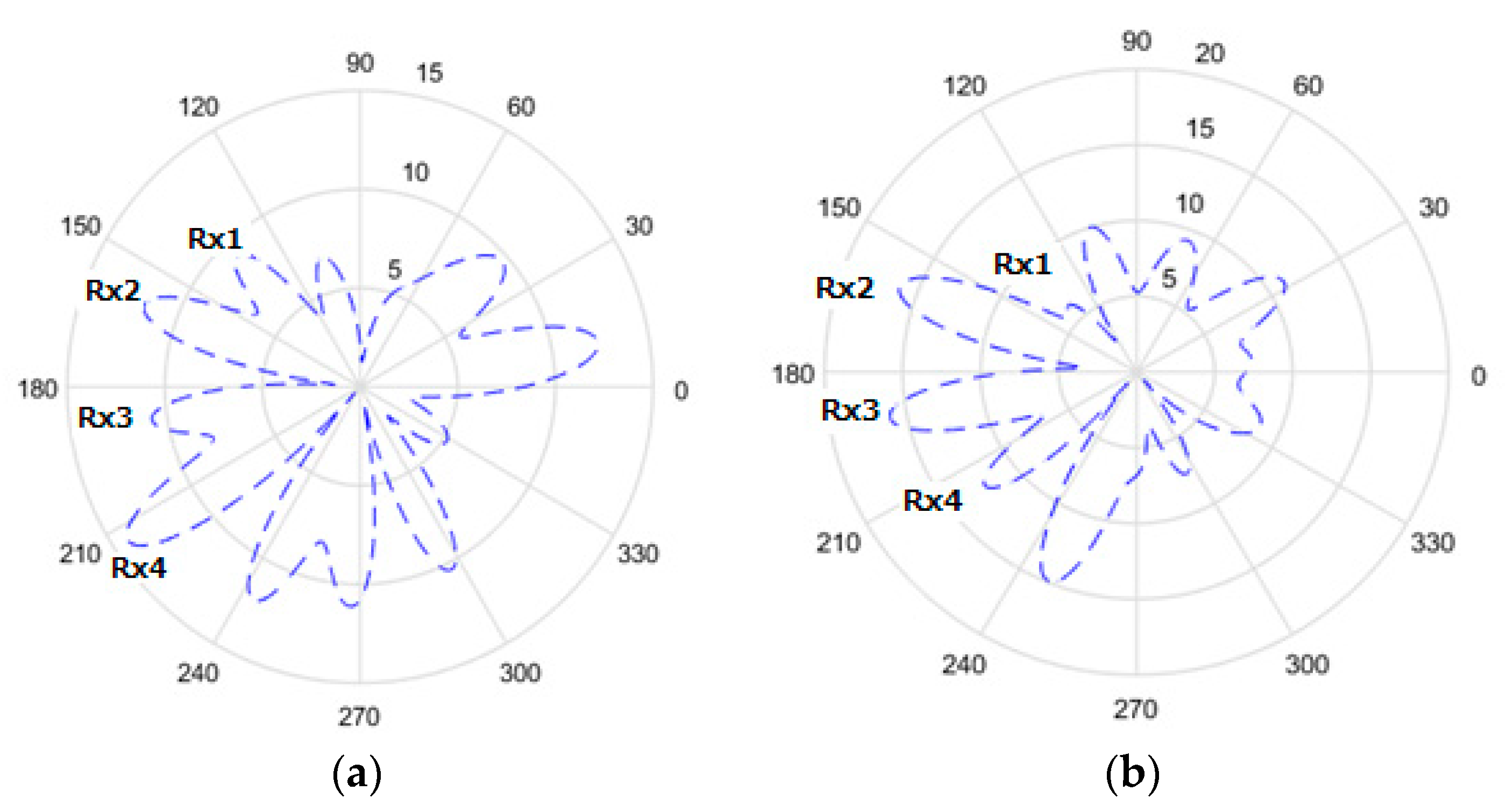
5.2. Simulation Result

Figure 5 shows the compared results of the objective values versus the generations for the SADDE and APSO algorithms in our simulation. The horizontal axis is the number of generations and the vertical axis is the fitness value that is equal to the inverse of the harvested power efficiency. It is found that the objective value almost converges near 400 generations with SADDE, and near 100 generations with APSO. According to this result, APSO has a faster convergence speed than SADDE. However, the final harvesting power ratio compared to the harvesting power ratio at 100 generation had only 1% improvement with APSO.
Figure 6a–d and Figure 7a–d show the radiation pattern for Tx to Rx in the x–y plane by SADDE and APSO at 100, 150, 250, and 600 generations. It is seen that the patterns of both algorithms point to all receivers at early generations, and they have similar radiation patterns as a result. In our case, we know that Rx1 uses half of the power received to decode information. To give the best power efficiency, Tx should send just enough power to Rx1 and try to maximize the power transfer to other receivers. Both SADDE and APSO adjusted the lowest amplitude gain for Rx1. For other receivers with SADDE, it was found that the amplitude gain point to Rx2, Rx3, and Rx4 reached near 15 to 13 at 250 generation. However, the distances of Rx2 and Rx3 were closer to the transmitter than Rx4. The amplitude gain point to Rx4 adjusted from near 15 to 12 at 600 generations. With APSO, the amplitude gain point to Rx2 and Rx3 reached 15 at 150 generations, and that to Rx4 adjusted from near 12 to 13 at 150 generations. The improvements of the total power harvesting ratio were about 2.45 by two algorithms.
Both SADDE and APSO adjust a strong side-lobe at 247°. Figure 8 shows this side-lobe will reflect to Rx4 by the concrete wall at the point of 4.4736, 0.0, and 0.5, with reflection angle of 23°, making a constructive interference for power transfer.

6. Conclusions

We studied a design of the algorithm for resource allocation in indoor networks with wireless power transfer on the basis of an objective optimization framework. We used wideband circular antenna arrays at the transmitter to maximize the power efficiency performance and keep the data quality. The BER should consider the inter symbol interference in a wideband system; instead, the BER only considered SNR in narrow band system. We employed SADDE and APSO algorithms to adjust the feed length and excitation voltages to synthesize the radiation pattern. Both the SADDE and APSO patterns pointed to all of the receivers at early generations, and had similar radiation patterns in the final result. The improvements in the total power harvesting ratio were about 2.45. Moreover, the results also reveal that the speed of convergence for APSO was faster than that for SADDE. The APSO uses only 100 generation for the final result.

Author Contributions

W.C., C.-C.C. and T.-T.H. contributed to the conception of the study. W.C., T.-T.H. and C.-C.C. contributed significantly to analysis and manusc ript preparation; W.C and Y.-T.C. performed the data analyses and wrote the manuscript; T.-T.H. and Y.-H.L. helped perform the analysis with constructive discussions. C.-C.C. and Q.C. major revised the manuscript in final version. All authors have read and agreed to the published version of the manuscript.

Funding

This research was funded by Research Initiation Project of Introducing High-level Talents from Beibu Gulf University of China, with grant number as 2017KYQD209.

Conflicts of Interest

The authors declare no conflict of interest.

Appendix A

List of mathematical symbols and abbreviations
Proper noun/mathematical symbolsAbbreviations/Description
Simultaneous wireless information and power transferSWIPT
Internet of ThingsIoT
Multiple-input multiple-outputMIMO
Energy efficiencyEE
Self-adaptive dynamic differential evolutionSADDE
Asynchronous particle swarm optimizationAPSO
Bit error rateBER
Ultra-widebandUWB
Quality of serviceQoS
Federal Communications CommissionFCC
E t o t ( r , θ , ϕ ) Electrical field
θ The spherical coordinate system
ϕ The spherical coordinate system
θ n The spherical coordinates of the transmitting antenna
ϕ n The spherical coordinates of the transmitting antenna
A n The phase term
A F   ( θ , φ , f ) The array factor
I n The excitation current voltage
λ The wavelength
k The wave-number
R the radius of circle array
ε r permittivity
l n the feed line length
N ( θ , φ , f ) the three-dimensional radiation field vector
H ( f ) the channel frequency response
b i the ith receiving magnitude
f the frequency of sinusoidal wave
θ i the ith phase shift
f 1 Start frequency
f 2 Stop frequency
H UWB ( f ) The frequency response of the ultra-wideband
P i , j The received RF signals power
μ i The fraction of RF signals
η The portion of RF signals
G k The channel vectors between the transmitter and the kth idle receiver
W n The corresponding beam-forming vector
h UWB ( t ) The multi-path channel with an impulse response
x ( t ) The pulse stream
τ i The time delay for the ith path
p ( t ) The Gaussian waveform
r ( t ) The received signal
q ( t ) The receiver samples the signal with suitably delayed references
Z ( n ) The output of the correlator
σ The variance of the output noise
α i The attenuation of the pat
T d The duration of the signal
d The pulse-amplitude modulation symbols
E k The total amount of energy harvested by the K idle receivers
H P ( w ) t o t a l The total energy harvested
T P ( w ) The energy radiated by the transmitter
η e f f ( w ) The energy harvesting efficiency
W B E R The constraint for the system parameter

References

  1. Varshney, L.R. Transporting Information and Energy Simultaneously. In Proceedings of the 2008 IEEE International Symposium on Information Theory, Toronto, ON, Canada, 6–11 July 2008; pp. 1612–1616. [Google Scholar] [CrossRef] [Green Version]
  2. Grover, P.; Sahai, A. Shannon meets Tesla: Wireless information and power transfer. In Proceedings of the 2010 IEEE International Symposium on Information Theory, Austin, TX, USA, 13–18 June 2010; pp. 2363–2367. [Google Scholar] [CrossRef]
  3. Zhou, X.; Zhang, R.; Ho, C. Wireless information and power transfer: Architecture design and rate–energy tradeoff. IEEE Trans. Commun. 2013, 61, 4754–4767. [Google Scholar] [CrossRef] [Green Version]
  4. Huang, K.; Larsson, E. Simultaneous Information and Power Transfer for Broadband Wireless Systems. IEEE Trans. Signal Process. 2013, 61, 5972–5986. [Google Scholar] [CrossRef] [Green Version]
  5. Zhang, R.; Ho, C.K. MIMO broadcasting for simultaneous wireless information and power transfer. IEEE Trans. Wirel. Commun. 2013, 12, 1989–2001. [Google Scholar] [CrossRef] [Green Version]
  6. Xiang, Z.; Tao, M. Robust Beamforming for Wireless Information and Power Transmission. IEEE Wirel. Commun. Lett. 2012, 1, 372–375. [Google Scholar] [CrossRef] [Green Version]
  7. Chen, H.; Xiao, L.; Li, Y.; Yang, D.; Zhou, X. Precoding Design and Power Allocation in Two-User MU-MIMO Wireless Ad Hoc Networks. Symmetry 2017, 9, 247. [Google Scholar] [CrossRef] [Green Version]
  8. Park, J.; Clerckx, B. Joint Wireless Information and Energy Transfer in a Two-User MIMO Interference Channel. IEEE Trans. Wirel. Commun. 2013, 12, 4210–4221. [Google Scholar] [CrossRef] [Green Version]
  9. Ng, D.W.K.; Lo, E.S.; Schober, R. Wireless Information and Power Transfer: Energy Efficiency Optimization in OFDMA Systems. IEEE Trans. Wirel. Commun. 2013, 12, 6352–6370. [Google Scholar] [CrossRef] [Green Version]
  10. Ng, D.W.K.; Lo, E.S.; Schober, R. Multi-Objective Resource Allocation for Secure Communication in Cognitive Radio Networks with Wireless Information and Power Transfer. IEEE Trans. Veh. Technol. 2015, 65, 1. [Google Scholar] [CrossRef] [Green Version]
  11. Tang, J.; So, D.K.C.; Zhao, N.; Shojaeifard, A.; Wong, K.-K. Energy Efficiency Optimization with SWIPT in MIMO Broadcast Channels for Internet of Things. IEEE Internet Things J. 2018, 5, 2605–2619. [Google Scholar] [CrossRef] [Green Version]
  12. Manisha, K.; Ravinder, B. Design of Microstrip Patch Antenna for Ultra Wide Band Applications. Int. J. Recent Adv. Sci. Eng. 2015, 2152–2156. [Google Scholar]
  13. Boulogeorgos, A.-A.; Diamantoulakis, P.D.; Karagiannidis, G.K. Low Power Wide Area Networks (LPWANs) for Internet of Things (IoT) Applications: Research Challenges and Future Trends. arXiv 2016, arXiv:1611.07449. [Google Scholar]
  14. Khan, I.; Henna, S.; Anjum, N.; Sali, A.; Khan, I.; Khan, Y.; Khattak, M.I.; Altaf, F. An Efficient Precoding Algorithm for mmWave Massive MIMO Systems. Symmetry 2019, 11, 1099. [Google Scholar] [CrossRef] [Green Version]
  15. Chen, S.H.; Jeng, S.K. An SBR/Image approach for indoor radio propagation in a corridor. IEICE Trans. Electron. 1995, 45, 98–106. [Google Scholar]
  16. Chen, S.H.; Jeng, S.K. SBR/Image approach for indoor radio propagation in tunnels with and without traffic. IEEE Trans. Veh. Techno. 1996, 45, 570–578. [Google Scholar] [CrossRef]
  17. Oppermann, I.; Hamalainen, M.; Iinatti, J. UWB Theory and Applications; John Wiley & Sons: Hoboken, NJ, USA, 2004. [Google Scholar]
  18. Chien, W.; Chiu, C.C.; Cheng, Y.-T.; Liao, S.-H.; Yen, H.-S. Multi-objective optimization for UWB antenna array by APSO algorithm. Telecommun. Syst. 2016, 64, 649–660. [Google Scholar] [CrossRef]
  19. Semnani, A.; Kamyab, M. An Enhanced Hybrid Method for Solving Inverse Scattering Problems. IEEE Trans. Magn. 2009, 45, 1534–1537. [Google Scholar] [CrossRef]
  20. Chiu, C.C.; Sun, C.-H.; Li, C.-L.; Huang, C.-H. Comparative Study of Some Population-Based Optimization Algorithms on Inverse Scattering of a Two-Dimensional Perfectly Conducting Cylinder in Dielectric Slab Medium. IEEE Trans. Geosci. Remote. Sens. 2012, 51, 2302–2315. [Google Scholar] [CrossRef]
  21. Hsieh, C.T.; Liao, S.H.; Chiu, C.C.; Ho, M.H. Optimal MIMO-WLAN Location for Transmitter in Indoor Environment Using Particle Swarm Optimizer. J. Appl. Sci. Eng. 2015, 18, 173–176. [Google Scholar]
  22. Lee, Y.-H.; Cheng, Y.-T.; Chiu, C.C.; Chang, S.-P. Microwave imaging for half-space imperfect conductors. Nondestruct. Test. Eval. 2015, 30, 49–62. [Google Scholar] [CrossRef]
  23. Yu, C.-Y.; Chiu, C.C.; Chou, Y.-K.; Shen, S.-C. Microwave Imaging in Frequency Domain for Through-Wall Multiple Conductors. J. Test. Eval. 2015, 44, 20140237. [Google Scholar] [CrossRef]
  24. Chiu, C.C.; Yen, C.-Y.; Lee, G.-Z. Dielectric objects reconstruction by combining subspace-based algorithm and randomly global optimization algorithm. J. Electromagn. Waves Appl. 2017, 32, 77–91. [Google Scholar] [CrossRef]
Figure 1. Network model of the system.
Symmetry 12 01185 g001
Figure 2. Circular ultra-wideband (UWB) dipole antennas.
Symmetry 12 01185 g002
Figure 3. Receiver architecture design for our system.
Symmetry 12 01185 g003
Figure 4. Environment model.
Symmetry 12 01185 g004
Figure 5. Objective value generations for the self-adaptive dynamic differential evolution (SADDE) and asynchronous particle swarm optimization (APSO) algorithms.
Symmetry 12 01185 g005
Figure 6. Radiation pattern for Tx to Rx by SADDE in different generations: (a) 100, (b) 150, (c) 250, and (d) 600.
Symmetry 12 01185 g006aSymmetry 12 01185 g006b
Figure 7. Radiation pattern for Tx to Rx by APSO in different generations: (a) 100, (b) 150, (c) 250, and (d) 600.
Symmetry 12 01185 g007
Figure 8. Reflection of the side-lobe at 247°.
Symmetry 12 01185 g008

