Article

Numerical Modeling of Sloshing Frequencies in Tanks with Structure Using New Presented DQM-BEM Technique

1
School of Economics and Management NJUST, Nanjing University of Science and Technology, Nanjing 210094, China
2
Department of Aerospace Engineering, Sharif University of Technology, P.O. Box 11155-8639, Tehran, Iran
3
Faculty of Mechanical Engineering, Shahrood University of Technology, Shahrood 3619995161, Iran
4
Institute of Research and Development, Duy Tan University, Da Nang 550000, Vietnam
5
Faculty of Medicine, Duy Tan University, Da Nang 550000, Vietnam
*
Author to whom correspondence should be addressed.
Symmetry 2020, 12(4), 655; https://doi.org/10.3390/sym12040655
Submission received: 20 March 2020 / Revised: 10 April 2020 / Accepted: 17 April 2020 / Published: 21 April 2020
(This article belongs to the Special Issue Turbulence and Multiphase Flows and Symmetry)

Abstract

:
The sloshing behavior of systems is influenced by different factors related to the liquid level and tank specifications. Different approaches are applicable for the assessment of sloshing behavior in a tank. In this paper, a new numerical model based on the differential quadrature method and boundary element approaches is adopted to investigate the sloshing behavior of a tank with an elastic thin-walled beam. The model is developed based on small slope considerations of the free surface. The main assumption of fluid modeling is homogeneity, isotropy, inviscid, and only limited compressibility of the liquid. Indeed, the formulation is represented based on the reduced-order method and then is employed for simulating the coupling between structure and fluid in symmetric test cases. The results are verified with the ANSYS and literature for symmetric rigid structural walls and then the code is employed to study the behavior of fluid-structure interaction in a symmetric tank with new and efficient immersed structure.

1. Introduction

The definition of sloshing in the hydrodynamic area [1,2,3] (motion of freeboard of liquid) comes from standing waves formed on the free surface of a liquid when a tank contended with liquid oscillates. Indeed, the dynamic behavior of the bilateral sloshing or motion of the freeboard of liquid can be changed based on the flexibility of tanks. The vibrational modeling behavior of the container has been investigated in civil applications [4,5] such as pools, and nuclear or fuel tanks located in the fuselage of airplanes, which are some examples used for this definition of the liquid freeboard in engineering problems [6,7]. NASA has studied sloshing with Abramson and Silverman [8] and made a liquid sloshing dynamics book with Ibrahim [9], which are the significant sources in this subject.
The investigations are commonly conducted on the coupled behavior of the fluid-structure domain, and this phenomenon is controlled using the arrangement of bottom-mounted baffles [10] or submerged components. The effects of the baffle on the dynamic response of the sloshing-structure coupled system are investigated for a variety of tank shapes [11,12,13]. In addition, a submerged structure is a useful component of sloshing disturbance studied by the new represented method. Watson and Evans [14], by using Galerkin expansion approaches, investigated the effects of the block shape of rigid submerged structures on the behavior of sloshing in rectangular liquid tanks. Choun and Yun [15,16], based on linearized theory, extracted the response of rectangular containers with a submerged structure under a typical earthquake. Mitra and Sinhamahapatra [17], using the finite element method (FEM), investigated the effect of bottom-mounted rectangular submerged structures on the sloshing frequencies with rigid considerations wall. Among the most well-known numerical solution approaches, the differential quadrature method (DQM) was introduced in 1971 and showed its capability in the application of many engineering problems [18]. Indeed, the need for a guess function, which is the base of the assumed mode technique, is not required in the DQM, and the approaches are followed with low computational cost; thus, many researchers tend to apply this method for their applied problems. Bert et al. [19,20,21] developed the structural equation of a linear problem and represented the small differences between their results and those of the literature. Hassan et al. [22] studied the vibrational behavior of a tapered beam on the foundation using the DQM with static and dynamic supposition. Kang et al. [23] investigated the extensional vibration analysis of curved beams using the DQM. They concluded that the differential quadrature method with only a limited number of grid meshes represents highly accurate results.
Among the numerical engineering solution techniques that are commonly based on the finite element, finite difference, finite volume method, etc. [24,25,26,27,28], the boundary element method (BEM) [29] is very efficient and convenient for fluid mechanics, especially sloshing problems. Many studies have been conducted [30,31,32,33] to show the capability of the BEM for modeling and represent a sloshing solution in 2D and 3D tanks.
A flexible structure, located horizontally and vertically on the top or bottom of the liquid containers, in addition to the above-mentioned baffle structures [34], is another useful component that can reduce the sloshing disturbances. Therefore, in this study the novelty of rigid and flexible structures using the DQM-BEM model is presented. Firstly, this model is applied for a symmetric rigid tank with flexible thin features to compare with ANSYS and then the results for the description of fluid-structure interaction are highlighted.

2. Governing Equations

In the following section, the equations of the coupled problem are derived for both domains. Indeed, the equations of the walls of the container are represented based on the DQM method, and the fluid domain is discretized by BEM approaches. In addition, the simplified form of the structure–liquid systems based on the reduced-order approach is represented. Afterward, by using the DQM-BEM method, a solution is represented.

2.1. Flow-Field Governing Equations

For the sloshing problem, in addition to considering the internal dynamics of the fluid, governing equations in the freeboard and the interface of the fluid and structure must be applied. Assuming a homogeneous, isotropic, and inviscid flow for the internal field, the governing equation for the velocity potential ( ϕ ) is
2 ϕ = 0
The boundary conditions on the free surface with linearized dynamic suppositions result in
ϕ n | f r e e _ s u r f a c e = 1 g ϕ ¨
where g is gravitational acceleration and the value of n is the derivative operator in outward normal directions for the tank wall and the immersed structure. With the impermeability constraints of the walls of the tank and the submerged or immersed structure, the boundary condition on the fluid-structure interface can be expressed as
ϕ n | W a l l = W ˙ s
where W s denotes the displacement field of the flexible structure.

2.2. Developing the Boundary Element Model

The boundary element method is broadly employed for various engineering problems, especially for fluid mechanics. Meshing the boundary instead of the whole domain can be taken as the main advantage of the BEM. As the fluid is considered isotropic, inviscid, and compressible, the Laplace equation can be employed for developing the liquid domain formulation. The fundamental solution of Laplace’s represented model can be extracted by a unit source of the potential field region ( ϕ ), which can be expressed as
ϕ = 1 2 π ln ( 1 r )
where r is defined as the distance from the source point. Using Green’s second identity, the following equation is obtained:
C i ϕ i = ( ϕ * q q ϕ * ) d s
where q = ϕ n , q * = ϕ * n and C i is a coefficient that is evaluated based on the spatial angles related to the source point.
By discretizing the integrals in Equation (5) on the boundaries and using the collocation point method, the influence matrices can be represented as follows:
A Φ B Q = 0
in which two parameters Φ and Q are introduced as the potential and flux density vectors at all nodes in the domain, respectively.

2.3. Fluid–Solid Interaction Modeling

In investigating the sloshing behavior of a system, representing a model based on the fluid–structure interaction formulation plays a key role. In this regard, it is crucial to consider it and employ appropriate models. The structural model of walls can be obtained from the following equation:
M W ¨ s + K W s = F
Here, M and K are mass and stiffness matrices, and F is defined as the external loads vector, respectively. Using modal expansion and introducing W = W ¯ i η i one can show the mentioned equation is as follow:
η ¨ i + ω i 2 η i ( t ) = F i ¯
where ω i are the natural frequencies of the structure and F i ¯ arise by 0 l w ¯ i . p d s , where p is the dynamic pressure on the structure due to sloshing. Based on the unsteady Bernoulli supposition, p on the wall of the tank and immersed structure is equal to ρ f ϕ ˙ wall where ρ f is the density of the fluid. So F ¯ can be expressed as the following matrix:
F ¯ = H ¯ ϕ ˙ w
where H ¯ is produced from approximations p on the wall with linear elements.
Indeed, the structural mode shape ( W ¯ i ) is obtained using DQM method based on the following formulation:
m [ I ] w ¨ d + k [ I ] w d = 0
where w is the transverse displacement, k is the stiffness, m is the mass of the system, and I respectively. Using DQM technique Equation (7) is presented as:
m [ I ] w ¨ d + k [ K B d ] w d = 0
Therefore, the stiffness matrix can be divided into the boundary ( K B d b ) and internal domain ( K B d d ):
m [ I ] w ¨ d + k ( [ K B d d ] + [ K B d b ] ) w d = 0
By enforcing the boundary condition on ( 1 , 2 , , N 1 , N ) points, the stiffness matrix on the boundary is presented as
[ K B b ] w = 0
Using the stiffness matrix related to the boundary points, the relation between the boundary and domain displacement is obtained as
[ K B b b K B b d ] { w b w d } = 0 w b = ( [ K B b b ] 1 [ K B b d ] ) w d
Therefore, the DQM form of the structural equation is presented as
m [ I ] w ¨ d + [ K B ] w d = 0
where K B is
[ K B ] = E I ( [ K B d d ] [ K B d b ] [ K B b b ] 1 [ K B b d ] )
Thus, using the modal technique for the boundary element matrix, which is blocked in two sections (free surface section and wall section), Equation (6) can be written as
A 11 ϕ f s + A 12 ϕ w = B 11 q f s B 12 W ¯ i η ˙ i
A 21 ϕ f s + A 22 ϕ w = B 21 q f s B 22 W ¯ i η ˙ i
Thus, ϕ w equals
ϕ w = A 22 1 ( A 21 ϕ f s + B 21 q f s B 22 W ¯ i η ˙ i )
Substituting Equation (16) into Equation (17) results in
q f s = D ϕ f s E W ¯ i η ˙ i
where D and E are introduced with the following relationships:
D = ( A 11 A 12 A 22 1 A 21 ) ( B 11 A 12 A 22 1 B 21 ) 1
E = ( B 11 A 12 A 22 1 B 21 ) 1 ( A 12 A 22 1 B 22 B 12 )
Thus, the free-surface governing equation equals
ϕ ¨ f s + g D ϕ f s = g . E W ¯ i η ˙ i
Finally, the combination of two Equations (8) and (22) constitutes our Fluid Structure Interaction model.

3. Numerical Results

The sloshing modes of systems can be investigated by different tools and methods. Some of the most applicable ones that are compared here are represented in Figure 1.
Numerical methods are employable in different fields of engineering problems [35,36]. In this section, the precision of the extracted result is assessed by comparing the results to the numerical data obtained by ANSYS and the literature. As shown in Figure 2, different factors affect the sloshing frequency. In this research, various case studies with different geometries are considered to evaluate the validity of the proposed model. Afterward, the effects of new application tools, located on the top of the tank and called the immersed structure with two rigid and flexible walls, on the sloshing frequencies are studied.

3.1. Test Case 1

As illustrated in Figure 3, the verification example [17,37] comprise rigid rectangular block-shaped walls located at the middle of the rigid container. Indeed, the submerged structure has a height ( h ) and a 30 m width ( W ) with 13 m liquid depth ( d ) of 13 m. Here, the computation is performed several times with several block heights (h). Table 1 lists the comparison between ANSYS, the present model, and what is extracted from the literature [17,37] in different h/d ratios. The study indicates a good agreement between the present model, ANSYS, and the literature for all the test cases. Indeed, comparing the results obtained by the currently used approach to the previous data in the literature reveals that the maximum relative error has a difference of approximately 0.3%. In addition, it can be observed that the obtained data by this approach is closer to the data obtained by ANSYS in the rigid mode, which indicate the reliability of the model and its potential for utilization instead of numerical approaches, which are time-consuming.

3.2. Test Case 2

In the second test case, we use the previous tank with an elastic thin-walled submerged structure [32] and rigid walls (Table 2) in the fluid (blue domain) to validate the result of the DQM-BEM model (Figure 4).
The thickness of the submerged walls in the represented FSI model is 5 cm with a h/d ratio of 0.8. Here, the mode shapes of the submerged structures are extracted using DQM, and its related natural frequencies compared to the literature are reported in Table 3. The material properties of the fluid and structure are represented as
E = 200   Gpa , v = 0.3 ,   t = 5   cm ,   ρ s = 7800   kg / m 3 ,   ρ f = 1000   kg / m 3
where E ,   v ,   t ,   ρ s ,   ρ f are Young’s modulus, Poisson’s ratio, the thickness, structural density, and fluid density, respectively.
The results of the structural calculation are extracted with a 40-grid mesh and indicates an acceptable agreement with the literature.
In addition, the presented ROM (Reduced Order Modeling) form of the DQM-BEM model using three structural mode shapes has been applied to calculate the natural frequencies of the coupled system versus the flexibility parameter (Figure 5). The flexibility parameter of the submerged structure ( F S ) as the non-dimensional formulation can be expressed as follows:
F S = ρ f ( 1 ϑ 2 ) W 2 E ω 0 2 ( W t ) 3
where W is the width of the submerged structure and ω 0 is the first sloshing frequency. Comparison between the results proves the capability of the represented model for estimating the dynamic behavior of sloshing in the liquid tank with a flexible submerged structure.

3.3. Test Case 3

The third test case is an efficient immersed application tool, which is introduced here to remark its effect on sloshing frequencies. First, the tank configuration with a rigid immersed structure in the rigid tank containing fluid (blue domain) is used as shown in Figure 6, and the elasticity effect of the walls on the sloshing frequencies is then investigated. The results of the presented model are compared to ANSYS in rigid modes (Figure 7) and are listed in the Table 4.
The size of the immersed beam and tank components are presented below
D = 1   m ,   L = 6.09   m ,   H = 3.04   m ,   T = 6   cm
where D and T are defined as depth and length of the immersed beam in the fluid, L and H are introduced as length and height of the tank, respectively.
As represented in Table 4, the calculations show a maximum difference of about 1.57% for the second mode compared to ANSYS and demonstrates the applicability and accuracy of the proposed method for this case study.

3.4. Test Case 4

The fourth test case is the same as the previously mentioned tank (Figure 8); however, an immersed elastic thin-walled beam requires consideration. The thickness of the beam wall in the represented FSI model is 1 mm. The following structural boundary condition and the material properties of the immersed structure (structural steel) are represented in Table 5. The mode shapes of the immersed structures are extracted using the DQM, and its related natural frequencies are reported in Table 6.
In addition, the presented model using three structural mode shapes has been applied to calculate the natural frequencies of the coupled system (Table 7). The flexibility parameter ( F I ) of the immersed structure, which is dimensionless, can be defined as
F I = ρ f ( 1 ϑ 2 ) T 2 E ω 0 2 ( T t ) 3
In the above equation, T and ω 0 are also the width and the first sloshing frequency of the immersed structure, respectively. The material properties of the flexible immersed component are represented as:
Material: E = 200   Gpa ,   v = 0.3 ,   t = 5   cm ,   ρ s = 7800   kg / m 3 ,   ρ f = 1000   kg / m 3 .
On the basis of the data in Table 6 and Table 7, existence of the fluid in the system leads to a decrease in structural frequency. This reduction in frequency is mainly due to dividing the freeboard of the fluid into a small zone. In addition, according to the represented results in Table 3 and Table 5, in the presence of an elastic structure, a reduction in sloshing frequency is observed. This decrease in frequency can be attributed to the immersed structure flexibility and its interaction with the fluid.
Figure 9 illustrates the variation in the first three sloshing frequencies versus the flexibility parameter of the immersed structure. The figure highlights the direct relation of sloshing frequencies to the flexibility parameter for tanks with immersed structures. Indeed, the coupling of the structures and fluid can be inferred in the high flexibility parameters. In fact, this means that the coupling has occurred earlier when the dynamic behavior of the two systems is close to each other.

4. Conclusions

Different methods are applicable for the sloshing behavior investigation of various structures. The accuracy and appropriateness of the previously utilized approaches are dependent on the physics of the problems and grid meshing as the applied numerical methods are time-consuming; the analytical approaches are superior in terms of time and computational cost. In this study, a semi-analytical approach is represented based on a coupled DQM-BEM model for the investigation of sloshing in symmetric tanks with a flexible immersed and submerged structure. The represented tank and all features are considered as symmetric rectangular and trapezoid shapes. In the first step, the results of the presented model are compared to those of the literature and ANSYS for a tank with a submerged structure. Then, the results for a tank with a rigid immersed structure compared to ANSYS indicates that a very good agreement has been achieved, and the natural frequencies of the fluid–solid interaction model for a tank with a flexible immersed thin-walled beam is finally investigated. From the emerged results of the represented test cases, the following additional points can be concluded:
1-
According to the model outputs, the existence of fluid in the investigated system leads to the reduction in the frequencies.
2-
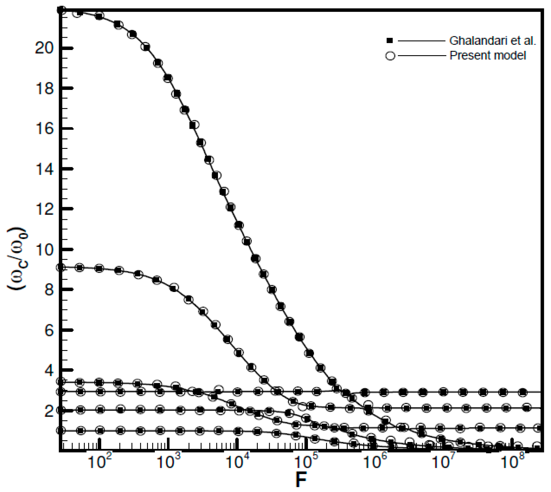
Comparing the results of the model to the data of previous studies shows a maximum relative error of 1.5% between the DQM-BEM model and literature, indicating the reliability of the results obtained by the developed model.
3-
The effect of the immersed structures on the dynamic response of the sloshing is more tangible than the submerged structure.
4-
The sloshing effect on the structural frequencies is revealed itself in a high-flexibility parameter for both submerged and immersed structures.

Author Contributions

Z.W. and J.F. have conducted modeling and investigation of results. M.G. has revised and written the manuscript. The study has been supervised by A.M. and Z.A. All authors have read and agreed to the published version of the manuscript.

Funding

This research received no external funding.

Conflicts of Interest

The authors declare no conflict of interest.

References

  1. Shadloo, M.S.; Weiss, R.; Yildiz, M.; Dalrymple, R.A. Numerical simulation of long wave runup for breaking and nonbreaking waves. Int. J. Offshore Polar Eng. 2015, 25, 1–7. [Google Scholar]
  2. Hopp-Hirschler, M.; Shadloo, M.S.; Nieken, U. A smoothed particle hydrodynamics approach for thermo-capillary flows. Comput. Fluids 2018, 176, 1–19. [Google Scholar] [CrossRef]
  3. Almasi, F.; Shadloo, M.S.; Hadjadj, A.; Ozbulut, M.; Tofighi, N.; Yildiz, M. Numerical simulations of multi-phase electro-hydrodynamics flows using a simple incompressible smoothed particle hydrodynamics method. Comput. Math. Appl. 2019. [Google Scholar] [CrossRef]
  4. Jiang, Y.; Dahi-Taleghani, A. Modified extended finite element methods for gas flow in fractured reservoirs: A pseudo-pressure approach. J. Energy Resour. Technol. 2018, 140, 073101. [Google Scholar] [CrossRef]
  5. Tarfaoui, M.; Shah, O.R.; Nachtane, M. Design and optimization of composite offshore wind turbine blades. J. Energy Resour. Technol. 2019, 141, 051204. [Google Scholar] [CrossRef]
  6. Wang, N.; Maleki, A.; Alhuyi Nazari, M.; Tlili, I.; Safdari Shadloo, M. Thermal conductivity modeling of nanofluids contain MgO particles by employing different approaches. Symmetry 2020, 12, 206. [Google Scholar] [CrossRef] [Green Version]
  7. Abdelmalek, Z.; Alamian, R.; Shadloo, M.S.; Maleki, A.; Karimipour, A. Numerical study on the performance of a homogeneous charge compression ignition engine fueled with different blends of biodiesel. J. Therm. Anal. Calorim. 2020, 1–11. [Google Scholar] [CrossRef]
  8. Abramson, H.N. The dynamic behavior of liquids in moving containers. NASA SP-106. NASA Spec. Publ. 1966, 106, 1–21. [Google Scholar]
  9. Ibrahim, R.A. Liquid Sloshing Dynamics: Theory and Applications; Cambridge University Press: Cambridge, UK, 2005; ISBN 1139444131. [Google Scholar]
  10. Jamalabadi, M.Y.A.; Ho-Huu, V.; Nguyen, T.K. Optimal design of circular baffles on sloshing in a rectangular tank horizontally coupled by structure. Water 2018, 10, 1504. [Google Scholar] [CrossRef] [Green Version]
  11. Gedikli, A.; Ergüven, M.E. Evaluation of sloshing problem by variational boundary element method. Eng. Anal. Bound. Elem. 2003, 27, 935–943. [Google Scholar] [CrossRef]
  12. Biswal, K.C.; Bhattacharyya, S.K. Dynamic response of structure coupled with liquid sloshing in a laminated composite cylindrical tank with baffle. Finite Elem. Anal. Des. 2010, 46, 966–981. [Google Scholar] [CrossRef]
  13. Scholl, H.F.; Stephens, D.G. Effectiveness of Flexible and Rigid Ring Baffles for Damping Liquid Oscillations in Large-Scale Cylindrical Tanks; National Aeronautics and Space Administration: Washington, DC, USA, 1967.
  14. Watson, E.B.B.; Evans, D.V. Resonant frequencies of a fluid in containers with internal bodies. J. Eng. Math. 1991, 25, 115–135. [Google Scholar] [CrossRef]
  15. Choun, Y.-S.; Yun, C.-B. Sloshing characteristics in rectangular tanks with a submerged block. Comput. Struct. 1996, 61, 401–413. [Google Scholar] [CrossRef]
  16. Choun, Y.; Yun, C. Sloshing analysis of rectangular tanks with a submerged structure by using small-amplitude water wave theory. Earthq. Eng. Struct. Dyn. 1999, 28, 763–783. [Google Scholar] [CrossRef]
  17. Mitra, S.; Sinhamahapatra, K.P. Slosh dynamics of liquid-filled containers with submerged components using pressure-based finite element method. J. Sound Vib. 2007, 304, 361–381. [Google Scholar] [CrossRef]
  18. Bellman, R.; Casti, J. Differential quadrature and long-term integration. J. Math. Anal. Appl. 1971, 34, 235–238. [Google Scholar] [CrossRef] [Green Version]
  19. Li, Z.; Hu, T.; Tao, Y.; Zhang, T.; Li, Z. Fast calculation method for transient response of transmission line based on chebyshev pseudospectral–two-step three-order boundary value coupled method. Symmetry 2019, 11, 721. [Google Scholar] [CrossRef] [Green Version]
  20. Malik, M.; Bert, C.W. Three-dimensional elasticity solutions for free vibrations of rectangular plates by the differential quadrature method. Int. J. Solids Struct. 1998, 35, 299–318. [Google Scholar] [CrossRef]
  21. Striz, A.G.; Jang, S.K.; Bert, C.W. Nonlinear bending analysis of thin circular plates by differential quadrature. Thin-Walled Struct. 1988, 6, 51–62. [Google Scholar] [CrossRef]
  22. Jang, S.K.; Bert, C.W.; Striz, A.G. Application of differential quadrature to static analysis of structural components. Int. J. Numer. Methods Eng. 1989, 28, 561–577. [Google Scholar] [CrossRef]
  23. Kang, K.-J.; Kim, B.-S. In-Plane Extensional Vibration Analysis of Curved Beams Using DQM. J. Korean Soc. Saf. 2002, 17, 99–104. [Google Scholar]
  24. Hassan, M.T.; Nassar, M. Analysis of stressed Timoshenko beams on two parameter foundations. Ksce J. Civ. Eng. 2015, 19, 173–179. [Google Scholar] [CrossRef]
  25. Ghalandari, M.; Shamshirband, S.; Mosavi, A.; Chau, K. Flutter speed estimation using presented differential quadrature method formulation. Eng. Appl. Comput. Fluid Mech. 2019, 13, 804–810. [Google Scholar] [CrossRef] [Green Version]
  26. Ghalandari, M.; Mirzadeh Koohshahi, E.; Mohamadian, F.; Shamshirband, S.; Chau, K.W. Numerical simulation of nanofluid flow inside a root canal. Eng. Appl. Comput. Fluid Mech. 2019, 13, 254–264. [Google Scholar] [CrossRef]
  27. Ghalandari, M.; Ziamolki, A.; Mosavi, A. Mechanics Aeromechanical optimization of first row compressor test stand blades using a hybrid machine learning model of genetic algorithm, artificial neural networks and design of experiments. Eng. Appl. Comput. Fluid Mech. 2019, 13, 892–904. [Google Scholar]
  28. Alizadeh, H.; Ghasempour, R.; Shafii, M.B.; Ahmadi, M.H.; Yan, W.-M.; Nazari, M.A. Numerical simulation of PV cooling by using single turn pulsating heat pipe. Int. J. Heat Mass Transf. 2018, 127, 203–208. [Google Scholar] [CrossRef]
  29. Zarandi, S.; Lai, H.-W.; Wang, Y.-C.; Aizikovich, S. Residual stress analysis of an orthotropic composite cylinder under thermal loading and unloading. Symmetry 2019, 11, 320. [Google Scholar] [CrossRef] [Green Version]
  30. Zhang, M.; Ayala, L.F. A general boundary integral solution for fluid flow analysis in reservoirs with complex fracture geometries. J. Energy Resour. Technol. 2018, 140, 052907. [Google Scholar] [CrossRef]
  31. Christensen, E.; Brunty, J.; Christensen, E.; Brunty, J. Launch vehicle slosh and hydroelastic loads analysis using the boundary element method. In Proceedings of the 38th Structures, Structural Dynamics, and Materials Conference, Kissimmee, FL, USA, 7–10 April 1997; p. 1036. [Google Scholar]
  32. Dutta, S.; Laha, M.K. Analysis of the small amplitude sloshing of a liquid in a rigid container of arbitrary shape using a low-order boundary element method. Int. J. Numer. Methods Eng. 2000, 47, 1633–1648. [Google Scholar] [CrossRef]
  33. Nakayama, T.; Washizu, K. The boundary element method applied to the analysis of two-dimensional nonlinear sloshing problems. Int. J. Numer. Methods Eng. 1981, 17, 1631–1646. [Google Scholar] [CrossRef]
  34. Zhu, R.; Saito, K. Multiple domain boundary element method applied to fluid motions in a tank with internal structure. J. Soc. Nav. Archit. Jpn. 2000, 2000, 135–141. [Google Scholar] [CrossRef]
  35. Ghalandari, M.; Bornassi, S.; Ahmadi, M.H. Investigation frequencies of elastic submerged structure on sloshing. Eng. Appl. Comput. Fluid Mech. 2019, 13, 519–528. [Google Scholar]
  36. Jamalabadi, M.Y.A.; Alamian, R.; Yan, W.M.; Li, L.K.B.; Leveneur, S.; Shadloo, M.S. Effects of nanoparticle enhanced lubricant films in thermal design of plain journal bearings at high reynolds numbers. Symmetry 2019, 11, 1–18. [Google Scholar]
  37. Ghalandari, M.; Bornassi, S.; Shamshirband, S.; Mosavi, A.; Chau, K.W. Investigation of submerged structures flexibility on sloshing frequency using a boundary element method and finite element analysis. Eng. Appl. Comput. Fluid Mech. 2019, 13, 519–528. [Google Scholar] [CrossRef]
Figure 1. Applicable approaches for investigating sloshing frequency.
Symmetry 12 00655 g001
Figure 2. Factors influencing the sloshing frequency.
Symmetry 12 00655 g002
Figure 3. Configuration and nomenclature of sloshing problem in rigid tank [17,37].
Symmetry 12 00655 g003
Figure 4. Flexible submerged structure in liquefied rigid tank [17,37].
Symmetry 12 00655 g004
Figure 5. Comparison of non-dimensional frequencies vs. flexibility parameter of the represented model with literature [37].
Symmetry 12 00655 g005
Figure 6. Configuration and nomenclature of rigid immersed structures in a tank.
Symmetry 12 00655 g006
Figure 7. Different modes of sloshing frequencies with immersed structures.
Symmetry 12 00655 g007
Figure 8. Flexible immersed structures in a tank.
Symmetry 12 00655 g008
Figure 9. Three lower sloshing and structural frequencies for tank with immersed structure.
Symmetry 12 00655 g009
Table 1. Comparison between sloshing frequencies of present model, ANSYS, and [17,37].
UINT (rad/s)h/d
PresentGhalandari et al.Choun and YunS. Mitra, K.P. SinhamahapatraANSYS
0.2
MODE1 0.90910.91270.8970.8980.9094
MODE2 1.43121.4281.4151.4151.4612
MODE3 1.76451.76471.7441.7461.7644
0.4
MODE1 0.83910.83960.8490.8420.8392
MODE2 1.40421.39641.4041.4061.4306
MODE3 1.75771.75641.7421.741.7588
0.6
MODE1 0.7250.72510.7310.7310.7252
MODE2 1.32221.31091.3431.3471.3437
MODE3 1.72251.72151.7331.7341.73
0.8
MODE1 0.53550.53330.550.5520.5383
MODE2 1.10111.06911.191.1921.1044
MODE3 1.56611.55221.731.7321.5809
Table 2. Boundary condition of the elastic submerged test case.
Tank WallsRigid
Submerged WallsElastic
Table 3. Natural frequencies of structural mode shape (rad/s).
ModesGhalandari et al. [32]Represented Model
11.83581.82844
24.92694.7921
311.857911.853
Table 4. ANSYS FEM results vs. presented differential quadrature method-boundary element method (DQM-BEM) model.
Sloshing ModeANSYS (rad/s)Present Method (rad/s)Error Difference (%)
11.9111.92990.9375
23.25183.20211.5786
33.32963.31000.6387
Table 5. Boundary condition of the elastic immersed structure in tank.
Tank WallsRigid
Immersed WallsElastic
Table 6. Natural frequencies of structural model (rad/s).
Structure modes14.8287
214.0805
332.5552
Table 7. Natural frequencies of FSI (Fluid-Structure Interaction) model (rad/s) with F = 0.
Slosh dominant modes11.42815
21.8763
31.9789

