A Decoupling Design with T-Shape Structure for the Aluminum Nitride Gyroscope

 , ,
, ,
Abstract
:1. Introduction
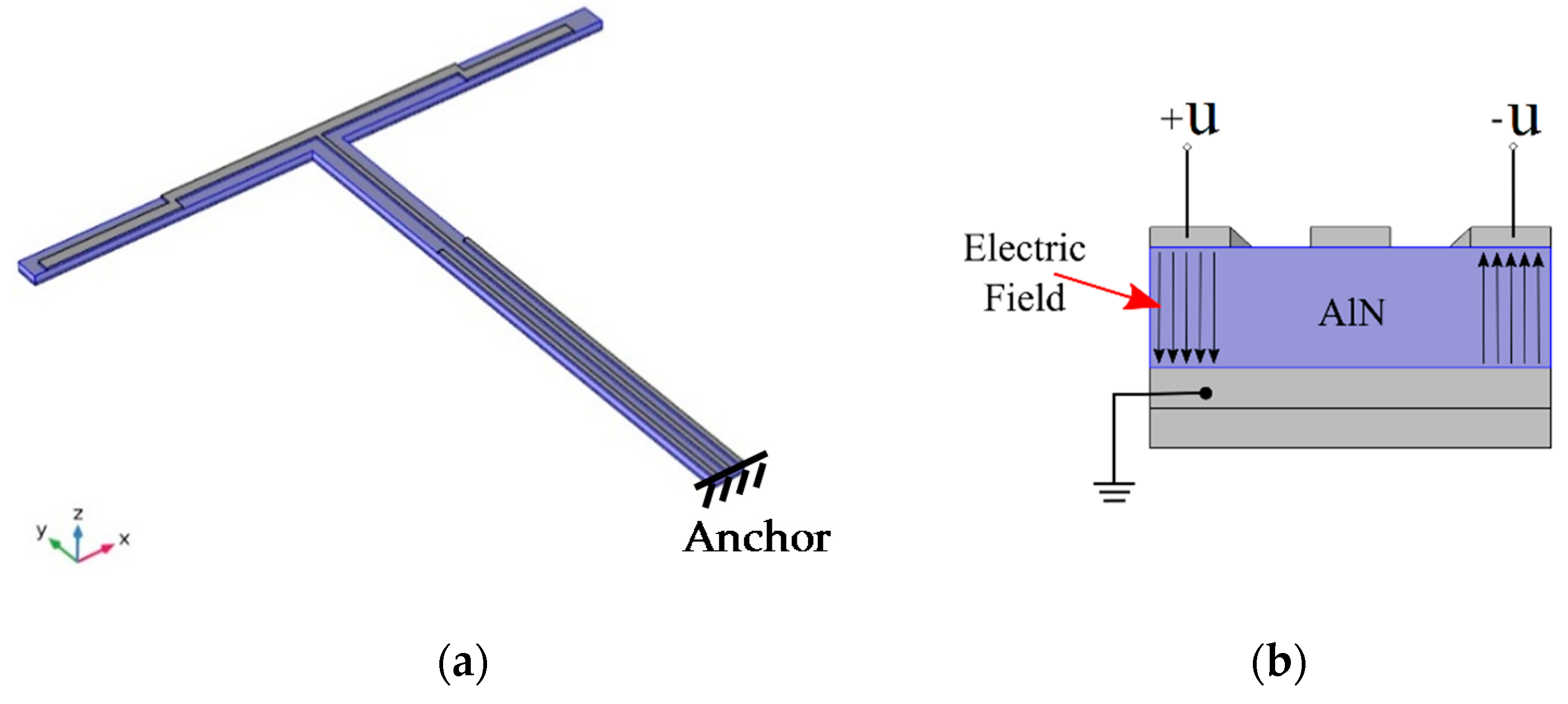
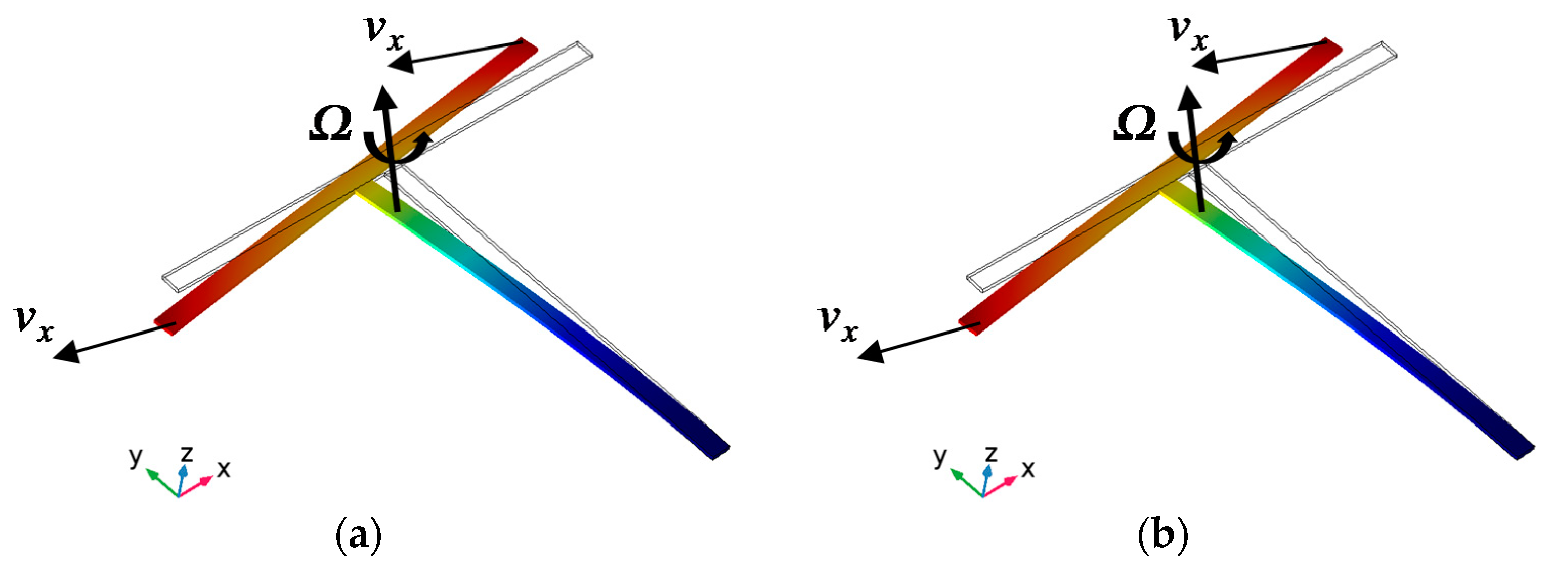
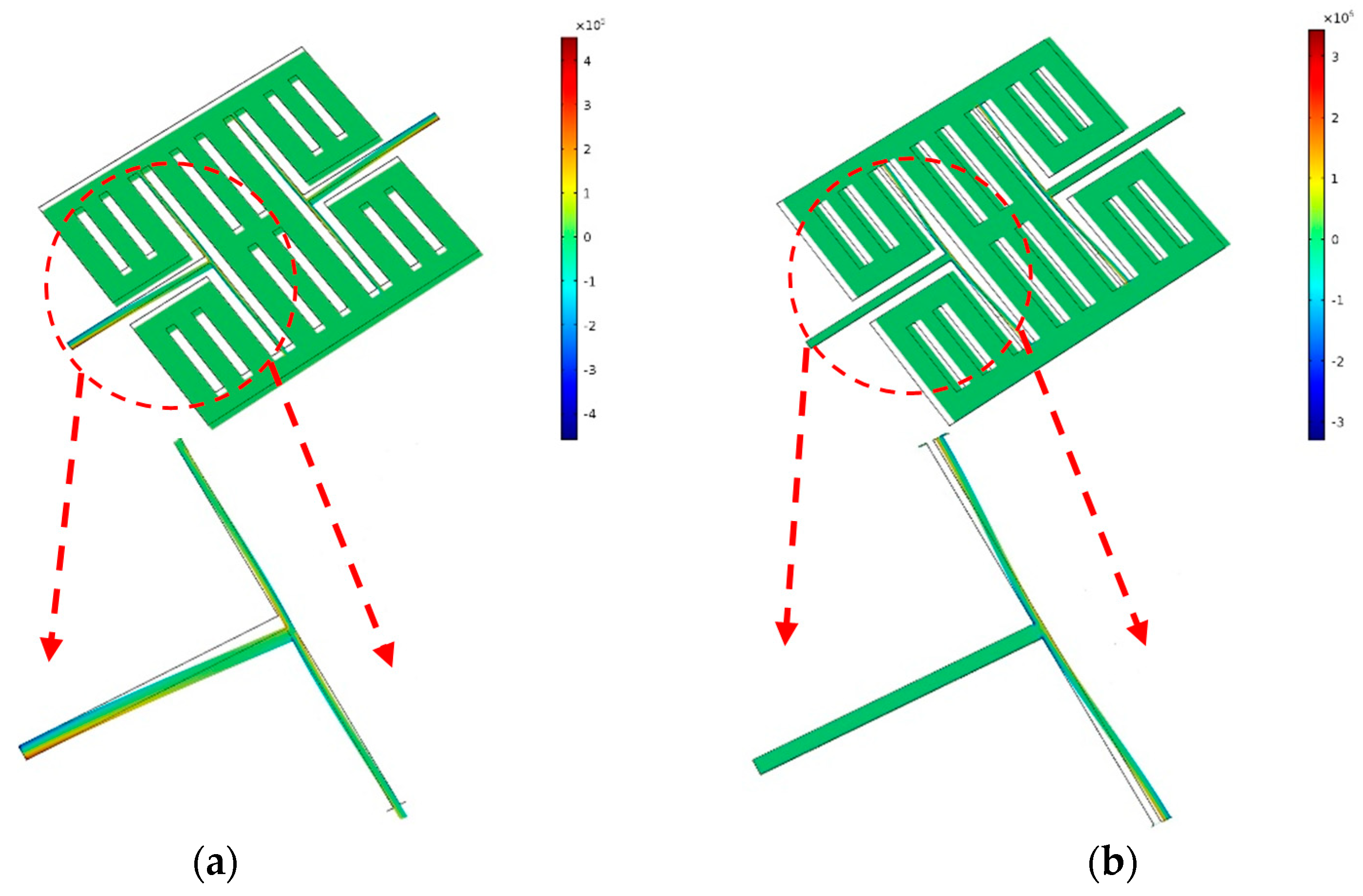
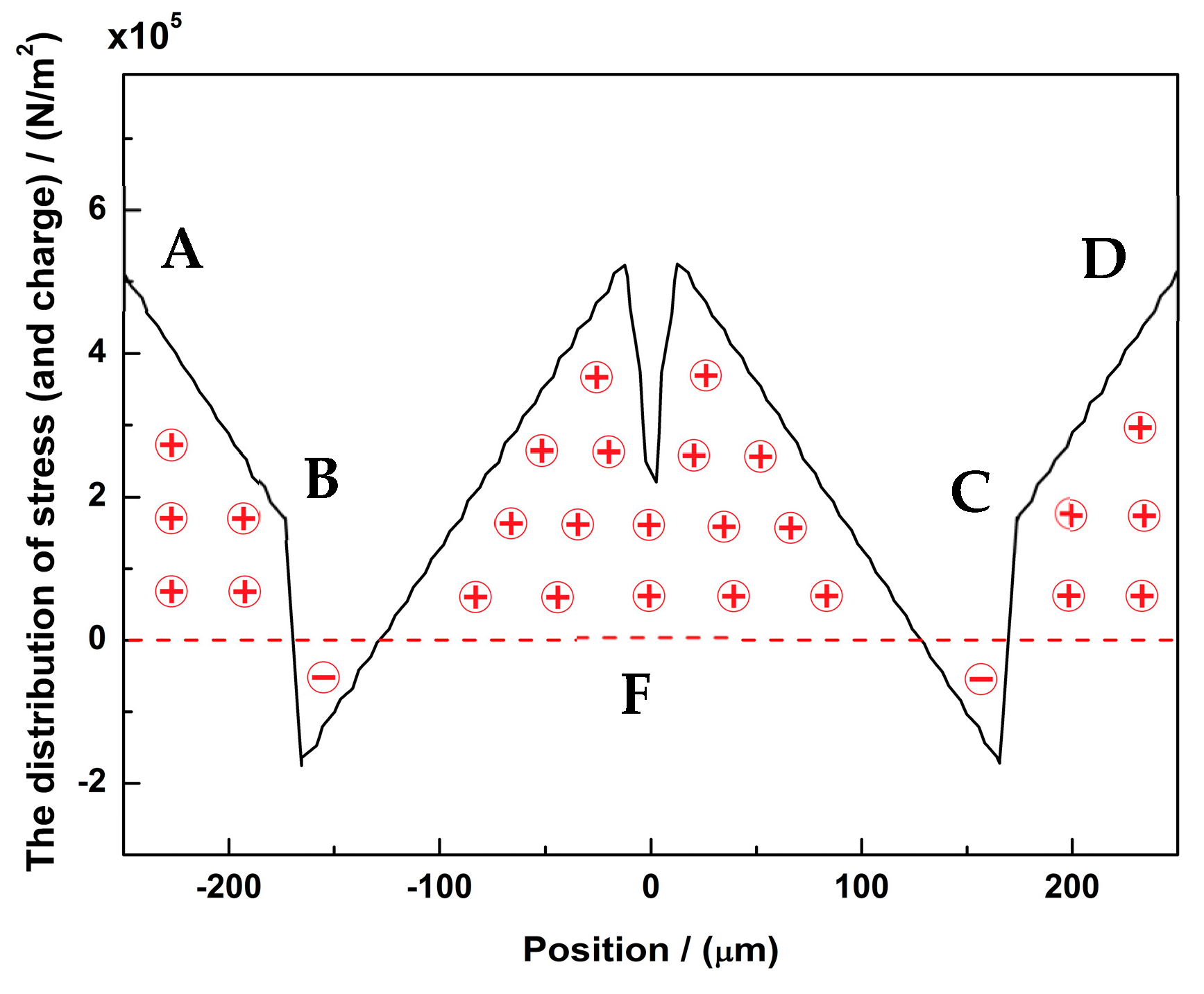
2. Design
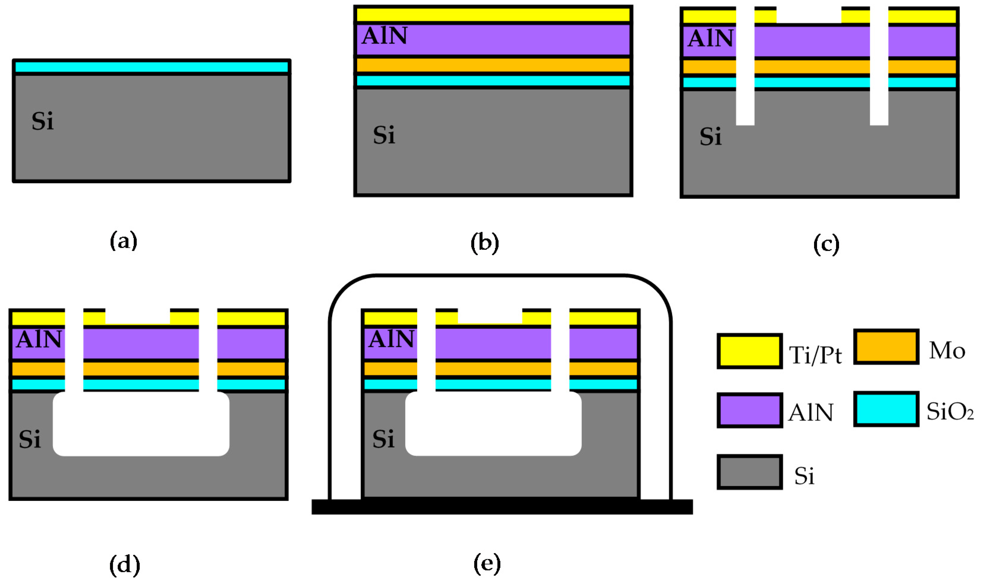
3. Fabrication Process
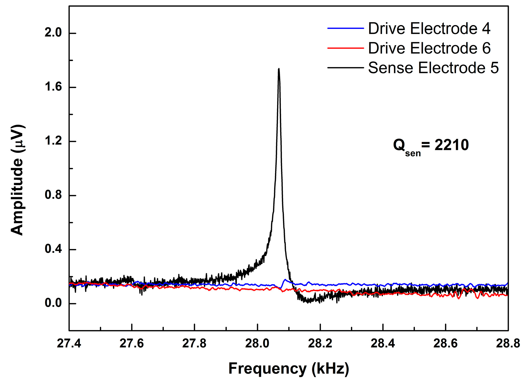
4. Results and Discussion
5. Conclusions
Author Contributions
Funding
Conflicts of Interest
References
- Wang, S.; Deng, Z.; Yin, G. An Accurate GPS-IMU/DR Data Fusion Method for Driverless Car Based on a Set of Predictive Models and Grid Constraints. Sensors 2016, 16, 280. [Google Scholar] [CrossRef] [PubMed]
- Guo, H.; Huang, H.; Huang, L.; Sun, Y.-E. Recognizing the Operating Hand and the Hand-Changing Process for User Interface Adjustment on Smartphones. Sensors 2016, 16, 1314. [Google Scholar] [CrossRef] [PubMed]
- Saeedi, S.; El-Sheimy, N. Activity Recognition Using Fusion of Low-Cost Sensors on a Smartphone for Mobile Navigation Application. Micromachines 2015, 6, 1100–1134. [Google Scholar] [CrossRef]
- Sofla, M.S.; Parsa, M.; Golshanian, H. Stabilizing a camera mount using MEMS gyroscope and accelerometer. Trans. Inst. Meas. Control 2016, 38, 1345–1352. [Google Scholar] [CrossRef]
- Xia, D.; Yu, C.; Kong, L. The development of micromachined gyroscope structure and circuitry technology. Sensors 2014, 14, 1394–1473. [Google Scholar] [CrossRef]
- Zhang, T.; Zhou, B.; Yin, P.; Chen, Z.; Zhang, R. Optimal Design of a Center Support Quadruple Mass Gyroscope (CSQMG). Sensors 2016, 16, 613. [Google Scholar] [CrossRef]
- Sharma, A.; Zaman, M.F.; Zucher, M.; Ayazi, F. A 0.1/HR bias drift electronically matched tuning fork microgyroscope. In Proceedings of the 2008 IEEE 21st International Conference on Micro Electro Mechanical Systems, Wuhan, China, 13–17 January 2008; pp. 6–9. [Google Scholar]
- Daruwalla, A.; Wen, H.R.; Mirjalili, R.; Ayazi, F. Epitaxially grown thick polysilicon for BAW disk resonator gyroscopes with very low dissipation. In Proceedings of the 2018 IEEE Micro Electro Mechanical Systems, Belfast, UK, 21–25 January 2018; pp. 1008–1011. [Google Scholar]
- Cao, H.; Li, H.; Kou, Z.; Shi, Y.; Tang, J.; Ma, Z. Optimization and Experimentation of Dual-Mass MEMS Gyroscope Quadrature Error Correction Methods. Sensors 2016, 16, 71. [Google Scholar] [CrossRef]
- Yang, B.; Wang, X.; Deng, Y.; Hu, D. Mechanical Coupling Error Suppression Technology for an Improved Decoupled Dual-Mass Micro-Gyroscope. Sensors 2016, 16, 503. [Google Scholar] [CrossRef]
- Alper, S.E.; Temiz, Y.; Akin, T. A Compact Angular Rate Sensor System Using a Fully Decoupled Silicon-on-Glass MEMS Gyroscope. J. Microelectromech. Syst. 2008, 17, 1418–1429. [Google Scholar] [CrossRef]
- Palaniapan, M.; Howe, R.T.; Yasaitis, J. Performance comparison of integrated z-axis frame microgyroscopes. In Proceedings of the Sixteenth Annual International Conference on Micro Electro Mechanical Systems, Kyoto, Japan, 19–23 January 2003; pp. 482–485. [Google Scholar]
- Ayazi, F.; Najafi, K. A HARPSS polysilicon vibrating ring gyroscope. J. Microelectromech. Syst. 2001, 10, 169–179. [Google Scholar] [CrossRef]
- Sun, B.; Wang, S.; Li, H.; He, X. Decoupling Control of Micromachined Spinning-Rotor Gyroscope with Electrostatic Suspension. Sensors 2016, 16, 1747. [Google Scholar] [CrossRef]
- Geiger, W.; Butt, W.U.; Gaißer, A.; Frech, J.; Braxmaier, M.; Link, T. Decoupled microgyros and the design principle DAVED. Sens. Actuators A Phys. 2002, 95, 239–249. [Google Scholar] [CrossRef]
- Alper, S.E.; Akin, T. A single-crystal silicon symmetrical and decoupled MEMS gyroscope on an insulating substrate. J. Microelectromech. Syst. 2005, 14, 707–717. [Google Scholar] [CrossRef]
- Xia, D.; Kong, L.; Gao, H. A Mode Matched Triaxial Vibratory Wheel Gyroscope with Fully Decoupled Structure. Sensors 2015, 15, 28979–29002. [Google Scholar] [CrossRef]
- Goericke, F.T.; Vigevani, G.; Izyumin, I.I.; Boser, B.E.; Pisano, A.P. Novel thin-film piezoelectric aluminum nitride rate gyroscope. In Proceedings of the 2012 IEEE International Ultrasonics Symposium, Dresden, Germany, 7–10 October 2012; pp. 1067–1070. [Google Scholar]
- Hodjat-Shamami, M.; Norouzpour-Shirazi, A.; Ayazi, F. Eigenmode operation as a quadrature error cancellation technique for piezoelectric resonant gyroscopes. In Proceedings of the 2017 IEEE 30th International Conference on Micro Electro Mechanical Systems (MEMS), Las Vegas, NV, USA, 22–26 January 2017; pp. 1107–1110. [Google Scholar]
- Guërard, J.; Janiaud, D.; Taïbi, R.; Lévy, R.; Traon, O.L. Quartz structures for Coriolis Vibrating Gyroscopes. In Proceedings of the 2014 International Symposium on Inertial Sensors and Systems (ISISS), Laguna Beach, CA, USA, 25–26 February 2014; pp. 1–4. [Google Scholar]
- Vigevani, G.; Goericke, F.T.; Izyumin, I.I.; Boser, B.E.; Pisano, A.P. Electrode design and coupling optimization of Aluminum Nitride DETF. In Proceedings of the 2011 IEEE International Ultrasonics Symposium, Orlando, FL, USA, 18–21 October 2011; pp. 1731–1734. [Google Scholar]
- Alcheikh, N.; Tella, S.A.; Younis, M.I. An investigation into the mechanical behavior of multi- input and multi-output MEMS resonators. Sens. Actuators A Phys. 2018, 280, 309–318. [Google Scholar] [CrossRef]
- Wang, X.; Huan, R.; Pu, D.; Wei, X. Effect of nonlinearity and axial force on frequency drift of a T-shaped tuning fork micro-resonator. J. Micromech. Microeng. 2018, 28, 125012. [Google Scholar] [CrossRef]
- Yang, J.; Si, C.W.; Yang, F.; Han, G.W.; Ning, J.; Yang, F.H. Design and Simulation of A Novel Piezoelectric AlN-Si Cantilever Gyroscope. Micromachines 2018, 9, 81. [Google Scholar] [CrossRef]
- Iriarte, G.F.; Bjurstrom, J.; Westlinder, J.; Engelmark, F.; Katardjiev, I.V. Synthesis of c-axis oriented AlN thin films on metal layers: Al, Mo, Ti, TiN and Ni. In Proceedings of the 2002 IEEE Ultrasonics Symposium, Munich, Germany, 8–11 October 2002; Volume 1, pp. 311–315. [Google Scholar]
- Chen, L.X.; Liu, H.; Liu, S.; Li, C.M.; Wang, Y.C.; An, K. Growth of high quality AlN films on CVD diamond by RF reactive magnetron sputtering. Appl. Surf. Sci. 2018, 431, 152–159. [Google Scholar] [CrossRef]
- Martin, F.; Muralt, P.; Dubois, M.A.; Pezous, A. Thickness dependence of the properties of highly c-axis textured AlN thin films. J. Vac. Sci. Technol. A Vac. Surf. Film. 2004, 22, 361–365. [Google Scholar] [CrossRef]
- Yang, J.; Si, C.W.; Han, G.W.; Zhang, M.; Ma, L.H.; Zhao, Y.M. Researching the Aluminum Nitride Etching Process for Application in MEMS Resonators. Micromachines 2015, 6, 281–290. [Google Scholar] [CrossRef]
- Lin, H.; Wang, N.; Yang, Y.J. Orthogonal Coupling Analysis of a Fully Decoupled Silicon MEMS Gyroscope. Micronanoelectron. Technol. 2018, 55, 38–44. [Google Scholar]
- Jiang, S.D. Theoretical Research on Sensitive Structure of Silicon Micromachined Gyroscope. Ph.D. Thesis, Nanjing University of Science & Technology, Nanjing, China, 2015. [Google Scholar]


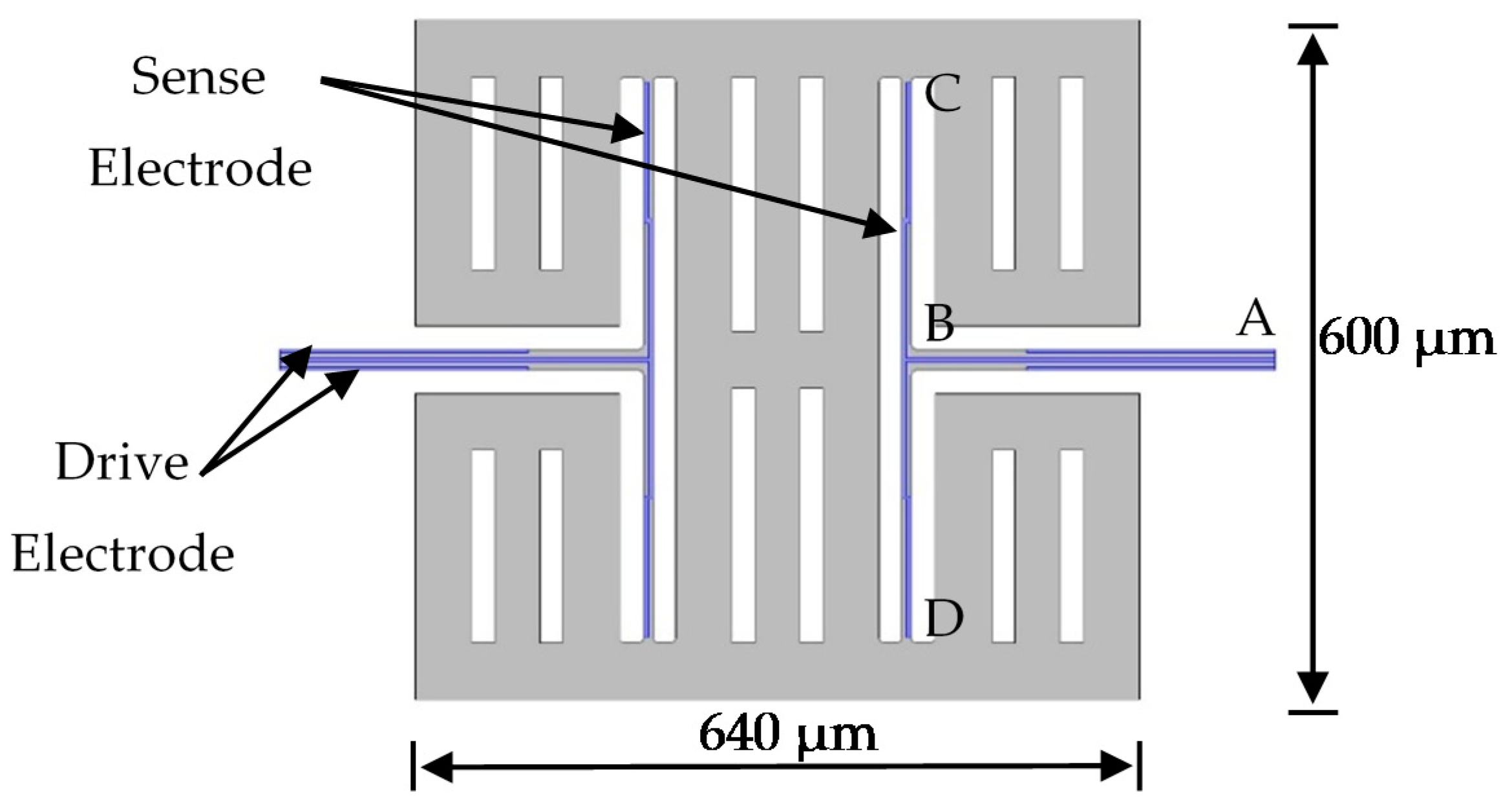
| Parameters | Dimensions |
|---|---|
| Length of T-shape beam (AB) | 322 μm |
| Width of T-shape beam (AB) | 18 μm |
| Length of T-shape beam (CD) | 500 μm |
| Width of T-shape beam (CD) | 8 μm |
| Length of drive electrode | 220 μm |
| Width of drive electrode | 4.5 μm |
| Width of sense electrode | 4 μm |
| Length of the proof mass | 640 μm |
| Width of the proof mass | 600 μm |
© 2019 by the authors. Licensee MDPI, Basel, Switzerland. This article is an open access article distributed under the terms and conditions of the Creative Commons Attribution (CC BY) license (http://creativecommons.org/licenses/by/4.0/).
Share and Cite
Yang, J.; Si, C.; Han, G.; Zhang, M.; Ning, J.; Zhao, Y.; Yang, F.; Wang, X. A Decoupling Design with T-Shape Structure for the Aluminum Nitride Gyroscope. Micromachines 2019, 10, 244. https://doi.org/10.3390/mi10040244
Yang J, Si C, Han G, Zhang M, Ning J, Zhao Y, Yang F, Wang X. A Decoupling Design with T-Shape Structure for the Aluminum Nitride Gyroscope. Micromachines. 2019; 10(4):244. https://doi.org/10.3390/mi10040244
Chicago/Turabian StyleYang, Jian, Chaowei Si, Guowei Han, Meng Zhang, Jin Ning, Yongmei Zhao, Fuhua Yang, and Xiaodong Wang. 2019. "A Decoupling Design with T-Shape Structure for the Aluminum Nitride Gyroscope" Micromachines 10, no. 4: 244. https://doi.org/10.3390/mi10040244
APA StyleYang, J., Si, C., Han, G., Zhang, M., Ning, J., Zhao, Y., Yang, F., & Wang, X. (2019). A Decoupling Design with T-Shape Structure for the Aluminum Nitride Gyroscope. Micromachines, 10(4), 244. https://doi.org/10.3390/mi10040244