The Effects of Cold Arm Width and Metal Deposition on the Performance of a U-Beam Electrothermal MEMS Microgripper for Biomedical Applications


Abstract
1. Introduction
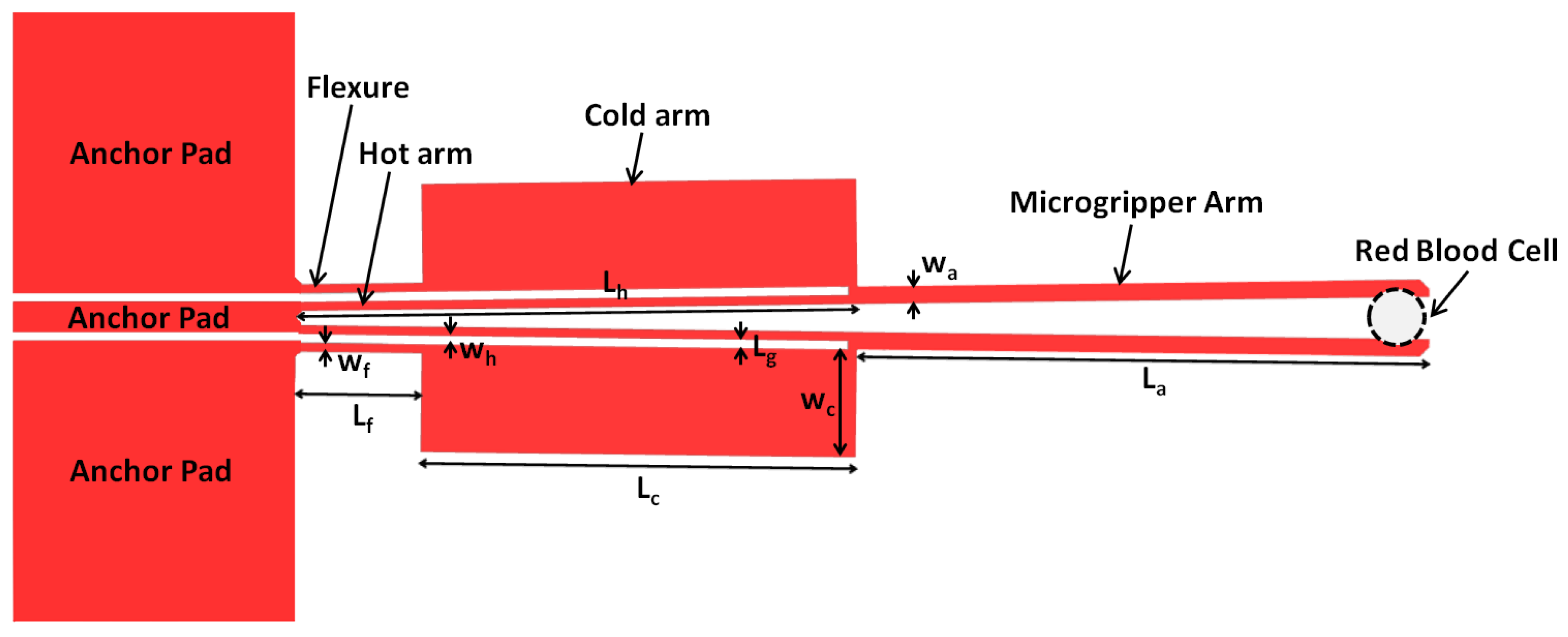
2. The ‘Hot and Cold Arm’ Microgripper Design
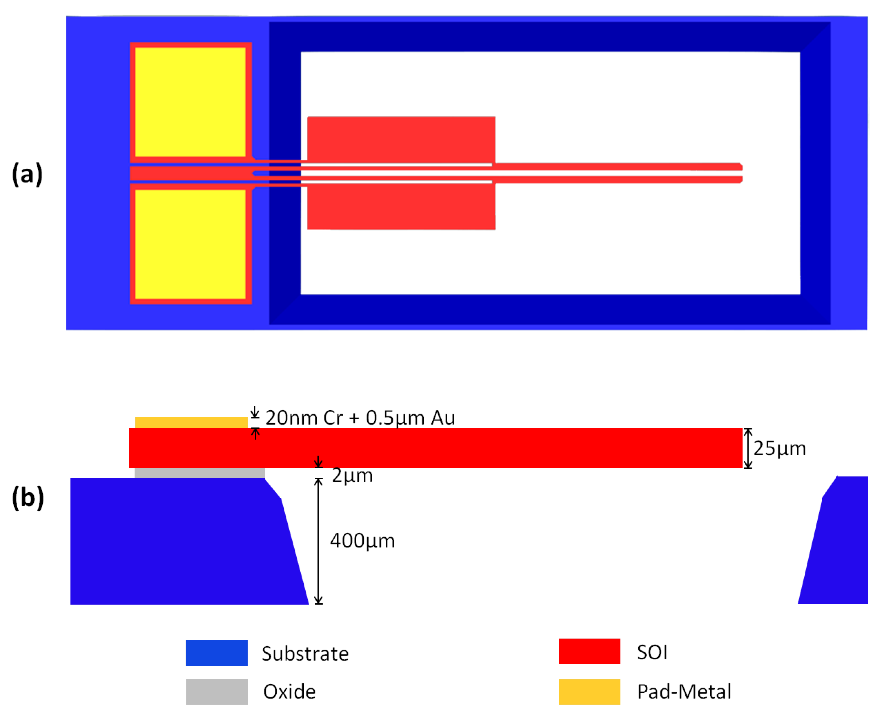
3. SOIMUMPs™ Fabrication Technology
4. Numerical Model
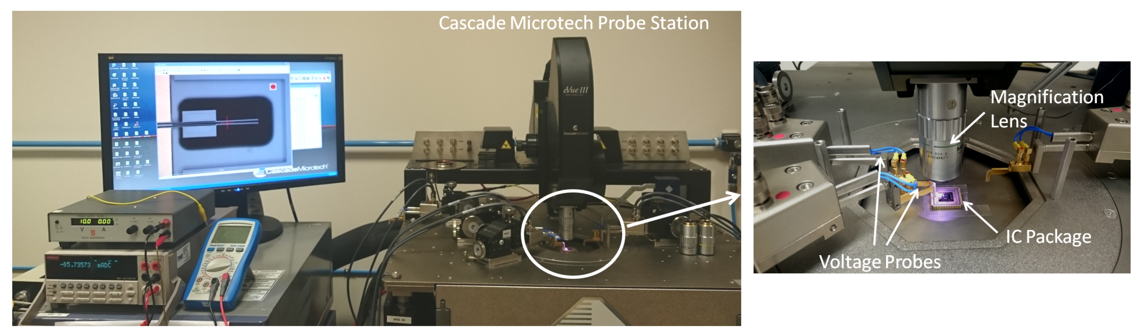
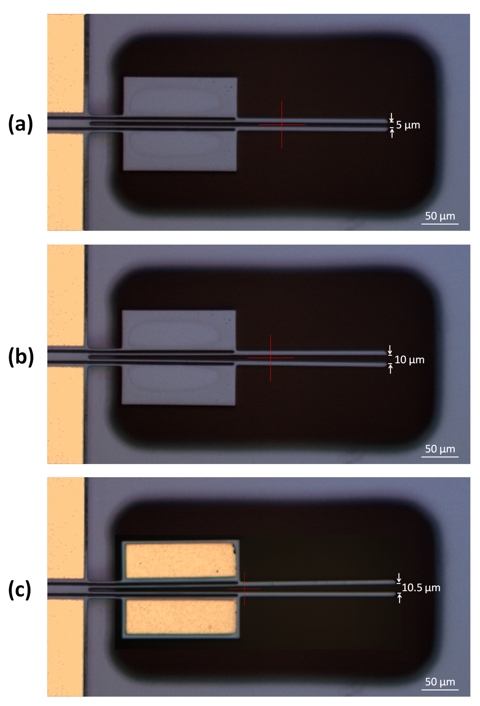
5. Experimental Setup
6. Results and Discussion
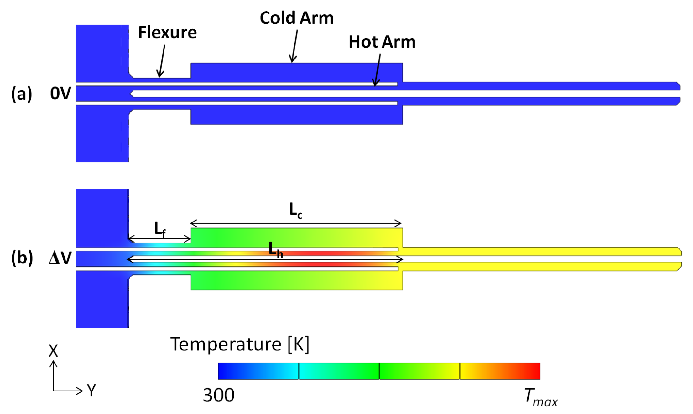
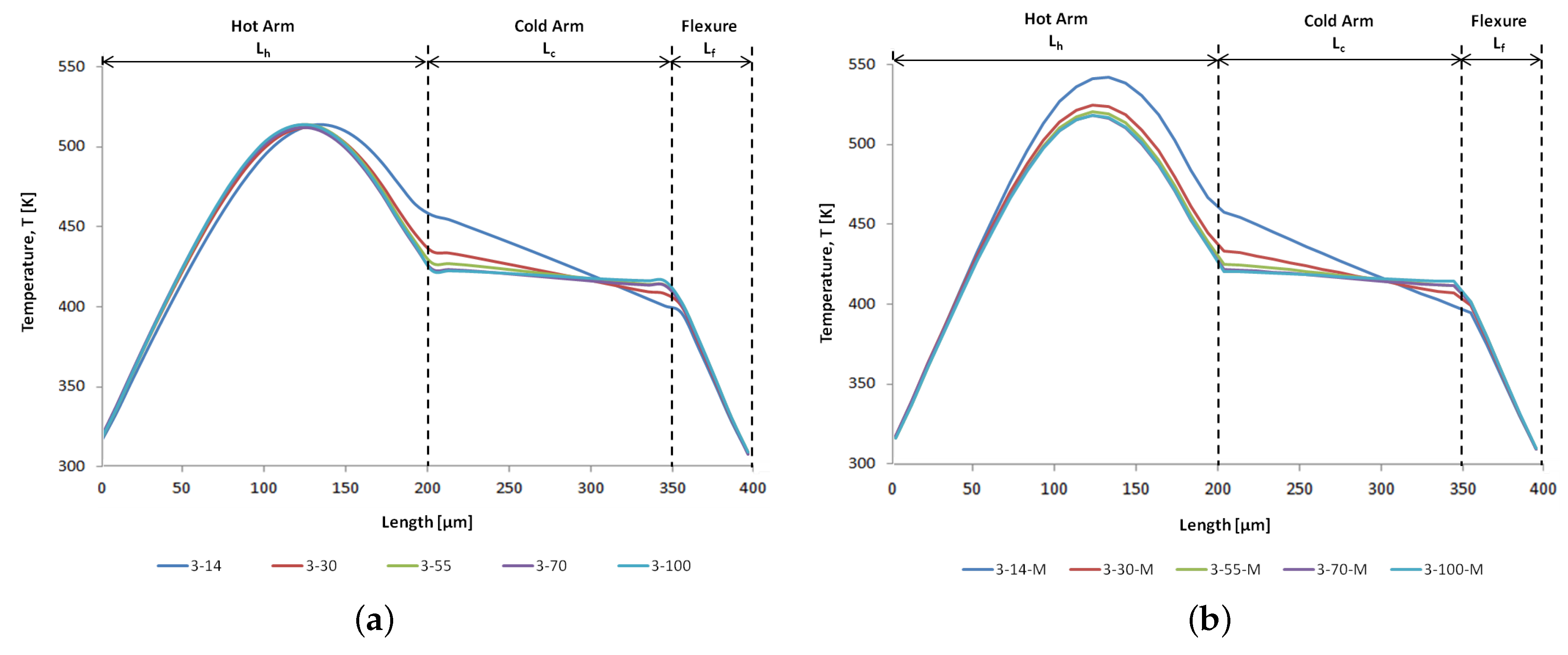
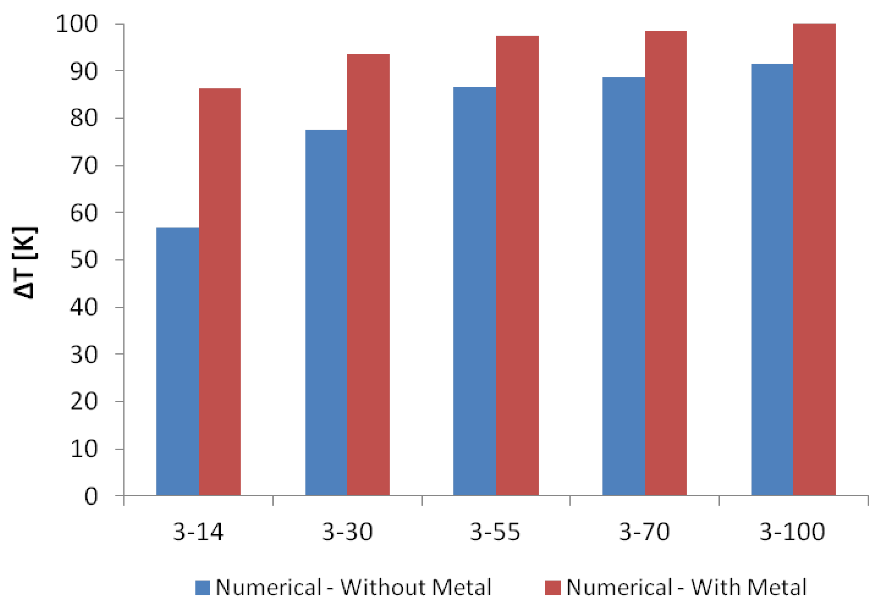
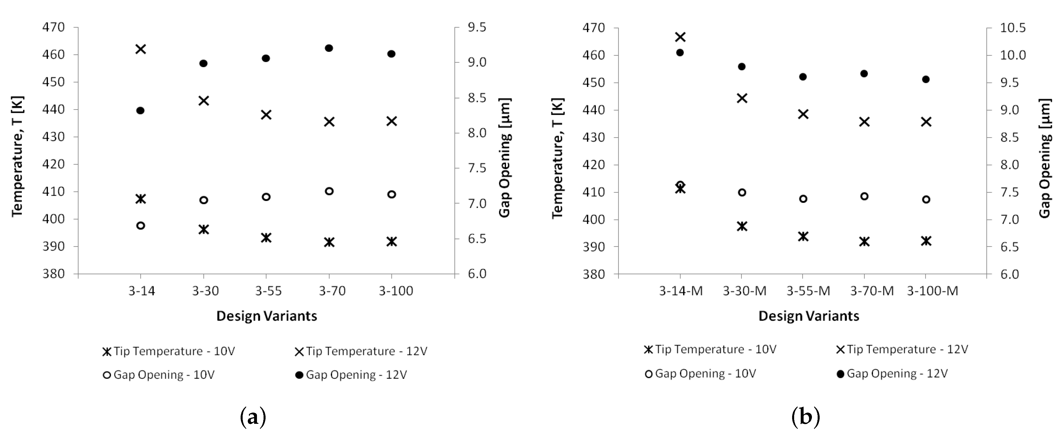
6.1. Thermal Analyses
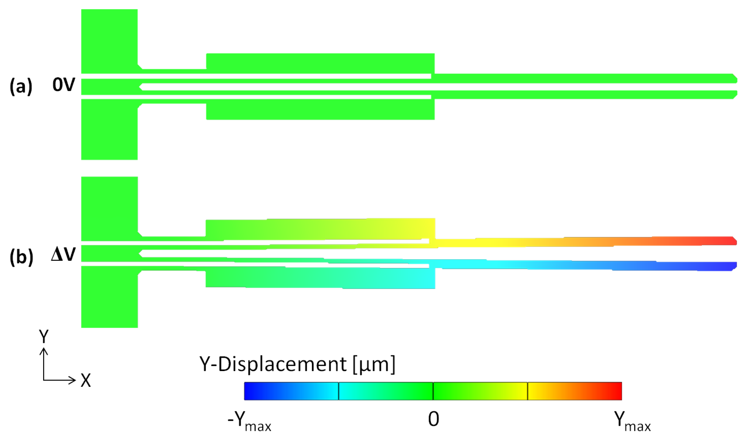
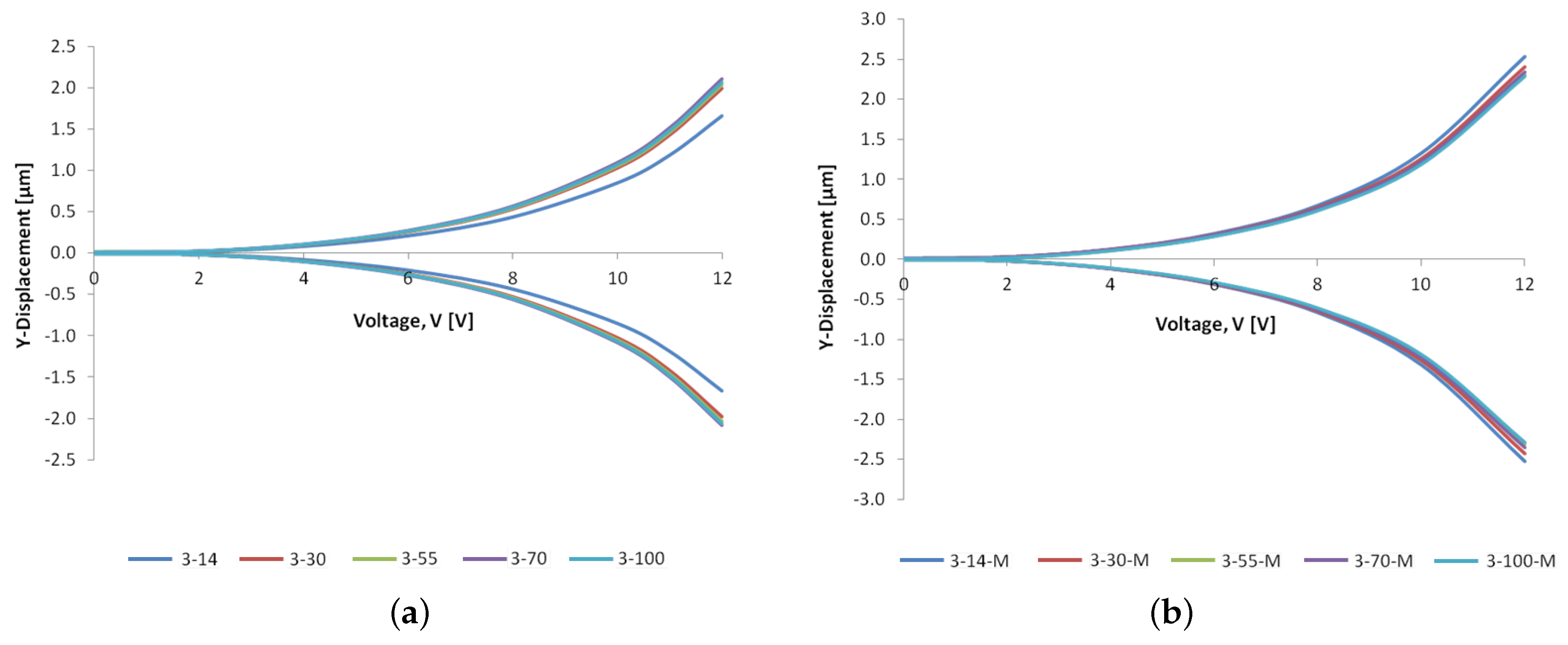
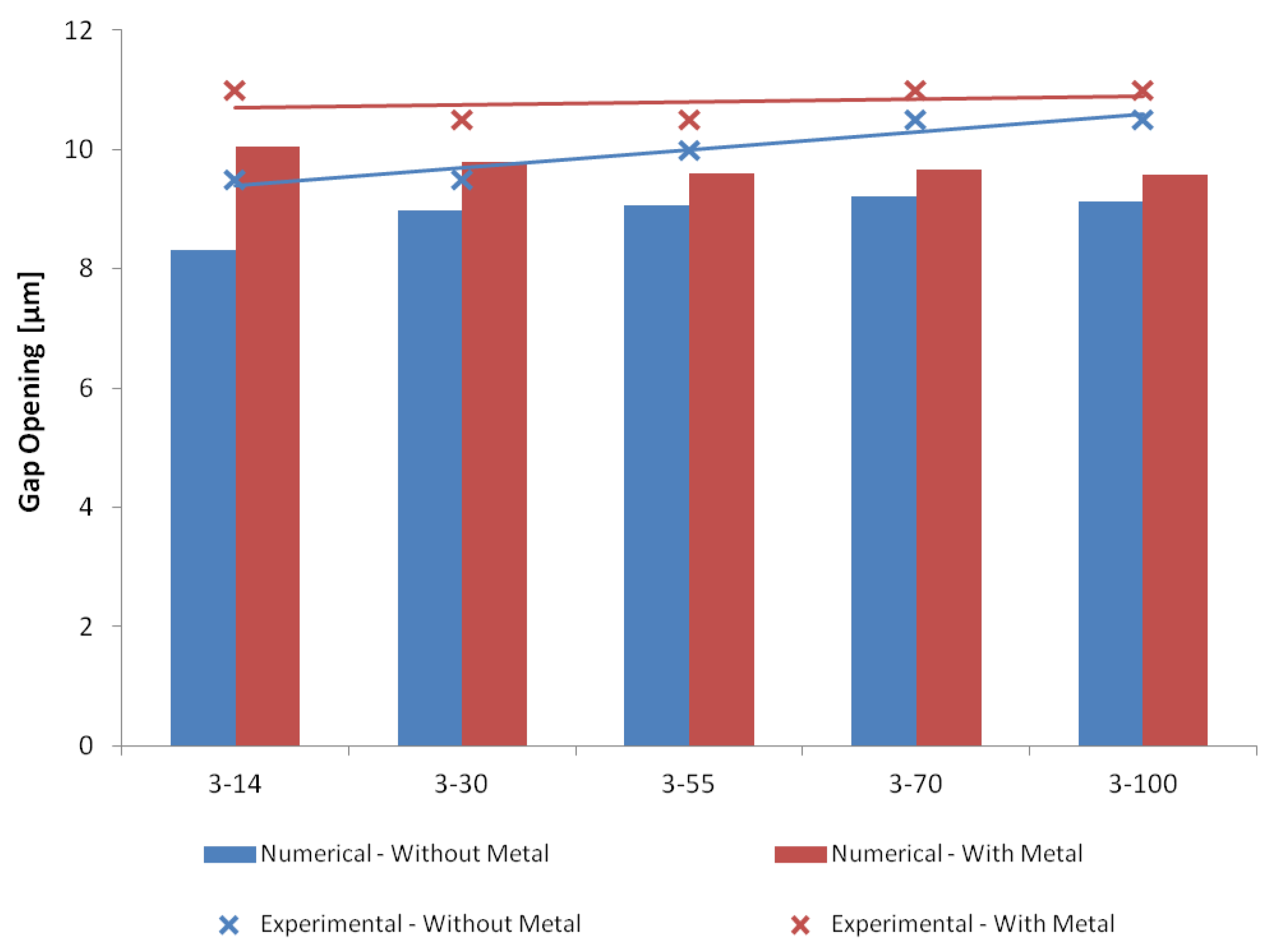
6.2. Structural Analyses
7. Conclusions
Author Contributions
Funding
Acknowledgments
Conflicts of Interest
References
- Ivanova, K.; Ivanov, T.; Badar, A.; Volland, B.E.; Rangelow, I.W.; Andrijasevic, D.; Sümecz, F.; Fischer, S.; Spitzbart, M.; Brenner, W.; et al. Thermally driven microgripper as a tool for micro assembly. Microelectron. Eng. 2006, 83, 1393–1395. [Google Scholar] [CrossRef]
- Zhang, Y.; Chen, B.K.; Liu, X.; Sun, Y. Autonomous robotic pick-and-place of microobjects. IEEE Trans. Robot. 2010, 26, 200–207. [Google Scholar] [CrossRef]
- Zhang, R.; Chu, J.; Wang, H.; Chen, Z. A multipurpose electrothermal microgripper for biological micro-manipulation. Microsyst. Tech. 2013, 19, 89–97. [Google Scholar] [CrossRef]
- Di Giamberardino, P.; Bagolini, A.; Bellutti, P.; Rudas, I.J.; Verotti, M.; Botta, F.; Belfiore, N.P. New MEMS tweezers for the viscoelastic characterization of soft materials at the microscale. Micromachines 2017, 9, 15. [Google Scholar] [CrossRef] [PubMed]
- Kim, K.; Liu, X.; Zhang, Y.; Cheng, J.; Yu, W.X.; Sun, Y. Elastic and viscoelastic characterization of microcapsules for drug delivery using a force-feedback MEMS microgripper. Biomed. Microdevices 2009, 11, 421–427. [Google Scholar] [CrossRef] [PubMed]
- Iamoni, S.; Somà, A. Design of an electro-thermally actuated cell microgripper. Microsyst. Technol. 2014, 20, 869–877. [Google Scholar] [CrossRef]
- Potrich, C.; Lunelli, L.; Bagolini, A.; Bellutti, P.; Pederzolli, C.; Verotti, M.; Belfiore, N.P. Innovative Silicon Microgrippers for Biomedical Applications: Design, Mechanical Simulation and Evaluation of Protein Fouling. Actuators 2018, 2, 12. [Google Scholar] [CrossRef]
- Verotti, M.; Dochshanov, A.; Belfiore, N.P. A comprehensive survey on microgrippers design: Mechanical structure. J. Mech. Des. 2017, 139, 060801. [Google Scholar] [CrossRef]
- Karbasi, S.M.; Shamshirsaz, M.; Naraghi, M.; Maroufi, M. Optimal design analysis of electrothermally driven microactuators. Microsyst. Technol. 2010, 16, 1065–1071. [Google Scholar] [CrossRef]
- Nguyen, N.-T.; Ho, S.-S.; Low, C.L. A polymeric microgripper with integrated thermal actuators. J. Microelectromech. Syst. 2004, 14, 969–974. [Google Scholar] [CrossRef]
- Cauchi, M.; Grech, I.; Mallia, B.; Mollicone, P.; Sammut, N. Analytical, Numerical and Experimental Study of a Horizontal Electrothermal MEMS Microgripper for the Deformability Characterisation of Human Red Blood Cells. Micromachines 2018, 9, 108. [Google Scholar] [CrossRef] [PubMed]
- Yang, S.; Xu, Q. A review on actuation and sensing techniques for MEMS-based microgrippers. J. Micro-Bio Robot. 2017, 13, 1–14. [Google Scholar] [CrossRef]
- Dochshanov, A.; Verotti, M.; Belfiore, N.P. A comprehensive survey on microgrippers design: Operational strategy. J. Mech. Des. 2017, 139, 070801. [Google Scholar] [CrossRef]
- Kim, C.-J.; Pisano, A.P.; Muller, R.S. Silicon-processed overhanging microgripper. J. Microelectromech. Syst. 1992, 1, 31–36. [Google Scholar] [CrossRef]
- Bagolini, A.; Ronchin, S.; Bellutti, P.; Chistè, M.; Verotti, M.; Belfiore, N.P. Fabrication of novel MEMS microgrippers by deep reactive ion etching with metal hard mask. J. Microelectromech. Syst. 2017, 26, 7920329. [Google Scholar] [CrossRef]
- Cauchi, M.; Grech, I.; Mallia, B.; Mollicone, P.; Sammut, N. The Effects of Structure Thickness, Air Gap Thickness and Silicon Type on the Performance of a Horizontal Electrothermal MEMS Microgripper. Actuators 2018, 7, 38. [Google Scholar] [CrossRef]
- Feng, Y.-Y.; Chen, S.-J.; Hsieh, P.-H.; Chu, W.-T. Fabrication of an electro-thermal micro-gripper with elliptical cross-sections using silver-nickel composite ink. Sens. Actuators A Phys. 2016, 245, 106–112. [Google Scholar] [CrossRef]
- Chronis, N.; Lee, L.P. Electrothermally activated SU-8 microgripper for single cell manipulation in solution. J. Microelectromech. Syst. 2005, 14, 857–863. [Google Scholar] [CrossRef]
- Guckel, H.; Klein, J.; Christenson, T.; Skrobis, K.; Laudon, M.; Lovell, E.G. Thermo-magnetic metal flexure actuators. In Proceedings of the Technical Digest IEEE Solid-State Sensor and Actuator Workshop, Hilton Head Island, SC, USA, 22–25 June 1992; pp. 73–75. [Google Scholar]
- Comtois, J.H.; Bright, V.M. Applications for surface-micromachined polysilicon thermal actuators and arrays. Sens. Actuators A Phys. 1997, 58, 19–25. [Google Scholar] [CrossRef]
- Cauchi, M.; Mollicone, P.; Grech, I.; Mallia, B.; Portelli, B.; Sammut, N. Design and fabrication considerations, numerical modelling, and testing of a MEMS microgripper. In Proceedings of the 2018 Symposium on Design, Test, Integration and Packaging of MEMS and MOEMS (DTIP), Rome, Italy, 22–25 May 2018. [Google Scholar]
- Hannon, B.; Ruth, M. Malaria and Sickle Cell Anemia. In Dynamic Modeling of Diseases and Pests; Springer: New York, NY, USA, 2009; pp. 63–81. [Google Scholar]
- Tomaiuolo, G. Biomechanical properties of red blood cells in health and disease towards microfluidics. Biomicrofluidics 2014, 8, 051501. [Google Scholar] [CrossRef] [PubMed]
- Zaitsev, B.N. Blood Cells Study. NT-MDT Spectrum Instruments; State Research Center of Virology and Biotechnology VECTOR: Koltsovo, Novosibirsk Oblast, Russia, 2015. [Google Scholar]
- BruceBlaus, Sickle Cell Anemia, Medical gallery of Blausen Medical, WikiJournal of Medicine, Wikimedia Commons, CC BY-SA 4.0 License. 2015. Available online: https://commons.m.wikimedia (accessed on 17 December 2018).
- Cauchi, M.; Mollicone, P.; Grech, I.; Mallia, B.; Sammut, N. Design and analysis of a MEMS-based electrothermal microgripper. In Proceedings of the International CAE Conference 2016, Parma, Italy, 17–18 October 2016. [Google Scholar]
- Jia, Y.; Xu, Q. MEMS microgripper actuators and sensors: The state-of-the-art survey. Recent Patents Mech. Eng. 2013, 6, 132–142. [Google Scholar] [CrossRef]
- Burns, D.M.; Bright, V.M. Design and performance of a double hot arm polysilicon thermal actuator. In Proceedings of the Society of Photo-Optical Instrumentation Engineers (SPIE) 3224, Micromachined Devices and Components III, Austin, TX, USA, 29–30 September 1997; pp. 296–307. [Google Scholar]
- Yan, D.; Khajepour, A.; Mansour, R. Modeling of two-hot-arm horizontal thermal actuator. J. Micromech. Microeng. 2003, 13, 312–322. [Google Scholar] [CrossRef]
- Choi, Y.-S.; Zhang, Y.; Lee, D.-W. A thermal-driven silicon micro XY-stage integrated with piezoresistive sensors for nano-positioning. J. Micromech. Microeng. 2012, 22, 055002. [Google Scholar] [CrossRef]
- Cowen, A.; Hames, G.; Monk, D.; Wilcenski, S.; Hardy, B. SOIMUMPs Design Handbook; MEMSCAP Inc.: Durham, NC, USA, 2011. [Google Scholar]
- Hopcroft, M.A.; Nix, W.D.; Kenny, T.W. What is the Young’s Modulus of silicon? J. Microelectromech. Syst. 2010, 19, 229–238. [Google Scholar] [CrossRef]
- Boyd, E.J.; Uttamchandani, D. Measurement of the anisotropy of Young’s Modulus in single-crystal silicon. J. Microelectromech. Syst. 2012, 21, 243–249. [Google Scholar] [CrossRef]
- Prasad, A.; Venkatesh, K.P.; Pratap, R.; Bhat, N. Improved Design Methodology for the Development of Electrically Actuated MEMS Structures. In Proceedings of the 2014 27th International Conference on VLSI Design and 2014 13th International Conference on Embedded Systems, Mumbai, India, 5–9 January 2014; pp. 459–503. [Google Scholar]


| Parameter | Value (m) |
|---|---|
| Length of hot arm, | 200 |
| Length of cold arm, | 154 |
| Length of flexure, | 46 |
| Length of connector, | 3 |
| Length of gripping arm, | 203 |
| Width of hot arm, | 3 |
| Width of cold arm, | 14, 30, 55, 70, 100 |
| Width of flexure, | 3 |
| Width of gripping arm, | 6 |
| V (V) | Measured Data | Simulated Data | Error | |||||
|---|---|---|---|---|---|---|---|---|
| I (mA) | R (k) | P (mW) | I (mA) | R (k) | P (mW) | R (%) | P (%) | |
| 0.5 | 0.38 | 1.33 | 0.19 | 0.39 | 1.30 | 0.19 | 2.64 | 2.57 |
| 1.0 | 0.73 | 1.38 | 0.73 | 0.77 | 1.30 | 0.77 | 6.47 | 6.07 |
| 1.5 | 1.10 | 1.36 | 1.65 | 1.16 | 1.30 | 1.74 | 5.06 | 4.82 |
| 2.0 | 1.47 | 1.37 | 2.93 | 1.54 | 1.30 | 3.09 | 5.38 | 5.10 |
| 2.5 | 1.82 | 1.37 | 4.55 | 1.93 | 1.30 | 4.82 | 6.03 | 5.68 |
| 3.0 | 2.17 | 1.38 | 6.50 | 2.32 | 1.30 | 6.95 | 6.81 | 6.37 |
| 3.5 | 2.51 | 1.40 | 8.77 | 2.70 | 1.30 | 9.46 | 7.76 | 7.20 |
| 4.0 | 2.84 | 1.41 | 11.35 | 3.09 | 1.30 | 12.35 | 8.83 | 8.11 |
| 4.5 | 3.16 | 1.43 | 14.20 | 3.47 | 1.30 | 15.63 | 10.06 | 9.14 |
| 5.0 | 3.43 | 1.46 | 17.15 | 3.86 | 1.30 | 19.30 | 12.52 | 11.13 |
| 5.5 | 3.72 | 1.48 | 20.48 | 4.25 | 1.30 | 23.35 | 14.03 | 12.30 |
| 6.0 | 4.02 | 1.49 | 24.12 | 4.63 | 1.30 | 27.79 | 15.20 | 13.20 |
| 6.5 | 4.21 | 1.55 | 27.33 | 5.02 | 1.30 | 32.61 | 19.31 | 16.19 |
| 7.0 | 4.35 | 1.61 | 30.44 | 5.40 | 1.30 | 37.82 | 24.27 | 19.53 |
| 7.5 | 4.68 | 1.60 | 35.09 | 5.79 | 1.30 | 43.42 | 23.75 | 19.19 |
| 8.0 | 4.92 | 1.63 | 39.34 | 6.17 | 1.30 | 49.40 | 25.58 | 20.37 |
| 8.5 | 5.06 | 1.68 | 42.97 | 6.56 | 1.30 | 55.77 | 29.79 | 22.95 |
| 9.0 | 5.27 | 1.71 | 47.39 | 6.95 | 1.30 | 62.52 | 31.94 | 24.21 |
| 9.5 | 5.44 | 1.75 | 51.66 | 7.33 | 1.30 | 69.66 | 34.84 | 25.84 |
| 10.0 | 5.60 | 1.79 | 55.97 | 7.72 | 1.30 | 77.19 | 37.91 | 27.49 |
| 10.5 | 5.73 | 1.83 | 60.17 | 8.10 | 1.30 | 85.10 | 41.44 | 29.30 |
| 11.0 | 5.85 | 1.88 | 64.35 | 8.49 | 1.30 | 93.40 | 45.14 | 31.10 |
| 11.5 | 6.00 | 1.92 | 69.00 | 8.88 | 1.30 | 102.08 | 47.94 | 32.41 |
| 12.0 | 6.10 | 1.97 | 73.20 | 9.26 | 1.30 | 111.15 | 51.84 | 34.14 |
| Property | SOI | Pad-Metal |
|---|---|---|
| Density (g/(cm)) | 2.50 | 19.30 |
| Young’s modulus, E (GPa) | = = 169 | 57 |
| = 130 | ||
| Shear modulus, G (GPa) | = = 79.6 | - |
| = 50.9 | ||
| Poisson’s ratio, | = 0.36, = 0.29 | 0.35 |
| = 0.064 | ||
| Specific heat capacity, c (J/kgK) | 712 | 128.7 |
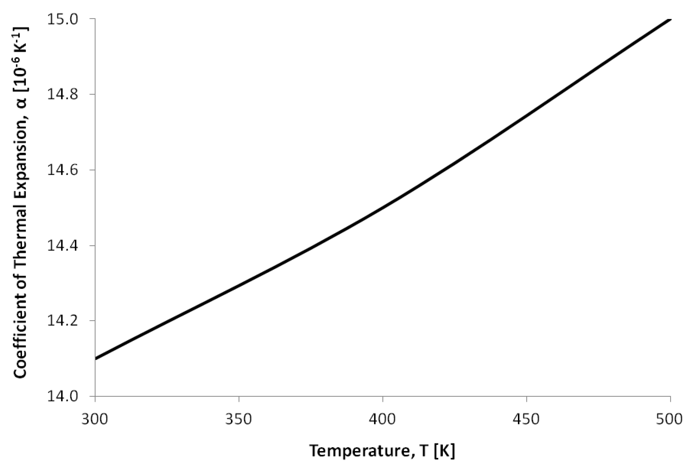
| Thermal expansion coefficient, (K) | Refer to Figure 5 | Refer to Figure 6 |
| Thermal conductivity, k (W/mK) | Refer to Figure 5 | 297 |
| Electrical conductivity (S/mm) | Refer to Figure 5 | 3.496 × 10 |
© 2019 by the authors. Licensee MDPI, Basel, Switzerland. This article is an open access article distributed under the terms and conditions of the Creative Commons Attribution (CC BY) license (http://creativecommons.org/licenses/by/4.0/).
Share and Cite
Cauchi, M.; Grech, I.; Mallia, B.; Mollicone, P.; Sammut, N. The Effects of Cold Arm Width and Metal Deposition on the Performance of a U-Beam Electrothermal MEMS Microgripper for Biomedical Applications. Micromachines 2019, 10, 167. https://doi.org/10.3390/mi10030167
Cauchi M, Grech I, Mallia B, Mollicone P, Sammut N. The Effects of Cold Arm Width and Metal Deposition on the Performance of a U-Beam Electrothermal MEMS Microgripper for Biomedical Applications. Micromachines. 2019; 10(3):167. https://doi.org/10.3390/mi10030167
Chicago/Turabian StyleCauchi, Marija, Ivan Grech, Bertram Mallia, Pierluigi Mollicone, and Nicholas Sammut. 2019. "The Effects of Cold Arm Width and Metal Deposition on the Performance of a U-Beam Electrothermal MEMS Microgripper for Biomedical Applications" Micromachines 10, no. 3: 167. https://doi.org/10.3390/mi10030167
APA StyleCauchi, M., Grech, I., Mallia, B., Mollicone, P., & Sammut, N. (2019). The Effects of Cold Arm Width and Metal Deposition on the Performance of a U-Beam Electrothermal MEMS Microgripper for Biomedical Applications. Micromachines, 10(3), 167. https://doi.org/10.3390/mi10030167