Connector-Free World-to-Chip Interconnection for Microfluidic Devices


Abstract
1. Introduction
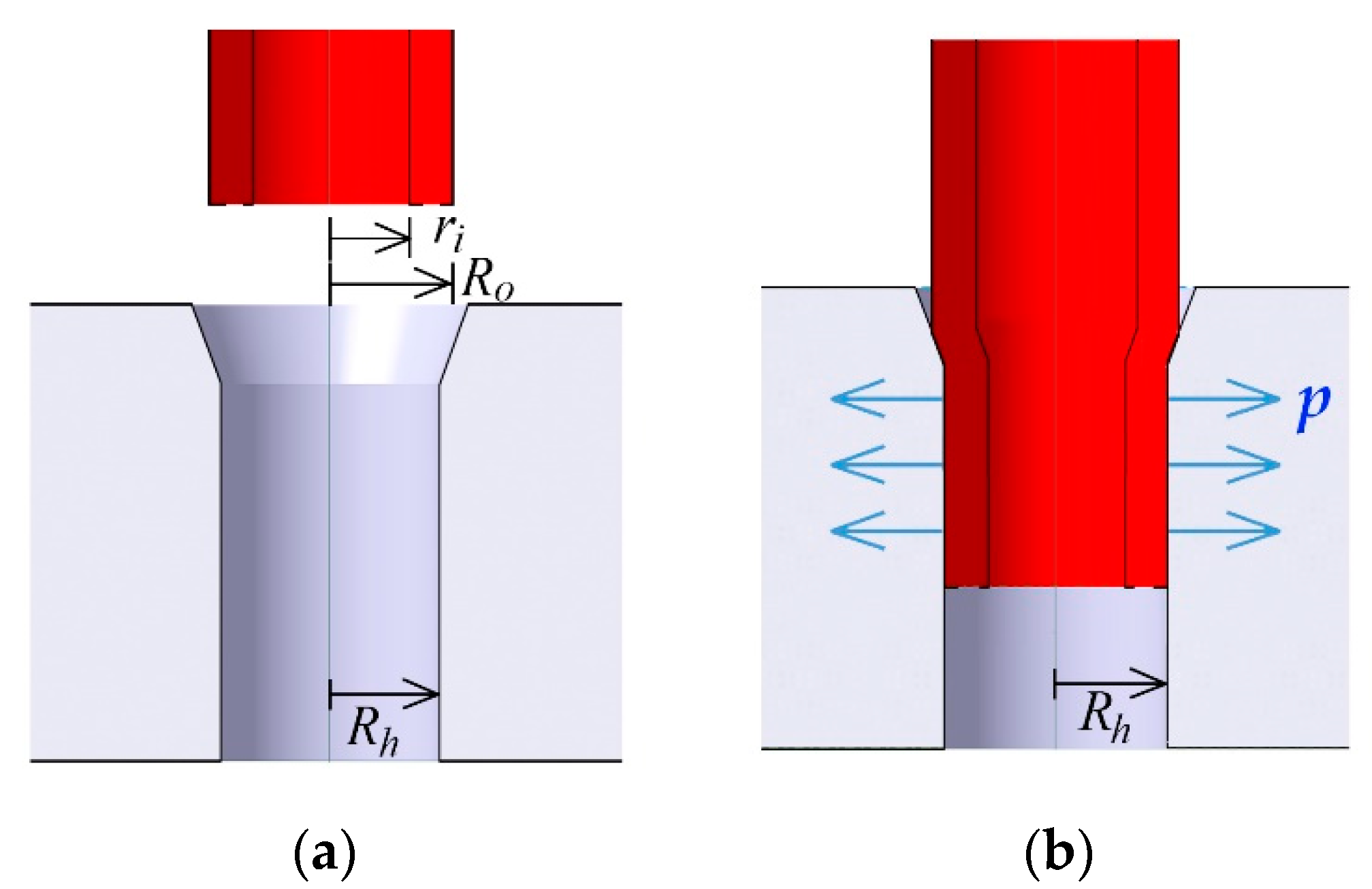
2. Design Concept
3. Results and Discussion
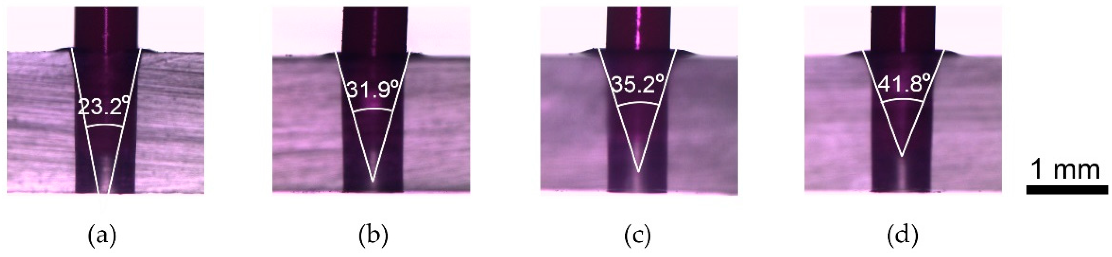
3.1. Interconnection
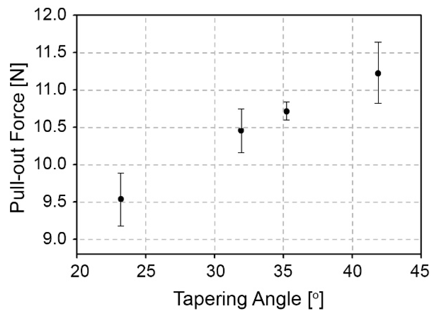
3.2. Interconnection Strength
4. Conclusions
Author Contributions
Funding
Conflicts of Interest
References
- Feng, X.; Du, W.; Luo, Q.; Liu, B.F. Microfluidic chip: Next-generation platform for systems biology. Anal. Chim. Acta 2009, 650, 83–97. [Google Scholar] [CrossRef] [PubMed]
- Manz, A.; Graber, N.; Widmer, H.M. Miniaturized total chemical analysis systems: A novel concept for chemical sensing. Sens. Actuators B Chem. 1990, 1, 244–248. [Google Scholar] [CrossRef]
- Lafleur, J.P.; Jonsson, A.; Senkbeil, S.; Kutter, J.P. Recent advances in lab-on-a-chip for biosensing applications. Biosens. Bioelectron. 2016, 76, 213–233. [Google Scholar] [CrossRef] [PubMed]
- Ensafi, A.A.; Zandi-Atashbar, N.; Rezaei, B.; Ghiaci, M.; Taghizadeh, M. Silver nanoparticles decorated carboxylate functionalized SiO2, new nanocomposites for non-enzymatic detection of glucose and hydrogen peroxide. Electrochim. Acta 2016, 214, 208–216. [Google Scholar] [CrossRef]
- Hu, C.; Munglani, G.; Vogler, H.; Ndinyanka Fabrice, T.; Shamsudhin, N.; Wittel, F.K.; Ringli, C.; Grossniklaus, U.; Herrmann, H.J.; Nelson, B.J. Characterization of size-dependent mechanical properties of tip-growing cells using a lab-on-chip device. Lab Chip 2016, 17, 82–90. [Google Scholar] [CrossRef] [PubMed]
- Temiz, Y.; Lovchik, R.D.; Kaigala, G.V.; Delamarche, E. Lab-on-a-chip devices: How to close and plug the lab? Microelectron. Eng. 2015, 132, 156–175. [Google Scholar] [CrossRef]
- Sabourin, D.; Dufva, M.; Jensen, T.; Kutter, J.; Snakenborg, D. One-step fabrication of microfluidic chips with in-plane, adhesive-free interconnections. J. Micromech. Microeng. 2010, 20, 037001. [Google Scholar] [CrossRef]
- Chiou, C.-H.; Lee, G.-B. Minimal dead-volume connectors for microfluidics using PDMS casting techniques. J. Micromech. Microeng. 2004, 14, 1484–1490. [Google Scholar] [CrossRef]
- Pattekar, A.V.; Kothare, M.V. Novel microfluidic interconnectors for high temperature and pressure applications. J. Micromech. Microeng. 2003, 13, 337–345. [Google Scholar] [CrossRef]
- Sen, A.K.; Darabi, J.; Knapp, D.R. Design, fabrication and test of a microfluidic nebulizer chip for desorption electrospray ionization mass spectrometry. Sens. Actuators B Chem. 2009, 137, 789–796. [Google Scholar] [CrossRef] [PubMed]
- Yuen, P.K. Smartbuild-a truly plug-n-play modular microfluidic system. Lab Chip 2008, 8, 1374–1378. [Google Scholar] [CrossRef] [PubMed]
- Saarela, V.; Franssila, S.; Tuomikoski, S.; Marttila, S.; Östman, P.; Sikanen, T.; Kotiaho, T.; Kostiainen, R. Re-usable multi-inlet pdms fluidic connector. Sens. Actuators B Chem. 2006, 114, 552–557. [Google Scholar] [CrossRef]
- Chen, A.; Pan, T. Fit-to-flow (F2F) interconnects: Universal reversible adhesive-free microfluidic adaptors for lab-on-a-chip systems. Lab Chip 2011, 11, 727–732. [Google Scholar] [CrossRef] [PubMed]
- Sen, A.K.; Darabi, J.; Knapp, D.R. A fluidic interconnection system for polymer-based microfluidic devices. Microsyst. Technol. 2009, 16, 617–623. [Google Scholar] [CrossRef]
- Hou, H.-H.; Wang, Y.-N.; Chang, C.-L.; Yang, R.-J.; Fu, L.-M. Rapid glucose concentration detection utilizing disposable integrated microfluidic chip. Microfluid. Nanofluid. 2011, 11, 479–487. [Google Scholar] [CrossRef]
- Puntambekar, A.; Ahn, C.H. Self-aligning microfluidic interconnects for glass- and plastic-based microfluidic systems. J. Micromech. Microeng. 2002, 12, 35–40. [Google Scholar] [CrossRef]
- Christensen, A.M.; Chang-Yen, D.A.; Gale, B.K. Characterization of interconnects used in pdms microfluidic systems. J. Micromech. Microeng. 2005, 15, 928–934. [Google Scholar] [CrossRef]
- Cooksey, G.A.; Plant, A.L.; Atencia, J. A vacuum manifold for rapid world-to-chip connectivity of complex pdms microdevices. Lab Chip 2009, 9, 1298–1300. [Google Scholar] [CrossRef] [PubMed]
- Hong, J.W.; Studer, V.; Hang, G.; Anderson, W.F.; Quake, S.R. A nanoliter-scale nucleic acid processor with parallel architecture. Nat. Biotechnol. 2004, 22, 435–439. [Google Scholar] [CrossRef] [PubMed]
- Je, J.; Lee, J. Design, fabrication, and characterization of liquid metal microheaters. J. Microelectromech. Syst. 2014, 23, 1156–1163. [Google Scholar]
- Kawai, K.; Arima, K.; Morita, M.; Shoji, S. Microfluidic valve array control system integrating a fluid demultiplexer circuit. J. Micromech. Microeng. 2015, 25, 065016. [Google Scholar] [CrossRef]
- Li, S.; Li, M.; Hui, Y.S.; Cao, W.; Li, W.; Wen, W. A novel method to construct 3D electrodes at the sidewall of microfluidic channel. Microfluid. Nanofluid. 2013, 14, 499–508. [Google Scholar] [CrossRef]
- Pfreundt, A.; Andersen, K.B.; Dimaki, M.; Svendsen, W.E. An easy-to-use microfluidic interconnection system to create quick and reversibly interfaced simple microfluidic devices. J. Micromech. Microeng. 2015, 25, 115010. [Google Scholar] [CrossRef]
- Jaffer, S.; Gray, B.L. Polymer mechanically interlocking structures as interconnects for microfluidic systems. J. Micromech. Microeng. 2008, 18, 035043. [Google Scholar] [CrossRef]
- Bhagat, A.A.S.; Jothimuthu, P.; Pais, A.; Papautsky, I. Re-usable quick-release interconnect for characterization of microfluidic systems. J. Micromech. Microeng. 2007, 17, 42–49. [Google Scholar] [CrossRef]
- Budynas, R.G. Advanced Strength and Applied Stress Analysis, 2nd ed.; McGraw-Hill: New York, NY, USA, 1999; p. 960. [Google Scholar]
- Li, Y.; Dvorak, M.; Nesterenko, P.N.; Stanley, R.; Nuchtavorn, N.; Krcmova, L.K.; Aufartova, J.; Macka, M. Miniaturised medium pressure capillary liquid chromatography system with flexible open platform design using off-the-shelf microfluidic components. Anal. Chim. Acta 2015, 896, 166–176. [Google Scholar] [CrossRef] [PubMed]
- Shimura, K.; Takahashi, K.; Koyama, Y.; Sato, K.; Kitamori, T. Isoelectric focusing in a microfluidically defined electrophoresis channel. Anal. Chem. 2008, 3818–3823. [Google Scholar] [CrossRef] [PubMed]
- Abdul Keyon, A.S.; Guijt, R.M.; Bolch, C.J.; Breadmore, M.C. Droplet microfluidics for postcolumn reactions in capillary electrophoresis. Anal. Chem. 2014, 86, 11811–11818. [Google Scholar] [CrossRef] [PubMed]
- Gast, F.U.; Dittrich, P.S.; Schwille, P.; Weigel, M.; Mertig, M.; Opitz, J.; Queitsch, U.; Diez, S.; Lincoln, B.; Wottawah, F.; et al. The microscopy cell (MicCell), a versatile modular flowthrough system for cell biology, biomaterial research, and nanotechnology. Microfluid. Nanofluid. 2005, 2, 21–36. [Google Scholar] [CrossRef]
- Szekely, L.; Freitag, R. Fabrication of a versatile microanalytical system without need for clean room conditions. Anal. Chim. Acta 2004, 512, 39–47. [Google Scholar] [CrossRef]
- Piruska, A.; Nikcevic, I.; Lee, S.H.; Ahn, C.; Heineman, W.R.; Limbach, P.A.; Seliskar, C.J. The autofluorescence of plastic materials and chips measured under laser irradiation. Lab Chip 2005, 5, 1348–1354. [Google Scholar] [CrossRef] [PubMed]
- Nayak, N.C.; Yue, C.Y.; Lam, Y.C.; Tan, Y.L. Thermal bonding of PMMA: Effect of polymer molecular weight. Microsyst. Technol. 2009, 16, 487–491. [Google Scholar] [CrossRef]
- Song, I.H.; Park, T. PMMA solution assisted room temperature bonding for PMMA–PC hybrid devices. Micromachines 2017, 8, 284. [Google Scholar] [CrossRef] [PubMed]


| Tapered Tip Angle (°) | Dh (µm) | Tapering Force (N) | Dt (µm) | Insertion Force (N) |
|---|---|---|---|---|
| 23.2 | 722 ± 0.47 | 151.7 ± 0.47 | 952 ± 7.8 | 13 |
| 31.9 | 721 ± 1.89 | 152.3 ± 0.47 | 974 ± 1.9 | 13 |
| 35.2 | 720 ± 2.16 | 150.7 ± 0.47 | 1039 ± 11.5 | 13 |
| 41.8 | 721 ± 0.47 | 150 | 1049 ± 4.9 | 13 |
© 2019 by the authors. Licensee MDPI, Basel, Switzerland. This article is an open access article distributed under the terms and conditions of the Creative Commons Attribution (CC BY) license (http://creativecommons.org/licenses/by/4.0/).
Share and Cite
Song, I.-H.; Park, T. Connector-Free World-to-Chip Interconnection for Microfluidic Devices. Micromachines 2019, 10, 166. https://doi.org/10.3390/mi10030166
Song I-H, Park T. Connector-Free World-to-Chip Interconnection for Microfluidic Devices. Micromachines. 2019; 10(3):166. https://doi.org/10.3390/mi10030166
Chicago/Turabian StyleSong, In-Hyouk, and Taehyun Park. 2019. "Connector-Free World-to-Chip Interconnection for Microfluidic Devices" Micromachines 10, no. 3: 166. https://doi.org/10.3390/mi10030166
APA StyleSong, I.-H., & Park, T. (2019). Connector-Free World-to-Chip Interconnection for Microfluidic Devices. Micromachines, 10(3), 166. https://doi.org/10.3390/mi10030166