Abstract
Three-dimensional (3D) reconstruction measurement technology utilizing line-structured light offers non-contact operation, making it widely applicable in industrial production. An effective scanning-direction calibration method in a line-structured light-based 3D measurement system can not only enhance the system accuracy but also mitigate the production inefficiencies caused by measurement errors. Consequently, developing a high-efficiency and high-precision scanning-direction calibration technique is a pivotal challenge for advancing structured light-based 3D measurement systems. In this study, we propose an improved method to calibrate the sensor’s scanning direction that iteratively optimizes control points via plane transformation while leveraging the rotational invariance of the rotation matrix during translation. By minimizing the reprojection error, an optimized rotation matrix is identified, and the Levenberg–Marquardt (LM) algorithm is subsequently employed to iteratively refine the displacement vector, enabling precise estimation of the scanning direction. Usually, in line-structured light-based 3D reconstruction measurement, a 5 mm standard gauge block is first reconstructed, and then, the reconstruction error of the standard gauge block is used to compare the accuracy of the scanning-direction calibration (other quantities remain unchanged). Hence, we conducted a comparison experiment using the constructed line-structured light-based 3D reconstruction measurement system, and the experimental results demonstrated that the proposed method reduces the reconstruction errors by 29% compared to the classical independent estimation method and by 5% compared to the current joint estimation method. Furthermore, our method eliminates strict distance constraints, thereby enhancing its adaptability in practical applications.
1. Introduction
With the rapid advancement of the global manufacturing sector, production processes across various industries are undergoing profound transformations. Concurrently, the rising intelligence and portability of consumer electronics have accelerated the miniaturization of components, leading to increasingly complex and precise product design requirements. In this context, traditional measurement systems, due to their inherent limitations, are becoming inadequate for modern production demands. This has necessitated the adoption of three-dimensional (3D) measurement systems. Optical 3D reconstruction technology, which integrates computer vision, optoelectronics, and image processing, has gained prominence due to its high speed, broad measurement range, non-contact operation, and exceptional precision. Its application spans diverse fields, including industrial manufacturing, biomedicine, reverse engineering, film production, and cultural heritage preservation, demonstrating considerable potential for innovation and research.
In contrast to traditional 3D reconstruction techniques, optical 3D reconstruction methods [1,2,3,4] can be classified into distinct categories: RGB-based 3D reconstruction, RGBD-based 3D reconstruction, and structured light-based 3D reconstruction. RGB-based 3D reconstruction methods [5,6] analyze image data to extract geometric shapes and structures by leveraging the texture, focal length, brightness, and contour information of target objects. Structure from motion (SFM) [7] calculates the spatial coordinates of the camera and target model through feature matching and bundle adjustment, followed by triangulation to reconstruct the complete 3D model. Some other RGB-based 3D reconstruction methods [8,9,10,11] employ binocular or multi-view configurations to reconstruct the 3D geometry through analysis of the correspondences, which are points representing the same object across images captured from different viewpoints. RGBD-based 3D reconstruction [12,13] employs depth sensors that capture 2D images while simultaneously acquiring per-pixel depth values. Structured light-based 3D reconstruction methods [14,15,16] address the limitations inherent to stereo vision through the projection of engineered optical patterns to enhance feature correspondence accuracy and efficiency. These systems employ projectors to cast structured light patterns (e.g., grids, stripes, or encoded sequences) onto a target surface. The surface geometry modulates these patterns, which are captured by a camera and analyzed to deduce spatial deformations. By modeling the spatial relationships between the projected patterns and the camera’s perspective, the system triangulates the surface depth to reconstruct the 3D geometry—a process termed structured light-based 3D reconstruction. Structured light refers to precisely engineered optical patterns defined by mathematical models, enabling robust reconstruction even in textureless environments where stereo vision fails. Among these methods, line-structured light-based 3D reconstruction stands out as a prominent example, combining non-contact operation, high accuracy, motion scanning, and robust anti-interference capabilities. These attributes render it particularly suitable for real-time online detection in manufacturing processes, enabling precision monitoring in the production of automotive bodies, mechanical components, aircraft fuselages, and turbine blades.
An effective scanning-direction calibration method in a line-structured light-based 3D measurement system can not only enhance the system accuracy but also mitigate the production inefficiencies caused by measurement errors. Consequently, developing a high-efficiency high-precision scanning-direction calibration technique is a pivotal challenge for advancing structured light-based 3D measurement systems.
This study presents the following key contributions and innovations:
- We develop a comprehensive line-structured light-based 3D reconstruction measurement system. In the reconstruction measurement experiment of a 5 mm standard gauge block, our developed system achieves the mean value of the error 0.02 mm with the standard deviation 0.00352;
- An improved scanning-direction calibration method is proposed to achieve dual improvement in measurement accuracy and operational convenience.
We reproduced the previous 3D reconstruction measurement methods; our new method only changes the scanning-direction calibration method (other quantities remain unchanged). When we conducted comparison experiments using the different methods, we used the same camera and the same image resolution. The experimental results demonstrated that the proposed method reduces the reconstruction errors by 29% compared to the classical independent estimation method [1] and by 5% compared to the current joint estimation method [2].
2. Key Steps and Related Work for Constructing a Line-Structured Light-Based 3D Reconstruction Measurement System
A line-structured light-based 3D reconstruction system typically comprises three components: a camera, a line-laser projector, and a translation stage (Figure 1). The camera and laser projector are fixed at a relative angle, with the projector emitting a laser line onto the measured object’s surface. The light plane intersects the object, generating a modulated stripe that encodes the surface’s geometric contour. The camera captures this stripe from a distinct perspective, and through optical triangulation, the stripe’s three-dimensional coordinates are computed. Incremental motion of the translation stage triggers sequential image capture, enabling the system to derive spatial coordinates for subsequent contours based on the displacement direction and magnitude. By iteratively repeating this process, a dense point cloud representing the object’s full geometry is reconstructed.
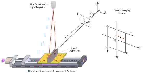
Figure 1.
System schematic.
As illustrated in Figure 1, consider a point P on the light stripe. By definition, P lies on both the object’s surface and the structured light plane. Let the equation of the structured light plane (emitted by the laser projector within the camera coordinate system) be
In Equation (1), coefficients a, b, c, and d define the structured light plane. Let denote the projection of point P onto the camera’s imaging plane. The line connecting P and intersects the optical center (the origin of the camera coordinate system), as shown in Figure 1. Here, is the principal point of the imaging plane, and aligns with the camera’s optical axis. Given the camera’s intrinsic parameters, the focal length f (distance from to the imaging plane ) is known, enabling the coordinates of in the camera frame to be expressed as (, , f). The line equation for is thus derived. Solving this line equation with the structured light plane equation yields the intersection point P, i.e., its coordinates in the camera frame. This process allows reconstruction of the entire light stripe projected onto the object’s surface. If the translation stage’s displacement relative to the prior image is known, and the current light stripe contour coordinates (solved via the plane equation) are , the true coordinates in the current frame are
By iteratively repeating this process, a dense 3D point cloud representing the scanned object is reconstructed within the camera coordinate system.
Based on the above analysis, the relationship between a point’s pixel coordinates on the object and its spatial coordinates in the camera frame is governed by the camera’s intrinsic parameters and the structured light plane equation within the camera coordinate system. Consequently, calibrating the camera and the structured light plane emitted by the projector is critical. Furthermore, reconstructing the complete point cloud requires calibration of the scanning displacement axis.
2.1. Calibration of Line-Structured Light-Based 3D Reconstruction Measurement System
Line-structured light-based 3D reconstruction technology analyzes the laser stripe projected onto an object’s surface, extracts the stripe’s centerline in pixel coordinates, and reconstructs the object’s 3D geometry using geometric transformations between pixel and spatial coordinates. Calibration aims to establish an accurate mathematical mapping between pixel coordinates and 3D spatial coordinates, which is a crucial step for ensuring accuracy and stability in 3D reconstruction. The accuracy of these calibrated parameters directly governs the system’s measurement precision. There are three types of parameter calibration: camera calibration [17], light plane calibration [18], and scanning-direction calibration [1,19,20]. Accurate scanning-direction calibration is critical to ensure geometric fidelity in 3D reconstruction; hence, scanning-direction calibration is a current research focus [2,21].
The independent estimation method [1] begins with camera calibration to determine the intrinsic parameters. A planar calibration target is then positioned stationary in space or mounted on the displacement platform. The system or target is translated along the scanning direction while the camera captures sequential images. The homography matrix H is estimated from these images, from which the camera’s extrinsic parameters are derived using the intrinsic parameters. The coordinates of corresponding control points in the camera coordinate system are subsequently computed using the extrinsic parameters. A linear equation is fitted to these points via the least squares method, with the line’s direction corresponding to the system’s scanning direction. This method necessitates decomposing the extrinsic parameters from the estimated homography matrix.
However, the independent estimation method is limited by inconsistent image clarity across positions, causing variable noise levels in extrinsic parameter estimations. This results in cumulative noise propagation during the 3D coordinate calculations of feature points, degrading the calibration accuracy. To address this, Liu [2] proposed a joint estimation method. Here, the displacement stage translates the target by fixed intervals, capturing images at each position. The method introduces constraints on the displacement distance, allowing all control points on the captured planar targets to be transformed into the coordinate system of the first captured planar target. By integrating the estimation of the scanning direction into the estimation of the homography matrix, a unified homography estimation can be performed using all the captured calibration images, thereby reducing errors.
By calibrating the scanning direction and utilizing the encoder on the displacement platform, the displacement between two consecutive object light stripe contours can be determined, enabling better reconstruction of the object’s surface point cloud.
The accuracy of scanning-direction calibration significantly impacts the shape of the object’s point cloud. If the scanning-direction calibration result is inaccurate, the relative positions of the cross-sectional point clouds will shift, leading to errors in the 3D reconstruction results and subsequent measurements. The joint estimation method [2] requires uniform displacement intervals for calibration images during data acquisition. Thus, its procedural complexity poses implementation challenges. We propose an improved scanning-direction calibration method that can achieve superior accuracy and does not require strict distance constraints, making it more user-friendly and easier to implement.
2.2. Extraction of Laser Stripe Center
Following system calibration, the mathematical relationship between the image pixel coordinates and the 3D spatial coordinates is established. However, reconstructing the point cloud contour still necessitates precise extraction of the laser stripe’s centerline. A critical factor influencing the accuracy of line-structured light measurement is the precise extraction of the laser stripe’s centerline projected onto the object’s surface [22]. The accuracy of this extraction process directly determines the performance of line-laser camera imaging.
Analysis of the grayscale intensity distribution of a laser-projected light stripe on an object’s surface (Figure 2) reveals a characteristic Gaussian profile. This property enables precise extraction of the stripe’s centerline.
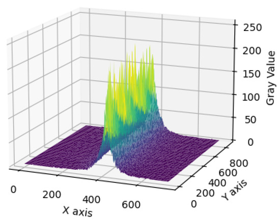
Figure 2.
Grayscale distribution of the light stripe.
Traditional methods for laser stripe centerline extraction encompass extremum-based, threshold-based, curve-fitting, and Hessian matrix-based approaches [23]. The Hessian matrix-based approach models the laser stripe as a curvilinear structure with a defined width. The algorithm first applies Gaussian filtering to suppress noise. The Hessian matrix is computed at each image point, where the dominant eigenvector corresponds to the normal direction of the stripe’s local curvature. Subpixel precision is achieved via Taylor expansion along this normal direction, solving for the position where the first derivative vanishes. This approach enables robust high-accuracy centerline detection even under varying illumination and noise conditions.
In recent years, researchers have optimized traditional methods or combined different approaches to propose new methods, improving the accuracy and speed of light stripe center extraction while enhancing the robustness. Examples include improved gray centroid methods [24] and modified Steger algorithms [25].
The accuracy of the light stripe centerline extraction is a crucial determinant of the measurement precision in line-structured light-based 3D reconstruction systems. The inherent variability in measured objects and complexity of extraction scenarios introduce diverse noise conditions, necessitating algorithms with robust generalization capabilities. While numerous traditional algorithms achieve high accuracy and speed in specific applications, their reliance on handcrafted features limits their adaptability to unpredictable noise and environmental variations. Consequently, artificial intelligence-based approaches, particularly deep learning, have gained prominence. Deep-learning models excel at learning complex noise patterns, offering superior generalization over traditional methods. Furthermore, deep-learning frameworks are well-established for semantic segmentation tasks, enabling precise pre-segmentation of light stripe regions to enhance centerline extraction [26].
3. Construction of the Line-Structured Light-Based 3D Reconstruction Measurement System
3.1. System Hardware Composition
As shown in Figure 3, the system hardware included a camera, a line-structured light laser, a displacement stage, and gauge blocks. Specifically,
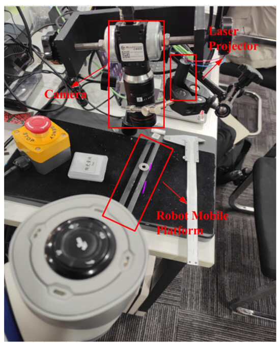
Figure 3.
System hardware composition.
- the camera model was MindVision MV-GE502GM, equipped with a lens of 35 mm focal length, featuring a resolution of 1280 × 1024 and a pixel size of 4.8 μm × 4.8 μm (Camera and its accessories are all sourced from Shenzhen MindVision Technology Co., Ltd., Shenzhen, China);
- the laser was a custom-made line-structured light laser;
- the robot mobile platform was essentially a one-dimensional linear displacement platform, with an error tolerance of ±0.02 mm;
- the gauge block was Grade 0, with a nominal size of 5 mm.
3.2. Calibration of the CCD Camera
The system employed Zhang’s calibration method [27], a planar calibration technique for camera calibration. The procedure involved capturing at least three images of a planar calibration target from varying camera poses. Assuming fixed feature points on the target plane, a world coordinate system was established with for all control points, enabling derivation of their pixel coordinates. Through the detection of feature point coordinates across multiple poses, the homography matrix linking 3D world coordinates to the 2D image plane was computed. Homography matrix constraints were then used to formulate a system of equations. Initially neglecting lens distortion, the linear system was solved via least squares optimization to estimate the initial intrinsic and extrinsic camera parameters. Subsequently, the lens distortion parameters were determined through maximum likelihood estimation. Finally, nonlinear optimization was used to refine all the parameters to minimize the reprojection errors and enhance the calibration accuracy.
Figure 4 illustrates a sequence of checkerboard (sourced from Shenzhen PointVision Technology Co., Ltd., Shenzhen, China) target images captured using Zhang’s calibration method. Upon extracting the pixel coordinates of the checkerboard grid corners, we computed the homography matrix, defining the world-to-image plane mapping. The camera’s intrinsic parameters as shown in matrix A are derived after calibration and presented in Equation (3). The optimized distortion coefficients are presented in Table 1, where represents 1st radial distortion; represents 2nd radial distortion; represents 1st tangential distortion; represents 2nd tangential distortion; and represents 3rd radial distortion.
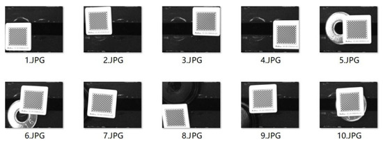
Figure 4.
Checkerboard target images captured using Zhang’s calibration method [27].

Table 1.
The numerical values of the distortion coefficients after calibration.
3.3. Calibration of the Light Plane
This system used a method based on cross-ratio invariance to calibrate the light plane equation in the camera coordinate system. Checkerboard images and corresponding laser images were captured as shown in Figure 5, which were jointly calibrated with the camera.
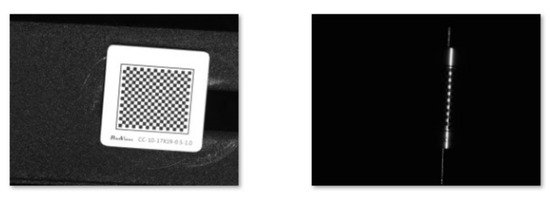
Figure 5.
Checkerboard images and corresponding laser images.
During camera calibration, the rotation and translation matrices for each checkerboard pose were derived. Since the relative positions of the laser images and checkerboard remained fixed, these matrices remained consistent across acquisitions. Leveraging cross-ratio invariance, the pixel coordinates of intersections between the light stripe and checkerboard grid were converted to world coordinates. These world coordinates were transformed into the camera coordinate system using the calibrated rotation and translation matrices. A least-squares optimization was then applied to fit the structured light plane equation. To achieve this, the light stripe centerline was extracted. Given the low noise and structural simplicity of the light stripe projected onto the calibration board, an undistorted image was first generated. The gray-level centroid method was employed for robust centerline extraction. The extracted points were smoothed, and a least-squares line fit was computed to determine the intersection points with the control lines. These results are illustrated in Figure 6.
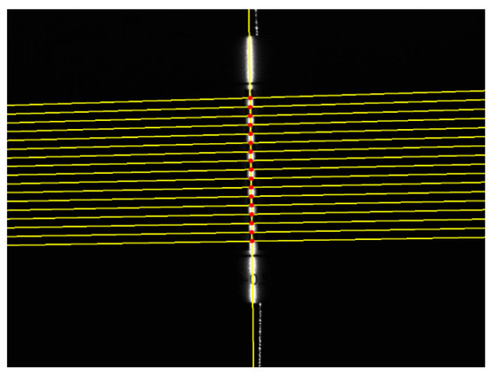
Figure 6.
Intersection points of the laser line and the checkerboard.
The equation of the light plane in the camera coordinate system was calculated as .
3.4. Extraction of the Light Stripe Center and Calibration of the Scanning Direction
This system employed a gray-level centroid-based algorithm for light stripe centerline extraction. This methodology balances computational efficiency, accuracy, and principled simplicity, making it well-suited for controlled environments with minimal noise interference. The workflow begins with image preprocessing using mean-filtering and Gaussian-filtering operations to suppress noise. The gray-level centroid algorithm is then applied to extract the light stripe centerline, which is subsequently smoothed to mitigate residual outliers. The experimental result of the extracted light stripe center is illustrated in Figure 7.
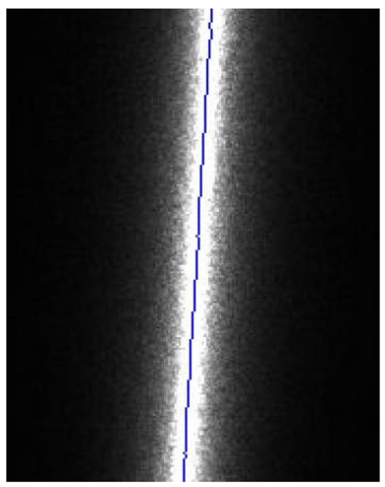
Figure 7.
Extracted light stripe center.
The calibration of the scanning direction employed the improved thinning method proposed in this study. Compared with traditional methods, this approach achieved higher accuracy and better stability, as described in Section 4.
3.5. System Software Composition and Scanned 3D Point Cloud
The system code was run on the Windows 10 operating system using the PyCharm 2024.1.3 (Community Edition) environment with Python 3.12. The code was divided into three modules: camera and light plane calibration, scanning-direction calibration, and camera image capture with light stripe center extraction. The modular structure diagram of the system code is shown in Figure 8.
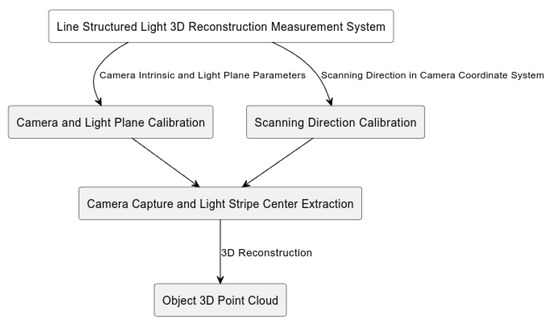
Figure 8.
Modular structure diagram of the system code.
Using the line-structured light-based 3D reconstruction measurement system constructed in this study and the improved thinning method proposed herein for scanning-direction calibration, the PCA board was scanned and reconstructed. The results are shown in Figure 9 and were used for subsequent defect detection, localization, and other operations.
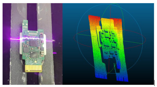
Figure 9.
PCA board point cloud.
Line-structured light-based 3D measurement can also be used for meter-level or larger objects. The methods used in previous studies were generally based on 3D point cloud registration [28,29].
4. An Improved Scanning-Direction Calibration Method
4.1. Problems with Traditional Methods
The independent estimation method proposed by Yi [1] derives extrinsic parameter matrices for individual calibration images. However, variations in image clarity introduce independent noise into each matrix. This noise cumulatively propagates during the transformation of the control points’ world coordinates () to camera coordinates (), thereby degrading the calibration accuracy. To empirically validate this limitation, a controlled experiment was conducted. A robotic translation stage displaced a planar target at fixed intervals while maintaining its pose relative to the camera. Seventeen images (including the initial position) were captured, and extrinsic parameters for each were estimated. The rotation matrix R was converted to a rotation vector via the Rodrigues formula (Figure 10). The results demonstrate variability in the estimated rotation matrices across images, attributable to inconsistent noise contamination.
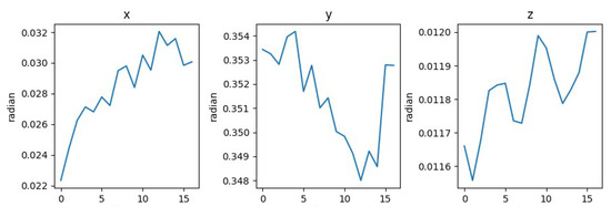
Figure 10.
Changes in x, y, and z radians.
The joint estimation method proposed by Liu [2] requires uniform displacement intervals for calibration images during data acquisition. While this method achieves superior accuracy compared to conventional approaches, its procedural complexity poses implementation challenges. Furthermore, reliance on low-precision displacement mechanisms introduces systematic errors due to inconsistent movement intervals, compromising the calibration accuracy.
4.2. Our Proposed Method
This study presents an enhanced refinement methodology building upon the independent estimation framework. The proposed technique employs iterative control point refinement via planar transformations while exploiting the rotational invariance under translational motion. By integrating multi-image data, the approach estimates an optimized rotation matrix and subsequently refines the translation vector through Levenberg–Marquardt (LM) [30] algorithm-based optimization to determine the scanning direction. The principal procedural stages are outlined below.
- 1.
- To mitigate noise arising from perspective distortion, variations in image clarity, and other factors, this study introduces an iterative control point refinement technique utilizing planar transformation [31] to enhance the spatial accuracy of control points.
Projection and lens distortions are primary contributors to reduced accuracy in feature point detection. For instance, circular calibration patterns subjected to perspective projection appear as ellipses when the imaging plane is non-parallel to the circle plane. This introduces an elliptical center deviation, where the projected circle center does not align with the ellipse’s geometric center. Similarly, checkerboard corner detection accuracy degrades under large perspective angles. To address this, planar transformation is applied to rectify perspective-distorted images into orthogonal views, enhancing control point detection precision. As demonstrated in Figure 11, this optimization reduces the reprojection error by .
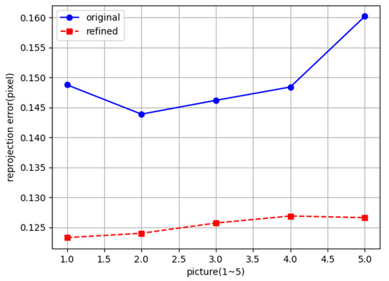
Figure 11.
Optimized control points.
- 2.
- Next, we combine all images and use the reprojection error as the evaluation criterion to select a more accurate rotation matrix.
The fixed relative pose between the camera and displacement platform during scanning implies that the rotation matrix derived from successive images should remain theoretically invariant. In practice, however, noise during image acquisition introduces variability in the estimated rotation matrices, a systemic limitation of independent estimation methods. The reprojection error, defined as the geometric discrepancy between the observed image coordinates of a 3D point and their reprojected counterparts using estimated camera parameters, serves as a critical accuracy metric. Minimizing this error enhances the control point detection precision and improves the reliability of the estimated projection and rotation matrices. Thus, reprojection error optimization enables the selection of robust rotation matrix estimates.
- 3.
- Using the rotation matrix estimated in step 2, the Levenberg–Marquardt (LM) algorithm is applied to estimate the translation vector.
The Levenberg–Marquardt (LM) algorithm is an iterative optimization technique designed for solving nonlinear least-squares problems. Serving as an enhancement of the Gauss–Newton method, it combines gradient descent and Gauss–Newton approaches to achieve robust convergence across diverse nonlinear optimization scenarios, including parameter estimation, curve fitting, and neural network training. In this study, its application to translation vector estimation yields superior performance compared to conventional methods.
The pseudocode for the method proposed in this study is shown in Algorithm 1.
| Algorithm 1: Our Proposed Method |
Require: Image list captured along motion direction ; camera intrinsic parameters A Ensure: Scanning direction vector V; rotation–translation matrix list Generate world homogeneous coordinates of control points based on ; ; perform image undistortion for each i in do (a) Compute corner coordinates of image i (b) Optimize corner coordinates using iterative refinement with planar transformation, save to (c) Estimate homography matrix H using and , computer reprojection error if then ; end if end for Extract rotation matrix R and translation vector T from using A Build reprojection error function f with input translation vector T and output is the error e between the reprojection point and the real control corner point; for each i in do (a) Use translation vector T as initial estimate; (b) Apply Levenberg–Marquardt algorithm to minimize reprojection error f, obtain ; save and rotation matrix R to ; end for Transform to camera coordinates using ; Group the points in such that points at corresponding positions on the checkerboard are grouped together into a , and merge every into ; for each i in do (a) Centralize points of direction i; (b) Obtain the direction vector of direction i through SVD and save into ; end for Return ; |
5. Results
To validate the proposed calibration method, images of a moving gauge block were captured as input, and the scanning directions were calibrated using three different approaches: the proposed scanning-direction calibration method, an independent estimation-based method, and a joint equidistant estimation-based method. Calibration was conducted for motion distances ranging from 1 mm to 5 mm, and the repeatability of each method was evaluated through statistical analysis. Furthermore, calibration accuracy was assessed by measuring a 5 mm gauge block after calibration, and point cloud plane fitting was employed to verify the algorithm’s effectiveness and measurement accuracy.
Figure 12 shows the calibration results of the scanning directions for motion distances of 1–5 mm using the proposed scanning-direction calibration method, the independent estimation-based calibration method, and the joint equidistant estimation-based calibration method. The standard deviations of the scanning directions estimated by the independent estimation method in the x, y, and z directions were 0.00712, 0.00152, and 0.0154, respectively. For the joint estimation method, they were 0.00516, 0.00166, and 0.0148, respectively. The standard deviations estimated by the method proposed in this study were 0.00152, 0.00164, and 0.00401, respectively. Comparing the results of the three calibration methods, the standard deviations in the y direction are nearly identical. However, the standard deviations in the x and z directions obtained by the proposed method are significantly smaller than those of the other two methods, indicating that the proposed method has better repeatability and stability, i.e., higher precision.
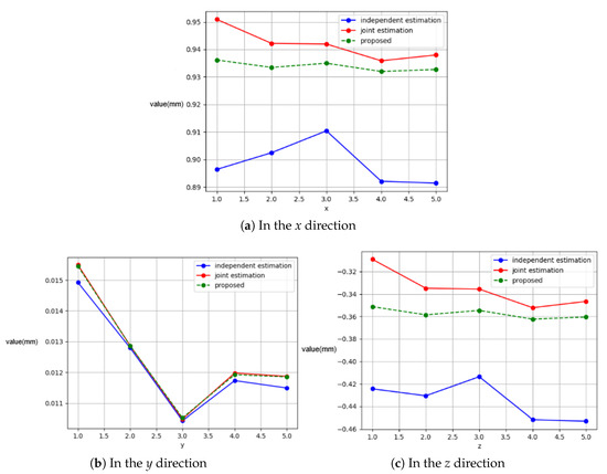
Figure 12.
Distribution of the scanning direction in the x, y, and z directions.
After calibrating the scanning direction of motion distances of 1 to 5 mm, the dimensions of a 5 mm gauge block were repeated measured by multiple reconstruction like the repeated experiments in [2]. As shown in Figure 13, the white strip-shaped point cloud above comes from the scanned upper surface of the gauge block, while the red and blue strip-shaped point clouds come from the scanned base. The white strip-shaped point cloud was fit into plane 1 (upper surface plane of the gauge block), and the red and blue strip-shaped point clouds were fit into plane 2 (upper surface plane of the base). Then, the distance between the two planes was calculated after each experiment. The final measurement results are presented in Table 2.
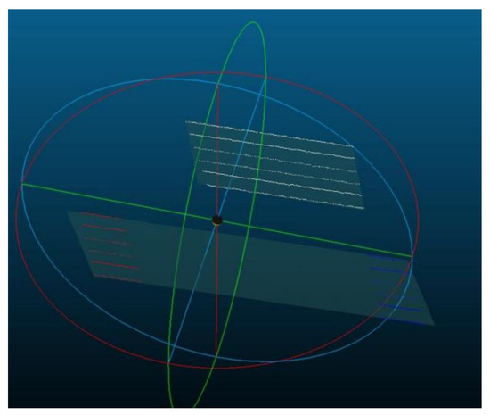
Figure 13.
Upper surface plane of the gauge block and the base.
Table 2.
Measurement results.
6. Discussion
From the table above, we see the following. The standard deviation of the gauge block dimensions measured using the scanning direction estimated by the independent estimation method is 0.0115, with a mean value of 4.9728 mm (the mean value of the error is 5 − 4.9728 = 0.0272 mm). The standard deviation of the gauge block dimensions measured using the scanning direction estimated by the joint estimation method is 0.00519, with a mean value of 4.9778 mm (the mean value of the error is 5 − 4.9778 = 0.0222 mm). The standard deviation of the gauge block dimensions measured using the scanning direction estimated by the proposed method is 0.00352, with a mean value of 4.98 mm (the mean value of the error is 5 − 4.98 = 0.02 mm). It can be concluded that the accuracy of the proposed method reduces the error by compared to the independent estimation method [1] and by compared to the joint estimation method [2], while also yielding more stable results.
7. Conclusions
In this study, we proposed an improved method to calibrate the scanning direction that iteratively optimizes control points via plane transformation while leveraging the rotational invariance of the rotation matrix during translation. By minimizing the reprojection error, an optimized rotation matrix is identified, and the Levenberg–Marquardt (LM) algorithm is subsequently employed to iteratively refine the displacement vector, enabling precise estimation of the scanning direction. Based on this, we developed a high-precision line-structured light-based 3D reconstruction measurement system. In the reconstruction measurement experiment of a 5 mm standard gauge block, our developed system achieved a mean value of the error of 0.02 mm with the standard deviation 0.00352.
Author Contributions
Formal analysis, S.P. (Shiyan Pang) and Y.H.; methodology, J.C. and S.P. (Shantao Ping); software, X.L.; validation, X.M.; writing—original draft, J.C. and S.P. (Shantao Ping); writing—review and editing, S.P. (Shiyan Pang) and Y.H.; S.P. (Shiyan Pang) and Y.H. have the same contributions, and they serve as the main contacts during peer review. All authors have read and agreed to the published version of the manuscript.
Funding
This research was funded by the National Natural Science Foundation of China (No. 62477018), the Joint Fund of the Ministry of Education for Equipment Pre-research (No. 8091B02072406), and the Fundamental Research Funds for the Central Universities (No. CCNU24JCPT005 and CCNU25ZZ104).
Data Availability Statement
The raw data supporting the conclusions of this article will be made available by the authors on request.
Acknowledgments
The authors would like to thank Shu Yuan for providing some experimental instruments.
Conflicts of Interest
The authors declare no conflicts of interest.
References
- Zeng, X.J.; Huo, J.W.Q. Calibrate method for scanning direction of 3D measurement system based on linear-structure light. Chin. J. Lasers 2012, 39, 108002. [Google Scholar] [CrossRef]
- Liu, C.W.; Duan, F.L.J. Calibration Method for Scanning Direction of Line-Structured-Light 3D Sensor. Chin. J. Lasers 2023, 50, 504001. [Google Scholar] [CrossRef]
- Sha, O. Research of 3D reconstruction and its key technologies based on binocular and linear structured light. Univ. Chin. Acad. Sci. 2023. [Google Scholar] [CrossRef]
- Lyu, Y.; Liu, Z.; Wang, J.; Jiang, Y.; Li, Y.; Li, X.; Kong, L.; Li, J.; Xu, M. A High-Precision Binocular 3D Reconstruction System Based on Depth-of-Field Extension and Feature Point Guidance. Measurement 2025, 248, 116895. [Google Scholar] [CrossRef]
- Cao, C.; Ren, X.; Fu, Y. MVSFormer: Multi-view stereo by learning robust image features and temperature-based depth. arXiv 2022, arXiv:2208.02541. [Google Scholar] [CrossRef]
- Zhao, L.; Liu, Y.; Men, C.; Men, Y. Double propagation stereo matching for urban 3-D reconstruction from satellite imagery. IEEE Trans. Geosci. Remote Sens. 2022, 60, 3058144. [Google Scholar] [CrossRef]
- Saovana, N.; Yabuki, N.; Fukuda, T. Automated point cloud classification using an image-based instance segmentation for structure from motion. Autom. Constr. 2021, 129, 103804. [Google Scholar] [CrossRef]
- Zhao, S.H. Research on Real-Time 3D Reconstruction System Based on Binocular Stereo Vision. Master’s Thesis, Xidian University, Xi’an, China, 2022. [Google Scholar] [CrossRef]
- Wang, F.; Galliani, S.; Vogel, C.; Speciale, P.; Pollefeys, M. PatchmatchNet: Learned multi-view patchmatch stereo. In Proceedings of the IEEE/CVF Conference on Computer Vision and Pattern Recognition (CVPR), Nashville, TN, USA, 20–25 June 2021. [Google Scholar] [CrossRef]
- Wang, Y.; Wang, X. On-Line three-dimensional coordinate measurement of dynamic binocular stereo vision based on rotating camera in large FOV. Opt. Express 2021, 29, 4986–5005. [Google Scholar] [CrossRef]
- Chen, Y.; Jiang, W.; Luo, Z.; Yang, L. A Novel 3D Reconstruction Method with a Binocular-Line Laser System. Measurement 2024, 227, 114238. [Google Scholar] [CrossRef]
- Ji, Y.; Zhong, J.; Li, Y.; Fu, J.; Liu, J. PCAPN: An Enhanced Feature Extraction Framework for Point Cloud. IEEE Access 2023, 11, 20786–20794. [Google Scholar] [CrossRef]
- Lu, Q.; Pan, Y.; Hu, L.; He, J. A method for reconstructing background from RGB-D SLAM in indoor dynamic environments. Sensors 2023, 23, 3529. [Google Scholar] [CrossRef]
- Liu, J.; Lu, C.; Wen, J.; Xiao, Y.; Yan, F.; Liu, Y. Three-dimensional measurement method based on binary coded fringes. Acta Opt. Sin. 2023, 43, 112004. [Google Scholar] [CrossRef]
- Nguyen, A.H.; Sun, B.; Li, C.Q.; Wang, Z. Different structured-light patterns in single-shot 2D-to-3D image conversion using deep learning. Appl. Opt. 2022, 61, 10105–10115. [Google Scholar] [CrossRef]
- Wang, F.; Wang, C.; Guan, Q. Single-shot fringe projection profilometry based on deep learning and computer graphics. Opt. Express 2021, 29, 8024–8040. [Google Scholar] [CrossRef]
- Huang, W.; Peng, X.; Li, L.; Li, X.Y. Review of camera calibration methods and their progress. Laser Optoelectron. Prog. 2023, 60, 1600001. [Google Scholar] [CrossRef]
- Xu, X.; Fei, Z.; Yang, J.; Tan, Z.; Luo, M. Line structured light calibration method and centerline extraction: A review. Results Phys. 2020, 19, 103637. [Google Scholar] [CrossRef]
- Pan, X.; Wu, J.; Li, Z.; Yang, J.; Zhang, C.; Deng, C.; Yi, Z.; Gao, Q.; Yu, M.; Zhang, Z.; et al. Self-Calibration for Linear Structured Light 3D Measurement System Based on Quantum Genetic Algorithm and Feature Matching. Optik 2021, 225, 165749. [Google Scholar] [CrossRef]
- Dai, G.; Zhang, Q.; Xu, X.; Zhao, B. A Calibration Method of Line-Structured Light System for Measuring Outer Circle Dimension during Machining. Results Eng. 2024, 23, 102525. [Google Scholar] [CrossRef]
- Li, T.; Liu, C.; Duan, F.; Fu, X.; Niu, G.; Liang, C.; Chen, A. A Light Plane Calibration Method of Line-Structured Light Sensors Based on Unified Extrinsic Parameters Estimation. Opt. Lasers Eng. 2025, 188, 108925. [Google Scholar] [CrossRef]
- Li, Y.Y.; Zhang, Z.Y.; Yuan, L. Survey on linear structured light stripe center extraction. Laser Optoelectron. Prog. 2013, 50, 100002. [Google Scholar] [CrossRef]
- Hu, K.; Zhou, F.; Zhang, G. Fast extrication method for sub-pixel center of structured light stripe. Chin. J. Sci. Instrum. 2006, 27, 1326–1329. [Google Scholar] [CrossRef]
- Zeng, C.; Wang, S.J.; Lu, H.; Kong, C. Center extraction algorithm of line structured light stripe. J. Image Graph. 2019, 24, 1772–1780. [Google Scholar] [CrossRef]
- Nan, F.; Li, D.; Gao, Q.; Xiao, Y. Implementation of adaptive light stripe center extraction of improved steger algorithm. Laser J. 2018, 39, 85–88. [Google Scholar] [CrossRef]
- Chen, X.Y.; Sun, X.; Sun, Y. Improved u2-Net for high-precision extraction of laser stripe centerline. J. Optoelectron. Laser 2025, 36, 61–68. [Google Scholar] [CrossRef]
- Zhang, Z. Flexible camera calibration by viewing a plane from unknown orientations. In Proceedings of the Seventh IEEE International Conference on Computer Vision, Kerkyra, Greece, 20–27 September 1999; Volume 1, pp. 666–673. [Google Scholar] [CrossRef]
- Chen, J.; Wu, X.; Wang, M.Y.; Li, X. 3D shape modeling using a self-developed hand-held 3D laser scanner and an efficient HT-ICP point cloud registration algorithm. Opt. Laser Technol. 2013, 45, 414–423. [Google Scholar] [CrossRef]
- He, Y.; Yang, J.; Hou, X.; Pang, S.; Chen, J. ICP registration with DCA descriptor for 3D point clouds. Opt. Express 2021, 29, 20423–20439. [Google Scholar] [CrossRef]
- Zhu, Q.; Li, S.; Xu, Z. Study of solving nonlinear least squares under large residual based on Levenberg-Marquardy algorithm. China Meas. Test 2016, 42, 12–16. [Google Scholar] [CrossRef]
- Datta, A.; Kim, J.S.; Kanade, T. Accurate camera calibration using iterative refinement of control points. In Proceedings of the 2009 IEEE 12th International Conference on Computer Vision Workshops, Kyoto, Japan, 27 September–4 October 2009; pp. 1201–1208. [Google Scholar] [CrossRef]
Disclaimer/Publisher’s Note: The statements, opinions and data contained in all publications are solely those of the individual author(s) and contributor(s) and not of MDPI and/or the editor(s). MDPI and/or the editor(s) disclaim responsibility for any injury to people or property resulting from any ideas, methods, instructions or products referred to in the content. |
© 2025 by the authors. Licensee MDPI, Basel, Switzerland. This article is an open access article distributed under the terms and conditions of the Creative Commons Attribution (CC BY) license (https://creativecommons.org/licenses/by/4.0/).