Article

Physically Based Thermal Infrared Snow/Ice Surface Emissivity for Fast Radiative Transfer Models

1
IMSG, Inc., NOAA/NESDIS Center for Satellite Applications and Research (STAR), College Park, MD 20740, USA
2
National Geospatial-Intelligence Agency (NGA), Springfield, VA 22150, USA
3
University Corporation for Atmospheric Research (UCAR), Boulder, CO 80301, USA
4
Joint Center for Satellite Data Assimilation (JCSDA), Boulder, CO 20740, USA
5
Cooperative Institute for Meteorological Satellite Studies (CIMSS), University of Wisconsin-Madison, Madison, WI 53706, USA
6
Space Science and Engineering Center, University of Wisconsin-Madison, Madison, WI 53706, USA
7
NOAA/NWS National Centers for Environmental Prediction (NCEP), College Park, MD 20740, USA
8
NOAA/NESDIS/STAR, College Park, MD 20740, USA
9
NOAA JPSS Program Office, Lanham, MD 20706, USA
*
Author to whom correspondence should be addressed.
Remote Sens. 2023, 15(23), 5509; https://doi.org/10.3390/rs15235509
Submission received: 8 September 2023 / Revised: 5 November 2023 / Accepted: 16 November 2023 / Published: 27 November 2023
(This article belongs to the Special Issue Advances in Thermal Infrared Remote Sensing II)

Abstract

:
Accurate thermal infrared (TIR) fast-forward models are critical for weather forecasting via numerical weather prediction (NWP) satellite radiance assimilation and operational environmental data record (EDR) retrieval algorithms. The thermodynamic and compositional data about the surface and lower troposphere are derived from semi-transparent TIR window bands (i.e., surface-sensitive channels) that can span into the far-infrared (FIR) region under dry polar conditions. To model the satellite observed radiance within these bands, an accurate a priori emissivity is necessary for the surface in question, usually provided in the form of a physical or empirical model. To address the needs of hyperspectral TIR satellite radiance assimilation, this paper discusses the research, development, and preliminary validation of a physically based snow/ice emissivity model designed for practical implementation within operational fast-forward models such as the U.S. National Oceanic and Atmospheric Administration (NOAA) Community Radiative Transfer Model (CRTM). To accommodate the range of snow grain sizes, a hybrid modeling approach is adopted, combining a layer scattering model based on the Mie theory (viz., the Wiscombe–Warren 1980 snow albedo model, its complete derivation provided in the Appendices) with a specular facet model. The Mie-scattering model is valid for the smallest snow grain sizes typical of fresh snow and frost, whereas the specular facet model is better suited for the larger sizes and welded snow surfaces typical of aged snow. Comparisons of the model against the previously published spectral emissivity measurements show reasonable agreement across zenith observing angles and snow grain sizes, and preliminary observing system experiments (OSEs) have revealed notable improvements in snow/ice surface window channel calculations versus hyperspectral TIR satellite observations within the NOAA NWP radiance assimilation system.

Graphical Abstract

1. Introduction

Accurate forward radiative transfer (RT) calculations are fundamental to satellite thermal infrared (TIR) radiance data assimilation for numerical weather prediction (NWP) models and within environmental data record (EDR) inversion (retrieval) algorithms [1,2]. Within operational contexts where minimal latency is essential, fast RT-models (RTM), or “fast-models” for short, are important for providing the timely, accurate forward calculations (calc) needed for global NWP assimilation and geophysical parameter retrievals [3]. Information about the lower troposphere and surface are derived from semi-transparent TIR spectral window channels (e.g., the 800–1200 cm 1  and 2400–3000 cm 1  spectral window bands), which require a priori information about both the surface emissivity and bidirectional reflectance distribution function (BRDF) within the forward radiance calculations performed by the RTM. Notable examples of fast-models include the U.S Joint Center for Satellite Data Assimilation (JCSDA) community radiative transfer model (CRTM) [2,4], used by the U.S. National Oceanic and Atmospheric Administration (NOAA) FV3GFS model, NASA/GMAO, and Naval Research Laboratory (NRL); the radiative transfer for TOVS (RTTOV) model [5], used by the European Centre for Medium-Range Weather Forecasts (ECMWF); NASA Langley Research Center (LaRC)’s principal component RTM (PCRTM) [6], used within their experimental all-sky (cloudy) retrieval algorithm; and University of Maryland Baltimore County (UMBC)’s stand-alone radiative transfer algorithm (SARTA) [7], used within the NOAA unique combined atmospheric processing system (NUCAPS) retrieval algorithm [8].
Today’s satellite passive TIR sounding systems used for assimilation and retrieval algorithms are based on high-resolution spectrometers, which provide atmospheric profile information within thousands of spectral channels (i.e., hyperspectral). Notable among those in low Earth orbit (LEO) are the Suomi National Polar-orbiting Partnership (SNPP) and joint polar satellite system (JPSS) cross-track infrared sounders (CrIS) [9], the Metop-series infrared atmospheric sounding interferometers (IASI) [10], and the NASA aqua atmospheric infrared sounder (AIRS) [11]. Both CrIS and IASI are Fourier transform spectrometers (FTS), whereas AIRS is a grating spectrometer. Information about the lower troposphere and surface is derived from these instruments within hundreds of microwindow channels, that is, narrow regions with relatively high transmittance located in between absorption lines. To forward-model accurately the observed radiance within these bands, the spectral emissivity of the surface must be specified with a similar degree of accuracy, given that the emissivity factors directly into the surface-leaving radiance.
Knowledge of the TIR surface emissivity over snow and ice surfaces is known to be important within the context of climate change, where the impact of greenhouse gas absorption has been observed to have a greater impact on the surface temperatures over polar regions, particularly the northern hemisphere (NH) Arctic [12]. The greater warming trend over polar regions is expected to continue for various reasons, one of which is feedback mechanisms. Recent studies have also brought attention to the importance of modeling snow/ice surface emissivity in the far IR (FIR) spectrum ( ν < 670 cm 1 ), given that it factors prominently within the total outgoing longwave radiation (OLR) budget [13], and extremely dry atmospheres characteristic of polar region conditions (sometimes with high surface elevations, e.g., Greenland, Antarctic, etc.) reduce FIR absorption to the point of becoming semi-transparent under these conditions [14].

1.1. Satellite Observing System Experiments over Snow-Covered Regions

The analysis and forecast errors in the polar regions are typically larger than other regions around the globe. The sources of these large errors include the lack of conventional in situ observations, errors in the inversion process, and lack of knowledge of the physics and dynamics of the cryosphere. Reducing the errors within the radiance data assimilation process will result in better use of the existing data, improve the analysis, improve our knowledge of weather over the cryosphere, and potentially increase forecast skill. It is noted that radiance assimilation is essentially a “retrieval” within a NWP model and is, thus, an ill-posed estimation problem with no unique solution. The importance of accurate surface/skin temperatures has long been recognized in this respect [15], and surface emissivity is key to this. While obtaining estimates of TIR-FIR surface emissivity for snow and ice is not trivial, these have the potential to be significantly more accurate than those for passive microwave (MW) channels.
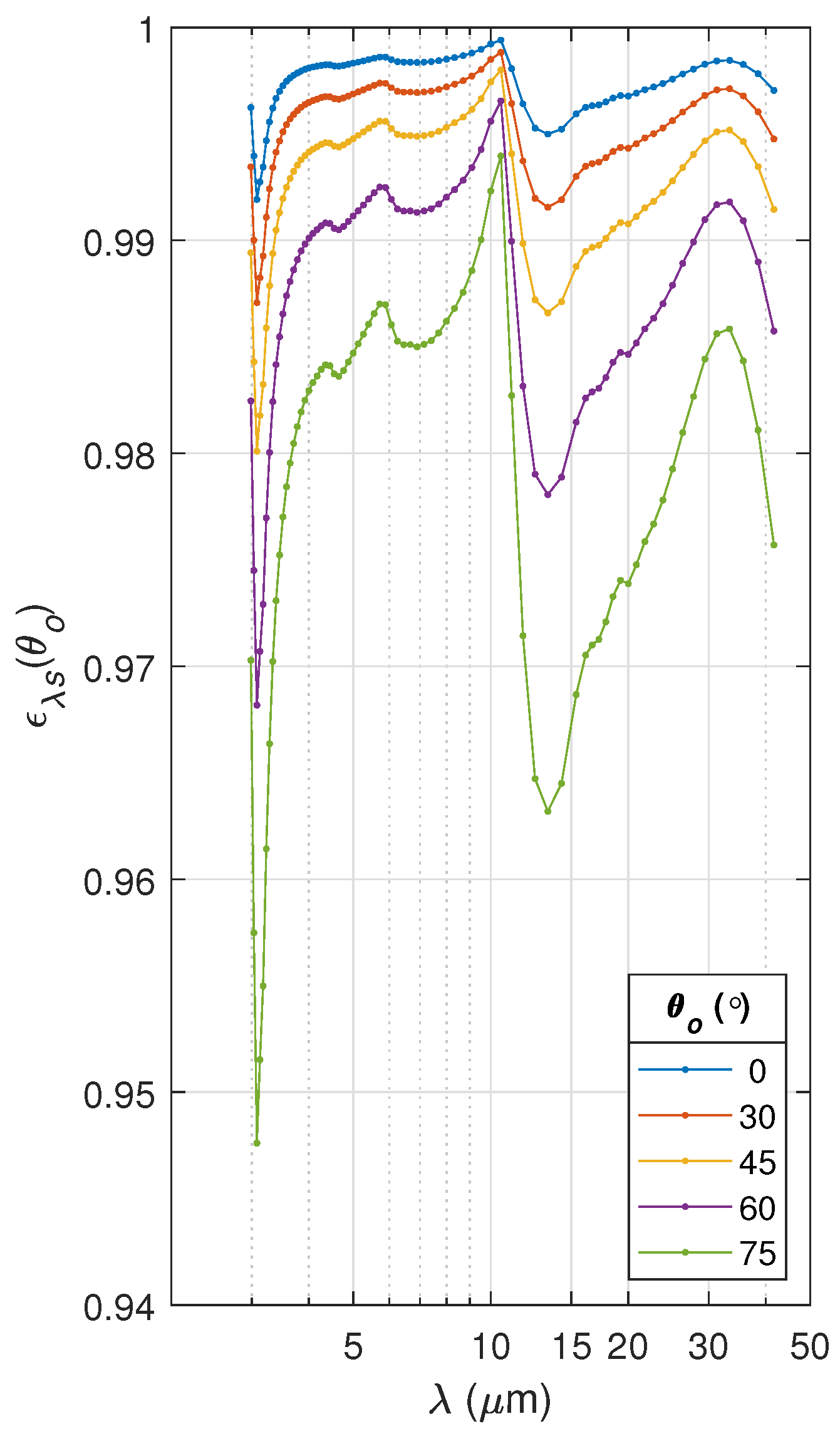
At NOAA/NCEP, the previous FV3GFS data assimilation studies [16] revealed discrepancies in clear-sky CRTM calculations (calc) versus CrIS/IASI observations (obs). Latitudinally varying discrepancies on the order of ≈0.5 K biases were observed over oceans, but much larger discrepancies (>5 K biases) have since been observed over snow/ice regions. The TIR emissivity a priori for snow/ice surfaces within the CRTM date back to the original CRTM Version 1 [4] and are shown in Figure 1. Notably, these spectra do not include observing angle dependence and are coarse spectral resolution. These are no longer adequate as constraints for retrieving lower tropospheric profile information from today’s operational hyperspectral TIR sounder instruments.
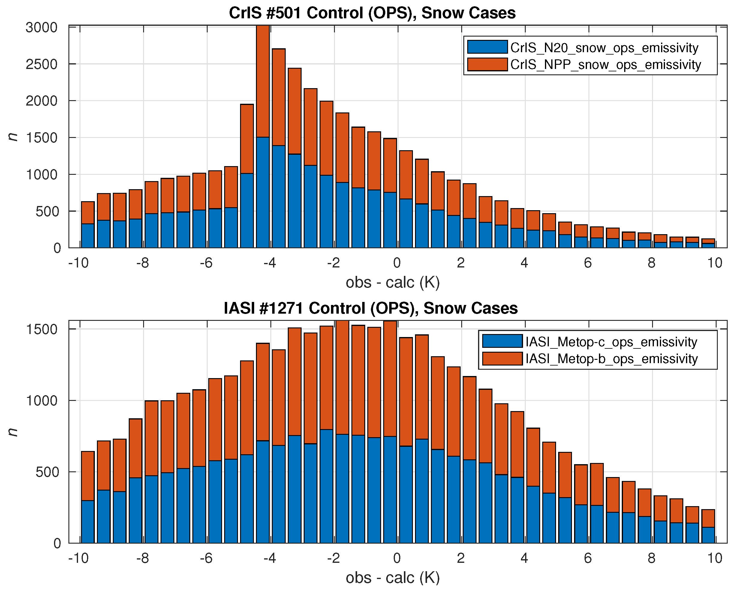
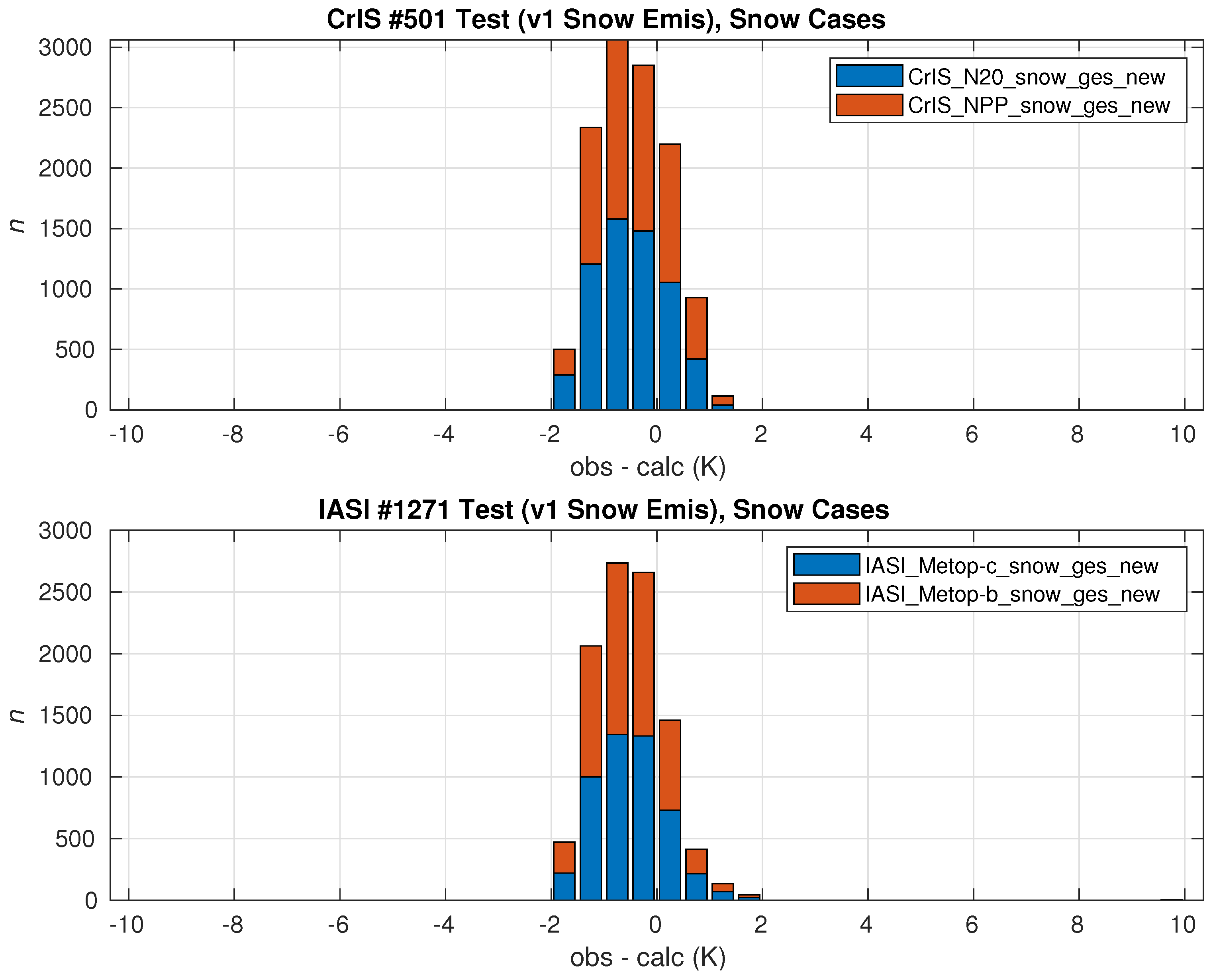
Figure 2 shows the results of an observing system experiment (OSE) of global “obs − calc” (sometimes also referred to as “obs minus background”, or “ O B ” for short, within data assimilation studies) for CrIS and IASI microwindow channels centered at 962.5 cm 1  (channels #501 and #1271, respectively) over snow surfaces within the FV3GFS gridpoint statistical interpolation (GSI) [17]. NOAA/NCEP uses the 962.5 cm 1  channel for obs − calc comparisons given that it is the cleanest longwave TIR microwindow channel. Other longwave microwindow channels can contain water vapor and/or other trace gas absorption lines (e.g., chlorofluorocarbons and nitric acid) that are not spectrally resolvable with the current data assimilation system. More discussion on the OSE is found in Section 3.1. The obs − calc spread over snow surfaces is more than a factor of 5 greater than the comparable results obtained over oceans, spanning ± 10 K. Both results are skewed negative, with the CrIS more visibly so, in addition to the noticeable kurtosis. The negative skewness suggests that there are likely issues with residual cloud contamination and, thus, not all of the ± 10 K is attributable to emissivity errors. However, by itself, cloud contamination would only contribute to negative obs − calc bias in transparent microwindows [18], so emissivity error is a contributor to the total error in the overall forward model calc. For reference, a systematic error of | 0.2–0.6| K was estimated for surface temperatures from a mere 1% uncertainty in emissivity over oceans [19].
Therefore, there is a need for improved snow/ice hyperspectral TIR-FIR surface emissivity model(s) for operational fast-models (viz., CRTM) as discussed more below. Discrepancies of this type are also evident within physical 1DVAR inversion (retrieval) algorithms; for example, operational temperature profile EDRs derived from NUCAPS. NUCAPS have heretofore used a regression algorithm based on cloud-cleared radiances [20] to provide a first-guess for emissivity over land/snow/ice surfaces (in addition to the T/H 2 O first guess), but more recently have implemented the combined ASTER MODIS emissivity over land (CAMEL) [21,22] as an option.

1.2. Surface Emissivity Considerations and Modeling Approaches

The directional emissivity of a terrestrial surface in thermodynamic equilibrium is defined as [23,24,25]
ϵ ν ( θ o ) I ν s ( θ o ) B ν ( T s ) ,
where θ o is the zenith observing angle, B ν is the Planck spectral blackbody radiance at surface skin temperature T s (K) and wavenumber ν (cm 1 ), and I ν s ( θ o ) ϵ ν ( θ o ) B ν ( T s ) is the surface-emitted radiance, typically in units of mWm 2 sr 1 cm. In practice, I ν s is separated from the surface-leaving radiance measured by an observer (e.g., a downlooking detector) at the surface, R ν s , by subtracting the surface-reflected radiance, which, assuming azimuthal symmetry, is given by
I ν s ( θ o ) = R ν s ( θ o ) 2 0 π / 2 r ν ( θ , θ o ) I ν ( θ ) cos ( θ ) sin ( θ ) d θ ,
where r ν ( θ , θ o ) is the bidirectional reflectance distribution function (BRDF) (sr 1 ) [26], and I ν is the downwelling atmospheric radiance at zenith angle θ . From Equations (1) and (2), one can see that what we call “emissivity” in practice involves the necessity of correctly specifying the surface reflectance, because it is convolved with the direct emission. In the case of a Lambertian (or perfectly diffuse) surface, the reflectance does not vary over the hemisphere ( θ = [ 0 , π ] ) ; that is, r ν ( θ , θ o ) = r ν ( π , θ o ) , and Equation (2) becomes
I ν s ( θ o ) = R ν s ( θ o ) α ν π , θ o F ν ,
where F ν 2 I ν ( θ ) cos θ sin θ d θ is the downwelling spectral irradiance (flux), and α ν ( π , θ o ) r ν ( π , θ o ) is defined as the hemispherical-directional reflectance or albedo (sr 1 ). Equations (1)–(3) provide the basis for both modeling and measuring spectral TIR surface emissivity, as discussed more in this paper.
There are generally two approaches taken for modeling the TIR emissivity of terrestrial surfaces, these being physical models and empirical models, with “hybrid” models involving a combination of the two. Physical models are based upon first-principles and simplifying assumptions for spectral regimes (e.g., the geometrical optics limit, etc.). Generally speaking, ocean surfaces are the simplest to model in the TIR-FIR spectral region, given that they are spatially uniform, with individual surface roughness elements, being large relative to the wavelength of radiation and their ensemble inclinations being known as a function of surface wind speed [27]. These unique features of ocean surfaces have allowed the development and use of physical models for over a decade [28]. Conversely, land surfaces are extremely inhomogeneous in terms of spatiotemporal uniformity, roughness, and optical properties, and thus, over land, empirically-derived merged atlases, for example CAMEL [21,22] have been implemented, and these include snow and ice surfaces. CAMEL ice and snow emissivity are based on principal component (PC)-based regression between the combined MODIS and ASTER emissivity retrievals and four laboratory measurements from the Ecosystem Spaceborne Thermal Radiometer Experiment on Space Station (ECOSTRESS) spectral library, (formerly known as the Advanced Spaceborne Thermal Emission Reflection Radiometer, ASTER spectral library) [29].
However, as with oceans, the RT associated with snow and ice surfaces in principle may be modeled physically assuming idealized conditions (e.g., uniform, level, pure snow/ice surfaces). Notable examples of these have included models developed by Berger [30], which exclusively relied on geometrical optics; Wiscombe and Warren [31], which was based on Mie-scattering and delta-Eddington approximation; and Wald [32], which was based on a “diffraction-substraction” method to account for the close packing of snow particles. This paper outlines the work undertaken toward selecting, deriving, implementing, and testing a hybrid physical model for calculating a priori snow/ice surface emissivity for convenient implementation within CRTM and other fast-models, as well as global empirical atlases such as CAMEL.

2. Methodology

After conducting a thorough literature review of the previous research on the topic [33,34], we chose to implement the Wiscombe and Warren (1980) [31] snow albedo model (hereafter, “WW80”) in the initial step toward a CRTM forward model upgrade. We found the WW80 model to be ideal in terms of both theoretical basis (applying the Mie-scattering theory for single scattering by randomly oriented snow particles [24] modeled as spheres, discussed more below) and practical application (encapsulated within a relatively simple formula providing albedo as a function of observing angle). Early follow-up studies indicated some success in applying the WW80 model to TIR emissivity [35], and it also currently forms the basis for solar spectrum reflectances in the snow, ice, and aerosol radiative model with adding–doubling, Version 3 (SNICAR-ADv3) community model [36].
In terms of its TIR application, Warren [33] acknowledged that the WW80 model “assumes that the scattering properties of a snow grain are not affected by the proximity of neighboring grains” (i.e., it assumes the far-field limit in the application of the Mie-scattering theory [31]), which is legitimate for solar wavelengths. Dozier and Warren investigated various physical dependencies (e.g., snow density, non-sphericity), and they concluded under the subsection “Density” that “near-field effects are unlikely to be important for λ < 50 μ m”. They based this on calculations simulating near-field effects by making an adjustment to the real part of the refractive index, n ν , but their model was otherwise based on WW80, as is encapsulated in their Figure 1b. Wald [32] pointed out that the far-field assumption is valid only for particles “separated by three particle radii” ( 3 r ), which breaks down for larger sizes when snow grains become opaque, densely packed, and welded together. To model emissivity for a particle radii r > 50   μ m, Wald proposed a “diffraction subtraction” methodology but acknowledged that WW80 is otherwise legitimate for small particle sizes r < 20   μ m in the TIR [32]; unfortunately, a straightforward expression or derivation for emissivity was not provided in the paper.

2.1. Wiscombe–Warren (WW80) Model

In solar spectrum convention (e.g., the WW80 model), the spectral surface albedo is typically defined as directional-hemispherical ( θ o , π ) reflectance, given by [26,35,37,38,39,40]
α ν ( θ o , π ) F ν F ν ( Δ θ o ) = F ν μ o π I ν ( θ o ) ,
where ν is the spectral wavenumber (cm 1 ); θ o is the local zenith angle of the origin (or, reciprocally, the observer); μ o cos θ o , F ν and F ν ( Δ θ o ) are the hemispherical upwelling (surface-leaving) and conical downwelling (surface-incident) fluxes, respectively; and I ν ( θ o ) is the radiant intensity defined by F ν / π  [41]. Note that lower-case letter o subscripts have been chosen to signify either the “origin” or “observer” angle to distinguish it from naught (0) subscripts, which are reserved in this paper to designate zeroth order polynomial expansions or zeroth moments. As written, the denominator term, μ o π I ν , is the surface-incident conical flux, which is typically taken to be the solar irradiance (a source term) in visible-spectrum applications (usually denoted π F ). However, in the current application (TIR-FIR emission), by reciprocity, the albedo given by Equation (4) is also equivalent to the hemispherical-directional ( π , θ o ) reflectance [35,42] referred to in Equation (3); that is, α ν = α ν ( π , θ o ) , and thus, θ o may instead be interpreted as the observer angle.
From Equations (1), (3), and Kirchhoff’s law, the hemispherical-directional snow/ice emissivity may then be obtained from [24,31,35]:
ϵ ν s ( θ o ) = 1 α ν ( π , θ o ) .
To derive the albedo (and thus, emissivity) analytically, expressions must, thus, be found for F ν and F ν , the derivations of which are detailed in Appendix A, Appendix B, Appendix C and Appendix D.
The Mie theory provides fundamental values for the Mie efficiencies pertaining to single-particle extinction ( Q e ), scattering ( Q s ), absorption ( Q a ), and backscattering ( Q b ), from which other parameters such as the single-scattering albedo ( ϖ ) and asymmetry parameter (g) can be derived as a function of the complex refractive index, N ν  [43,44], and snow grain size (particle radius), r. In reality, snow grains are not spherical, and for any given snowpack, there are a range of particle sizes. Typically, these complications are accounted for by introducing a “radiatively effective radius” for a size distribution of spheres defined as r e 3 β / ρ i , where β is the specific surface area, and ρ i is the density of ice [45]. Because this paper assumes Mie scattering, the terms “particle size”, “particle radius”, and “snow grain size” are used interchangeably to refer to a mean effective particle size of a given snowpack.
The authors adapted and utilized MATLAB research-code for performing Mie calculations (after Ref. [46]); MATLAB is extremely well-suited for this purpose, possessing built-in Bessel functions while efficiently using matrix syntax that optimally retains direct correspondence with the theoretical formulations. However, given that the single-scattering of individual snow grains tends to have a strong forward peak, the WW80 model applies the delta-Eddington approximation (D–E) for radiative transfer, discussed more in Appendix B, to account for multiple scattering within the RT equation (RTE). The D-E approximation begins with a truncated two-term Henyey–Greenstein (H-G) phase function but accounts for the strong forward scattering peak of snow by including a Dirac delta function term. The D-E phase function is, thus, approximated as
P ν * ( cos Θ ) 2 f ν δ ( 1 cos Θ ) + ( 1 f ν ) ( 1 + 3 g ν * cos Θ ) ,
where asterisks denote D-E approximation quantities, f ν is the forward scattered fraction, and g ν * g ν 1 + g ν is the asymmetry parameter of the truncated Eddington phase function. The original Eddington approximation is then applied to the D-E scaled RTE (using the simplified phase function), thus, allowing the RTE to be significantly simplified into an analytically solvable set of coupled ordinary differential equations (ODEs) (cf. Appendix B.2 and Appendix B.3).
From these assumptions and after considerable derivation (see Appendix A, Appendix B, Appendix C and Appendix D), solving for the upward and downward fluxes, F ν and F ν , it can be shown that the albedo (i.e., the hemispherical-directional BRDF) for a flat, uniform snowpack surface, assuming quasi-infinite optical depth ( τ ν ), is given by [31]
α ν ( θ o ) = ϖ ν * · 1 1 + φ ν 1 b ν ξ ν cos θ o 1 + ξ ν cos θ o ,
where ξ ν , b ν , and φ ν , denote intermediate variables, defined as
ξ ν 3 ( 1 ϖ ν * g ν * ) ( 1 ϖ ν * ) ,
b ν g ν * 1 ϖ ν * g ν * ,
φ ν 2 ξ ν 3 ( 1 ϖ ν * g ν * ) ,
ϖ ν * ( 1 f ) ϖ ν 1 f ϖ ν being the D-E scaled Mie single-scattering albedo.
Note that in previous publications [31,47,48,49], the intermediate variable represented by φ ν in Equation (A66) was denoted with an upper case P. In the original WW80 paper, no explanation was given as to what the significance was behind that specific symbol, which led to unnecessary confusion, especially given that P is also the standard symbol for the phase function, P ν , not to mention the Legendre polynomials used in the derivation (cf. Appendix A), these being directly relevant to the physical model. It was subsequently learned during the course of this research that P was a purely mathematical construct that originated during the solution of the ODEs (cf. Appendix C) but otherwise carries no physically relevant meaning within the symbol itself for albedo. Given that TIR-FIR albedo and emissivity are physical variables, we have, thus, chosen to break from this usage, rendering it instead using an analogous Greek letter φ ν to avoid further confusion with the variables mentioned.
Although the assumption of quasi-infinite optical depth is justified in the longwave TIR-FIR spectrum, we nevertheless implemented the full-scattering version of the WW80 model [Equation (3), op. cit.; cf. Appendix D], where the range of validity extends to solar-reflectance (visible) wavelengths. Implicit in the Mie-scattering calculations are functional dependencies on snow grain size (effective radii), r ( μ m), and complex refractive index, N ν . For both the Mie calculations and the Fresnel reflectance calculations discussed in Section 2.2 below, we use the temperature-dependent, TIR-FIR optical constants of ice ( N ν ) published by Iwabuchi and Yang [44]. It should be noted that snow grain size is known to grow as a snow pack ages [50], and thus, this parameter accounts for the age of the snow pack. Thus, the snow surface emissivity computed from Equation (5) is a function of θ o , r, and N ν ( T ) .
As a “sanity-check”, the output from our research code implementation of the WW80 model was tested against those published previously by Dozier and Warren [35] to confirm that the model was implemented properly. Figure 3 shows results from our implementation of Equations (5) and (7) in a manner that visually duplicates the results published by Ref. [35]. The subtle differences between our implementation and Ref. [35] may be attributed to the difference in the optical constants used in the Mie calculations; in our case, we used the most recent temperature-dependent data available [44], which are expected to be more accurate than those that were available to Ref. [35] in 1982.
The model calculations were then tested against the earlier published laboratory and field measurements, namely, the ECOSTRESS (ASTER) library [29,51] and those of Ref. [52], the latter including multi-angle field observations. The model calculations were found to agree reasonably well for smaller particle sizes ( r < 30   μ m) but did not capture the size dependence for larger sizes. It was subsequently learned that this is a known problem with the WW80 model, but the model was nevertheless implemented within an offline version of the CRTM, given that the particle size dependence was a lesser concern compared to the spectral and angular dependencies. Results from the initial CRTM implementation of the WW80 model are presented in Section 3.1.

2.2. Hybrid Physical Model

The additional research into the large particle size problem led to the observation that the albedo of snow surfaces gradually becomes more specular as it becomes coarser grained. We directly noticed this ourselves when studying the field and laboratory data, but we subsequently learned that others had also noticed this previously [32,53]. As snow ages, the snow grains not only grow larger via sublimation metamorphosis [50] but they also “weld” together [32] into an ice surface as opposed to a scattering layer. Because of the relationship between snow grain size and snowpack age, the particle radius parameter is necessary to account for the age of the snow pack. Table 1 reproduces the snow grain size measurements (mean length, diameter, and constriction width, in micrometers) observed by Yosida [50] as a function of age, which provide here an indication of the relationship between the snowpack grain size and age.
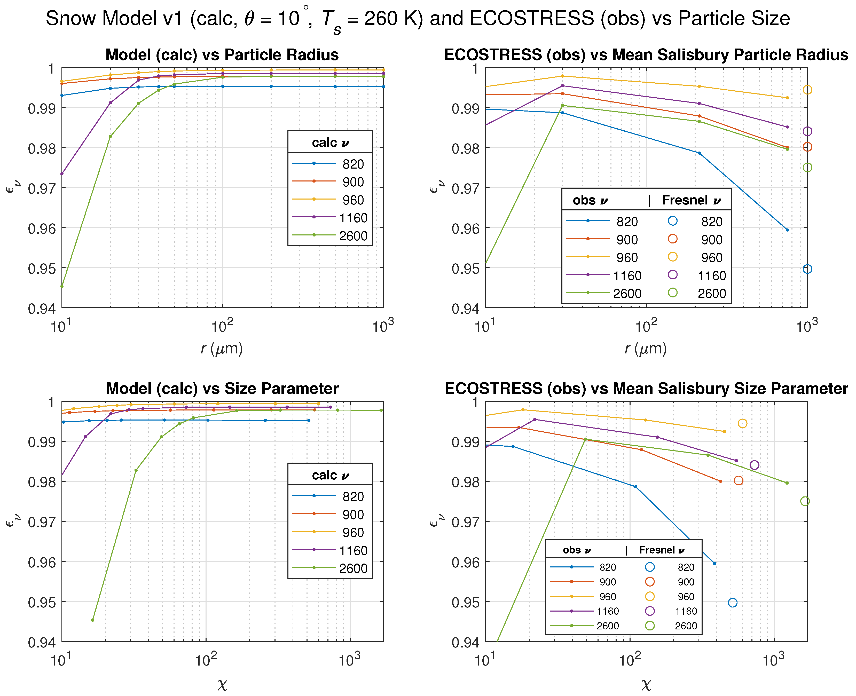
A subsequent examination of the particle size dependence seemed to reveal a linear transition from the scattering-layer regime (i.e., the WW80 model) to a Fresnel surface reflectance regime, as illustrated in Figure 4. In this figure, dependencies on particle size are shown as a function of particle radius (r) and size parameter ( χ 2 π r / λ ) in the top and bottom row plots, respectively. The left and right columns show the WW80 model calculations and ECOSTRESS measurements [29,51], respectively. Here, it can be seen in the left hand plots that the WW80 model asymptotes to constant values of emissivity above a certain particle size, these varying with the spectral channel, with the higher wavenumber (shorter wavelength) channels (e.g., 1160 and 2600 cm 1 ), being the last to flatten out as would be expected. In the right hand plots, however, the laboratory measurements show a decrease in emissivity where the WW80 flattened out. It was then noticed that, roughly speaking, these emissivities could be linearly extrapolated to the Fresnel values at a nominal large particle size (i.e., 1000 μ m). These results (as well as Refs. [31,32]) suggested that an “effective emissivity” for snow/ice surfaces could be expressed conceptually as a linear combination of diffuse layer-scattering and quasi-specular surface fractions; that is,
ϵ ν * = η s ϵ ν s + ( 1 η s ) ϵ ν ρ ,
where ϵ ν s and ϵ ν ρ are the emissivities for the snow and Fresnel reflecting ice-surface areas, respectively; η s is the fractional surface area that behaves as a multi-scattering snow layer (as in the WW80 model); and 1 η s is the quasi-specular area arising from a surface made up of a quasi-random ensemble of ice crystal facet planes, oriented at an effective (average) oblique angle relative to the observer. For η s 1 , the snowpack surface reflects and emits as a scattering layer (as in the WW80 model), whereas η s 0 implies a fused Fresnel ice surface.
In this vein, Hori et al. [53] proposed a “semi-empirical” model (hereafter, “H13”) that expresses the snow surface emissivity as a linear combination of an isotropic blackbody component, where ϵ ν s 1 and η s 1 η ρ in Equation (11), along with a quasi-specular (ice facet) component, η ρ , within the overall “bulk” surface, given by
ϵ ν ρ ( θ , r , N ν ) η ρ ( r ) 1 ρ ν ( θ , N ν ) + 1 η ρ ( r ) 1 ρ ν θ ¯ , N ν ,
where θ ¯ 45 , and ρ ν is the unpolarized Fresnel reflectance coefficient, taken to be the average of the polarized reflectances for intensities (i.e., the square of the absolute value of the amplitude coefficients). Using the field measurements from their earlier paper [52], Hori et al. [53] empirically determined the specular fractions for various snow samples, the results of which are summarized in Table 2.
Hori et al. [53] referred to their model as “semi-empirical” given that it relied on their earlier field measurements to derive their specular fractions. However, it should be noted that Equation (12) has a physical basis as an approximation for quasi-specular reflectance, which is characterized as having a finite reflection lobe with a significant peak centering around the specular angle [54]. Generally speaking, quasi-specular reflectance arises from large-scale surface roughness caused by surface elements with large size parameters (i.e., dimensions or curvature that are large relative to the wavelength of radiation, r λ ), although it has also been shown to arise from lattices of Mie-scattering spheres (size parameters χ = 2 , r λ ) [55]. In the case of an idealized snowpack, the specular component can arise from randomly oriented snow facets with an ensemble effective orientation, θ ¯ , which may be approximated as the mean slope of the facets. Assuming spherical particles (as in the WW80 Mie-scattering model) and disregarding shadowing effects, the mean inclination happens to be θ ¯ 45 . Thus, while it may be “semi-empirical”, it should nevertheless be kept in mind that this is a physically reasonable approach in lieu of having an observed statistical description of snow/ice facet slopes, as is (fortuitously) the case in ocean emissivity models [28,56].
The H13 semi-empirical model is found to compare favorably for larger particle sizes, but unfortunately, this is not true for the small particle sizes ( r < 50   μ m) included in the ECOSTRESS data. However, it is precisely these smaller particle sizes where the WW80 albedo model shows good agreement. Because the WW80 and H13 models appear to capture the observed small and large particle size regimes, respectively (with a transitional region around 30–100 μ m), we adopted a modified “effective emissivity” approach based on Equations (5), (11) and (12). Rather than assuming a blackbody for ϵ ν s in Equation (12), we instead assume that layer scattering dominates under these conditions [32], and thus, from Equations (5) and (11), we obtain
ϵ ν * ( θ o , r , N ν ) = η s ( r ) 1 α ν ( θ o , r , N ν ) + 1 η s ( r ) ϵ ν ρ ( θ o , r , N ν ) ,
where α ν is the albedo predicted by the WW80 model given by Equation (7).
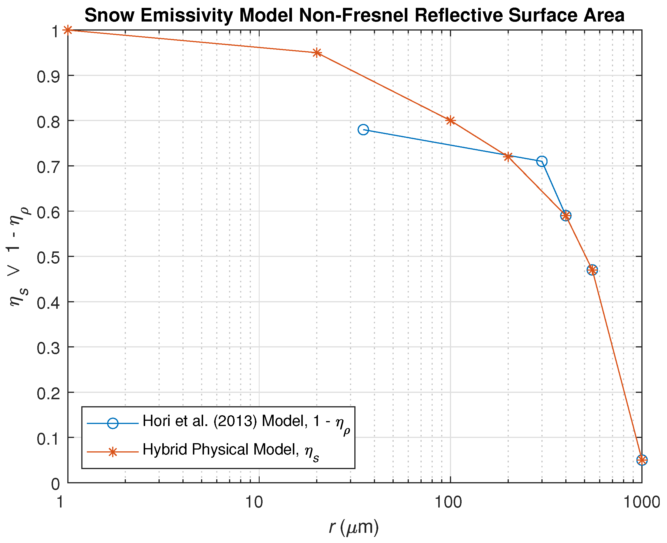
For larger particle sizes ( r 400   μ m), we use the “specular fractions”, η ρ 1 η s , proposed by Ref. [53], but for smaller particle sizes, we extrapolated these in log-r space to unity at r = 1   μ m as a transition to the layer scattering regime (WW80 model) for these sizes, as illustrated in Figure 5. The physical interpretation of this hybrid physical model approach may be seen as a linear transition from a multiple scattering layer regime (modeled by small, Mie-scattering spherical snow grains), to a quasi-specular surface-reflectance regime consisting of large, fused ice crystals acting as randomly oriented facets (as in ocean reflectance models, e.g., [57]) with an effective (approximately average) inclination angle of 45 .

3. Results and Discussion

Both the hybrid physical model (v1.1), Equation (13), and the WW80 model (quasi-infinite optical depth limit), Equation (7), are simplified as 4-D lookup-tables (LUT) with dimensions ν , θ o , r, and T; that is, ϵ * ( ν , θ o , r , T ) (see Table 3 for LUT parameter ranges), for convenient application within fast-forward models (e.g., CRTM, RTTOV, PCRTM, SARTA, etc.), as well as within spectral libraries and atlases (e.g,. CAMEL). The results that follow are based upon these model output LUTs.

3.1. Preliminary OSE Using WW80 Model

Concurrent with researching the problem of larger particle sizes, a preliminary OSE was performed to test the impact of the initial CRTM snow emissivity model upgrade on global obs − calc based solely on the WW80 model (i.e., CRTM physical snow emissivity model v1). As with the control experiment briefly highlighted in Section 1 (cf. Figure 2), the OSE used the lowest resolution FV3GFS_V16 over the time period of 28 July to 30 September 2021, with obs obtained from the SNPP/NOAA-20 CrIS and the Metop-B/C IASI for a longwave TIR microwindow, ν 962.5 cm 1 ). All the satellite bias corrections were reset and a 5-week spin-up was conducted. The baseline (control) OSE was based on the existing CRTM v2.3.0 snow/ice emissivity a priori [4]. The test run was conducted using a stripped-down LUT from the v1 (WW80) snow/ice emissivity physical model that was hard-coded into the GSI for two zenith observing angles ( θ o = 10 , 60 ) and a nominal particle size of r = 200   μ m. The LUT-interpolated coarse-resolution model emissivity spectra were then adjusted based on a linear fit to the surface channel data.
Figure 6 shows the histograms from the test OSE presented in the same manner as Figure 2. A significant improvement can be seen in terms of both the spread and bias, with the standard deviations now closer to the 1 K range, which is more than a factor of 5 reduction. Note that these results have only used a subset of the initial snow emissivity model LUT (v1) based only on WW80, which is known to break down at larger particle sizes. It is, thus, believed that the improvement in global obs − calc is due primarily to the improved angular and spectral dependence afforded by the physical model (at least for this particular spectral channel) over the original CRTM snow/ice emissivity a priori [4]. Although significantly reduced, there remains a negative bias in these results, which may be the result of residual cloud/aerosol contamination [18] or some other interference not accounted for in the clear-sky RT, as well as the deficiency in modeling snowpacks with larger snow grain sizes, as is the case with aged snowpacks. Other factors not accounted for in the global OSE sample include non-homogeneous snow/ice surfaces (e.g., non-snow/ice surfaces within the sensor field-of-view); non-random, macroscale topographical features that change the mean inclination angle of the surface (e.g., sastrugi) [58]; non-spherical snow grain shapes [45]; and snowpack impurities such as aerosols [59]. Although the dependence of the complex refractive index N ν on surface temperature, T [44], is included in our implementation of the three emissivity models (H13, WW80, and hybrid physical), this was not taken into consideration within the OSE. However, these are all most likely second order effects after the particle size and cloud contamination factors.

3.2. Comparison of Models against Published Laboratory and Field Measurements

We tested the output from the three snow emissivity models discussed in this paper (H13, WW80, and our hybrid physical model, Equation (13)) against published laboratory and field data. The results are summarized in multi-panel figures below.
Figure 7 shows a comparison of the snow emissivity model calculations (H13, WW80, hybrid physical model in the first three columns, respectively) against emissivity derived from laboratory measurements of snow albedo [51] from the ECOSTRESS library [29], shown in the rightmost column. These measurements were taken at a single near-nadir incidence angle ( θ o = 10 ), but they span fine, medium, and coarse snow grain sizes ( r 30 μ m, 212.5 μ m, and 750 μ m; flat ice (effective r 1000   μ m); and frost ( r 3.25   μ m). It can be seen that the H13 and WW80 models perform well for large and small particle sizes, respectively (left two columns, respectively), but break down in the opposite regimes. The hybrid physical model (third column from the left) captures both large and small particle size regimes as designed, including the prominent low-emissivity spectral features in the smaller particle size regime ( r 100   μ m), known as reststrahlen bands (bottom plot), and the overall increase in spectral emissivity with particle size in this regime, as well the subsequent spectral “flattening” and decrease in emissivity (top plot) in the larger particle size regime ( r > 100   μ m).
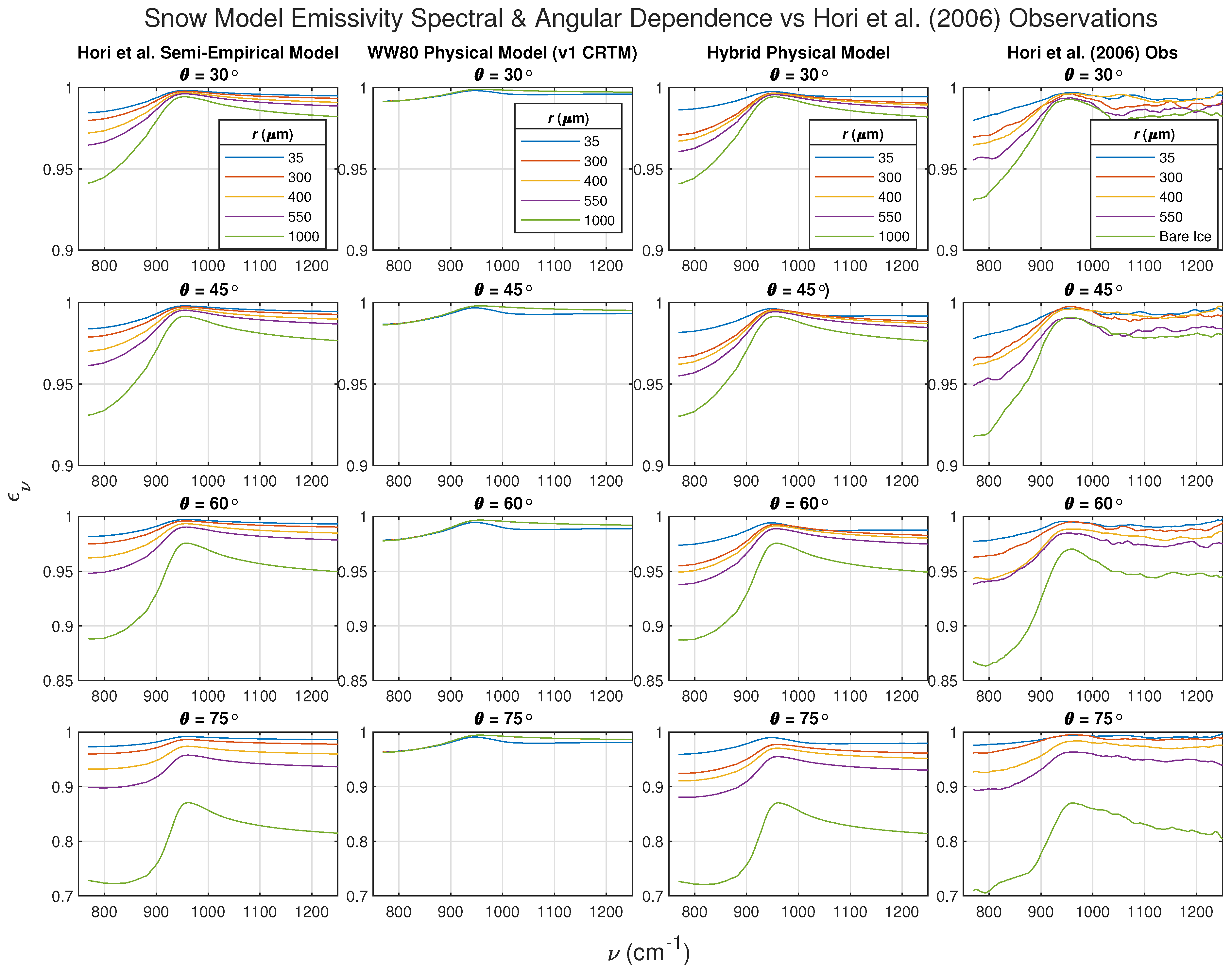
As mentioned previously, the observer angle dependence ( θ o ) in surface TIR-FIR emissivity is usually a first-order dependency for terrestrial surfaces, with emissivity generally decreasing with the observer angle as a result of increasing reflectance. To test the three models’ performance for θ o > 10 , we compared them against the Hori et al. [53] field measurements of snow cover emissivity (provided to us courtesy of M. Hori, University of Toyama), which span the θ o range of 0–75  and median particle sizes r 35   μ m (i.e., where quasi-specular reflectance begins to dominate over layer multiple scattering effects); the results are summarized in Figure 8 and Figure 9, with the columns again arranged from left to right for the H13 model, WW80 model, hybrid physical model, and field measurements, respectively.
In Figure 8, the emissivities are plotted as a linear function of particle radii, r, for a selection of monochromatic longwave TIR channels, with the rows arranged top to bottom showing results for θ o = 30 , 45 , 60 , 75 , respectively. These plots clearly show the general decrease in emissivity with θ o (top to bottom plots) for all the particle sizes considered r 35   μ m, as well as the decrease in emissivity with r for these sizes. Here it is also evident that the WW80 model does not adequately capture the particle size dependence, remaining almost constant but otherwise reasonably capturing the angular dependency for the smallest particle sizes considered ( r 35   μ m). The H13 model (left column) shows the best overall agreement with the measurements (right column), but this is expected given that the H13 model was empirically tuned to agree with those measurements. The hybrid physical model yields very similar results to the H13 model, albeit exhibiting a somewhat greater decrease in emissivity with particle size at the largest observer angles, θ o = 75 .
Finally, in Figure 9, the longwave TIR spectral emissivities are plotted for a selection of particle sizes in the same arrangement as Figure 8. These show the good agreements of H13 (left column) and the hybrid physical model (third column) with the Ref. [52] measurements. However, with the exception of the smallest particle size, r 35   μ m, the WW80 model (second column) is clearly out-of-family. Note that all three models have the least dependence on observer angle in the spectral region around ν 950 cm 1 , which is close to the channel considered in the OSE in Section 3.1 (962.5 cm 1 ). Assuming that a fraction of the geographical areas included in the OSE sample were fresh snow and/or frost with small particle sizes, these factors may explain the significant improvement in the obs − calc from only using the WW80 model over the original CRTM emissivity model.

4. Conclusions and Future Work

In this paper we have provided a summary of the research undertaken to develop a physical TIR snow/ice surface emissivity model for practical implementation within fast-forward models. This was specifically to address the need for an upgrade to the CRTM’s snow/ice emissivity a priori to reduce the observed biases between calculations (calc) and hyperspectral TIR observations (obs) within global NWP assimilation systems. The previously existing CRTM snow emissivity a priori dated back to the CRTM Version 1 [4] and was no longer satisfactory for today’s suite of hyperspectral TIR sounders. After an extensive literature review, the WW80 snow albedo model was chosen to be implemented as the first step toward this goal. The WW80 model is a physical snow albedo model based on Mie scattering and D-E approximation that was initially developed for solar spectrum albedo but adapted with some success by Dozier and Warren [35] for the TIR emissivity application, and today, it forms the basis of the SNICAR-ADv3 model [36]. We researched and implemented the WW80 model within our own research code and have subsequently provided a detailed theoretical basis and derivation, omitted from the original paper [31], in the Appendices.
A hybrid physical model (similar to the H13 model [53]) was subsequently developed to extend the WW80 physical model to larger particle sizes outside of its range of validity, r 50   μ m. The hybrid physical model assumes a linear transition between two snow particle size regimes, namely, a small particle size regime ( r 50   μ m), where the surface behaves as a multiple scattering layer, and a larger particle size regime, where the surface behaves as a quasi-specular reflector resulting from randomly oriented snow crystal facets.
In parallel with the hybrid model development, the WW80 model was implemented as a v1 physical snow emissivity model within an offline test version of the CRTM (v2.3.0), and the preliminary results of an OSE of global obs − calc based on an abbreviated, hard-coded LUT were found to be encouraging, with over a factor of 5 improvement over the original CRTM snow emissivity a priori. This initial improvement in global obs − calc in the implementation of the WW80 model is believed to be due to the improved angular and spectral dependence afforded by the physical model. All three snow/ice emissivity models (H13, WW80, and the hybrid physical model) were compared against laboratory and field observations [51,52], where it was found that the H13 model agrees well with the larger particle sizes (e.g., aged snow), the WW80 for smaller particle sizes (e.g., newly fallen snow and frost), with the hybrid physical model showing good agreement in both regimes. The optical constants used in the hybrid physical model include temperature-dependence and span the TIR-FIR, thus, extending the model’s spectral range to the FIR region, which is of recent interest for polar remote sensing [14]. A caveat is warranted, however, in applying the model to the FIR for small particle sizes ( r 50   μ m) given the breakdown of the far-field assumption employed by the WW80 albedo model, as discussed in Section 2.
Future work will include additional validation and/or development of the hybrid physical model against field and/or laboratory data obtained from well-calibrated, surface-based spectrometers [60], for example, the marine atmospheric emitted radiance interferometer (MAERI) [61] and the absolute radiance interferometer (ARI) [62]. These include ship-based polar field experiments, such as the Multidisciplinary drifting Observatory for the Study of Arctic Climate (MOSAiC) expedition [63], as well as the ARI measurements obtained from the field and a rooftop laboratory at the University of Wisconsin-Madison [64]. To account for non-uniform, mixed, or partially covered snow/ice surfaces, the hybrid physical model is planned to be merged with the CAMEL database [21] used by RTTOV and an offline version of NUCAPS. The hybrid physical model (v1.1) is also planned for implementation within a future version of LaRC’s PCRTM (v5.0) and is currently being implemented within the anticipated release version of CRTM (v3.0). Testing of the CRTM implementation and NWP impact within GSI global obs − calc OSEs will be the subject of future work.

Author Contributions

Conceptualization, N.R.N., J.A.J., B.T.J. and C.D.; methodology, N.R.N., C.D. and J.A.J.; software, C.D., N.R.N. and B.T.J.; validation, N.R.N., R.O.K., J.A.J. and E.E.B.; formal analysis, N.R.N. and J.A.J.; investigation, N.R.N. and J.A.J.; resources, L.Z., K.P. and B.T.J.; data curation, R.O.K., N.R.N. and E.E.B.; writing—original draft preparation, N.R.N.; writing—review and editing, N.R.N.; visualization, N.R.N.; supervision, K.P. and L.Z.; project administration, L.Z. and K.P.; funding acquisition, N.R.N., J.A.J., L.Z. and K.P. All authors have read and agreed to the published version of the manuscript.

Funding

This research was supported by the NOAA Joint Polar Satellite System (JPSS-STAR) Product System’s Development and Implementation (PSDI), Proving Ground and Risk Reduction (PGRR), and Cal/Val Programs (M. D. Goldberg), along with the NOAA/NESDIS/STAR Satellite Meteorology and Climatology Division.

Data Availability Statement

The data presented in this study are available on request from the corresponding author. The data may become publicly available at a future date, time permitting.

Acknowledgments

We are particularly grateful to the following individuals for their support of this work. Masahiro Hori (University of Toyama) for kindly providing access to the Ref. [52] high-quality, multi-angular field-measurements of snow emissivity, and Steven Warren (University of Washington), one of the developers of the WW80 snow albedo model, for helpful discussions and feedback pertaining to their seminal work [31]. The field data from polar and winter campaigns to be used in future validation are being provided by UW/CIMSS (M. Loveless, Jon Gero et al.). We also wish to acknowledge the support of the NOAA Products Validation System (NPROVS) Team (Bomin Sun, Tony Reale, et al.) for bringing attention to the adverse impact of snow/ice emissivity on lower-tropospheric TIR soundings, and the STAR NUCAPS Soundings Team (M. Divakarla, T. Zhu, et al.). Finally, we express our appreciation to two anonymous reviewers who provided constructive feedback that improved the quality of this paper. The views, opinions, and findings contained in this paper are those of the authors and should not be construed as an official NOAA or U.S. Government position, policy, or decision.

Conflicts of Interest

Author Nicholas R. Nalli was employed by the company IMSG, Inc. The remaining authors declare that the research was conducted in the absence of any commercial or financial relationships that could be construed as a potential conflict of interest.

Appendix A. Radiative Transfer within a Mie-Scattering Layer

What follows in this and the following three Appendices is a complete derivation of the WW80 model, broken into four logically structured parts. As previously mentioned, the WW80 model is based upon Mie scattering and the delta-Eddington approximation. The Mie theory provides fundamental values for the Mie efficiencies pertaining to extinction, ( Q e ), scattering ( Q s ), absorption ( Q a ), and backscattering ( Q b ), from which other parameters such as the single-scattering albedo ( ϖ ) and asymmetry parameter (g) can be derived as a function of the complex refractive index of ice, N ν , [43,44] and snow grain size (effective particle radius), r ( μ m). To derive the albedo (and thus emissivity) analytically, expressions must be found for the surface-incident and exiting fluxes, F ν and F ν , which are detailed below.
The RT equation (RTE) for a sensor observing a plane-parallel scattering layer (in this case, a flat, uniform snowpack of thickness Δ z ) consisting of spherical scatterers is given by [38,47]
μ o d I ( Ω o , τ ν ) d τ ν + I ( Ω o , τ ν ) = ϖ ν 4 π π I ( Ω , 0 ) p ν ( Ω , Ω o ) T ν ( μ o ) + 4 π p ν ( Ω , Ω o ) I ( Ω , τ ν ) d Ω ,
where μ o cos θ o , Ω is solid angle (with o subscripts denoting “observer”, as previously) T ν exp ( τ ν / μ o ) and τ ν k ν Δ z are the transmittance and optical depth of the layer, respectively; I ( Ω , τ ν ) is the directional intensity (radiance); ϖ ν is the Mie single-scattering albedo, defined as the ratio of the scattering to Mie extinction efficiencies, ϖ ν Q s ( ν ) / Q e ( ν ) ; and p ν is the Mie-scattering phase function. The second term in brackets on the right side is the diffuse scattering source term [40], and the first term is a direct beam source term, which is typically taken to be the direct solar irradiance for visible-spectrum applications. For fluxes and mean radiance fields, azimuthal symmetry may be assumed for simplifying Equation (A1) (e.g., [42], p. 248), as is performed below.
The phase function may be expressed in terms of the cosine of the scattering angle, cos ( Θ ) , and thus, expanded as a series of Legendre polynomials ([40,42,47,65], pp. 105–106)
P ν ( cos Θ ) = l = 0 2 n 1 ( 2 l + 1 ) χ l ( ν ) P l ( cos Θ ) ,
where P ν is the phase function modeled by the polynomial expansion, P l are the l th -order Legendre polynomials, and χ l are the moments of p ν , defined as
χ l ( ν ) 1 2 1 1 P l ( cos Θ ) p ν ( cos Θ ) d ( cos Θ ) , l = 0 , 1 , , 2 n 1 ,
which have known expressions for the first and second moments, as is seen below. Generally speaking, the “true” phase function p ν ( cos Θ ) in Equation (A3) is an inherent property of the scattering medium that needs to be known a priori, usually from laboratory measurements, theoretical calculations, or other methods. The Legendre expansion coefficients χ l are, thus, used for a mathematical representation or model of the phase function. Once the coefficients χ l are determined from Equation (A3), the phase function can then be modeled using Equation (A2). The first three Legendre polynomials are given by [42,66]
P l ( μ ) = 1 , l = 0 , μ , l = 1 , 1 2 ( 3 μ 2 1 ) , l = 2 ,
where μ = cos Θ .
As a side note here, it is an unfortunate coincidence that the standard symbols used for Legendre polynomials and the phase function (i.e., P or p) are the same, with only a generic subscript index typically used to distinguish the former. Thus, to avoid unnecessary confusion, we have chosen to use a calligraphic P l to represent Legendre polynomials, (with the subscript l denoting the order), reserving p ν and P ν for the “real” and approximate/modeled phase functions (with subscripts ν to designate the spectral dependence), respectively.
Similarly, the scattered layer radiance may also be expanded as Legendre polynomials, which, assuming azimuthal symmetry, is written as ([65], p. 121)
I ( μ , τ ν ) = l = 0 2 n 1 ( 2 l + 1 ) I l ( τ ν ) P l ( μ ) ,
where the moments of I are given by
I l ( τ ν ) 1 2 1 1 P l ( μ ) I ( μ , τ ν ) d μ , l = 0 , 1 , , 2 n 1 .
The asymmetry parameter g ν is defined as the mean cosine of the scattering angle (e.g., [31,65], p. 119)
g ν cos Θ = 1 2 1 1 p ν ( cos Θ ) cos Θ d ( cos Θ ) ,
= 1 2 1 1 p ν ( cos Θ ) P 1 ( cos Θ ) d ( cos Θ ) ,
and thus, from Equations (A3) and (A8), g ν is equivalent to the first moment ( l = 1 ) of the phase function, thus χ 1 ( ν ) g ν .

Appendix B. Delta-Eddington (D-E) Approximation

The delta-Eddington (D-E) approximation builds upon the Eddington approximation, which allows an exact analytical solution to an azimuthally averaged RTE by expressing both the phase function p ν and radiance I ν as truncated, two-term Legendre polynomial expansions. Following earlier papers [31,39,47,48,67], an azimuthally averaged phase function allows for a simplified RTE under the assumption of azimuthal symmetry.

Appendix B.1. Phase Function

The p ν expansion is based upon the Henyey–Greenstein (H-G) parametric phase function, P H G , which is often used for simplifications using Mie calculations and also has the convenient property that its Legendre polynomial expansion coefficients are simply χ l = g l ([42], pp. 189–190), thus (e.g., [65], p. 127)
P H G ( ν , cos Θ ) l = 0 n ( 2 l + 1 ) g l ( ν ) P l ( cos Θ ) .
Truncating to the first two terms, the Eddington phase function is then taken to be [38,68]
P E ( ν , cos Θ ) 1 + 3 g ν cos Θ .
However, to account better for the strong forward scattering peak, an additional term is included that models this peak as a Dirac delta function, δ ( 1 cos Θ ) , where 1 = cos ( Θ = 0 ) , hence, the name “Delta-Eddington”. The D-E phase function, P ν * , is thus written as [39]
P ν * ( cos Θ ) 2 f ν δ ( 1 cos Θ ) + ( 1 f ν ) ( 1 + 3 g ν * cos Θ ) ,
where f ν is the forward scattered fraction, and g ν * is the asymmetry factor of the truncated Eddington phase function, which can be related to g ν of the original phase function via Equation (A8) as follows:
g ν = χ 1 ( ν ) = 1 2 1 1 P 1 ( cos Θ ) P ν * ( cos Θ ) d cos ( Θ ) , = 1 2 2 f ν + ( 1 f ν ) 0 π ( 1 + 3 g ν * cos Θ ) cos Θ sin Θ d Θ
= f ν + ( 1 f ν ) g ν *
g ν * = g ν f ν 1 f ν .
The forward scattering fraction f ν is defined by the second moment ( l = 2 ) of the phase function, χ 2 , that is [39,47,48]
f ν = χ 2 ( ν ) = 1 2 1 1 P 2 ( cos Θ ) P ν * ( cos Θ ) d ( cos Θ ) .
Equations (A2) and (A9) suggest that χ 2 ( ν ) = g ν 2 , and thus ([39,48,65], p. 127)
f ν = g ν 2 ,
and from Equation (A14)
g ν * = g ν 1 + g ν .
From spherical trigonometry, the scattering angle Θ can be expressed in terms of local zenith and relative azimuth angles, θ and ϕ o ϕ , as [38,57,65]
cos ( Θ ) = μ o μ + cos ( ϕ o ϕ ) ( 1 μ o 2 ) ( 1 μ 2 ) ,
and the delta function as [39,48]
δ ( 1 cos Θ ) = 2 π δ ( μ μ o ) δ ( ϕ ϕ o ) .
Now, assuming azimuthal symmetry, an azimuthally averaged D-E phase function is then given by
P ¯ ν * ( μ , μ o ) 1 2 π 0 2 π P ν * ( μ , ϕ ; μ o , ϕ o ) d ϕ , = 1 2 π [ 2 f ν 0 2 π 2 π δ ( μ μ o ) δ ( ϕ ϕ o ) d ϕ + ( 1 f ν ) ( 1 + 3 g ν * μ o μ ) 0 2 π d ϕ + ( 1 f ν ) 3 g ν * ( 1 μ o 2 ) ( 1 μ 2 ) 0 2 π cos ( ϕ o ϕ ) d ϕ ] , = 2 f ν δ ( μ μ o ) + ( 1 f ν ) ( 1 + 3 g ν * μ o μ ) .

Appendix B.2. Scaled RTE

Given the D-E phase function as defined by Equation (A11), p ν P ν * , assuming azimuthal symmetry, and substituting P ¯ ν * from Equation (A20), the diffuse scattering term in Equation (A1) may be simplified as [48]
ϖ ν 4 π 4 π p ν ( Ω , Ω o ) I ( Ω , τ ν ) d Ω ϖ ν 4 π 1 1 I ( μ , τ ν ) d μ 0 2 π P ν * ( μ , ϕ ; μ o , ϕ o ) d ϕ , = ϖ ν 2 1 1 P ¯ ν * ( μ , μ o ) I ( μ , τ ν ) d μ , = ϖ ν 2 1 1 2 f ν δ ( μ μ o ) + ( 1 f ν ) ( 1 + 3 g ν * μ o μ ) I ( μ , τ ν ) d μ , = f ν · ϖ ν I ( μ o , τ ν ) + ( 1 f ν ) ϖ ν 2 1 1 ( 1 + 3 g ν * μ o μ ) I ( μ , τ ν ) d μ ,
and the direct scattering term as
ϖ ν 4 π π I ( Ω , 0 ) p ν ( Ω , Ω o ) T ν ( μ o ) ( 1 f ν ) ϖ ν 4 I ( μ o , 0 ) ( 1 + 3 g ν * μ o μ ) T ν ( μ o ) ,
and thus, Equation (A1) is then simplified as
d I ( μ o , τ ν ) d τ ν μ o · 1 1 f ν ϖ ν + I ( μ o , τ ν ) ( 1 f ν ) ϖ ν 2 ( 1 f ν ϖ ν ) 1 1 ( 1 + 3 g ν * μ o μ ) I ( μ , τ ν ) d μ + 1 2 I ( μ o , 0 ) ( 1 + 3 g ν * μ o μ ) T ν ( μ o ) .
Then, defining the D-E scaled transformations of the single scattering albedo, optical depth, and transmittance, respectively ([31,39,65], p. 125),
ϖ ν * ( 1 f ν ) ϖ ν 1 f ν ϖ ν = ( 1 g ν 2 ) ϖ ν 1 g ν 2 ϖ ν , d τ ν * ( 1 f ν ϖ ν ) d τ ν , T ν * exp τ ν * μ o ,
leaves a transformed (or “scaled”) RTE [39],
μ o d I ( μ o , τ ν * ) d τ ν * + I ( μ o , τ ν * ) ϖ ν * 2 1 1 ( 1 + 3 g ν * μ o μ ) I ( μ , τ ν * ) d μ + 1 2 I ( μ o , 0 ) ( 1 + 3 g ν * μ o μ ) T ν * ( μ o ) = ϖ ν * 2 1 1 I ( μ , τ ν * ) d μ + 3 g ν * μ o 1 1 I ( μ , τ ν * ) μ d μ + ϖ ν * 4 I ( μ o , 0 ) ( 1 + 3 g ν * μ o μ ) T ν * ( μ o ) ,
which may be used in the derivation of upward and downward fluxes for determining the albedo as indicated by Equation (4), as detailed in the following subsections.

Appendix B.3. Simplified RTE

The Eddington approximation truncates the Legendre polynomial expansion of the layer radiance to two terms (i.e., l = 0 , 1 ), or “streams”, as was seen in the phase function [38]. From Equation (A6), the first two moments are given by [48]
I 0 ( τ ν ) = 1 2 1 1 I ( μ , τ ν ) d μ ,
I 1 ( τ ν ) = 3 2 1 1 μ I ( μ , τ ν ) d μ ,
and thus, from Equation (A5) we have a two-stream equation [42,65,69]:
I ( μ o , τ ν ) I 0 ( τ ν ) + μ o I 1 ( τ ν ) .
Substituting Equations (A23)–(A25) into Equation (A22), and substituting the D-E transformed Mie parameters ( τ ν * , ϖ ν * , g ν * ), results in a simplified RTE in the form of a first-order ordinary differential equation (ODE) in two dependent variables, namely, I 0 and I 1 .
μ o d d τ ν * I 0 ( τ ν * ) + μ o I 1 ( τ ν * ) + I 0 ( τ ν * ) + μ o I 1 ( τ ν * ) ϖ ν * · I 0 ( τ ν * ) + g ν * μ o I 1 ( τ ν * ) + 1 4 I ( 0 ) ( 1 + 3 g ν * μ o μ ) T ν * ( μ o ) ,
I 0 ( τ ν * ) ( 1 ϖ ν * ) + μ o d I 0 ( τ ν * ) d τ ν * + μ o I 1 ( τ ν * ) ( 1 ϖ ν * g ν * ) + μ o 2 d I 1 ( τ ν * ) d τ ν * 1 4 ϖ ν * I ( 0 ) ( 1 + 3 g ν * μ o μ ) T ν * ( μ o ) .

Appendix C. Solutions for the Surface Fluxes

Equation (A26) may be broken into two analytically solvable, coupled ODEs by again taking the zeroth and first moments (i.e., 1 1 d μ and 1 1 μ d μ , respectively), which results in [38,39,48,67]
1 st moment : d I 0 d τ ν * + ( 1 ϖ ν * g ν * ) I 1 = 3 4 ( ϖ ν * g ν * ) μ o I ( 0 ) e τ ν * / μ o ,
0 th moment : d I 1 d τ ν * + 3 ( 1 ϖ ν * ) I 0 = 3 4 ϖ ν * I ( 0 ) e τ ν * / μ o ,
where we have now back-substituted T ν * exp ( τ ν * / μ o ) . The expressions for upwelling direct and downwelling diffuse layer fluxes, F ν ( τ ν * ) and F ν ( τ ν * ) , to be used for determining the interface albedo in Equation (4), can be derived from integrating I ( τ ν * ) = I 0 ( τ ν * ) + μ I 1 ( τ ν * ) over the lower and upper hemispheres, μ = [ 0 , 1 ] and μ = [ 0 , + 1 ] , respectively [38,48],
F ν ( τ ν * ) 2 π 0 ± 1 I ( τ ν * ) μ d μ = 2 π 1 2 I 0 ( τ ν * ) ± 1 3 I 1 ( τ ν * ) .
Defining flux streams as F 0 π I 0 and F 1 ( 2 π / 3 ) I 1 , the net upwelling and downwelling diffuse fluxes are, thus, given by
F ν ( τ ν * ) = F 0 ( τ ν * ) F 1 ( τ ν * ) ,
F ν ( τ ν * ) = F 0 ( τ ν * ) + F 1 ( τ ν * ) ,
and RTEs (A27) and (A28) may be written in terms of fluxes as [48,67]
d F 0 d τ ν * + 3 2 ( 1 ϖ ν * g ν * ) F 1 = 3 π 4 ( ϖ ν * g ν * ) μ o I ( 0 ) e τ ν * / μ o ,
d F 1 d τ ν * + 2 ( 1 ϖ ν * ) F 0 = π 2 ϖ ν * I ( 0 ) e τ ν * / μ o ,
which are coupled, linear first-order, ODEs of the form
D F 0 + β F 1 = ζ e τ ν * / μ o ,
D F 1 + γ F 0 = η e τ ν * / μ o ,
where D d / d τ ν * is the differential operator, and the Greek letters are coefficients consisting of RT parameters (note that these are different from those employed in previous papers)
β 3 2 ( 1 ϖ ν * g ν * ) ,
γ 2 ( 1 ϖ ν * ) ,
ζ 3 π 4 ϖ ν * g ν * μ o I ( 0 ) ,
η π 2 ϖ ν * I ( 0 ) .
These may be decoupled algebraically (cf. [70], pp. 59–62) by “multiplying” Equation (A33) by D (i.e., differentiating) and multiplying Equation (A34) by β , then finding the difference between the two, thus, canceling D ( β F 1 ) ; and similarly differentiating Equation (A34), multiplying Equation (A33) by γ , then finding the difference to cancel D ( γ F 0 ) , leaving two second-order ODEs [38,48,67]:
D 2 ξ ν 2 F 0 = a 0 e τ ν * / μ o ,
D 2 ξ ν 2 F 1 = a 1 e τ ν * / μ o ,
where ξ ν is a parameter consisting of physical variables that remain throughout the rest of the derivation (and appears in the WW80 model formulation, albeit we have included a ν subscript), defined as
ξ ν 2 β · γ = 3 ( 1 ϖ ν * g ν * ) ( 1 ϖ ν * ) ,
and the right sides of Equations (A39) and (A40) are given by
a 0 e τ ν * / μ o D ζ e τ ν * / μ o β η e τ ν * / μ o = 3 π 4 ϖ ν * 1 + ( 1 ϖ ν * ) g ν * I ( 0 ) e τ ν * / μ o
a 1 e τ ν * / μ o D η e τ ν * / μ o γ ζ e τ ν * / μ o = π 2 ϖ ν * μ o 1 + 3 μ o ( 1 ϖ ν * ) g ν * I ( 0 ) e τ ν * / μ o .
Equations (A39) and (A40) are nonhomogeneous second-order ODEs, which have general solutions of the form (cf. [70], pp. 24–38)
F 0 = c 1 y 1 + c 2 y 2 + Y 0 ,
F 1 = c 3 y 1 + c 4 y 2 + Y 1 ,
where c 1 y 1 + c 2 y 2 and c 3 y 1 + c 4 y 2 , and Y 0 , Y 1 , are the complementary functions and particular integrals of the nonhomogeneous equations, respectively; c 1 , , c 4 are the arbitrary constants of integration (to be determined from boundary conditions), y 1 and y 2 are taken to be exponential functions in the form of y 1 e m 1 τ ν * and y 2 e m 2 τ ν * , where m 1 and m 2 are also constants (to be determined from the corresponding characteristic equations).
The complementary functions c 1 y 1 + c 2 y 2 and c 3 y 1 + c 4 y 2 are the complete solutions to the corresponding homogeneous equations, which are given simply by ignoring the terms on the right side of Equations (A33) and (A34); that is, ( D 2 ξ ν 2 ) F 0 = 0 and ( D 2 ξ ν 2 ) F 1 = 0 . The characteristic equations in both cases are, thus, m 2 ξ ν 2 = 0 m = ± ξ ν , and the complete solutions to the homogeneous equations are thus given by c 1 e ξ ν τ ν * + c 2 e ξ ν τ ν * and c 3 e ξ ν τ ν * + c 4 e ξ ν τ ν * .
Particular integrals for the nonhomogeneous Equations (A33) and (A34), are obtained using the method of undetermined coefficients. Because the right-hand sides are exponential functions of the form a e r x , particular integrals are given by Y 0 = A 0 e r x and Y 1 = A 1 e r x , where r 1 / μ o and x τ ν * , and A 0 and A 1 are undetermined coefficients. These coefficients are determined by substituting Y 0 and Y 1 as solutions for F 0 and F 1 in the nonhomogeneous Equations (A39) and (A40)
D 2 ξ ν 2 A 0 e τ ν * / μ o = a 0 e τ ν * / μ o ,
D 2 ξ ν 2 A 1 e τ ν * / μ o = a 1 e τ ν * / μ o ,
A 0 = a 0 1 / μ o 2 ξ ν 2 , and A 1 = a 1 1 / μ o 2 ξ ν 2 ,
and making the substitutions for a 0 and a 1 from Equations (A42) and (A43), leaves
A 0 = 3 π 4 I ( 0 ) ϖ ν * 1 + ( 1 ϖ ν * ) g ν * 1 / μ o 2 ξ ν 2 ,
A 1 = π 2 I ( 0 ) ϖ ν * μ o 1 + 3 μ o ( 1 ϖ ν * ) g ν * 1 / μ o 2 ξ ν 2 .
From Equations (A44)–(A47), we may now write the complete solutions to (A39) and (A40) as [48,67]
F 0 = c 1 e ξ ν τ ν * + c 2 e ξ ν τ ν * + A 0 e τ ν * / μ o ,
F 1 = c 3 e ξ ν τ ν * + c 4 e ξ ν τ ν * + A 1 e τ ν * / μ o .
Although these solutions show four arbitrary constants ( c 1 , , c 4 ), Equations (A39) and (A40) are second-order, and thus, we may assume that there are only two independent constants [71]. It is found that c 3 and c 4 may be written in terms of c 1 and c 2 by substituting the homogenous solution into the homogeneous version of Equation (A33) ([42,48], p. 229)
D F 0 + β F 1 = 0 D c 1 e ξ ν τ ν * + c 2 e ξ ν τ ν * = β · c 3 e ξ ν τ ν * + c 4 e ξ ν τ ν * c 3 = φ ν c 1 , and c 4 = φ ν c 2 ,
where φ ν is another parameter consisting of RT variables that remain within the final expressions for spectral albedo (hence the ν subscript)
φ ν ξ ν β = 2 ξ ν 3 ( 1 ϖ ν * g ν * ) .

Appendix D. Determination of Spectral Albedo

It is now possible to formulate the surface albedo based on the definition provided by Equation (4). From Equations (A29), (A30), (A51)–(A53), we have the following expressions for the upwelling and downwelling fluxes within the snowpack layer:
F ( τ ν * ) = c 1 e ξ ν τ ν * ( 1 + φ ν ) + c 2 e ξ ν τ ν * ( 1 φ ν ) + ( A 0 A 1 ) e τ ν * / μ o ,
F ( τ ν * ) = c 1 e ξ ν τ ν * ( 1 φ ν ) + c 2 e ξ ν τ ν * ( 1 + φ ν ) + ( A 0 + A 1 ) e τ ν * / μ o .
Values for the integration constants may be obtained in the usual manner by applying boundary conditions. In this case, it is assumed that there are no diffuse fluxes originating from the top or bottom boundaries. At the top boundary (i.e., τ ν * = 0 ), we are considering only the directional incident downwelling flux (i.e., μ o π I ( 0 ) ) for the directional-hemispherical reflectance, and at the bottom boundary (i.e., τ ν * ), no upwelling source flux is assumed to originate. Thus, the boundary conditions are
F ( τ ν * ) = F 0 ( τ ν * ) F 1 ( τ ν * ) = 0 ,
F ( 0 ) = F 0 ( 0 ) + F 1 ( 0 ) = 0 .
Substituting these into Equations (A55) and (A56), values for c 1 and c 2 are found to be [48]
c 1 = ( A 0 + A 1 ) ( 1 φ ν ) e ξ ν τ ν * ( A 0 A 1 ) ( 1 + φ ν ) e τ ν * / μ o ( 1 + φ ν ) 2 e ξ ν τ ν * ( 1 φ ν ) 2 e ξ ν τ ν * ,
c 2 = ( A 0 A 1 ) ( 1 φ ν ) e τ ν * / μ o ( A 0 + A 1 ) ( 1 + φ ν ) e ξ ν τ ν * ( 1 + φ ν ) 2 e ξ ν τ ν * ( 1 φ ν ) 2 e ξ ν τ ν * ,
which then yields the particular solutions for the upward and downward fluxes, F ( τ ν * ) and F ( τ ν * ) , in (A55) and (A56), respectively.
In this model of the snowpack as a scattering layer, the “surface” is the top of the layer (i.e., τ ν * = 0 ), and from the Equation (4), the albedo is then given by
α ν ( π , θ o ) = F ν ( 0 ) μ o π I ν ( 0 ) .
Then, from Equations (A55), (A59) and (A60), we obtain
α ν ( π , θ o ) = 1 μ o π I ν ( 0 ) [ ( A 0 A 1 ) + A 0 + A 1 e ξ ν τ ν * ( φ ν 1 ) ( φ ν + 1 ) e ξ ν τ ν * ( φ ν 1 ) ( φ ν + 1 ) ( 1 + φ ν ) 2 e ξ ν τ ν * ( 1 φ ν ) 2 e ξ ν τ ν * + A 0 A 1 e τ ν * / μ o ( φ ν 1 ) 2 e τ ν * / μ o ( φ ν + 1 ) 2 ( 1 + φ ν ) 2 e ξ ν τ ν * ( 1 φ ν ) 2 e ξ ν τ ν * ] ,
where intermediate variables φ ν , A 0 , A 1 , and ξ ν are given by Equations (A54), (A49), (A50) and (A41), respectively. Here it is seen that the intensity term I ν ( 0 ) in the denominator on the right side ultimately cancels out in the A 0 and A 1 terms given by Equations (A49) and (A50), which may then be modified as
C 0 A 0 μ o π I ( 0 ) = 3 4 μ o ϖ ν * 1 + ( 1 ϖ ν * ) g ν * 1 μ o 2 ξ ν 2 ,
C 1 A 1 μ o π I ( 0 ) = 1 2 ϖ ν * 1 + 3 μ o 2 ( 1 ϖ ν * ) g ν * 1 μ o 2 ξ ν 2 ,
and we finally arrive at the following equation [36,48]:
α ν ( π , θ o ) = C 0 C 1 1 + e τ ν * / μ o ( φ ν 1 ) 2 ( φ ν + 1 ) 2 ( 1 + φ ν ) 2 e ξ ν τ ν * ( 1 φ ν ) 2 e ξ ν τ ν * + C 0 + C 1 ( φ ν 1 ) ( φ ν + 1 ) e ξ ν τ ν * e ξ ν τ ν * ( 1 + φ ν ) 2 e ξ ν τ ν * ( 1 φ ν ) 2 e ξ ν τ ν * ,
where, as expected, it is found that the scattering layer albedo (directional-hemispherical reflectance) is independent of the directional intensity, whether incident or exiting.
As already discussed, Wiscombe and Warren [31] derived their albedo model (WW80) assuming a layer of spherical snow grains (Mie scattering), along with the delta-Eddington approximation for multiple scattering within the snowpack layer. However, this layer was assumed to overlie a Lambertian “surface” with its own albedo, A 0 , which was included within a “gamma term” defined as γ ( 1 A 0 ) / ( 1 + A 0 ) (not to be confused with γ as defined in this paper or that found in Ref. [36]). Thus, in the case of a “black” underlying surface ( A 0 = 0 ), this term becomes unity, in which case the WW80 formula [Equation (3), op. cit.] is reduced to
α ν = 2 e τ ν * / μ o b ϖ ν * φ ν + ϖ ν * ( φ ν μ o ξ ν ) ( b + 1 ) μ o 2 ξ ν 2 1 ( 1 + φ ν ) 2 e ξ ν τ ν * ( 1 φ ν ) 2 e ξ ν τ ν * 2 b ϖ ν * e ξ ν τ ν * ( φ ν 1 ) + e ξ ν τ ν * ( φ ν + 1 ) ( 1 + φ ν ) 2 e ξ ν τ ν * ( 1 φ ν ) 2 e ξ ν τ ν * + 2 ϖ ν * e ξ ν τ ν * ( φ ν + 1 ) μ o ξ ν + 1 e ξ ν τ ν * ( φ ν 1 ) μ o ξ ν 1 ( b + 1 ) ( 1 + φ ν ) 2 e ξ ν τ ν * ( 1 φ ν ) 2 e ξ ν τ ν * ,
where ξ ν , b ν , and φ ν denote the intermediate variables, defined as
ξ ν 3 ( 1 ϖ ν * g ν * ) ( 1 ϖ ν * ) ,
b ν g ν * 1 ϖ ν * g ν * ,
φ ν 2 ξ ν 3 ( 1 ϖ ν * g ν * ) .
A comment is warranted here that it was unfortunate that Wiscombe and Warren [31] did not provide any details on the derivation of their formula, which, as can be seen from the above, turns out to be quite involved and not broadly transparent. This was probably due to page constraints for journal articles of the time, especially given that their article was already quite lengthy at 22 double-column pages. In fact, the origination of their “gamma term” is still not completely understood, and this term has not factored into any recent implementations that we are aware of (e.g., the SNICAR model). As was pointed out by Flanner et al. [36], Briegleb and Light [48] provided many of the missing steps, along with snippets found in other works previously referenced (e.g., Refs. [38,39,40,42,49,65,67]), which greatly facilitated our own comprehension. In spite of these, however, we still considered it important that the entire derivation was methodically reproduced here in detail, with accompanying expository, from the perspective of TIR-FIR remote sensing applications, to reinforce corporate knowledge within these subdisciplines going forward. To this end, an attempt was also made to provide explicit motivation and/or rationale behind various steps (whether physical or mathematical), along with mathematical notation that would minimize unnecessary confusion with relevant physical notations and concepts.
Assuming quasi-infinite optical depth ( τ ν ), which is valid for the TIR-FIR spectrum [35], the negative exponentials become negligible e τ ν * 0 , and Equation (A65) reduces to
α ν ( θ o ) = 2 C 0 φ ν C 1 1 + φ ν ,
whereas the WW80 formulation [31], Equation (A66), reduces to
α ν ( θ o ) = ϖ ν * · 1 1 + φ ν 1 b ν ξ ν cos θ o 1 + ξ ν cos θ o ,
this being their Equation (4). By making the substitutions for C 0 and C 1 in Equation (A70), along with some tedious algebraic manipulation expanding and canceling terms, and noting, for example, that 3 g ν * ( 1 ϖ ν * ) = ξ ν 2 b ν , these two equations may be confirmed to be equivalent to one another, albeit Equation (A71) is a much simpler representation without the C 0 and C 1 terms. Likewise, we have confirmed numerically that the full Equations (A65) and (A66), yield identical computed values (the latter assuming A 0 = 0 ) without going through all the additional algebraic steps for demonstrating mathematical equivalence.

References

  1. Rodgers, C.D. Characterization and error analysis of profiles retrieved from remote sounding measurements. J. Geophys. Res. 1990, 95, 5587–5595. [Google Scholar] [CrossRef]
  2. Liu, Q.; Boukabara, S. Community Radiative Transfer Model (CRTM) applications in supporting the Suomi National Polar-orbiting Partnership (SNPP) mission validation and verification. Remote Sens. Environ. 2014, 140, 744–754. [Google Scholar] [CrossRef]
  3. Saunders, R.; Rayer, P.; Brunel, P.; von Engeln, A.; Bormann, N.; Strow, L.; Hannon, S.; Heilliette, S.; Liu, X.; Miskolczi, F.; et al. A comparison of radiative transfer models for simulating Atmospheric Infrared Sounder (AIRS) radiances. J. Geophys. Res. Atmos. 2007, 112. [Google Scholar] [CrossRef]
  4. Han, Y.; van Delst, P.; Liu, Q.; Weng, F.; Yan, B.; Treadon, R.; Derber, J. JCSDA Community Radiative Transfer Model (CRTM)—Version 1; NOAA Technical Report NESDIS 122; National Oceanic and Atmospheric Administration (NOAA): Washington, DC, USA, 2006. [Google Scholar]
  5. Saunders, R.; Hocking, J.; Turner, E.; Rayer, P.; Rundle, D.; Brunel, P.; Vidot, J.; Roquet, P.; Matricardi, M.; Geer, A.; et al. An update on the RTTOV fast radiative transfer model (currently at version 12). Geosci. Model Dev. 2018, 11, 2717–2737. [Google Scholar] [CrossRef]
  6. Liu, X.; Smith, W.L.; Zhou, D.K.; Larar, A. Principal component-based radiative transfer model for hyperspectral sensors: Theoretical concept. Appl. Opt. 2006, 45, 201–209. [Google Scholar] [CrossRef] [PubMed]
  7. Strow, L.L.; Hannon, S.E.; Souza-Machado, S.D.; Motteler, H.E.; Tobin, D. An overview of the AIRS Radiative Transfer Model. IEEE Trans. Geosci. Remote Sens. 2003, 41, 303–313. [Google Scholar] [CrossRef]
  8. Kalluri, S.; Barnet, C.; Divakarla, M.; Esmaili, R.; Nalli, N.; Pryor, K.; Reale, T.; Smith, N.; Tan, C.; Wang, T.; et al. Validation and Utility of Satellite Retrievals of Atmospheric Profiles in Detecting and Monitoring Significant Weather Events. Bull. Am. Meteorol. Soc. 2022, 103, E570–E590. [Google Scholar] [CrossRef]
  9. Han, Y.; Revercomb, H.; Cromp, M.; Gu, D.; Johnson, D.; Mooney, D.; Scott, D.; Strow, L.; Bingham, G.; Borg, L.; et al. Suomi NPP CrIS measurements, sensor data record algorithm, calibration and validation activities, and record data quality. J. Geophys. Res. Atmos. 2013, 118, 12734–12748. [Google Scholar] [CrossRef]
  10. Cayla, F.R. IASI Infrared interferometer for operations and research. In NATO ASI Series; Chedin, A., Chahine, M.T., Scott, N.A., Eds.; Springer: Berlin/Heidelberg, Germany, 1993; Volume 19, pp. 9–19. [Google Scholar]
  11. Chahine, M.T.; Pagano, T.S.; Aumann, H.H.; Atlas, R.; Barnet, C.; Blaisdell, J.; Chen, L.; Divakarla, M.; Fetzer, E.J.; Goldberg, M.; et al. AIRS: Improving weather forecasting and providing new data on greenhouse gases. Bull. Am. Meteorol. Soc. 2006, 87, 911–926. [Google Scholar] [CrossRef]
  12. Post, E.; Alley, R.B.; Christensen, T.R.; Macias-Fauria, M.; Forbes, B.C.; Gooseff, M.N.; Iler, A.; Kerby, J.T.; Laidre, K.L.; Mann, M.E.; et al. The polar regions in a 2 °C warmer world. Sci. Adv. 2019, 5, eaaw9883. [Google Scholar] [CrossRef]
  13. Harries, J.; Carli, B.; Rizzi, R.; Serio, C.; Mlynczak, M.; Palchetti, L.; Maestri, T.; Brindley, H.; Masiello, G. The far-infrared Earth. Rev. Geophys. 2008, 46. [Google Scholar] [CrossRef]
  14. Chen, X.; Huang, X.; Flanner, M.G. Sensitivity of modeled far-IR radiation budgets in polar continents to treatments of snow surface and ice cloud radiative properties. Geophys. Res. Lett. 2014, 41, 6530–6537. [Google Scholar] [CrossRef]
  15. Hayden, C.M. GOES-VAS Simultaneous Temperature-Moisture Retrieval Algorithm. J. Appl. Meteorol. 1988, 27, 705–733. [Google Scholar] [CrossRef]
  16. Liu, E.H.; Collard, A.; Bi, L.; Liu, H.; Tong, M.; Jung, J.; Johnson, B.; Chen, M.; Liu, Q.; Zhu, T.; et al. EMC contributions to CRTM development and validation. JCSDA Q. 2019, 63. [Google Scholar] [CrossRef]
  17. Kleist, D.T.; Parrish, D.F.; Derber, J.C.; Treadon, R.; Wu, W.S.; Lord, S. Introduction of the GSI into the NCEP Global Data Assimilation System. Weather. Forecast. 2009, 24, 1691–1705. [Google Scholar] [CrossRef]
  18. Nalli, N.R.; Barnet, C.D.; Maddy, E.S.; Gambacorta, A. On the angular effect of residual clouds and aerosols in clear-sky infrared window radiance observations: Sensitivity analyses. J. Geophys. Res. 2012, 117, D12208. [Google Scholar] [CrossRef]
  19. Wu, X.; Smith, W.L. Sensitivity of sea surface temperature retrieval to sea surface emissivity. ACTA Meteorol. Sin. 1996, 10, 376–384. [Google Scholar]
  20. Zhou, L.; Goldberg, M.; Barnet, C.; Cheng, Z.; Sun, F.; Wolf, W.; King, T.; Liu, X.; Sun, H.; Divakarla, M. Regression of Surface Spectral Emissivity From Hyperspectral Instruments. IEEE Trans. Geosci. Remote Sens. 2008, 46, 328–333. [Google Scholar] [CrossRef]
  21. Borbas, E.; Hulley, G.; Feltz, M.; Knuteson, R.; Hook, S. The Combined ASTER MODIS Emissivity over Land (CAMEL) Part 1: Methodology and High Spectral Resolution Application. Remote Sens. 2018, 10, 643. [Google Scholar] [CrossRef]
  22. Feltz, M.; Borbas, E.; Knuteson, R.; Hulley, G.; Hook, S. The Combined ASTER MODIS Emissivity over Land (CAMEL) Part 2: Uncertainty and Validation. Remote Sens. 2018, 10, 664. [Google Scholar] [CrossRef]
  23. Nicodemus, F.E. Directional reflectance and emissivity of an opaque surface. Appl. Opt. 1965, 4, 767–773. [Google Scholar] [CrossRef]
  24. Hapke, B. Theory of Reflectance and Emittance Spectroscopy, 2nd ed.; Cambridge University Press: New York, NY, USA, 2012; 513p. [Google Scholar]
  25. Vollmer, M.; Möllmann, K.P. Infrared Thermal Imaging: Fundamentals, Research and Applications, 2nd ed.; Wiley-VCH: Weinheim, Germany, 2018; 769p. [Google Scholar]
  26. Nicodemus, F.E.; Richmond, J.C.; Hsia, J.J.; Ginsberg, I.W.; Limperis, T. Geometrical Considerations and Nomenclature for Reflectance; Technical Report NBS MN-160; National Bureau of Standards; U.S. Department of Commerce: Washington, DC, USA, 1977. [Google Scholar]
  27. Cox, C.; Munk, W. Measurements of the roughness of the sea surface from photographs of the sun’s glitter. J. Opt. Soc. Am. 1954, 44, 838–850. [Google Scholar] [CrossRef]
  28. Nalli, N.R.; Jung, J.A.; Knuteson, R.O.; Gero, J.; Dang, C.; Johnson, B.T.; Zhou, L. Reducing biases in thermal infrared surface radiance calculations over global oceans. IEEE Trans. Geosci. Remote Sens. 2023, 61, 1–18. [Google Scholar] [CrossRef]
  29. Meerdink, S.K.; Hook, S.J.; Roberts, D.A.; Abbott, E.A. The ECOSTRESS spectral library version 1.0. Remote Sens. Environ. 2019, 230, 111196. [Google Scholar] [CrossRef]
  30. Berger, R.H. Snowpack Optical Properties in the Infrared; CRREL Report 79-11; U. S. Army Cold Regions Research and Engineering Laboratory: Hanover, NH, USA, 1979. [Google Scholar]
  31. Wiscombe, W.J.; Warren, S.G. A model for the spectral albedo of snow. I: Pure snow. J. Atmos. Sci. 1980, 37, 2712–2733. [Google Scholar] [CrossRef]
  32. Wald, A.E. Modeling thermal infrared (2–14 μm) reflectance spectra of frost and snow. J. Geophys. Res. 1994, 99, 24241–24250. [Google Scholar] [CrossRef]
  33. Warren, S.G. Optical properties of ice and snow. Philos. Trans. R. Soc. Lond. Ser. A 2019, 377, 20180161. [Google Scholar] [CrossRef]
  34. Cheng, J.; Liang, S.; Weng, F.; Wang, J.; Li, X. Comparison of Radiative Transfer Models for Simulating Snow Surface Thermal Infrared Emissivity. IEEE J. Sel. Top. Appl. Earth Obs. Remote Sens. 2010, 3, 323–336. [Google Scholar] [CrossRef]
  35. Dozier, J.; Warren, S.G. Effect of viewing angle on the infrared brightness temperature of snow. Water Resour. Res. 1982, 18, 1424–1434. [Google Scholar] [CrossRef]
  36. Flanner, M.G.; Arnheim, J.B.; Cook, J.M.; Dang, C.; He, C.; Huang, X.; Singh, D.; Skiles, S.M.; Whicker, C.A.; Zender, C.S. SNICAR-ADv3: A community tool for modeling spectral snow albedo. Geosci. Model Dev. 2021, 14, 7673–7704. [Google Scholar] [CrossRef]
  37. Coakley, J. Reflectance and Albedo, Surface. In Encyclopedia of Atmospheric Sciences; Holton, J.R., Ed.; Academic Press: Oxford, UK, 2003; pp. 1914–1923. [Google Scholar] [CrossRef]
  38. Shettle, E.P.; Weinman, J.A. The transfer of solar irradiance through inhomogeneous turbid atmospheres evaluated by Eddington’s approximation. J. Atmos. Sci. 1970, 27, 1048–1055. [Google Scholar] [CrossRef]
  39. Joseph, J.H.; Wiscombe, W.J.; Weinman, J.A. The Delta-Eddington approximation for radiative flux transfer. J. Atmos. Sci. 1976, 33, 2452–2459. [Google Scholar] [CrossRef]
  40. Chandrasekhar, S. Radiative Transfer; Dover: New York, NY, USA, 1950; p. 393. [Google Scholar]
  41. Feng, J.; Huang, Y. Diffusivity-Factor Approximation for Spectral Outgoing Longwave Radiation. J. Atmos. Sci. 2019, 76, 2171–2180. [Google Scholar] [CrossRef]
  42. Thomas, G.E.; Stamnes, K. Radiative Transfer in the Atmosphere and Ocean; Atmospheric and Space Science; Cambridge University Press: New York, NY, USA, 1999; 517p. [Google Scholar]
  43. Warren, S.G.; Brandt, R.E. Optical constants of ice from the ultraviolet to the microwave: A revised compilation. J. Geophys. Res. Atmos. 2008, 113. [Google Scholar] [CrossRef]
  44. Iwabuchi, H.; Yang, P. Temperature dependence of ice optical constants: Implications for simulating the single-scattering properties of cold ice clouds. J. Quant. Spectrosc. Radiat. Transf. 2011, 112, 2520–2525. [Google Scholar] [CrossRef]
  45. Dang, C.; Fu, Q.; Warren, S.G. Effect of Snow Grain Shape on Snow Albedo. J. Atmos. Sci. 2016, 73, 3573–3583. [Google Scholar] [CrossRef]
  46. Mätzler, C. MATLAB Functions for Mie Scattering and Absorption; Research Report 2002-08; Institut für Angewandte Physik, Universitas Bernensis: Bern, Switzerland, 2002. [Google Scholar]
  47. Wiscombe, W.J. The Delta-M Method: Rapid Yet Accurate Radiative Flux Calculations for Strongly Asymmetric Phase Functions. J. Atmos. Sci. 1977, 34, 1408–1422. [Google Scholar] [CrossRef]
  48. Briegleb, B.P.; Light, B. A Delta-Eddington Mutiple Scattering Parameterization for Solar Radiation in the Sea Ice Component of the Community Climate System Model; Technical Report NCAR/TN-472+STR; University Corporation for Atmospheric Research: Boulder, CO, USA, 2007. [Google Scholar] [CrossRef]
  49. Lu, P.; Zhang, H.; Li, J. A comparison of two-stream DISORT and Eddington radiative transfer schemes in a real atmospheric profile. J. Quant. Spectrosc. Radiat. Transf. 2009, 110, 129–138. [Google Scholar] [CrossRef]
  50. Yosida, Z. Physical properties of snow. In Ice and Snow; Kingery, W.D., Ed.; The MIT Press: Cambridge, MA, USA, 1962; pp. 485–527. [Google Scholar]
  51. Salisbury, J.W.; D’Aria, D.M.; Wald, A. Measurements of thermal infrared spectral reflectance of frost, snow, and ice. J. Geophys. Res. Solid Earth 1994, 99, 24235–24240. [Google Scholar] [CrossRef]
  52. Hori, M.; Aoki, T.; Tanikawa, T.; Motoyoshi, H.; Hachikubo, A.; Sugiura, K.; Yasunari, T.J.; Eide, H.; Storvold, R.; Nakajima, Y.; et al. In-situ measured spectral directional emissivity of snow and ice in the 8–14 μm atmospheric window. Remote Sens. Environ. 2006, 100, 486–502. [Google Scholar] [CrossRef]
  53. Hori, M.; Aoki, T.; Tanikawa, T.; Hachikubo, A.; Sugiura, K.; Kuchiki, K.; Niwano, M. Modeling angular-dependent spectral emissivity of snow and ice in the thermal infrared atmospheric window. Appl. Opt. 2013, 52, 7243–7255. [Google Scholar] [CrossRef] [PubMed]
  54. Stephens, G.L. Remote Sensing of the Lower Atmosphere: An Introduction; Oxford University Press: New York, NY, USA, 1994; p. 523. [Google Scholar]
  55. Penttilä, A. Quasi-specular reflection from particulate media. J. Quant. Spectrosc. Radiat. Transf. 2013, 131, 130–137. [Google Scholar] [CrossRef]
  56. Masuda, K.; Takashima, T.; Takayama, Y. Emissivity of pure and sea waters for the model sea surface in the infrared window regions. Remote Sens. Environ. 1988, 24, 313–329. [Google Scholar] [CrossRef]
  57. Nalli, N.R.; Smith, W.L.; Huang, B. Quasi-specular model for calculating the reflection of atmospheric emitted infrared radiation from a rough water surface. Appl. Opt. 2001, 40, 1343–1353. [Google Scholar] [CrossRef] [PubMed]
  58. Warren, S.G.; Brandt, R.E.; Hinton, P.O. Effect of surface roughness on bidirectional reflectance of Antarctic snow. J. Geophys. Res. 1998, 103, 25789–25807. [Google Scholar] [CrossRef]
  59. Warren, S.G.; Wiscombe, W.J. A Model for the Spectral Albedo of Snow. II: Snow Containing Atmospheric Aerosols. J. Atmos. Sci. 1980, 37, 2734–2745. [Google Scholar] [CrossRef]
  60. Minnett, P.J.; Gero, J.; Knuteson, R.O. Surface-Based Thermal Infrared Spectrometers. In Field Measurements for Passive Environmental Remote Sensing: Instrumentation, Intensive Campaigns, and Satellite Applications, 1st ed.; Nalli, N.R., Ed.; Elsevier: Amsterdam, The Netherlands, 2023; Chapter 6; pp. 101–120. ISBN 9780128239537. [Google Scholar] [CrossRef]
  61. Minnett, P.J.; Knuteson, R.O.; Best, F.A.; Osborne, B.J.; Hanafin, J.A.; Brown, O.B. The Marine-Atmospheric Emitted Radiance Interferometer (M-AERI): A high-accuracy, sea-going infrared spectroradiometer. J. Atmos. Ocean. Technol. 2001, 18, 994–1013. [Google Scholar] [CrossRef]
  62. Taylor, J.K.; Revercomb, H.E.; Best, F.A.; Tobin, D.C.; Gero, P.J. The Infrared Absolute Radiance Interferometer (ARI) for CLARREO. Remote Sens. 2020, 12, 1915. [Google Scholar] [CrossRef]
  63. Nikolla, E.; Knuteson, R.; Gero, J. Hyperspectral Infrared Observations of Arctic Snow, Sea Ice, and Non-Frozen Ocean from the RV Polarstern during the MOSAiC Expedition October 2019 to September 2020. Sensors 2023, 23, 5755. [Google Scholar] [CrossRef]
  64. Loveless, M.; Adler, D.; Best, F.; Borbas, E.; Huang, X.; Knuteson, R.O.; L’Ecuyer, T.; Nalli, N.R.; Olson, E.; Revercomb, H.; et al. Ground-based far infrared emissivity measurements using the Absolute Radiance Interferometer. Earth Space Sci. 2023. submitted. [Google Scholar]
  65. Liou, K.N. Radiation and Cloud Processes in the Atmosphere: Theory, Observation, and Modeling; Number 20 in Oxford Monographs on Geology and Geophysics; Oxford University Press: New York, NY, USA, 1992. [Google Scholar]
  66. Nalli, N.R. A Physical Multispectral Method for the Retrieval of Ocean and Lake Surface Temperatures via Scanning Spectrometer. Ph.D. Thesis, Department of Atmospheric and Oceanic Sciences, University of Wisconsin-Madison, Madison, WI, USA, 2000. [Google Scholar]
  67. Wiscombe, W.J. The Delta-Eddington Approximation for a Vertically Inhomogeneous Atmosphere; NCAR Technical Report 121 [NTIS PB 270618]; National Center for Atmospheric Research (NCAR): Boulder, CO, USA, 1977. [Google Scholar]
  68. Wiscombe, W.J.; Joseph, J.H. The range of validity of the Eddington approximation. Icarus 1977, 32, 362–377. [Google Scholar] [CrossRef]
  69. Hapke, B. Theory of Reflectance and Emittance Spectroscopy, 1st ed.; Topics in Remote Sensing; Cambridge University Press: New York, NY, USA, 1993; 455p. [Google Scholar]
  70. Wylie, C.R.J. Advanced Engineering Mathematics; McGraw-Hill Book Company, Inc.: New York, NY, USA, 1951; 640p. [Google Scholar]
  71. Tenenbaum, M.; Pollard, H. Ordinary Differential Equations: An Elementary Textbook for Students of Mathematics, Engineering, and the Sciences; Dover 1985 Edition; Harper & Row: New York, NY, USA, 1963; 808p. [Google Scholar]
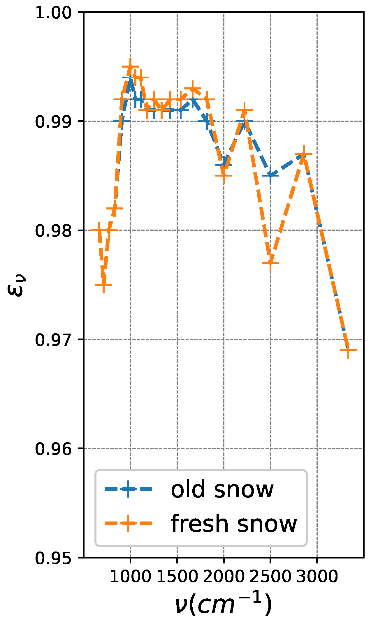
Figure 1. CRTM release versions v1.0 to v2.3.0 a priori snow surface emissivity spectra.
Remotesensing 15 05509 g001
Figure 2. Stacked histograms of longwave TIR microwindow (962.5 cm 1 ) obs − calc obtained from a global snow surface OSE over the time period of 28 July to 30 September 2021, where the “calc” were computed from the existing release version of CRTM (v2.3.0), and “obs” were observations from TIR hyperspectral sounders assimilated within the FV3GFS GSI (FV3GFS_V16) from: (top) the SNPP (orange-red) and NOAA-20 (blue) CrIS in the “afternoon” (01:30, 13:30 local equator crossing time LEXT) ascending orbit, and (bottom) the Metop-B/C (orange-red/blue) IASI in the “morning” (09:30, 21:30 LEXT) descending orbit.
Remotesensing 15 05509 g002
Figure 3. Snow surface emissivity spectra calculated based on the WW80 snow albedo model, Equations (5) and (7), for snow particle radius r = 200   μ m and zenith observing angles θ o = 0 , 30 , 45 , 60 , 75 . The figure aspect ratio, x and y axes, and choice of θ o and r are meant to duplicate visually the results published by Ref. [35] (Figure 1b, op. cit.).
Remotesensing 15 05509 g003
Figure 4. Emissivity particle size dependence at θ o = 10 . The (top) and (bottom) rows show the particle size dependencies in terms of log-r (radius) and log- χ (size parameter), respectively, with these defined by the mean of the radii ranges for snow types reported in Salisbury et al. [51], namely, frost, fresh, or newly fallen snow, and medium and coarse granular snow. The left column shows the results from the WW80 model and the right column shows field-measurements from ECOSTRESS [29,51], with the circles plotted at r = 1000   μ m denoting the flat surface emissivities defined as ϵ ν 1 ρ ν , where ρ ν is the unpolarized Fresnel reflectance.
Remotesensing 15 05509 g004
Figure 5. Fractional non-Fresnel reflective surface areas, η s or 1 η ρ . The blue line/circles depict the values derived by Hori et al. [53] in their “semi-empirical” model, 1 η ρ ; the red line/asterisks depict the values interpreted as surface area reflecting as a multiple-scattering layer, η s , extrapolated in log-r space to smaller snow grain sizes where emissivity is observed to behave in this manner according to the WW80 Mie-scattering model.
Remotesensing 15 05509 g005
Figure 6. As Figure 2, except calc, which are derived from CRTM v2.3.0 using a subset ( θ o = 10 , 60 , and r = 200   μ m) of the physical snow emissivity model LUT (v1, based only on the WW80 albedo model), hard-coded into the GSI.
Remotesensing 15 05509 g006
Figure 7. TIR snow/ice model spectral emissivity calculations versus ECOSTRESS laboratory measurements [29,51] for an observer zenith angle θ o = 10 . The (top) row shows the snow grain size dependencies in log-r space (x-axes) for a sample of 6 monochromatic channels within the TIR spectral windows ( ν = 740, 840, 900, 980, 1160, 2620 cm 1 ), and the (bottom) row shows the corresponding spectral dependencies for a sample of 6 snow grain sizes corresponding to those reported in Ref. [51] ( r = 5, 10, 30, 212.5, 750, and 1000 μ m). The four columns from (left) to (right) show the results of the (1) H15 “semi-empirical” model [53]; (2) the WW80 albedo model [31]; (3) the hybrid physical model, Equation (13); and (4) laboratory measurements from the ECOSTRESS/ASTER library [29,51].
Remotesensing 15 05509 g007
Figure 8. Similar to the top row of Figure 7 but showing TIR snow/ice model spectral emissivity calculations (for a different set of monochromatic channels spanning the lonwave TIR) as a function of linear-r ( μ m) versus multi-angular field measurements of snow cover with median particle sizes r 35   μ m taken from Hori et al. [52]. The columns are arranged as in Figure 7, with emissivity models H13, WW80, and hybrid physical model, shown in the left three columns, and the field measurements in the rightmost column; the rows are arranged from top to bottom, according to zenith observing angles θ o = 30 , 45 , 60 , 75 .
Remotesensing 15 05509 g008
Figure 9. As Figure 8, but showing TIR spectral dependencies on the x-axes.
Remotesensing 15 05509 g009
Table 1. Measured Mean Sizes of Snow Grains ( μ m) During Metamorphosis (From Yosida, 1962 [50]).
# of Days after
Snow Deposition
Mean Length
¯ ( μ m)
Mean Radius
r ¯  ( μ m)
Mean Constriction
w ¯ ( μ m)
12004550
51904550
92606080
1543080100
24600110140
31570130160
Lengths () were defined to be the lengths between the extremities of ice crystals; radii (r) were defined as the thickness of the snow grains at their thickest portions; and constriction widths (w) were defined as the thickness at the narrowest portion [50].
Table 2. Hori et al. [53] Snow Model Specular Fractions ( η ρ ) for Particle Sizes.
Particle Size, r ( μ m) η ρ Snow Morphology
MedianRange
3520–500.22fine dendrite snow
300150–5500.29medium granular snow
40025–5000.41coarse-grained snow
550400–7500.53sun crust
≳1000 (flat) 0.95bare ice
Table 3. Snow/Ice Surface TIR Emissivity Model LUTs.
Model θ o ν (cm 1 )Grain Size, rT (K)
Original CRTM a prioriN/A666–3333“fresh” and “aged”N/A
(CRTM release versions v1.0 to v2.3.0)
WW80 physical model0–75 600–30005–1000 μ m230–270
(CRTM v3, snow emissivity v1.0)
Hybrid physical model0–75 50–30001–1000 μ m230–270
(CRTM v3, snow/ice emissivity v1.1)
N/A = not applicable.
Disclaimer/Publisher’s Note: The statements, opinions and data contained in all publications are solely those of the individual author(s) and contributor(s) and not of MDPI and/or the editor(s). MDPI and/or the editor(s) disclaim responsibility for any injury to people or property resulting from any ideas, methods, instructions or products referred to in the content.