Article

A Space–Time–Range Joint Adaptive Focusing and Detection Method for Multiple Input Multiple Output Radar

1
Marine Target Detection Research Group, Naval Aviation University, Yantai 264001, China
2
92337 Troop, PLA, Dalian 116000, China
*
Author to whom correspondence should be addressed.
Remote Sens. 2023, 15(18), 4509; https://doi.org/10.3390/rs15184509
Submission received: 30 July 2023 / Revised: 8 September 2023 / Accepted: 10 September 2023 / Published: 13 September 2023
(This article belongs to the Special Issue Advanced Array Signal Processing for Target Imaging and Detection)

Abstract

:
The Multiple Input Multiple Output (MIMO) radar, as a new type of radar, emits orthogonal waveforms, which provide it with waveform diversity characteristics, leading to increased degrees of freedom and improved target detection performance. However, it also poses challenges such as difficulty in meeting higher data demand, separating waveforms, and suppressing the multidimensional sidelobes (range sidelobes, Doppler sidelobes, and angle sidelobes) of targets. Phase-coded signals are frequently employed as orthogonal transmission signals in the MIMO radar. However, these signals exhibit poor Doppler sensitivity, and the intra-pulse Doppler frequency shift can have an impact on the effectiveness of the matching filtering process. To address the aforementioned concerns, this paper presents a novel approach called the Space–Time–Range Joint Adaptive Focusing and Detection (STRJAFD) method. The proposed method utilizes the Mean Square Error (MSE) criterion and integrates spatial, temporal, and waveform dimensions to achieve efficient adaptive focusing and detection of targets. The experimental results demonstrate that the proposed method outperforms conventional cascaded adaptive methods in effectively addressing the matching mismatch issue caused by Doppler frequency shift, achieving super-resolution focusing, possessing better suppression effects on three-dimensional sidelobes and clutter, and exhibiting better detection performance in low signal-to-clutter ratio and low signal-to-noise ratio environments. Furthermore, STRJAFD is unaffected by coherent sources and demands less data.

1. Introduction

Amidst the continuously evolving electromagnetic environment, where the cluttered background and target characteristics are becoming increasingly complex and diverse, radar systems face numerous challenges, and the difficulty of detecting targets is also on the rise [1]. The fixed transmission waveforms and operating modes utilized by conventional radar systems exhibit limited adaptability to the changing detection requirements in complex operational environments. Hence, it is crucial to investigate and advance novel radar systems and approaches to target detection [2,3].
The Multiple Input Multiple Output (MIMO) radar, as a new type of radar [4,5], employs orthogonal waveforms for achieving waveform diversity. Its versatile operational capability enables omnidirectional coverage of the airspace [6]. This not only enhances the degree of freedom and spatial resolution and expands the dimension of signal processing, but also benefits the performance of object detection [7].
The initial step in signal processing for the MIMO radar involves the separation of waveforms, which is facilitated by their orthogonality. This is followed by spatial and temporal processing, and ultimately leads to the detection of targets. The successful implementation of waveform separation in MIMO radar systems primarily depends on good orthogonal waveforms and the application of efficient filtering techniques. As the most frequently employed form of MIMO radar orthogonal waveform, the phase-coded waveform exhibits a distinct ambiguity function graph resembling a pushpin and does not suffer from range–Doppler coupling issues [8,9]. However, it is sensitive to Doppler frequency shifts, and the higher the Doppler frequency, the worse the matching filtering effect. Regarding the Doppler sensitivity issue of phase-coded signals, references [10,11] have proposed corresponding Doppler compensation methods, but both require target Doppler estimation, and the compensation effect in practical applications is not ideal. Currently, the commonly used waveform separation filtering methods include matched filtering and adaptive pulse compression, where the performance of matched filtering mainly depends on the performance of orthogonal waveforms [12]. Adaptive pulse compression, as an improved method of matched filtering, can adaptively estimate the filter weights of each distance unit and waveform, improving the separation level of waveforms [13]. However, its performance depends on the appropriate number of iterations, which requires consideration of the degree of contrast between strong and weak scatterers, thereby posing a challenge in the selection process.
Traditional spatial and temporal processing methods include beamforming, pulse accumulation, and Space–Time Adaptive Processing (STAP) [14,15], as well as the Iterative Adaptive Approach (IAA) [16,17]. STAP is an adaptive clutter suppression method that combines the spatial and temporal domains. This approach has been proven to yield significant improvements in clutter suppression and target separation capabilities. The STAP technique in the MIMO radar increases the degree of freedom, which is beneficial for improving the processing performance [18]. However, the estimation of the covariance matrix needs to meet the Reed I S, Mallett J D, Brennan L E (RMB) criterion [19], requiring a large number of independent and identically distributed samples, which can lead to problems such as large amount of computation and long operation time. Although methods such as those in [20,21] for dimensionality reduction and rank reduction have been continuously proposed, the fundamental resolution of this problem has not yet been achieved. For IAA, it can achieve effective angle Doppler imaging after matched filtering, thereby achieving Space–Time joint processing [22].
For MIMO radar systems, two commonly employed pre-detection methods are Matched Filtering–Beam Forming–Discrete Fourier Transform (MF-BF-DFT) [23] and Adaptive Pulse Compression–Beam Forming–Discrete Fourier Transform (APC-BF-DFT) [24]. The MF-BF-DFT method is the simplest and most convenient method for engineering applications, while the APC-BF-DFT method improves the effect of suppression on range sidelobes compared to the former method but increases computation complexity. However, the above two methods have poor suppression effects on three-dimensional (3D) sidelobes, and do not have clutter and noise suppression capabilities, so that the effect after cascaded processing does not meet good expectations. Adaptive Pulse Compression–Iterative Adaptive Approach–Space–Time Adaptive Processing (APC-IAA-STAP) [22,25] is a new adaptive iterative processing method that has been proposed in recent years. Compared with the previous two methods, it has better clutter and noise suppression capabilities and can achieve good suppression of 3D sidelobes. However, this method is a cascaded two-step iterative processing method, which makes it challenging to choose the appropriate number of iterations for each stage. Additionally, as it is still a cascaded method, it may not provide adequate performance for the overall suppression of 3D sidelobes. Therefore, further improvements are necessary to enhance its processing performance.
In light of the aforementioned scenario, this study presents a novel approach called the Space–Time–Range Joint Adaptive Focusing and Detection (STRJAFD) method. The proposed method utilizes the Mean Squared Error (MSE) criterion and integrates spatial, temporal, and waveform dimensions. The aforementioned approach has several advantages:
(1)
The technique effectively improves the matching mismatch problem caused by Doppler frequency shift;
(2)
The technique has good clutter- and noise-suppression effects;
(3)
The technique has good sidelobe-suppression effects (range sidelobes, Doppler sidelobes, and angle sidelobes);
(4)
The technique is capable of efficiently segregating waveforms;
(5)
The technique is not affected by coherent source cancellation;
(6)
The technique necessitates a minimal amount of data.
In this paper, a Space–Time–Range Joint Adaptive Focusing and Detection method is proposed to suppress 3D sidelobes and clutter, and improve detection performance with cluttered and noisy backgrounds. The content of this paper is organized as follows. In Section 2, the construction of the MIMO radar Space–Time–Range echo signal model is discussed; meanwhile, the principle and process of the Space–Time– Range Joint Adaptive Focusing and Detection method are introduced. In Section 3, we discuss the experimental simulations in different scenarios that were conducted to demonstrate STRJAFD’s feasibility and effectiveness. Section 4 analyzes the reasons why the proposed method is superior to traditional cascaded adaptive methods. Section 5 summarizes the conclusions drawn from this study and outlines future prospects.
The main contribution of this study includes four aspects. Firstly, a Space–Time–Range Joint Adaptive Focusing and Detection algorithm is proposed, which is a three-dimensional joint adaptive processing method and can achieve high-resolution focusing. Secondly, the proposed method indirectly improves the matching mismatch issue caused by Doppler frequency shift through the design of expected signals, solving the problem that matching filtering and adaptive pulse compression are difficult to solve in the distance dimension, compared to conventional cascaded adaptive methods (MF-BF-DFT, APC-BF-DFT, and APC-IAA-STAP). Thirdly, through the effective design of the covariance matrix and the iterative filtering processing based on the MSE criterion, the proposed method can effectively suppress three-dimensional sidelobes in the distance, space, and Doppler dimensions, and its sidelobe suppression effect is far superior to the cascaded single dimension adaptive processing method (MF, APC, BF, and DFT). And, it can simultaneously suppress clutter and noise, which cannot be achieved by beamforming and Doppler processing, and the suppression effect of three-dimensional joint processing is also better than that of two-dimensional joint processing (STAP). Fourthly, a relatively complete Space–Time–Range three-dimensional echo signal model of the MIMO radar was established, taking into account the influence of Doppler frequency shift on phase-encoded signals.

2. Space–Time–Range Joint Adaptive Focusing and Detection Method

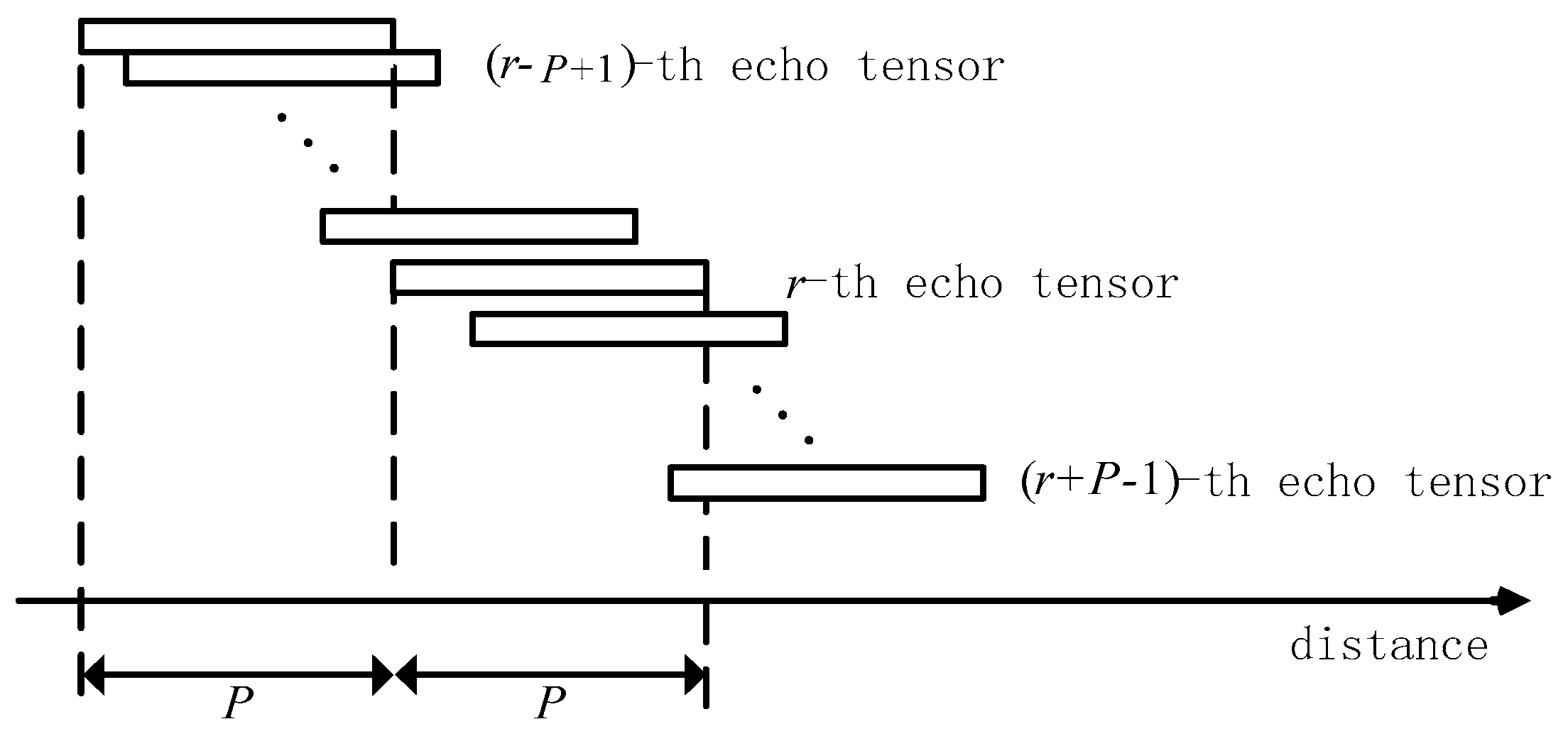
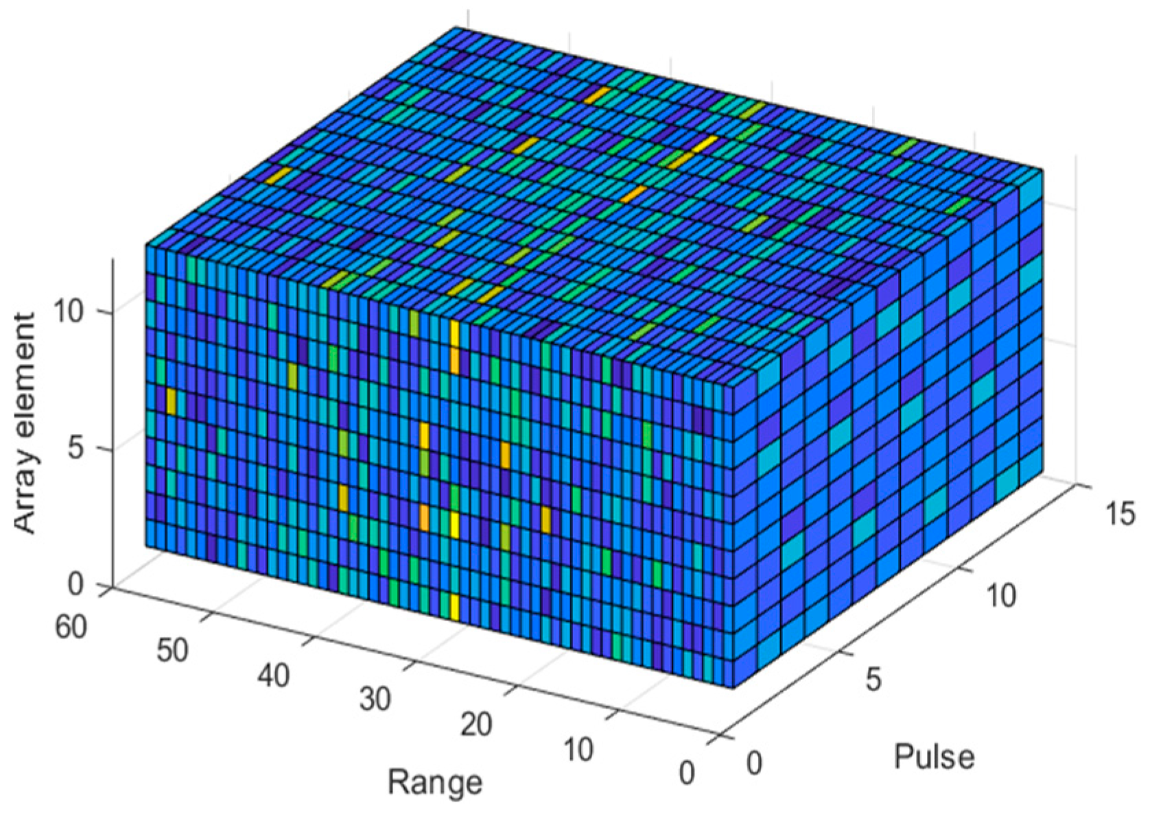
2.1. Space–Time–Range Model of MIMO Radar Echo Signal

Assuming that the MIMO radar is an equidistant linear array consisting of M transmitting elements and N receiving elements, with a carrier frequency of f 0 , a wavelength of λ , a distance between receiving elements of d r = λ / 2 , a distance between transmitting elements of d t = N d r , a pulse repetition period of T, and a carrier speed of v 0 , and assuming that the orthogonal encoded signals transmitted are all narrowband signals, then the transmitted signals of each transmitting element are s 1 ( t ) ,   s 2 ( t ) ,     , s M ( t ) , denoted as S ( t ) = s 1 ( t ) , s 2 ( t ) ,     , s M ( t ) T , and P is the encoding length of the signal within one pulse period.
Assuming that the target is non fluctuating and located in the r-th distance unit, with a direction of θ and a speed of v t , then the echo signal model of the single pulse is as described in Equation (1).
X ( t ) = ξ ( r , θ , f d ) b θ a T θ S ( t ) e j 2 π f d t   ,
where ξ ( r , θ , f d ) is the true complex amplitude of the target with direction θ and Doppler frequency f d in the distance unit r , and a θ , b θ , and f d are the emission guidance vector, reception guidance vector, and Doppler frequency information of the target; their specific formulae are shown in Equations (2)–(4), respectively.
f d = 2 ( v 0 sin θ + v t ) λ ,
a θ = [ 1 ,   e j 2 π λ d t sin θ ,   e j 2 π λ 2 d t sin θ ,   , e j 2 π λ ( M 1 ) d t sin θ ] T ,
b θ = [ 1 ,   e j 2 π λ d r sin θ ,   e j 2 π λ 2 d r sin θ ,   , e j 2 π λ ( N 1 ) d r sin θ ] T ,
After analog-to-digital conversion, a discrete target echo signal model is obtained, as seen in Equation (5).
X l = ξ ( r , θ , f d ) b θ a T θ S e j 2 π ( l 1 ) f d T l = 1 , 2 , , L ,
where S = [ s 1 s f ,   s 2 s f ,     , s M s f ] T M × P , s f = e j 2 π 1 P f d T , e j 2 π 2 P f d T , , e j 2 π f d T T , and [ s 1 ,   s 2 ,     , s M ] is the orthogonal phase-encoding waveform used in the paper.
The echo signals of the L pulses of the target located in the distance unit r are described in (6).
X r = ξ ( r , θ , f d ) b θ a T θ S g f d       = ξ ( r , θ , f d ) b θ S T a θ g f d ,
where g ( f d ) = [ 1 ,   e j 2 π f d T ,   e j 2 π 2 f d T ,   , e j 2 π ( L 1 ) f d T ] T , is the Kronecker product, and is the outer product of a tensor.
If there are K targets with different directions and Doppler frequencies in the distance unit r , then the above Equation (6) becomes Equation (7).
X r = j = 1 K ξ ( r , θ j , f d j ) b θ j S T a θ j g f d j ,
where ξ ( r , θ j , f d j ) is the true complex amplitude of the target with direction θ j and Doppler frequency f d j in the distance unit r , and a θ j , b θ j , and f d j are the emission guidance vector, reception guidance vector, and Doppler frequency information of the j-th target, j = 1 ,   2 ,     ,   K .
Assuming that each distance unit is affected by the clutter scattering points of different surrounding azimuth units, based on this, the spatial angle π / 2 ,   π / 2 is evenly divided into N c parts, and the true complex amplitude of the clutter scattering bodies in each distance azimuth unit is recorded as ξ ( r , θ i ) . At the same time, it is assumed that it follows a complex Gaussian distribution with a mean of 0 and a variance of σ c 2 , and that they are statistically independent of each other [14]. At last, the clutter model is described in Equation (8).
C r = i = 1 N c ξ ( r , θ i ) b θ i S T a θ i g f d i ,
where f d i = 2 ( v 0 sin θ i + v i ) λ , and v i represents the velocity of the scatterer with an azimuth of θ i relative to the carrier, which is set to 0 in this paper. At this point, the clutter Doppler is a function of azimuth θ i . As a result, the clutter Doppler is proportional to the normalized angle of d r sin θ i λ and has a constant proportional coefficient.
When there is a target in the r-th distance unit, the Space–Time–Waveform echo tensor Y r P × N × L is as described in Equation (9).
Y r = X r + C r + N r ,
When there is no target in the r-th distance unit, the Space–Time–Waveform echo tensor Y r P × N × L is as described in Equation (10).
Y r = C r + N r ,
where C r is the clutter in the r-th distance unit and N r is the noise in the r-th distance unit.
In fact, the echo data of each distance unit come from the superposition of P waveform echo data, and the specific superposition mode is shown in Figure 1.
Assuming that there are a total of Q + 2 P 1 Space–Time–Waveform echo tensors, the MIMO radar Space–Time–Range signal model Y r P × N × L before matched filtering can be described by Equation (11).
Y r = p = ( P 1 ) P 1 Y r + p   P r Q + P ,
where Y r + p represents the r + p - th Space–Time–Waveform echo tensor. When there is a target in the r + p - th distance unit, the Y r + p is as described in Equation (12); when there is no target in the r + p - th distance unit, the Y r + p is as described in Equation (13).
Y r + p = X r + p + C r + p + N r + p ,
Y r + p = C r + p + N r + p ,
where X r + p is as described in Equation (14) and C r + p is as described in Equation (15).
X r + p = j = 1 K ξ ( r , θ j , f d j ) b θ j J T p S T a θ j g f d j ,
C r + p = i = 1 N c ( r , θ i ) b θ i J T p S T a θ i g f d i ,
where J p is a Stochastic matrix to realize waveform superposition, which is described in Equation (16).
J i , j p = 1 , if i j + p = 0 0 , if i j + p 0 ,
Based on Y r P × N × L , the Space–Time–Range echo data model Y Q × N × L received by the MIMO radar can be constructed, as shown in Figure 2.

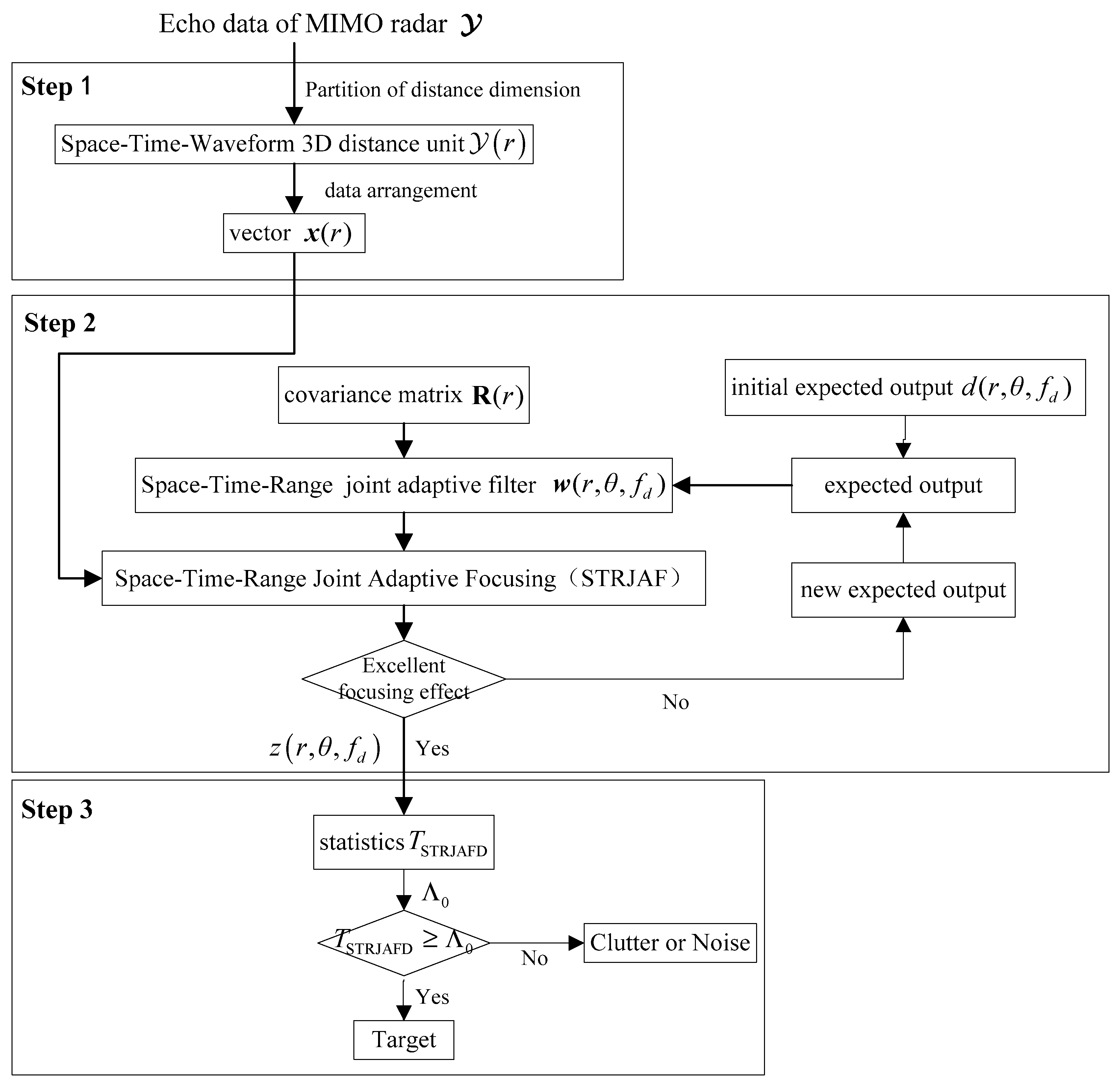
2.2. The Principle of Space–Time–Range Joint Adaptive Focusing and Detection Algorithm

Among the existing array signal processing methods, single-dimensional adaptive processing methods, including beamforming in the spatial domain, coherent integration in the time domain, and matched filtering in the waveform dimension, essentially focus on accumulating energy in each dimension. However, for three-dimensional echo data of the MIMO radar in cluttered and noisy environments, cascaded single-dimensional adaptive processing is prone to forming sidelobes in each dimension. Moreover, there is no clutter and noise suppression function, resulting in the inadequate utilization of the structural information of the three-dimensional echo data, which can easily lead to a poor detection performance under a low signal-to-clutter ratio (SCR) and low signal-to-noise ratio (SNR).
To address this issue, this paper proposes a Space–Time–Range Joint Adaptive Focusing and Detection method based on the Mean Squared Error (MSE) criterion that combines spatial, temporal, and waveform dimensions. Firstly, the Space–Time–Range Joint Adaptive Focusing (STRJAF) is applied to the three-dimensional echo data to improve the matching mismatch caused by Doppler frequency shift and effectively suppress sidelobes. At the same time, it also helps to suppress clutter and noise, thereby enhancing the SCR and SNR. Finally, the test statistics are constructed based on the STRJAF results to achieve target detection.
The target energy in the radar echo data can be analyzed from the perspective of waveform dimension before matched filtering. In the MIMO radar echo, the echo energy of a target is distributed within P (encoding length of waveform) distance units that include its location. Therefore, when processing the received Space–Time–Range 3D echo data tensor Y Q × N × L , this paper divides it into QP + 1 Space–Time–Waveform scale (P × N × L) 3D subtensors Y r P × N × L r = 1 , 2 , , Q P + 1 , using P (encoding length of waveform) as a scale in the distance dimension. These subtensors can be regarded as QP + 1 new “three-dimensional distance units” to ensure that the target energy can be fully contained in a certain “three-dimensional distance unit”. Due to the inability to directly process 3D data, this paper converts the “3D distance unit” Y r P × N × L into a one-dimensional vector x ( r ) P N L × 1 r = 1 , 2 , , Q P + 1 .
The Mean Squared Error (MSE) criterion is a classical adaptive filter optimization criterion. Its core idea is to minimize the Mean Squared Error between the filtered output and the expected output, so as to achieve the purpose of filter optimization.
In actual situations, the target direction and Doppler frequency are unknown. Therefore, this paper uniformly divides the spatial angle π / 2 ,   π / 2 into N s parts, and uniformly divides the normalized Doppler frequency 0.5 ,     0.5 into N f parts, so that the target function based on the MSE criterion is as described in Equation (17).
J r , θ , f d = E y ( r ) d ( r , θ , f d ) 2 = E w ( r , θ , f d ) x ( r ) d ( r , θ , f d ) 2               = w ( r , θ , f d ) H R ( r ) w ( r , θ , f d ) + E d ( r , θ , f d ) 2 w ( r , θ , f d ) H r x d r x d H w ( r , θ , f d ) ,
Among them, x ( r ) is the echo signal of the r-th distance unit, y ( r ) is the output after adaptive filtering, d ( r , θ , f d ) is the expected output of the r-th distance unit when the direction is θ , the normalized Doppler frequency is f d , w ( r , θ , f d ) is the Space–Time–Range joint adaptive filter of the r-th distance unit when the direction is θ , the normalized Doppler frequency is f d , r x d is the correlation vector between the echo signal x ( r ) and the expected output d ( r , θ , f d ) , and R ( r ) is the covariance matrix.
The formula obtained by solving the objective function is described in Equation (18).
w ( r , θ , f d ) = R ( r ) 1 r x d ,
where r x d = x ( r ) d ( r , θ , f d ) * .
The obtained solution reveals that the utilization of the MSE criterion necessitates the availability of a covariance matrix and a predetermined expected output. Consequently, the meticulous design of both the covariance matrix and initial expected output assumes paramount significance.
In this paper, first and foremost, we propose a method to design the initial expected output using the Space–Time–Waveform joint adaptive filter, which is described in Equation (19).
d ( r , θ , f d ) = h ( r , θ , f d ) H x ( r ) h ( r , θ , f d ) H h ( r , θ , f d ) ,
where h ( r , θ , f d ) is the Space–Time–Waveform joint adaptive filter, which is capable of achieving a satisfactory initial result by applying joint adaptive matched filtering in three dimensions (Space, Doppler frequency, and waveform) to the input data, h ( r , θ , f d ) = b θ g f d a T θ S .
To address the matching mismatch caused by intra-pulse Doppler frequency shift, this paper proposes a solution. Instead of directly compensating for it, we will set h ( r , θ , f d ) as the product of the transmit steering vector and the intra-pulse waveform after the intra-pulse Doppler frequency shift, followed by the Kronecker product of the receive steering vector and the Doppler steering vector. This approach effectively eliminates the matching mismatch without direct compensation for the intra-pulse Doppler frequency shift. By designing the initial expected output in this way, we could achieve an indirect improvement in the matching mismatch.
Then, we designed the covariance matrix. The covariance matrix of each distance unit was designed to the sum of the covariance matrices of 2P − 1 distance units (including this distance unit) in all Doppler frequency and spatial directions, which is described in Equation (20).
R ( r ) = p = ( P 1 ) P 1 θ = π / 2 π / 2 f d = P R F / 2 P R F / 2 x ( r + p , θ , f d ) x ( r + p , θ , f d ) H ,
The energy output after filtering is described in Equation (21).
z r , θ , f d = y ( r ) H y ( r )   = w ( r , θ , f d ) H x ( r ) H w ( r , θ , f d ) H x ( r ) ,
Finally, iterative processing is performed on the filtered output. We used the filtered output z r , θ , f d as the expected output d ( r , θ , f d ) for the next iteration input, iterating until the desired filtered output had been obtained. And, the output at this point was the final Space–Time–Range Joint Adaptive Focusing output.
In this paper, the Space–Time–Range data used were Array Element–Pulse–Range data, which can be considered equivalent to Beam–Pulse–Range data, Array Element–Doppler–Range data, and Beam–Doppler–Range data. The difference lies in whether beamforming or Doppler transformation is performed. Therefore, the Space–Time–Range Joint Adaptive Focusing method proposed in this paper actually includes four sub methods: Array Element–Pulse–Range Joint Adaptive Focusing, Beam–Doppler–Range Joint Adaptive Focusing, Array Element–Doppler–Range Joint Adaptive Focusing, and Beam–Doppler–Range Joint Adaptive Focusing. These four sub methods are essentially equivalent, and so the remaining three sub methods will not be elaborated upon in the paper.
After achieving Space–Time–Range Joint Adaptive Focusing, the problem of MIMO radar target detection can be expressed as in Equation (22).
H 0 : z r = z c l u t t e r r + z n o i s e r H 1 : z r = z t a r g e t r , θ , f d + z c l u t t e r r + z n o i s e r ,
Based on this, the test statistics are constructed in Equation (23).
T STRJAFD = z r H 0 H 1 Λ 0 ,
where Λ 0 is the detection threshold.
Figure 3 is the flow chart of the STRJAFD method. Based on the flow chart, we summarize and sort out the steps of the STRJAFD method.
Step 1: MIMO radar echo data processing. ① Receive MIMO radar Space–Time–Range three-dimensional echo data Y Q × N × L ; ② divide it into multiple Space–Time–Waveform “three-dimensional distance units” Y r P × N × L r = 1 , 2 , , Q P + 1 ; ③ convert the “three-dimensional distance units” into one-dimensional vector data x ( r ) P N L × 1 .
Step 2: The Space–Time–Range Joint Adaptive Focusing based on the MSE criterion. ① Calculation of initial expected output d ( r , θ , f d ) and covariance matrix R ( r ) ; ② calculation of Space–Time–Range joint adaptive filter w ( r , θ , f d ) = R ( r ) 1 r x d ; ③ Space–Time–Range Joint Adaptive Focusing for echo data x ( r ) P N L × 1 ; ④ judgment on whether the output of the focus is satisfactory. If the focusing result is excellent, output it directly as the final result. If the focusing result is not particularly excellent, use this focusing result as the expected output for the next iteration and continue the iterative operation until an excellent focusing effect is achieved. (In fact, this step is an iterative process. After setting the number of iterations, it is assumed that the results before reaching the number of iterations are not satisfactory).
Step 3: Target detection. ① Build detection statistics based on focused output; ② judge whether to exceed the threshold; ③ output of detection results.

3. Results

In this section, we firstly investigate the focusing performance of STRJAF on multiple targets in a cluttered background (background for ground detection) and pure noise background (background for airspace detection), respectively. The purpose is to assess the method’s ability to suppress sidelobe, clutter, and noise in both environments. Additionally, it compares the proposed method with the existing cascaded methods. Subsequently, the impact of intra-pulse Doppler frequency shift on the STRJAF method is examined. Finally, the detection effect under a cluttered background is experimentally verified and compared with existing cascaded methods.

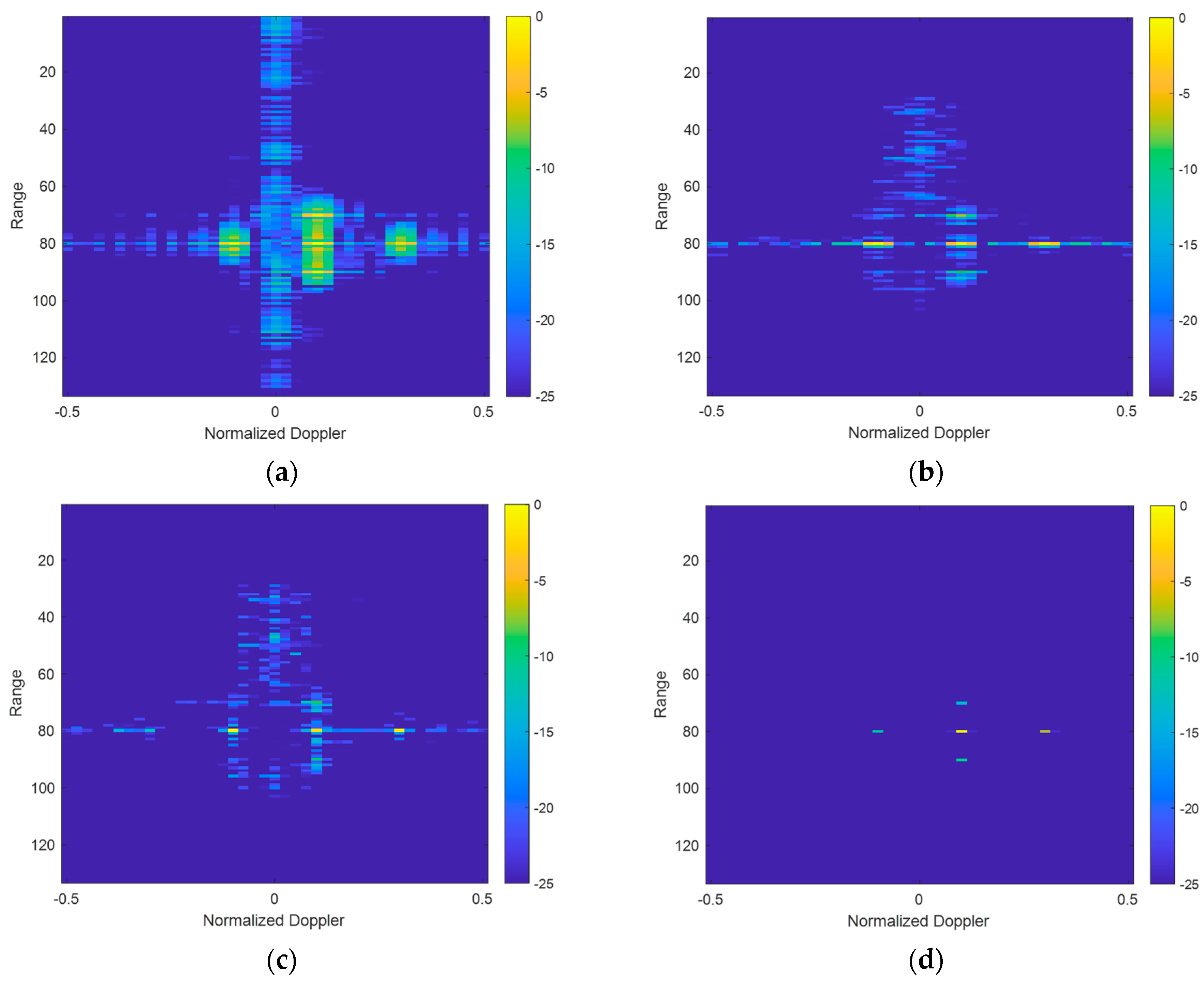
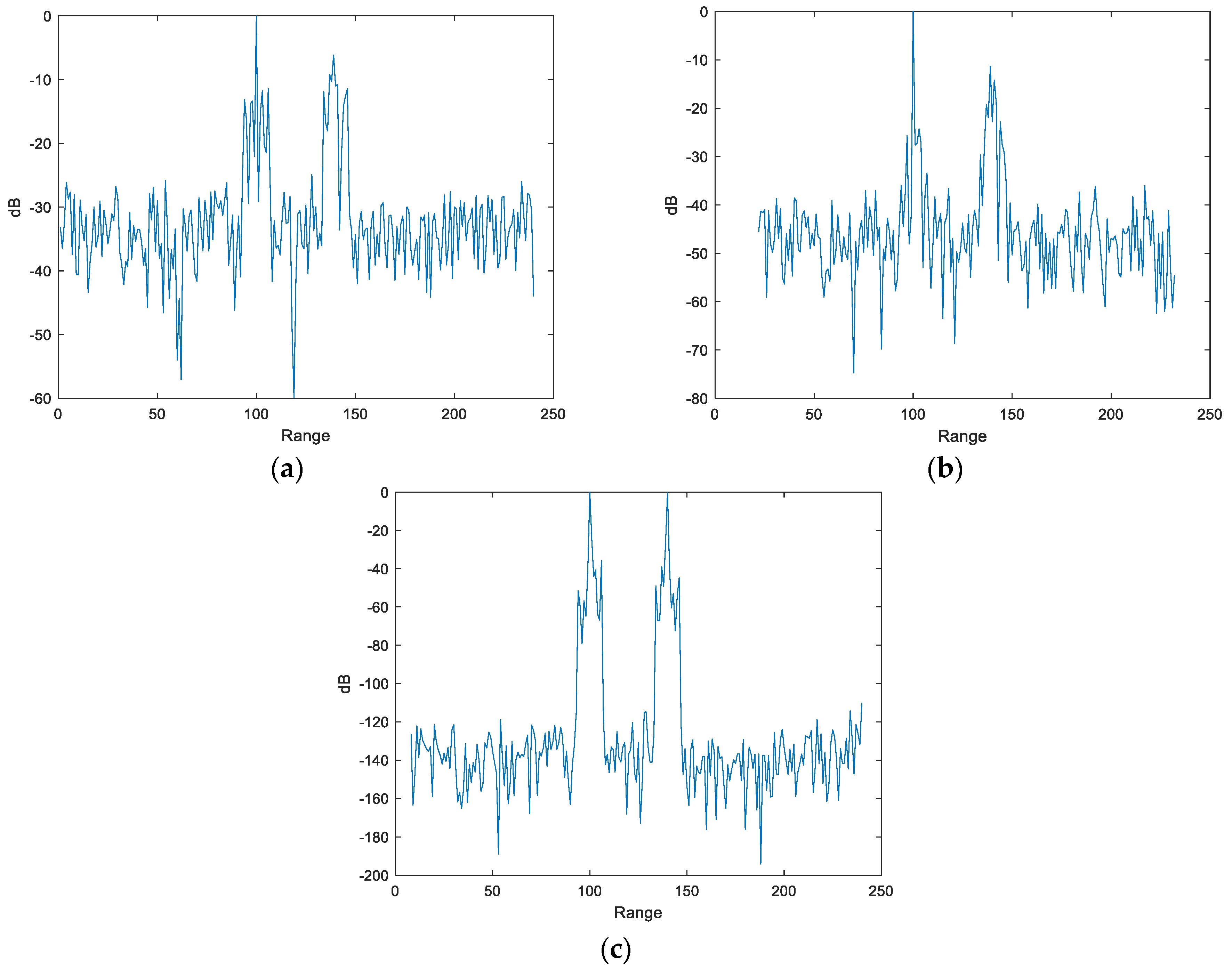
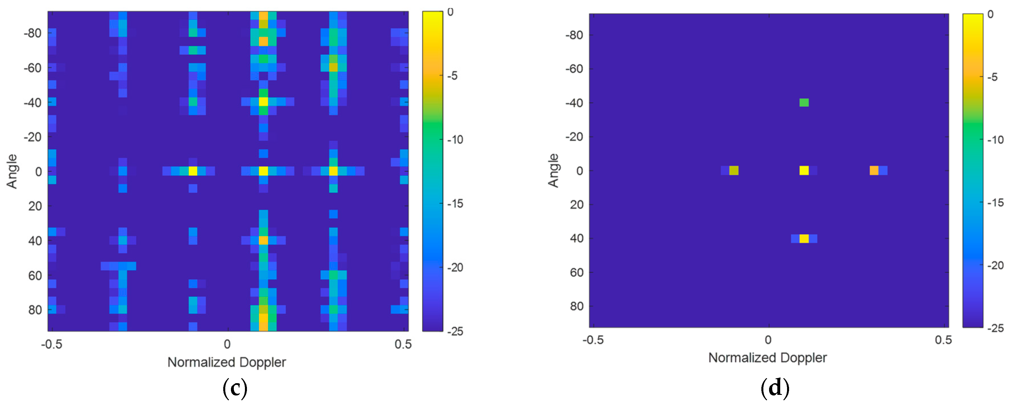
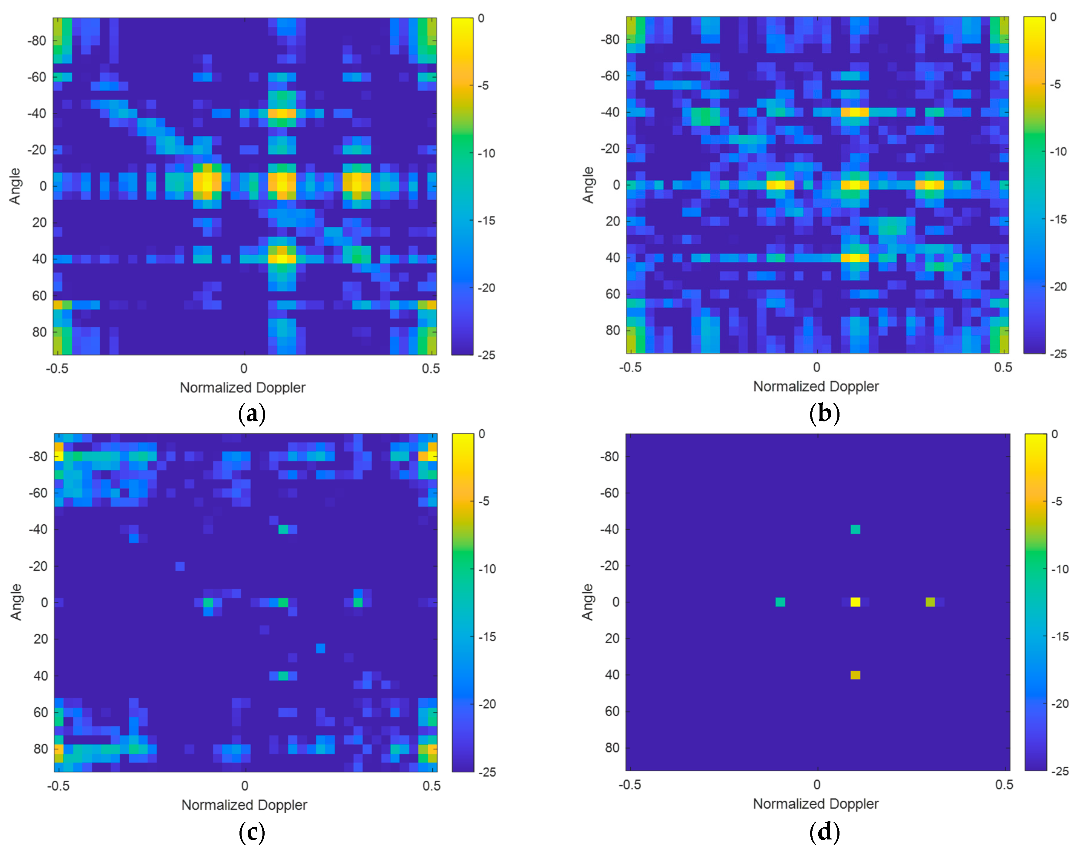
3.1. Focusing Results with Cluttered and Noisy Backgrounds

Assuming that the number of transmitting Array Elements is 4, the number of receiving Array Elements is 8, and the number of pulses is 16, the orthogonal polyphase-encoding sequence is used as the intra-pulse encoding waveform, and the waveform encoding length is 8. The angle–Doppler–distance information of the simulation target was set as is shown in Table 1.
In this paper, we compare the proposed method with three other approaches: MF-BF-DFT, APC-BF-DFT, and APC-IAA-STAP. The target’s signal-to-noise ratio was set to 20 dB, and the clutter-to-noise ratio (CNR) was set to 0 dB. The number of iterations for APC and IAA were both set to 4. Furthermore, the number of angle units was set to 37, the number of Doppler units was set to 41, and the number of distance units was set to 140.

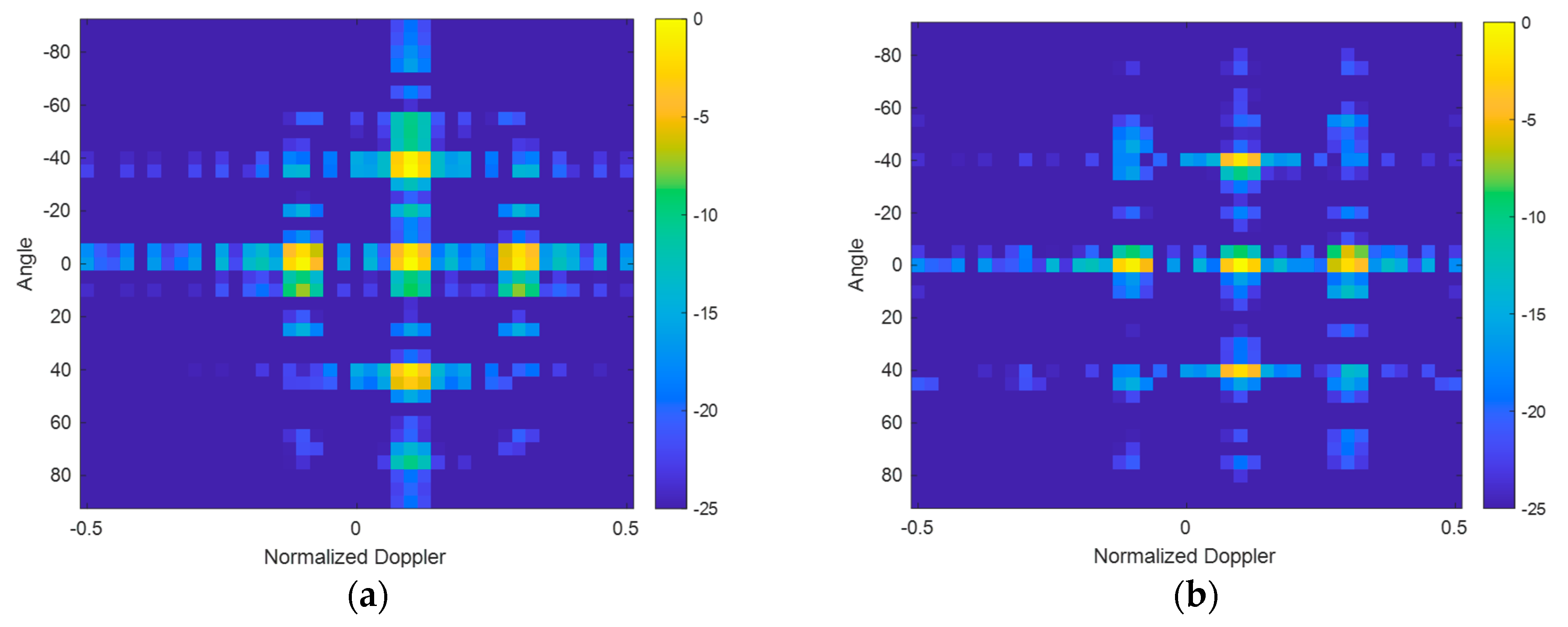
3.1.1. Focusing Results with Noisy Background

Firstly, under the background for airspace detection (noisy background), this paper selected Targets 1–7 to study the focusing imaging effects of various methods in the angle–normalized Doppler dimension and the angle–distance dimension. The experimental results are shown in Figure 4 and Figure 5, respectively.
The experimental results demonstrate that the proposed 3D joint focusing method STRJAF performs with excellent suppression capabilities for three-dimensional sidelobes (range sidelobe, Doppler sidelobe, and angle sidelobe) under a noisy background. Furthermore, it can achieve super-resolution and boasts exceptional noise reduction abilities. The focusing effect of the proposed method is slightly superior to that of the semi-cascaded and semi-joint method “APC-IAA-STAP”, and significantly surpasses traditional cascading methods such as “MF-BF-DFT” and “APC-BF-DFT”.

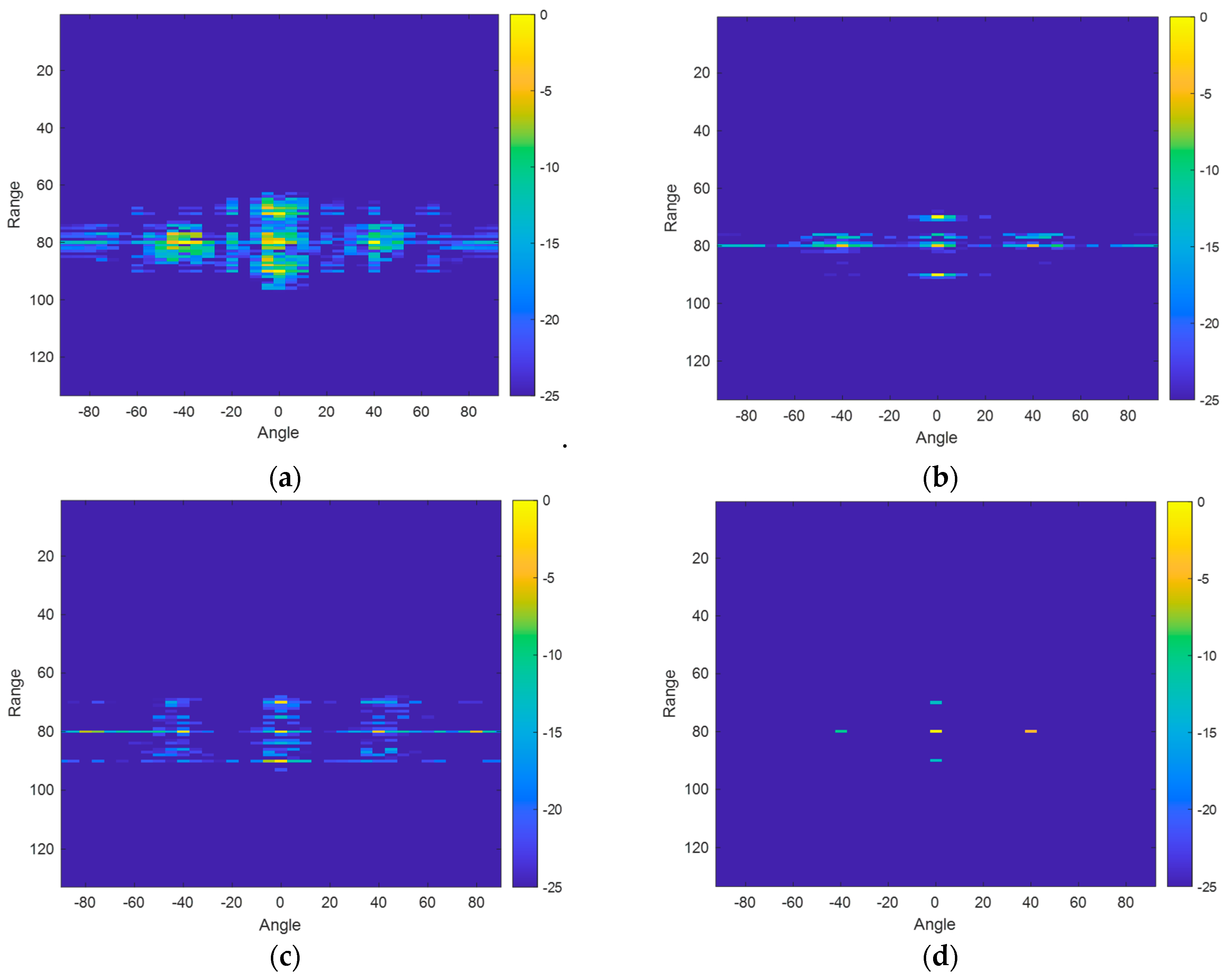
3.1.2. Focusing Results with Cluttered Background

Under the background for ground detection (cluttered background), this paper selected Targets 1–5 to study the focusing imaging effects of various methods in the angle–normalized Doppler dimension and the normalized Doppler–range dimension. The experimental results are shown in Figure 6 and Figure 7, respectively.
From the experimental results, it can be seen that under the cluttered background, there are clutter ridges in the diagonal position of the two-dimensional image in the Space–Time dimension. It is obvious that the broadening of the clutter ridges in the cascaded methods (“MF-BF-DFT” and “APC-BF-DFT”) is more severe than that in the semi-cascaded and semi-combined method (“APC-IAA-STAP”). As the SCR decreases, this situation will become more apparent. Meanwhile, the proposed 3D joint focusing method STRJAF still has good clutter suppression and focusing effects in cluttered environments, being significantly superior to traditional cascaded methods.
In summary, the proposed STRJAF method can effectively suppress clutter and noise and effectively suppress three-dimensional sidelobes for focusing, and has super-resolution ability that is significantly superior to traditional cascading methods, regardless of whether it is a cluttered or noisy background.

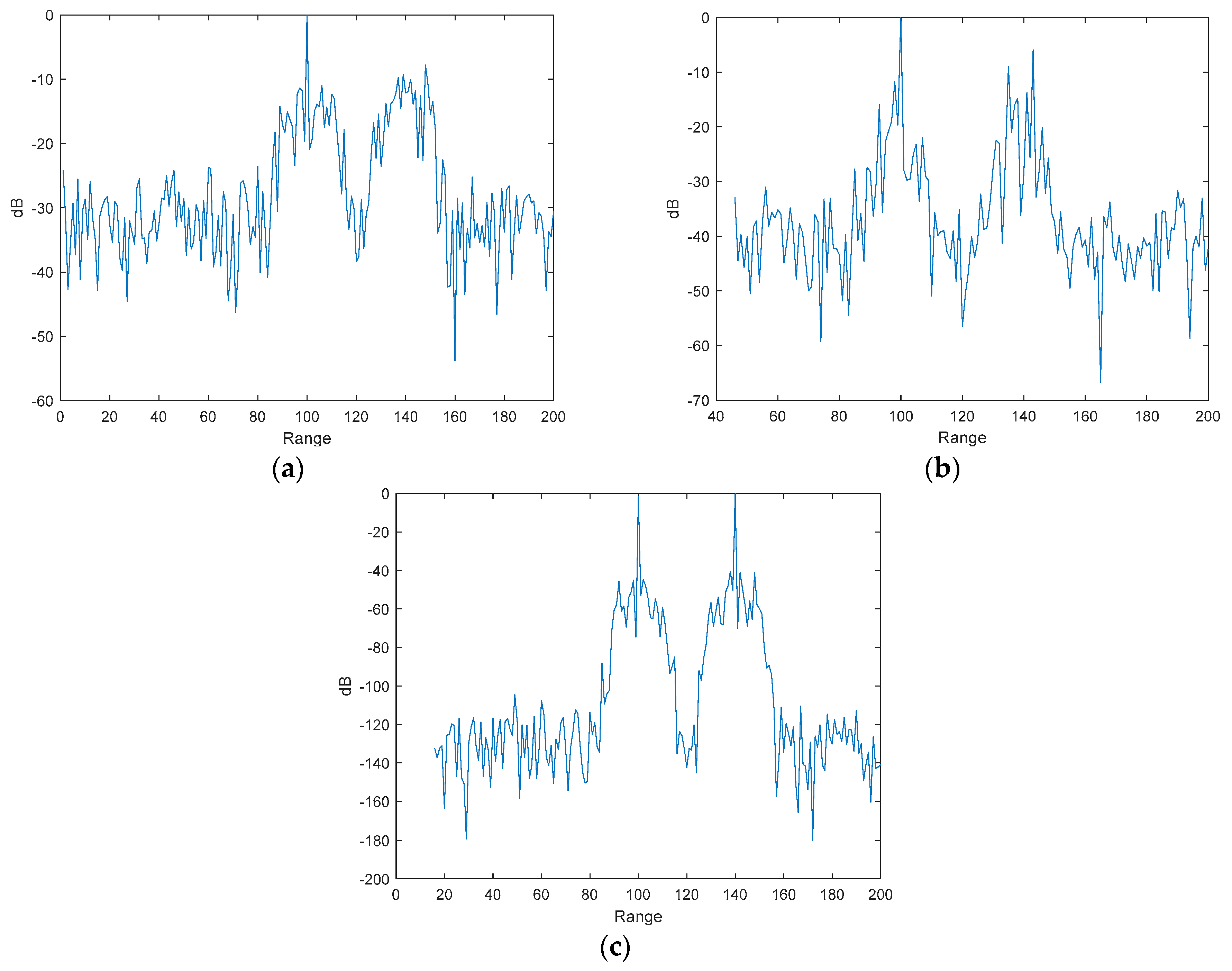
3.2. The Influence of Intra-Pulse Doppler Frequency Shift

In order to study the impact of intra-pulse Doppler frequency shift on the proposed method, this paper selects two targets with an angle, normalized Doppler, and distance units of (0°, 0, 100) and (0°, 1, 140), representing two cases of no intra-pulse Doppler frequency shift and a maximum intra-pulse Doppler frequency shift. We set the number of transmitting Array Elements to 4, the number of receiving Array Elements to 4, the number of pulses to 8, and the SNR to 0 dB. The experimental results after processing with STRJAF and cascading methods under different code length conditions in a noisy background are shown in Figure 8 and Figure 9, respectively.
From the experimental results, it can be verified that when there is intra-pulse Doppler frequency shift, matched filtering and adaptive pulse compression methods are prone to being mismatched in the distance dimension, resulting in a decrease in the effectiveness of matched filtering and pulse compression, which is not conducive to the accumulation of target energy. Moreover, the larger the Doppler frequency shift and the longer the code length of the encoded signal, the more significant the mismatch. The proposed method STRJAF is not affected by the intra-pulse Doppler frequency shift, ensuring the effective accumulation of target energy, which proves the effectiveness of the proposed method in improving the intra-pulse Doppler frequency shift problem.

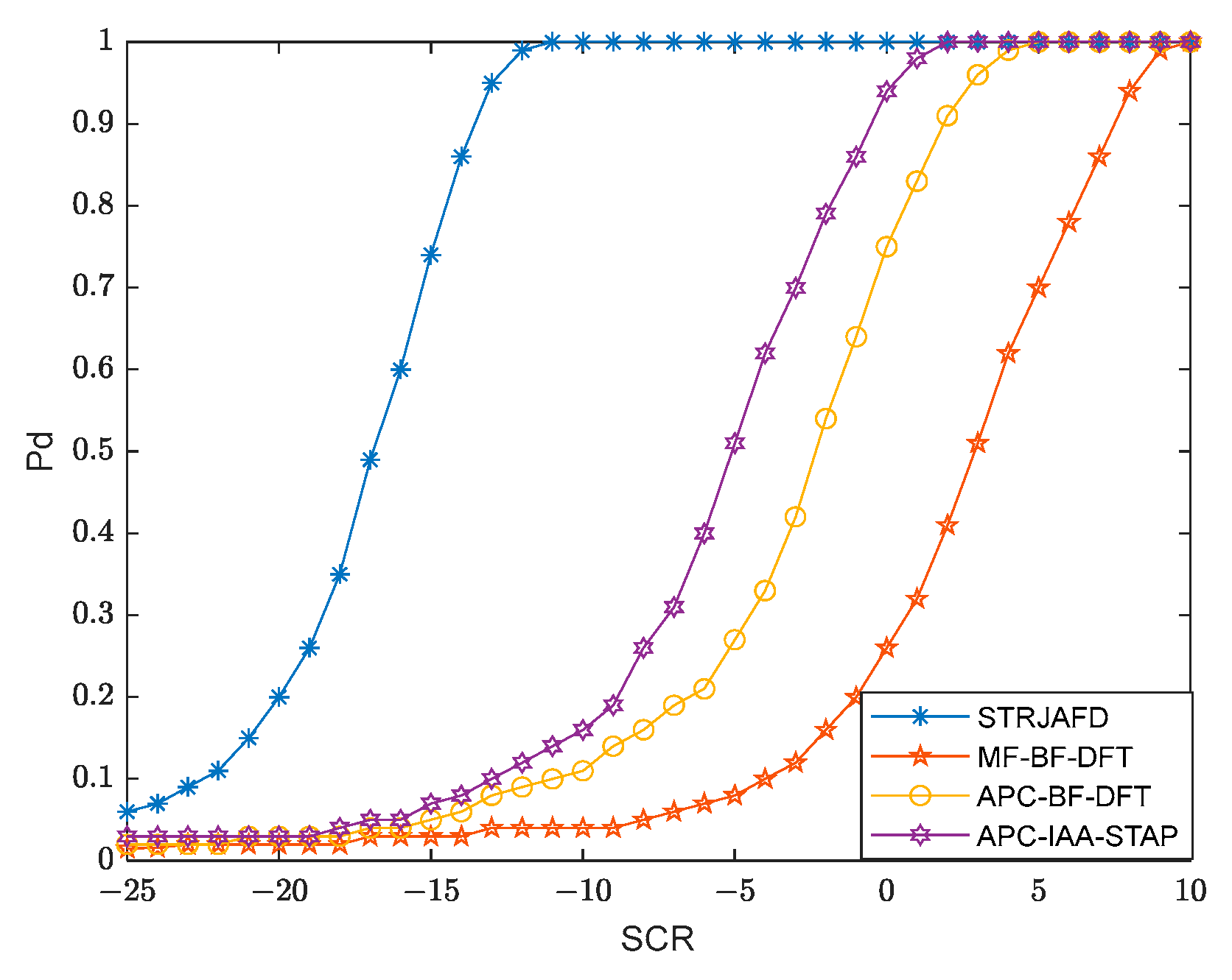
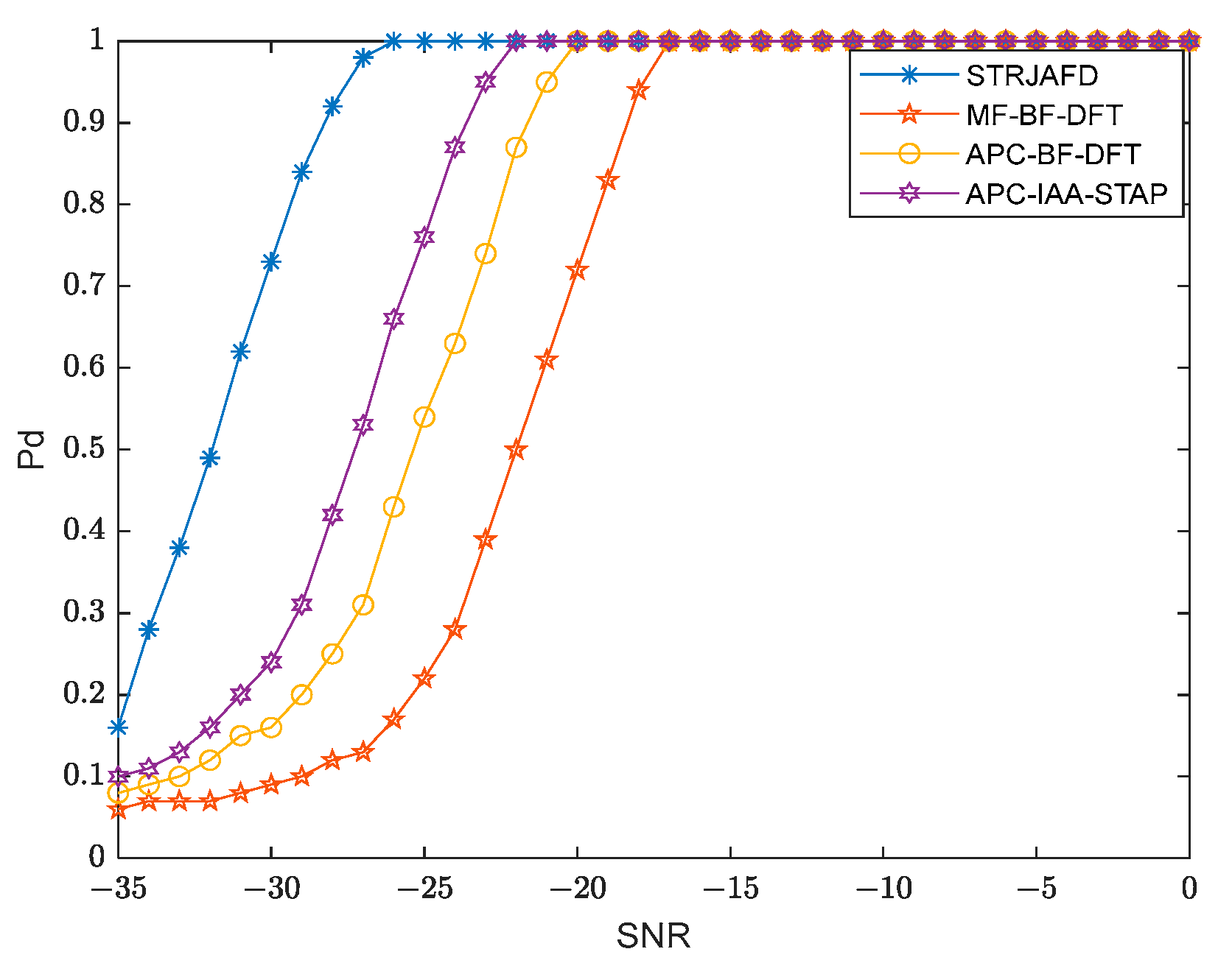
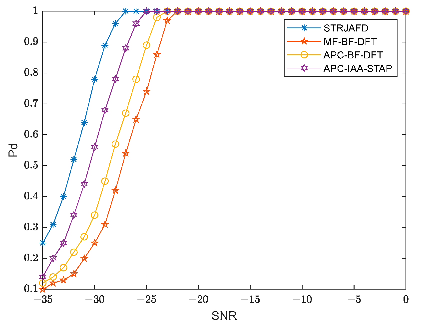
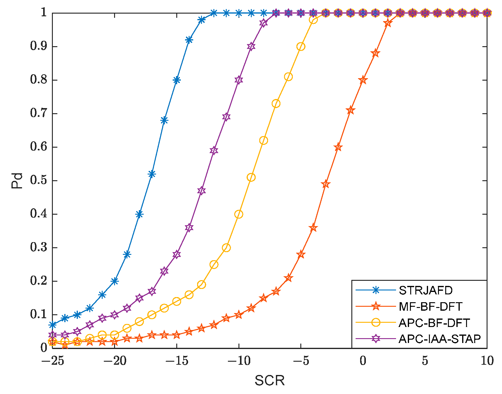
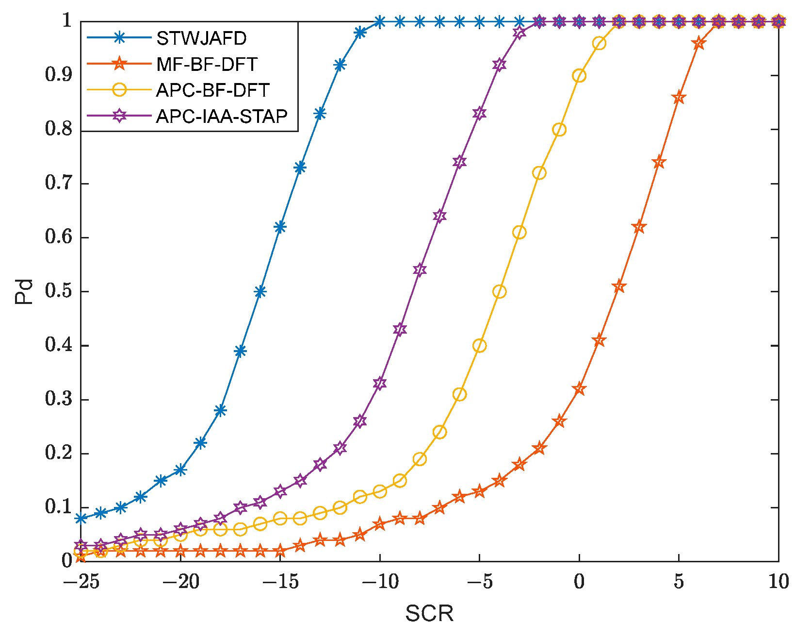
3.3. Detection Results with Noisy and Cluttered Backgrounds

In this section, this paper investigates the detection performance of the proposed method with noisy and cluttered backgrounds and compares it with traditional cascaded processing methods. Assuming that the number of transmitting Array Elements is 4, the number of receiving Array Elements is 4, and the number of pulses is 8, an orthogonal polyphase-encoding sequence is used as the intra-pulse encoding waveform, with a waveform encoding length of 8, and the false alarm rate is set to 10−2. With a cluttered background, the detection probability at each signal-to-clutter ratio was obtained through 1000 simulations. The signal-to-clutter ratio here is defined as the signal-to-clutter ratio before pulse compression and coherent accumulation.

3.3.1. The Effect of Intra-Pulse Doppler Frequency Shift on Detection Performance

Firstly, the impact of intra-pulse Doppler frequency shift on target detection performance was studied under two conditions of Doppler frequency shift and no Doppler frequency shift in the echo signal. At the same time, comparisons were made between three methods, “MF-BF-DFT”, “APC-BF-DFT”, and “APC-IAA-STAP”, using the Constant False Alarm Rate (CFAR) method.
At first, the target detection performance without intra-pulse Doppler frequency shift was studied, and targets with an angle, normalized Doppler, and distance units of (10°, 0, 50) were selected for detection experiments and used as the reference standards. The experimental results are shown in Figure 10 and Figure 11.
Then, the impact of intra-pulse Doppler frequency shift on detection performance with a cluttered background was studied, and targets with an angle, normalized Doppler, and distance units of (10°, 0.5, 50) were selected as experimental targets. The experimental results are shown in Figure 12.
The experimental results show that the detection results of various methods do not differ significantly under the condition of no intra-pulse Doppler frequency shift with a noisy background. However, with a cluttered background, the proposed detection method has good performance and robustness, with smaller fluctuations in the detection performance curve, regardless of whether there is intra-pulse Doppler frequency shift or not. In contrast, the traditional cascaded method shows a significant decline in detection performance when intra-pulse Doppler frequency shift is present. Therefore, compared to the traditional method, the proposed method demonstrates obvious superiority.

3.3.2. The impact of Interference Targets on Detection Performance

Then, the impact of interference targets on target detection performance was studied under the presence of interference targets and compared with three methods, “MF-BF-DFT”, “APC-BF-DFT”, and “APC-IAA-STAP”, using the Small Of-Constant False Alarm Rate (SO-CFAR).
The target with an angle, normalized Doppler, and range units of (10°, 0, 50) was still selected as the detection target, while the target with (20°, 0, 46) was selected as the interference target, and we set the energy of the interference target to 0 dB. The target detection results with noisy and cluttered backgrounds are shown in Figure 13 and Figure 14, respectively.
The experimental results show that the interference target has little impact on the target detection performance of the proposed method, indicating that the proposed method can effectively suppress sidelobes, while the detection performance of the cascade method has a certain degree of decline, indicating that it can be significantly affected by the interference target sidelobes.

4. Discussion

Traditional processing and detection methods aim to enhance SCR and SNR by accumulating target energy from each dimension, thereby improving the detection performance. Beamforming, coherent integration, and matched filtering (pulse compression) essentially accumulate energy in spatial, temporal, and distance dimensions. However, with the advancement of radar systems, echo data dimensions have expanded from one-dimensional and two-dimensional to three-dimensional or even higher dimensions. The cascaded single-dimensional energy accumulation method cannot effectively handle multidimensional sidelobes in multidimensional data. To further enhance signal processing and target detection performance, joint processing and detection methods are necessary. Based on this idea, this paper has proposed a Space–Time–Range 3D Joint Adaptive Focusing and Detection method, which achieves the joint suppression of 3D sidelobes and accumulates target energy. At the same time, by suppressing clutter and noise, the SCR/SNR is further improved, and the performance of target detection is improved.

5. Conclusions

In this paper, we have proposed a novel Space–Time–Range Joint Adaptive Focusing and Detection method to address the challenges associated with the multidimensional sidelobes (range sidelobes, Doppler sidelobes, and angle sidelobes) of targets, clutter, and noise in the echo background, and Doppler frequency shift-induced mismatch in matched filtering within existing MIMO radar target detection processes. The experimental results show that the proposed method effectively suppresses sidelobe interference and exhibits good focusing capabilities, achieving superior clutter and noise suppression while improving SCR and SNR. Moreover, it demonstrates excellent detection performance in low-SCR and -SNR environments, significantly enhancing the target detection performance.
In this study, we utilized the phase-coded signal as the MIMO radar transmission signal for research. In fact, different transmission signals possess distinct characteristics and are suitable for different scenarios. In the future, we will conduct research on other types of waveforms and use them as signals for MIMO radar transmission to verify whether the proposed method still performs well under different waveform signals and different scenarios, and whether it still has significant advantages compared to other methods.
In addition, the computational cost of the proposed method is relatively high, and research on its fast implementation version will also be a part of future research.

Author Contributions

Conceptualization, J.G., X.M. and B.C.; methodology, X.M., Y.H. and B.C.; software, X.M., B.C. and Y.H.; validation, X.M., B.C. and N.L.; formal analysis, X.M.; investigation, X.C.; resources, N.L. and X.C.; data curation, Y.H.; writing—original draft preparation, X.M.; writing—review and editing, X.M.; visualization, X.M.; supervision, Y.H.; project administration, J.G.; funding acquisition, J.G. All authors have read and agreed to the published version of the manuscript.

Funding

This work was supported in part by the National Natural Science Foundation of China under grants 62222120, 62101583, and 61871392, Taishan Scholars Program (tsqn202211246), and in part by the Natural Science Foundation of Shandong Province under grant ZR2021YQ43.

Data Availability Statement

Not applicable.

Conflicts of Interest

The authors declare no conflict of interest.

References

  1. Lin, B.; Yang, X.; Wang, J.; Wang, Y.; Wang, K.; Zhang, X. A Robust Space Target Detection Algorithm Based on Target Characteristics. IEEE Geosci. Remote Sens. Lett. 2022, 19, 8012405. [Google Scholar] [CrossRef]
  2. Ye, S.; He, Q.; Wang, X. MIMO Radar Moving Target Detection in Clutter Using Supervised Learning. In Proceedings of the 2021 IEEE Radar Conference (RadarConf21), Atlanta, GA, USA, 7–14 May 2021; pp. 1–5. [Google Scholar]
  3. Chen, X.; Chen, B.; Guan, J.; Huang, Y.; He, Y. Space-Range-Doppler Focus-Based Low-observable Moving Target Detection Using Frequency Diverse Array MIMO Radar. IEEE Access 2018, 6, 43892–43904. [Google Scholar] [CrossRef]
  4. Li, J.; Stoica, P. MIMO Radar with Colocated Antennas. IEEE Signal Process. Mag. 2007, 24, 106–114. [Google Scholar] [CrossRef]
  5. Fishler, E.; Haimovich, A.; Blum, R.; Chizhik, D.; Cimini, L.; Valenzuela, R. MIMO radar: An idea whose time has come. In Proceedings of the 2004 IEEE Radar Conference (IEEE Cat. No. 04CH37509), Philadelphia, PA, USA, 29 April 2004; pp. 71–78. [Google Scholar]
  6. Zhou, J.; Li, H.; Cui, W. Low-Complexity Joint Transmit and Receive Beamforming for MIMO Radar with Multi-Targets. IEEE Signal Process. Lett. 2020, 27, 1410–1414. [Google Scholar] [CrossRef]
  7. Wang, M.; Gao, F.; Jin, S.; Lin, H. An Overview of Enhanced Massive MIMO with Array Signal Processing Techniques. IEEE J. Sel. Top. Signal Process. 2019, 13, 886–901. [Google Scholar] [CrossRef]
  8. Zoltowski, M.; Shuman, M.; Rangaswamy, M. Virtual Waveform Diversity with Phase-Coded Radar Waveforms. In Proceedings of the 2021 55th Asilomar Conference on Signals, Systems, and Computers, Pacific Grove, CA, USA, 31 October–3 November 2021; pp. 1048–1052. [Google Scholar]
  9. Davis, R.M.; Fante, R.L.; Perry, R.P. Phase-coded waveforms for radar. IEEE Trans. Aerosp. Electron. Syst. 2007, 43, 401–408. [Google Scholar] [CrossRef]
  10. Qureshi, T.R.; Zoltowski, M.D.; Calderbank, R. A novel approach to Doppler compensation and estimation for multiple targets in MIMO radar with unitary waveform matrix scheduling. In Proceedings of the 2012 IEEE International Conference on Acoustics, Speech and Signal Processing (ICASSP), Kyoto, Japan, 25–30 March 2012; pp. 2473–2476. [Google Scholar]
  11. Wang, H.; Zhu, X. The parameter estimation of transmit diversity MIMO radar with iteratively adaptive pulse compression and Doppler compensation. In Proceedings of the 2015 International Conference on Wireless Communications & Signal Processing (WCSP), Nanjing, China, 15–17 October 2015; pp. 1–5. [Google Scholar]
  12. Zhu, J.; Song, Y.; Jiang, N.; Xie, Z.; Fan, C.; Huang, X. Enhanced Doppler Resolution and Sidelobe Suppression Performance for Golay Complementary Waveforms. Remote Sens. 2023, 15, 2452. [Google Scholar] [CrossRef]
  13. Guan, J.; Pei, J.; Huang, Y.; Chen, X.; Chen, B. Time-Range Adaptive Focusing Method Based on APC and Iterative Adaptive Radon-Fourier Transform. Remote Sens. 2022, 14, 6182. [Google Scholar] [CrossRef]
  14. Cui, N.; Duan, K.; Xing, K.; Yu, Z. Beam-Space Reduced-Dimension 3D-STAP for Nonside-Looking Airborne Radar. IEEE Geosci. Remote Sens. Lett. 2022, 19, 3506505. [Google Scholar] [CrossRef]
  15. Wen, C.; Huang, Y.; Peng, J.; Wu, J.; Zheng, G.; Zhang, Y. Slow-Time FDA-MIMO Technique with Application to STAP Radar. IEEE Trans. Aerosp. Electron. Syst. 2022, 58, 74–95. [Google Scholar] [CrossRef]
  16. Yardibi, T.; Li, J.; Stoica, P.; Xue, M.; Baggeroer, A.B. Source Localization and Sensing: A Nonparametric Iterative Adaptive Approach Based on Weighted Least Squares. IEEE Trans. Aerosp. Electron. Syst. 2010, 46, 425–443. [Google Scholar] [CrossRef]
  17. Tian, J.; Zhang, B.; Li, K.; Cui, W.; Wu, S. Low-Complexity Iterative Adaptive Approach Based on Range–Doppler Matched Filter Outputs. IEEE Trans. Aerosp. Electron. Syst. 2023, 59, 125–139. [Google Scholar] [CrossRef]
  18. Chen, C.Y.; Vaidyanathan, P.P. MIMO Radar Space–Time Adaptive Processing Using Prolate Spheroidal Wave Functions. IEEE Trans. Signal Process. 2008, 56, 623–635. [Google Scholar] [CrossRef]
  19. Reed, I.S.; Mallett, J.D.; Brennan, L.E. Rapid Convergence Rate in Adaptive Arrays. IEEE Trans. Aerosp. Electron. Syst. 1974, AES-10, 853–863. [Google Scholar] [CrossRef]
  20. Brigui, F.; Boizard, M.; Ginolhac, G.; Pascal, F. New Low-Rank Filters for MIMO-STAP Based on an Orthogonal Tensorial Decomposition. IEEE Trans. Aerosp. Electron. Syst. 2018, 54, 1208–1220. [Google Scholar] [CrossRef]
  21. Feng, W.; Zhang, Y.; He, X. Clutter Rank Estimation for Reduce-Dimension Space-Time Adaptive Processing MIMO Radar. IEEE Sens. J. 2017, 17, 238–239. [Google Scholar] [CrossRef]
  22. Feng, W.; Guo, Y.; He, X.; Liu, H.; Gong, J. Jointly Iterative Adaptive Approach Based Space Time Adaptive Processing Using MIMO Radar. IEEE Access 2018, 6, 26605–26616. [Google Scholar] [CrossRef]
  23. Rytel-Andrianik, R. Efficient matched filtering and beamforming for coherent MIMO radar. In Proceedings of the 2016 IEEE International Symposium on Phased Array Systems and Technology (PAST), Waltham, MA, USA, 18–21 October 2016; pp. 1–6. [Google Scholar]
  24. Malik, H.; Burki, J.; Mumtaz, M.Z. Adaptive Pulse Compression for Sidelobes Reduction in Stretch Processing Based MIMO Radars. IEEE Access 2022, 10, 93231–93244. [Google Scholar] [CrossRef]
  25. Gao, Z.; Wang, X.; Huang, P.; Xu, W.; Zhang, Z. Arc Array Radar IAA-STAP Algorithm Based on Sparse Constraint. In Proceedings of the 2020 International Conference on Information Science, Parallel and Distributed Systems (ISPDS), Xi’an, China, 14–16 August 2020; pp. 277–282. [Google Scholar]
Figure 1. Superimposing waveform echo to obtain the final echo data.
Remotesensing 15 04509 g001
Figure 2. Space–Time–Range echo of MIMO radar.
Remotesensing 15 04509 g002
Figure 3. Flow chart of STRJAFD.
Remotesensing 15 04509 g003
Figure 4. Angle–normalized Doppler frequency focusing results of four methods with noisy background. (a) MF-BF-DFT; (b) APC-BF-DFT; (c) APC-IAA-STAP; and (d) STRJAF.
Remotesensing 15 04509 g004aRemotesensing 15 04509 g004b
Figure 5. Angle–Range focusing results of four methods. (a) MF-BF-DFT; (b) APC-BF-DFT; (c) APC-IAA-STAP; and (d) STRJAF.
Remotesensing 15 04509 g005
Figure 6. Angle–normalized Doppler frequency focusing results of four methods with cluttered background. (a) MF-BF-DFT; (b) APC-BF-DFT; (c) APC-IAA-STAP; and (d) STRJAF.
Remotesensing 15 04509 g006
Figure 7. Range-normalized Doppler frequency focusing results of four methods. (a) MF-BF-DFT; (b) APC-BF-DFT; (c) APC-IAA-STAP; and (d) STRJAF.
Remotesensing 15 04509 g007
Figure 8. The influence of intra-pulse Doppler frequency shift on three methods when the code length is 8. (a) MF-BF-DFT; (b) APC-BF-DFT; and (c) STRJAF.
Remotesensing 15 04509 g008
Figure 9. The influence of intra-pulse Doppler frequency shift on three methods when the code length is 16. (a) MF-BF-DFT; (b) APC-BF-DFT; and (c) STRJAF.
Remotesensing 15 04509 g009
Figure 10. Comparison of test results with a noisy background.
Remotesensing 15 04509 g010
Figure 11. Comparison of test results with a cluttered background.
Remotesensing 15 04509 g011
Figure 12. Detection results under large intra-pulse Doppler frequency shift.
Remotesensing 15 04509 g012
Figure 13. Comparison of detection results with a noisy background.
Remotesensing 15 04509 g013
Figure 14. Comparison of detection results with a cluttered background.
Remotesensing 15 04509 g014
Table 1. Description of objectives.
Target NumberAngle–Doppler–Distance
1(0°, 0.3, 80)
2(0°, −0.1, 80)
3(0°, 0.1, 80)
4(40°, 0.1, 80)
5(−40°, 0.1, 80)
6(0°, 0.1, 70)
7(0°, 0.1, 90)
Disclaimer/Publisher’s Note: The statements, opinions and data contained in all publications are solely those of the individual author(s) and contributor(s) and not of MDPI and/or the editor(s). MDPI and/or the editor(s) disclaim responsibility for any injury to people or property resulting from any ideas, methods, instructions or products referred to in the content.

