Abstract
The Gaofen-7 (GF-7) satellite uses a two-beam laser altimetry system in which each beam is equipped with a laser footprint camera (LFC) to provide geometric processing of the laser footprint images that assist in optical image stereo mapping. Because of the violent vibrations during launch and the difference in the environment before and after entering orbit, the key parameters for geometric processing of the laser footprint images may change, which will cause large geolocation errors. Therefore, it is essential to carry out on-orbit calibration and validation for the laser footprint cameras. This study first constructs a rigorous geometric positioning model for the LFC of the GF-7 satellite and analyses various error sources that affect the geometric positioning accuracy of laser footprint images. Then, a comprehensive calibration method, which effectively eliminates the distortion of the LFC optical system, and the positioning error caused by the long-period jitter of the satellite platform, is proposed based on the multi-scene images combined with image simulation. The proposed method can effectively eliminate various errors that affect the geometric positioning accuracy of the GF-7 laser footprint image. The internal geometric positioning accuracy of the calibrated LFC is better than 0.7 pixels, and the absolute geometric positioning accuracy is within 6.0 m after using precise post-processing orbital and attitude data. Our study will contribute to the processing and application of laser altimetry data from the GF-7 satellite.
1. Introduction
Satellite laser altimetry technology has unique advantages in obtaining high-precision surface elevation information [1,2,3], which can improve the accuracy of the stereo mapping of high-resolution optical remote sensing images, especially elevation accuracy [4,5,6,7,8]. Gaofen-7 (GF-7), China’s first civilian submeter optical stereo mapping satellite, carries a two-beam laser altimeter system whose primary function is to obtain high-precision elevation control data for realising high-resolution optical image stereo mapping at a 1:10,000 scale [9,10,11]. After on-orbit calibration, the measurement accuracy for the absolute elevation of the GF-7 laser altimeter in a flat area reaches 0.10 m [12], provided that the elevation error caused by horizontal positioning can be ignored in flat terrain. In most cases, however, the terrain and its features where the laser footprints are located are very complex, which decreases the accuracy of laser altimetry. Therefore, it is important to improve the horizontal positioning accuracy of laser footprints. The area-array imaging sensor of the laser footprint camera (LFC) on the GF-7 satellite can image ground objects near the footprint, as well as the laser output spot, providing a reference for the location of the laser footprint. Therefore, the laser footprint image can be used to not only monitor whether the absolute laser direction changes but also to improve the accuracy of stereo mapping by helping to realise the registration of laser data and high-resolution stereo images. The basis for giving full play to these two functions of the LFC is to realise the high-precision geometric positioning of the laser footprint image.
Although key parameters required for the geometric positioning of the LFC were accurately measured before the launch of the GF-7 satellite, these parameters may change because of the violent vibrations during launch and the difference in the environment before and after entering the orbit. Therefore, on-orbit calibration must be performed to obtain accurate parameters and improve the geometric positioning accuracy of the laser footprint image. Camera calibration has been investigated in previous studies for close-range photogrammetry and aerial photogrammetry [13,14,15,16,17]. Over the past few decades, satellite photogrammetry has undergone vigorous development. As an essential stage of satellite imagery applications, on-orbit calibration has been extensively studied [18,19,20,21]. However, these studies are all aimed at traditional optical satellite imaging sensors, which adopt a linear array push-broom imaging method and cannot be applied to LFCs. Area-array sensors are widely used in small satellites such as SkySat [22], but calibration methods have seldom been published. A two-dimensional direction angle model was used to describe and compensate for the internal distortion of the area-array cameras carried on the GF-4 satellite [23,24]. Compared with the cameras in the GF-4 satellite, the LFCs on the GF-7 satellite have a narrower field of view and smaller ground sample distance (GSD); therefore, the on-orbit calibration method requires further research.
This study constructs a rigorous geometric positioning model for the LFC of the GF-7 satellite and proposes a comprehensive calibration method to eliminate the distortion of the LFC optical system based on the multi-scene images combined with image simulation. In Section 2, we introduce the LFCs of the GF-7 satellite and build the rigorous geometric position model. We also analyse the error sources that affect the geometric positioning accuracy of laser footprint cameras. Then, a joint calibration method combined with image simulation using multiple images is proposed for internal and external calibration in Section 3. In the following section, the experiments are presented with the results. In the last section, conclusions and prospects are provided.
2. Geometric Positioning Model
2.1. Introduction to Laser Footprint Cameras of GF-7 Satellite
The laser altimeter system of the GF-7 satellite has two laser beams, and each beam is equipped with an LFC to record the laser output spots and ground images. The key technical specifications of the LFCs are listed in Table 1.

Table 1.
Technical specification for the laser footprint cameras of GF-7 satellite.
During the operation of the laser instrument, the LFC records the output intensity distribution of the laser spot and the ground image around the laser footprint. The size of the focal array of the LFCs is 2048 × 2048. For each exposure, a 550 × 550 pixel footprint image was obtained by controlling the window area internally by merging 3 × 3 pixels. The optical axis of LFCs point at 0.7° perpendicularly to the direction of flight; as a result, the ground distance of the laser footprint at the same time is about 12.25 km. The GSD is approximately 3.2 m, and the ground range of the footprint images is 1.76 km × 1.76 km. Two cooperation modes between the LFC and the laser instrument are synchronous and asynchronous modes. In the synchronous mode, the LFCs simultaneously image the laser spot and the ground objects to form a footprint image with a laser spot. In the asynchronous mode, the LFCs capture two ground object images before and after laser pulse emission and the spot image when the laser is emitted. Normally, the GF-7 laser altimeter system operates in the synchronous mode, and two columns of discrete footprint images are obtained along the ground track (Figure 1).
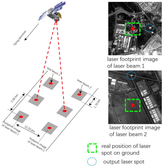
Figure 1.
Work schema for laser footprint cameras of GF-7 satellite.
2.2. Geometric Positioning Model of Laser Footprint Cameras
Rigorous imaging models of LFCs are based on the collinear condition Equation [25] and can be constructed by using the satellite orbital data during imaging, the attitude data measured by the star sensor, and the installation relation between the LFCs and the satellite body-fixed coordinate system without considering the influence of atmospheric refraction and other factors:
where represents the three-dimensional coordinates of the ground point in the WGS84 coordinate system; represents the origin position of the satellite body-fixed coordinate system in the WGS84 coordinate system; is the transformation matrix from the J2000 coordinate system to the WGS84 coordinate system; and represent the rotation matrix and position offset of the LFC relative to the satellite body-fixed coordinate system, respectively; is the coordinate of the image point corresponding to the ground point in the image coordinate system; is the coordinate of the principal point of the photograph in the image coordinate system; is the camera constant; and is the scale coefficient.
The rigorous geometric positioning model is valid only under ideal conditions. However, in practice, the measurements performed using various instruments carried by satellites are not very accurate, and the initial key parameters may change, causing errors in the rigorous geometric positioning model [26]. Depending on the characteristics of the error sources, LFC geometric positioning errors can be divided into external and internal errors [23].
External errors mainly result from the changes in external orientation elements and include time measurement error, orbit measurement error, attitude measurement error, and instrument installation error. The time measurement error can be regarded as the error of the orbit and the attitude calculation in the geometric positioning process. The positioning error caused by the orbit measurement error is equivalent to the error itself and can be ignored when using a precision orbit. Because of the distance amplification effect, the satellite attitude measurement error causes a more significant positioning error and becomes the main source of calibration error, which can be reduced by post-processing precise attitude data. The instrument installation error includes the offset and rotation of various instruments relative to the satellite body-fixed coordinate system, among which the variation of the offset is very limited and can be neglected. However, the rotation is greatly affected by the distance amplification effect and must be eliminated to the greatest extent via on-orbit calibration.
The internal errors are caused by the distortion of the camera lens and the arrangement of the sensors in the focal plane. The LFCs on the GF-7 satellite use a nonmetric camera with large lens distortion, and the introduced error cannot be ignored. It is also necessary to eliminate the positioning error caused by lens distortion through on-orbit calibration.
3. Calibration Method
3.1. External Calibration
Among external errors, the orbital measurement error can achieve cm-level positioning accuracy through post-processed precise orbit determination [27]. When post-processed precise attitude data are used, the attitude measurement error fluctuates with time but is systematic in a short time [28,29]. Systematic errors occur because of the vibration during launch and the difference in the environmental conditions before and after entering the orbit. External calibration is mainly used to eliminate the systematic errors that occur during instrument installation.
A rotation matrix is introduced into the rigorous geometric imaging model Equation (1) of the LFC to compensate for the systematic error caused by instrument installation:
where is the compensation matrix of the system error, which is composed of three rotation angles, i.e., , , and , as follows,
a linearized error equation was constructed to solve these three rotation angles. Regarding the orbit, attitude, and other data as true values, Equation (2) can be written as the following equation:
where , .
On the left-hand side of Equation (4), is the direction of the real incident light determined by the ground point coordinates in the image space coordinate system; on the right-hand side of the equation, is the direction of the incident light determined by the focal sensor of the LFC in the image space coordinate system. According to the collinear condition, these two directions should be parallel in theory; however, because of various errors, there is a small systematic deviation between them, which causes the final geometric positioning error. The following formula was obtained by removing the unknown parameter from Equation (4):
where .
For a ground-control point (GCP), the error equation can be constructed by linearizing Equation (5) as follows:
where indicates the residuals for x and y coordinates; is the correction of the rotation angles; is the constant of the error equation, calculated according to the initial value; is the linearized coefficient matrix; and is the index of the GCP. By combining the error equations for all GCPs, we obtain the following overall error equation:
where ,, , in which is the total number of GCPs. The three corrections are solved via least square adjustment:
After calculating the compensation matrix and eliminating the external error, the geometric positioning of the LFC can be obtained using Equation (2). During external calibration, two equations can be obtained from one GCP. Therefore, in theory, the compensation matrix can be calculated using the two GCPs. However, more GCPs are recommended to ensure the robustness of the solution.
3.2. Internal Calibration
After external calibration, the global positioning error of the footprint image was eliminated, leaving the local positioning error in the image range. The internal calibration was based on the pointing angle model. For image point coordinates on the footprint image, the pointing angle in the image space coordinates of the LFCs can be expressed as follows:
where and are the pixels corresponding to the pointing angle; and are the coordinate values of the principal point of the image; is the camera constant.
Owing to internal errors, there is a certain deviation between the real and theoretical pointing angles corresponding to an image point. The theoretical pointing angle was used to build a rigorous geometry model, and the image was captured according to the real pointing angle. Internal calibration was used to make the theoretical pointing angle as close to the real pointing angle as possible. For this purpose, the general cubic polynomial, which has high orthogonality and low correlation, was used to fit the real pointing angle of the image point [19]:
where denote the internal calibration coefficients. The process of internal calibration involves solving 20 calibration parameters in Equation (10). The error equations of the internal calibration can be constructed using Equations (3), (9) and (10). These error equations constitute a linear system of equations that can be solved directly via least-squares adjustment.
3.3. On-Orbit Geometric Calibration Process
The on-orbit calibration of GF-7 LFC adopts an iterative method of external and internal calibration. The overall calibration process is illustrated in Figure 2.
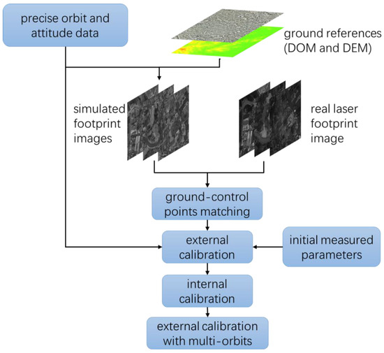
Figure 2.
Calibration flow for laser footprint cameras of GF-7 satellite.
In the internal calibration process, it is necessary to obtain a large number of uniformly distributed GCPs to more accurately calculate the internal calibration parameters. Many factors, such as small image size, weak image texture, and large differences in rotation and resolution, make it difficult to match GCPs from high-accuracy reference images (Digital Orthophoto Map, DOM). It is difficult to obtain a sufficient number of GCPs using only single-scene images. To solve this problem, we adopted the joint calibration of multi-scene footprint images in the calibration area. According to the exposure time of each laser footprint image, combined with the post-precision orbital and attitude data and various initial parameters, a rigorous geometric positioning model was used to simulate the footprint images [30]. Each pixel of the simulated footprint image was ray-traced onto the reference digital elevation model. The pixel value was then obtained via Gaussian filtering around the corresponding location in the reference DOM. Because the resolution is relatively low, the geometric accuracy loss during the simulation can be ignored. After the simulation, the GCPs were matched automatically combined with Harris features [31] and least-squares matching between the real laser footprint images and corresponding simulated footprint images. Least-squares matching can achieve subpixel precision and is robust for local distortion and radiative transformation because it makes full use of the local information for adjustment calculations [25,32].
When only a single measurement area is used for external calibration, random errors caused by satellite-specific conditions, such as instantaneous jitter of the satellite platform or temperature changes of the instrument are also systematic. As a result, the geometric positioning accuracy of the calibration results in the calibration area is very high, but the accuracy in other areas may be significantly degraded, resulting in unreliable calibration results. After the internal calibration was completed, we used multi-track ground reference data in different areas to perform external calibration for reducing the influence of random errors on calibration results.
4. On-Orbit Calibration Experiments
4.1. Internal Calibration Experiments
Experimental data were obtained in September 2020 in Huzhou, Zhejiang Province, China. The reference data included a highly accurate DOM and digital elevation model at a 1:2000 scale, which were acquired via aerial photography in 2018. Within the geographic range of the reference data, 10 and 11 scenes of footprint images were selected for LFC1 and LFC2, respectively (excluding footprint images with large clouds). The distribution of the data is shown in Figure 3. Using the initial parameters measured in the ground laboratory before the launch, combined with the precise attitude and orbital data and the exposure time of each footprint image, the footprint images were simulated using the rigorous geometric positioning model of the LFCs. The simulated images were then matched with the corresponding actual images to obtain 1066 and 991 high-precision GCPs for LFC1 and LFC2, respectively.
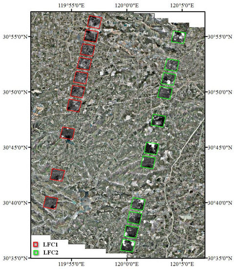
Figure 3.
Referencing digital orthophoto map and laser footprint images in calibration area.
First, an initial external calibration was implemented. The residuals of the GCPs in the calibration area are shown in Figure 4, and the residual statistics are listed in Table 2. The overall systematic error was eliminated, and the residuals were the internal errors caused by the distortion of the camera lens. The residuals were larger in the margin and smaller in the centre.
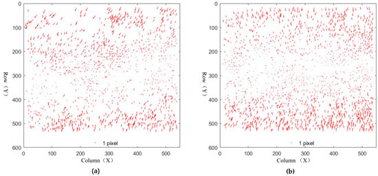
Figure 4.
Residuals after external calibration of laser footprint cameras (LFCs). (a) Residual after external calibration of LFC1. (b) Residuals after external calibration of LFC2.
Table 2.
Residuals after external calibration of laser footprint cameras (LFCs).
Following the initial external calibration, an internal calibration was conducted. The residuals of the GCPs after internal calibration are shown in Figure 5, and the residual statistics are listed in Table 3. The residuals after the internal calibration are significantly reduced compared to those after the initial external calibration, and their size and direction are random. The residual statistics show that the internal calibration accuracy of the two-beam LFCs is better than 0.7 pixels.
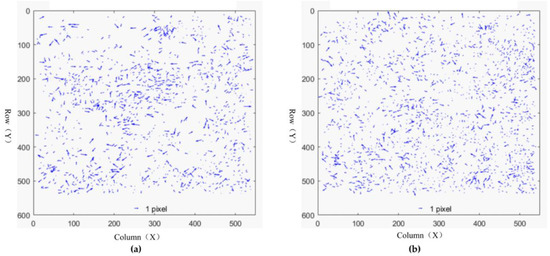
Figure 5.
Residuals after internal calibration of laser footprint cameras (LFCs). (a) Residuals after internal calibration of LFC1. (b) Residuals after internal calibration of LFC2.
Table 3.
Residual statistics after internal calibration of laser footprint cameras (LFCs).
Figure 6 shows the distorted internal surfaces of the LFCs. The internal error presents the characteristics of a large error near the edge of the image and a small error near the centre, and this feature is more obvious in the vertical direction (Y direction). The distortion of LFCs do not exhibit a normal radial distortion pattern because the field view ranges do not equal in the vertical and horizontal directions. In the vertical direction of the image, the field view varies from ±0.6~±0.8°, but ranges from −0.1~+0.1° in the horizontal direction. A larger radical view angle will cause greater distortion. Therefore, the LFCs had a wider range of distortion in the vertical direction.
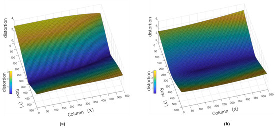
Figure 6.
Internal distortion of laser footprint cameras (LFCs). (a) Internal distortion of LFC1. (b) Internal distortion of LFC2.
Ground targets were used to validate the internal calibration accuracy during on-track calibration. On 9, 14, and 19 June 2020, the two-beam LFCs captured all four ground targets (Figure 7). The four target points on the footprint image were first used for external calibration to eliminate the external error, and the residuals of the target points after external calibration were used to evaluate the internal calibration accuracy. After external calibration, the average residuals of the four target points on the footprint images were close to zero (Table 4). The horizontal positioning accuracy of the four target points on each image was within 2.0 m, and the RMSE was approximately 1.0 m, which are equivalently better than 0.4 pixels. The accuracy validation results were better than those of the internal calibration residual (0.7 pixels), owing to the use of multiple images in the internal calibration process. Although the imaging time interval of each image was short, small attitude differences between different scenes resulted in larger residuals. The verification results showed that the internal calibration accuracy of the GF-7 two-beam LFCs was better than 0.7 pixels.
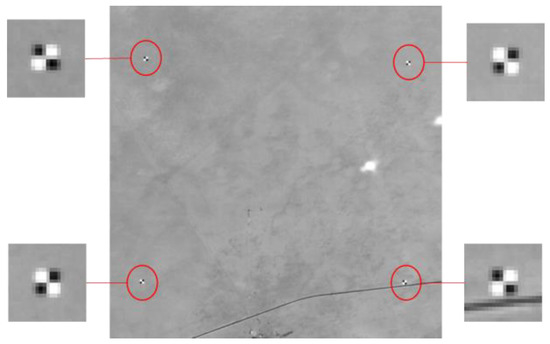
Figure 7.
Ground targets on footprint images.
Table 4.
Validation results for internal calibration of laser footprint cameras (LFCs).
4.2. External Calibration Experiments
To avoid unreliable calibrations resulting from the strong correlation between individual calibration areas and the specific state of the satellite over a short period of time, the data used were obtained from multiple tracks in different regions for collaborative external calibration to minimise the impact of random errors in satellite attitude on the final geometric positioning accuracy of the footprint image. Based on internal calibration, a refined external calibration process was performed by selecting the target points on footprint images during the laser on-orbit calibration and high-precision GCPs obtained from the reference data in Huzhou, Zhejiang Province, China. The calibration residuals are listed in Table 5.
Table 5.
External calibration residuals with multi-orbits.
In the footprint images of each scene, except for certain GCPs whose residuals are greater than 6.0 m, the RMSEs of external calibration residuals are less than 5.0 m. The RMSEs of the two-beam LFCs are 2.809 and 3.366 m, which are approximately one pixel. The footprint images involved in the calibration were acquired at different times and in different regions; however, they were relatively consistent, and the positioning deviation of all images was within two pixels.
5. Accuracy Validation of Laser Footprint Images
5.1. Validation with Ground Checkpoints
To fully evaluate the absolute geometric positioning accuracy of GF-7 LFCs after refined external calibration, a number of checkpoints were used. The validation adopted two tracks of GF-7 LFC data over Shaanxi Province (26 April and 1 May 2020). A total of 11 footprint images were selected, and three to four feature points were measured using GPS receivers as checkpoints on each footprint image. A total of 41 checkpoints were measured. The distribution of checkpoints and footprint images is shown in Figure 8.
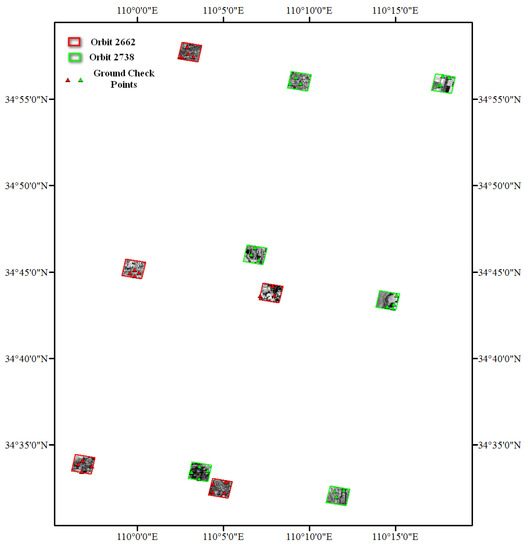
Figure 8.
Distribution of checkpoints and laser footprint images in validation area.
The accuracy of the checkpoints in the validation area is presented in Table 6. The positioning deviations of the footprint images are less than 3.2 m, that is, within one pixel. The horizontal errors of just a few checkpoints are above 7.0 m because the resolution of the footprint image is low, and the checkpoints are difficult to select. In general, the RMSEs of the checkpoints in the validation area are less than 5.0 m, and the accuracy is slightly lower than that in the calibration area. In addition, the positioning deviation of the two-beam LFCs in this area has obvious directionality, owing to a certain degree of systematic deviation after various satellite instruments have been started for a period of time.
Table 6.
Validation results for external calibration with multi-orbits.
5.2. Validation with High Accuracy Reference Images
High-accuracy reference images were used to evaluate the footprint images for a long period of up to a year. The reference images are orthophoto products (DOM) acquired by aerial photography with resolutions better than 0.5 m and positioning accuracy better than 1.0 m. The reference images are distributed in North Rhine-Westphalia in Germany [33], Shenyang, and Tianjin in China, which are far away from the calibration areas. Several homographic points were manually selected between the footprint images and reference images. The geolocation errors of the corresponding points were calculated, and the statistics are shown in Table 7. The data in Table 7 show that the positioning accuracy of footprint images reaches 6.0 m.
Table 7.
Validation results with high accuracy reference images.
6. Conclusions
The LFCs of the GF-7 satellite are important parts of the laser altimetry system, and laser footprint images are important references for laser footprint positioning. In this study, a rigorous geometric positioning model of the LFCs on the GF-7 satellite was constructed. Based on the characteristics of the laser footprint images, a joint calibration method of multiple images combined with image simulation, which eliminated the internal and external errors in the geometric positioning process of the GF-7 LFCs, was developed. The internal calibration accuracy was better than 0.7 pixels, and the RMSE of the footprint images’ absolute geometric positioning reached approximately 6.0 m after using precise post-processing orbital and attitude data. Our study has provided guidance for the production of laser altimetry data products with geolocated laser footprint images and strongly supported subsequent applications, especially for the combined stereo mapping of high-resolution images with laser altimetry data.
After on-orbit calibration, the most uncertain factor affecting the geometric positioning accuracy of the GF-7 footprint image was the precise attitude data. It is essential to explore the law of precise attitude data in different periods and regions to ensure the stability of the long-period geometric positioning accuracy of GF-7 footprint images in the future.
Author Contributions
Conceptualisation, X.T., J.C. and X.Z.; methodology, J.C. and G.L.; software, J.C. and G.L.; validation, L.H. and X.D.; formal analysis, J.C. and B.Z.; investigation, G.L. and B.Z.; data acquisition, L.H. and X.D.; writing—original draft preparation, J.C. and B.Z.; writing—review and editing, J.C. and B.Z.; visualisation, J.C. and B.Z.; supervision, X.T., G.L. and X.Z; project administration, X.T. and X.Z.; funding acquisition, X.T. and G.L. All authors have read and agreed to the published version of the manuscript.
Funding
This research was funded by the Special Fund for High-Resolution Earth Observation System Major Project (grant number: 42-Y30B04-9001-19/21).
Institutional Review Board Statement
Not applicable.
Informed Consent Statement
Not applicable.
Data Availability Statement
Not applicable.
Acknowledgments
We would like to thank Genghua Huang from Shanghai Institute of Technical Physics, Chinese Academy of Science for his kind information about the design and construction of the laser altimetry system of GF-7 satellite. We would also like to thank the anonymous reviewers for their insightful comments and valuable suggestions.
Conflicts of Interest
The authors declare no conflict of interest.
References
- Schutz, B.E.; Zwally, H.J.; Shuman, C.A.; Hancock, D.; Dimarzio, J. Overview of the ICESat mission. Geophys. Res. Lett. 2005, 32, 97–116. [Google Scholar] [CrossRef] [Green Version]
- Abshire, J.B.; Sun, X.; Riris, H.; Sirota, J.M.; Mcgarry, J.F.; Palm, S.; Yi, D.; Liiva, P. Geoscience laser altimeter system (GLAS) on the ICESat mission: On-orbit measurement performance. Geophys. Res. Lett. 2005, 32, L21S02. [Google Scholar] [CrossRef] [Green Version]
- Xinming, T.; Guoyuan, L.; Xiaoming, G.; Jiyi, C. The Rigorous Geometric Model of Satellite Laser Altimeter and Preliminarily Accuracy Validation. Acta Geod. Et Cartogr. 2016, 45, 1182–1191. (In Chinese) [Google Scholar]
- Renxiang, W. Chinese photogrammetry satellite without ground control points (2)—Technical thinking of 1:10,000 scale data-transferring photogrammetry satellite. Spacecr. Recov. Remote Sens. 2014, 35, 1–5. (In Chinese) [Google Scholar]
- Guoyuan, L.; Xinming, T.; Huabin, W.; Xiaoming, G. Research on the ZY-3 block adjustment supported by the GLAS laser altimetry data. In Proceedings of the 3rd China High Resolution Earth Observation Conference, Beijing: Major Special Management Office of High Resolution to Earth Observation System, Beijing, China, 1–2 December 2014; pp. 586–600. (In Chinese). [Google Scholar]
- Jin, W.; Yong, Z.; Zuxun, Z.; Xiao, L.; Pengjie, T.; Mengxiao, S. ICESat laser points assisted block adjustment for mapping satellite-1 stereo imagery. Acta Geod. Cartogr. Sin. 2018, 47, 359–369. (In Chinese) [Google Scholar]
- Ning, C.; Ping, Z.; Xia, W.; Xinming, T.; Guoyuan, L. Laser altimetry data-aided satellite geometry model refined processing. J. Remote 2019, 23, 291–302. (In Chinese) [Google Scholar]
- Guo, Z.; Kai, X.; Jia, P.; Hao, X.; Li, D. Integrating stereo images and laser altimeter data of the ZY3-02 satellite for improved earth topographic modeling. Remote Sens. 2019, 11, 2453–2477. [Google Scholar]
- Genghua, H.; Yuxing, D.; Jincai, W.; Rong, S.; Xin, W.; Ziqing, J. Design and implementation of key technology of GF-7 satellite laser altimeter subsystem. Spacecr. Eng. 2020, 29, 68–73. (In Chinese) [Google Scholar]
- Aiyan, G.; Jun, D.; Chenguang, Z.; Xinwei, Z. Design and on-orbit validation of GF-7 satellite laser altimeter. Spacecr. Eng. 2020, 29, 43–48. (In Chinese) [Google Scholar]
- Xinming, T.; Junfeng, X.; Ren, L.; Genghua, H.; Chenguang, Z.; Ying, Z.; Hongzhao, T.; Xianhui, D. Overview of the GF-7 laser altimeter system mission. Earth Space Sci. 2019, 7, e2019EA000777. [Google Scholar]
- Xinming, T.; Junfeng, X.; Fan, M.; Xianhui, D.; Xin, L.; Shaoning, L.; Song, L.; Genghua, H.; Xingke, F.; Ren, L. GF-7 dual-beam laser altimeter on-orbit geometric calibration and test verification. Acta Geod. Cartogr. Sin. 2021, 50, 384–395. (In Chinese) [Google Scholar]
- Jain, R.; Kasturi, R.; Schunck, B.G. Machine Vision; McGraw-Hill, Inc.: New York, NY, USA, 1995; ISBN 0-07-032018-7. [Google Scholar]
- Fraser, C. Digital camera self-calibration. ISPRS J. Photogramm. Remote Sens. 1997, 52, 149–159. [Google Scholar] [CrossRef]
- Yılmaztürk, F. Full-automatic self-calibration of color digital cameras using color targets. Opt. Express 2011, 19, 18164–18174. [Google Scholar] [CrossRef] [PubMed]
- Gruen, A.; Huang, T.S. Calibration and Orientation of Cameras in Computer Vision; Springer: Berlin/Heidelberg, Germany, 2001; ISBN 978-3-662-04567-1. [Google Scholar]
- Shao, X.; Eisa, M.M.; Chen, Z.; Dong, S.; He, X. Self-calibration single-lens 3d video extensometer for high-accuracy and real-time strain measurement. Opt. Express 2016, 24, 30124–30138. [Google Scholar] [CrossRef] [PubMed]
- Zhang, G.; Jiang, Y.; Li, D.; Huang, W.; Pan, H.; Tang, X.; Zhu, X. In-orbit geometric calibration and validation of ZY-3 linear array sensors. Photogramm. Rec. 2014, 29, 68–88. [Google Scholar] [CrossRef]
- Delevit, J.M.; Greslou, D.; Amberg, V.; Dechoz, C.; de Lussy, F.; Lebegue, L.; Latry, C.; Artigues, S.; Bernard, L. Attitude assessment using Pleiades-HR capabilities. Proc. Int. Arch. Photogramm. Remote Sens. Spat. Inf. Sci. 2012, 39, 525–530. [Google Scholar] [CrossRef] [Green Version]
- Radhadevi, P.V.; Müller, R.; d‘Angelo, P.; Reinartz, P. In-flight geometric calibration and orientation of ALOS/PRISM imagery with a generic sensor model. Photogram. Eng. Rem. Sens. 2011, 77, 531–538. [Google Scholar] [CrossRef]
- Cheng, Y.; Wang, M.; Jin, S.; He, L.; Tian, Y. New on-orbit geometric interior parameters self-calibration approach based on three-view stereoscopic images from high-resolution multi-TDI-CCD optical satellites. Opt. Express 2018, 26, 7475–7493. [Google Scholar] [CrossRef]
- Smiley, B.; Levine, J.; Chou, A. On-orbit calibration and validation of the skybox imaging constellation. In Proceedings of the ISPRS Technical Commission I Symposium, Sustaining Land Imaging: UAVs to Satellites, Denver, CO, USA, 17–20 November 2014. [Google Scholar]
- Wang, M.; Cheng, Y.; Chang, X.; Jin, S.; Zhu, Y. On-orbit geometric calibration and geometric quality assessment for the high-resolution geostationary optical satellite GaoFen4. ISPRS J. Photogramm. Remote Sens. 2017, 125, 63–77. [Google Scholar] [CrossRef]
- Xueli, C. Research on Key Technologies of Geometric Processing for High-Resolution Area-Array Camera of Stationary Orbit Satellite. Ph.D. Thesis, Wuhan University, Wuhan, China, 2015. (In Chinese). [Google Scholar]
- Jianqing, Z.; Li, P.; Shugen, W. Photogrammetry, 2nd ed; Wuhan University Press: Wuhan, China, 2009. (In Chinese) [Google Scholar]
- Xinming, T.; Jiyi, C.; Guoyuan, L.; Xiaoming, G.; Wenjun, Z. Error Analysis and Preliminary Pointing Angle Calibration of Laser Altimeter on Ziyuan-3 02 Satellite. Geomat. Inf. Sci. Wuhan Univ. 2018, 43, 1611–1619. (In Chinese) [Google Scholar]
- Chunmei, Z.; Xinming, T. Precise Orbit Determination for the ZY-3 Satellite Mission Using GPS Receiver. J. Astronaut. 2013, 34, 1202–1206. (In Chinese) [Google Scholar]
- Xinming, T.; Junfeng, X.; Xiao, W.; Wanshou, J. High-Precision Attitude Post-Processing and Initial Verification for the ZY-3 Satellite. Remote Sens. 2015, 7, 111–134. [Google Scholar]
- Xie, J.; Tang, X.; Mo, F.; Liu, Z. Domestic Stellar Image Post-processing Project Design and System Implementation for ZY-3 Satellite. Geomat. Inf. Sci. Wuhan Univ. 2017, 42, 434–440. (In Chinese) [Google Scholar]
- Murthy, K.; Chau, A.H.; Amin, M.B. An earth imaging camera simulation using wide-scale construction of reflectance surfaces. In Proceedings of the Sensors, Systems, and Next-Generation Satellites XVII, Dresden, Germany, 24 October 2013. [Google Scholar]
- Chen, J.; Zou, L.; Zhang, J.; Dou, L. The comparison and application of corner detection algorithms. J. Multimed. 2009, 4, 435–441. [Google Scholar] [CrossRef] [Green Version]
- Ackermann, F. High precision digital image correlation. In Proceedings of the 39th Photogrammetric Week, Stuttgart, Germany, 19–24 September 1984; pp. 231–243. [Google Scholar]
- OpenGeodata. NRW. Available online: https://www.opengeodata.nrw.de/produkte/geobasis/ (accessed on 16 August 2020).
Publisher’s Note: MDPI stays neutral with regard to jurisdictional claims in published maps and institutional affiliations. |
© 2022 by the authors. Licensee MDPI, Basel, Switzerland. This article is an open access article distributed under the terms and conditions of the Creative Commons Attribution (CC BY) license (https://creativecommons.org/licenses/by/4.0/).