Abstract
While outdoor navigation systems are already represented everywhere, the enclosed space is much less developed. The project Level 5 Indoor Navigation (L5IN) presents a new approach with mobile phone standard 5G as the orientation signal and without additional infrastructure for navigation in indoor environments. The aim of this project is to use the new available 5G technology to show how navigation systems, which have thus far only been available in the outdoor segment, can now be integrated into existing smartphone systems for indoor navigation. This paper gives an overview of the project and presents the different work packages leading to a holistic approach towards the development of an indoor navigation application for pedestrians. By using a specific app with open interfaces, it is planned to make navigation possible in all buildings modeled according to certain standards. The challenge involved is that, unlike outdoor maps, there is no map basis for buildings. For this reason, different approaches to map generation were examined. In a building information model (BIM), all information will be collected and made available via a database for positioning and visualization. The focus is furthermore on positioning, achieved through smartphone sensors and 5G, so that users can orientate themselves in buildings without having to connect to singular systems. It shall be shown that positioning with a standard deviation of 2–3 m and a confidence interval of 68 % is possible. Another advantage of 5G, the ability to send real-time data in higher data packages, will be used for data transmission. The basic idea of 5G-based indoor navigation will be enabled with radio cells of the providers, which will be set up on the HafenCity University campus. The complex university building will be used as a prototype environment.
1. Introduction
Navigation is the art and science of determining the position of a mobile vehicle, and guiding it to a specific destination [1], thereby answering the question of how to “get from point A to point B”. In large areas, at sea or in the air, outdoor navigation based on GNSS is standard today. The decisive advantage here is the open space with good signal reception, which thus ensures sufficient permeability.
Google Maps is one of the most popular projects benefiting from GNSS, meaning that it is therefore limited to outdoor services. However, the mobile Maps application directs people almost anywhere and anytime around the globe [2]. Navigation paths are not the same for all types of users; for instance, cars need different route to bicycles. Users may select the desired navigation type that they would like to be navigated by. When it comes to indoor navigation usage, specialized solutions are available to provide services only for limited buildings or users.
The enclosed space is much less developed, as it is often not possible to work with GNSS data. However, large building complexes and connected facilities, such as a campus with many buildings, also require navigation aids. Therefore, indoor navigation has become a central challenge in recent years [3]. Bluetooth or WLAN solutions are the most used today [4,5,6], but these methods of positioning usually require a client system, e.g., in the form of a software app on a smartphone, special devices, or at least a login to the WLAN system. These systems are therefore neither autonomous nor anonymous. There are also limitations regarding the availability of corresponding visual navigation material, such as missing map material. In contrast, the corresponding outdoor navigation maps are generated automatically, thanks to the long-time availability of GNSS positioning. Different mapping technologies like mobile mapping systems can provide and update the map information automatically and regularly around the world, because there is GNSS solutions as a reference for positioning.
Even a giant company like Apple has shown interest in using WLAN-based positioning techniques. However, as is discussed later, WLAN and similar approaches cannot be considered as extendable positioning techniques. Regarding the Apple Indoor program [7], preparing maps for indoor positioning purposes plays an important role. Users can define different layers of access for public usage, including the level, units, and opening. It is shown later that the BIM can provide even deeper information for use in indoor maps.
The project Level 5 Indoor Navigation (L5IN) represents a new approach to pedestrian indoor navigation based on novel technologies. The project consistently relies on mobile communications as the orientation signal. Here, the special performance of the future mobile communication standard 5G plays the central role in enabling technology. The aim of this project is to use the new available 5G technology to show how navigation systems, which have thus far only been available in the outdoor segment, can now be integrated into existing smartphone systems for indoor navigation. This is accompanied by the further development of positioning methods for indoor localization with a hybrid fusion of smartphone sensors and available information from 5G networks. In addition to a wide range of application possibilities, this will also enable simplified use that does not require specific integration into singular systems. Additional hardware technologies such as WiFi, which entail high maintenance and implementation costs, were avoided for navigation in the converted space and, furthermore, a generic offer was created, which allows a navigation ecology beyond a model use case. Indoor navigation will be enabled through the use of a specific app with open interfaces in all buildings that had been modeled accordingly.
2. L5IN Project Overview
As a pilot project, indoor navigation based on 5G New Radio (5G NR) mobile network is being developed and tested in a public building. For the research project the interesting components of the work with the new standard are the improvement of the positioning protocols that were initially implemented in the 4G Long Term Evolution-Advanced standard (4G LTE-A) and were further developed for 5G NR with improved positioning protocols for an increased accuracy in positioning [8,9]. In addition, the project will focus on the usage of the enhanced mobile broadband user profile (eMBB) with the possibility to send real-time data and larger data files, because of the increased available data rates for up- and downlink [10]. Furthermore, software solutions will be developed to facilitate the creation and integration of navigation maps. The building data will be collected using building information modelling and used for positioning as well as a basis for visualization. The complex building of the HafenCity University Hamburg will be used as a demonstration room.
The basic idea of 5G-based indoor navigation will be implemented with the existing radio cells of the providers (or their used standard technologies). It is expected that the complete coverage of building with the campus network’s radio signal will suffer from the existing building structure and therefore have an impact on the accuracy of the position estimation. Against this background, a technology partnership was planned within the framework of this project, in which an improvement in radio technology is to be achieved that will lead to a significantly higher quality of navigation (X < 2 m). However, the navigation architecture is designed for pedestrians who can still orient themselves visually even with 2 m accuracy.
In the following section, we present the included work packages of the project and the method in which we tried to achieve the goals for indoor positioning and navigation.
2.1. Generation of Building Plans and Models
A fast, safe, and reliable navigation is only possible if detailed knowledge about a location is available. While many official, commercial, and open source geodata are available worldwide for outdoor applications, hardly any plans are available for buildings or are not accessible to the user. Consequently, an effective process is required for the effective and efficient generation of building plans and models for indoor navigation applications.
In [11], the authors presented a method for creating indoor maps from rescue plans. For this aim, the user takes pictures of the rescue plans, which are then processed with the help of a suitable image editing pipeline. The result is a rough floor plan, which consists of polygonal room outlines and identified staircases, if possible. The authors of [12] integrated this approach into their investigation for deriving routing graphs from building plans. A photograph of the escape and rescue plan is first corrected by projective rectification. Then, all color elements are erased from the image to remove the supplementary routing symbols. Thresholds are used to generate a binary image that can then be used to calculate edges. However, this approach is not yet fully automatic, as some remnants of symbols and gaps in walls or black pixels require a final manual correction of the generated results.
In order to provide suitable map material for indoor navigation application in the L5IN project, different available 2D and 3D geodata for public buildings need to be evaluated regarding their usability. In doing so, which possibilities exist for further processing of building plans and how complex these are will need to be investigated. For this purpose, the data are to be digitized, generalized, and blended automatically. Existing approaches are to be implemented and an optimal strategy developed. In this way, it should be possible to create a map data set as easily and quickly as possible, e.g., with escape and rescue plans, which exist almost everywhere in public buildings such as universities, shopping centers, and airports.
For new buildings, there are often already digitized building plans available, e.g., in dwg format. These can be processed into a BIM. One advantage is the fast handling, because additional information such as room number and type are often included and can be used. In the absence of plans or if the available geodata is insufficient, current measurement systems and procedures for a complete 3D survey of the essential features of a building are to be investigated. In order to evaluate them with regard to the requirements of the overall project, the following criteria must be observed: required resolution of the 2D/3D geodata, target accuracy, object characteristics (measurability of building parts), building dimensions, coordinate system (geo-referencing to the exterior). Based on the most economical overall solution, comprising measurement technology, measurement procedures, and fusion algorithms, the survey of the building of HafenCity University is to be implemented together with a BIM. Furthermore, models for navigation and visualization are to be derived from the survey data. This modeling of geometric models is to be automated as much as possible using data-based and stochastic algorithms, so that efficient scalability of the usable data is possible. In the next step, an enrichment with case-specific semantic information can lead to a BIM that can be used as a data source for indoor navigation.
2.2. Building Information Model
A BIM is used to support indoor navigation within L5IN project. The underlying approaches for the decision are described in the following. The advantage of working with BIMs is that different information about a building can be collected centrally within a data set. Information that otherwise comes from different sources (such as drawings, tables, presentations, and charts) can be bundled within a BIM. The fact that working with BIMs allows the use of a combination of semantic, geometric, and topological attributes is one reason for their growing usage in different cases [13,14].
Wherever possible, open data formats will be used in the L5IN project. The data format of the Industry Foundation Classes (IFC) from buildingSmart is one of the most widely used formats. Even if not all software manufacturers have implemented the current IFC 4 schema yet, it will be used in the project due to its actuality. Further information on the schema can be found in the documentation provided by buildingSmart [15]. The use of the IFC schema can also be found in various other projects for purposes of geometric representation, routing, etc. [13,16,17]. Note that the IFC STEP Physical File (IFC SPF) is not the only way to export BIMs from the native data formats of the modeling software. Besides the IFC SPF, there are also export options in the form of data tree structures such as JSON or XML [18]. In contrast to the IFC SPF, these offer a more user-friendly and human-readable form and are therefore used in various other projects [13,14] and will be in the L5IN project as well.
The BIM will be stored in a database for use in the L5IN project; therefore, it should be considered that BIMs, in their function as a single source of information, have several features that are not required for indoor positioning and navigation. Like other projects, the model will be decomposed into geometrical, semantic, and topological dimensions, whereby the range of features will be reduced accordingly before they can be mapped in a suitable database framework [13,19,20,21,22].
The use of BIMs in the context of the presented project is shown below for subarea navigation and positioning separately. In the area of navigation, the project team expects added value from the use of a BIM for map creation and display, as well as for the generation of routing graphs. Due to the already mentioned role of the model as a single source of information for relevant building information, it makes sense to generate the required maps directly from the model. A distinction must be made whether the modeled 3D geometries of the BIM should be used directly for a navigation application [17] or if they should be abstracted from the 3D geometries and used as a 2D map [13,19].
The existing geometry of the models are the basis for creating 2D maps. It will be investigated how a corresponding approach can be made using the data format IFC JSON, which is not yet officially published. Current algorithms for the conversion of IFC SPF into IFC JSON [23] are available from members of the technical room [24] of buildingSmart. This schema will be used to generate map data with the necessary details and information. Here, the model-based approach comes into play, so that both the semantic information (e.g., the occupancy, type of use, and accessibility of rooms) [19] and the topological information (e.g., door belongs to wall and wall is connected to room) [16] are used.
For positioning tasks, the project is currently looking at various approaches that are intended to support the determination of the user’s position, such as the provision of material information for the evaluation of the received signal strength, the provision of object information within the scope of map matching, and the modeling of landmarks to support positioning algorithms. To support the determination of the position based on the received 5G signals, information about the material properties of the surrounding components can be provided to the algorithm. The received signal should be better evaluated with regard to the change when hitting a building element (e.g., reinforced concrete wall and facade elements with coated glass surfaces).
With an eye to the transfer of information for map matching, relevant features can be added to the modeled building elements in order to use them accordingly (e.g., a wall represents an obstacle that is not passable or particles are located in rooms/zones that the user profile is not allowed/able to enter) [22,25]. To support the problem of orientation drift, it will be investigated to what extent the modeling and use of landmarks in BIMs should be considered. Landmarks can be extended as additional features with existing objects such as stairs, elevators, and doors with information about a change of direction or a change in altitude. Additional objects might have to be modeled to provide information about changes of direction in corridors or the change in altitude by using stairs or the elevator. It will be investigated whether the positioning algorithm can make a decision based on patterns of movement with respect to the path followed and how efficient the approach is [16,26].
2.3. Position Estimation
Micro-electro-mechanical systems (MEMS) are found in every smartphone. Reliable indoor positioning based on MEMS has been one of the goals of researchers in recent years. Among all of the available sensors in smartphones, inertial measurement units (IMUs) are those sensors that can be used at any time. Therefore, many positioning techniques rely on them as key sensors. Focusing only on the sensor-based methods with special attention on smartphones, it seems to provide a promising solution for people’s everyday lives. However, positioning techniques are still mostly limited to sensor drifts, placements, and defined labeled data. Therefore, wide ranges of different sensor technologies have been used to overcome the challenges in developing an indoor positioning system. Generally, inertial sensors can be used to provide information about the orientation and position of any object that they are attached to.
In 2010, smartphones with gyroscope sensors (such as the iPhone 4 [27]) were used for the first time after decades of studying the methods of the strapdown inertial navigation system (INS) [28]. Researchers were able to determine the 3D position, velocity, and attitude of sensors by integrating the raw data from the accelerometer and gyroscope. However, MEMS sensors are different from the expensive, heavy, and high precision IMUs used in ships, aircrafts, etc. Besides, in contrast to the traditional INS, mobile devices can be located in many different places, even without a unique pose in relation to the navigation body. Different scenarios of indoor positioning, such as on-shoe mounted and handheld techniques, began taking shape at this point in time.
The basis of pedestrian dead reckoning (PDR) is a combination of a pedometer, a known or estimated stride length, and orientation. The activity detection methods for indoor localization purposes, such as in [29], and PDR methods have started to mature, hoping to address the problems with INS. Due to the popularity of smartphones, the previous experiences in both the INS and the PDR methods remained in the center of attention. Although there were different step counting algorithms in different time domains, frequency domains, and clustering moods, evaluation and comparison helped to clarify windowed peak detection as the optimal choice [30] for the L5IN project, as it was shown to be work well in one of the most popular PDR benchmarks [31].
End-to-end systems are more complete systems that use different sensor fusion approaches, as well as external supports such as maps and absolute positioning techniques. They became even more interesting when passing doors and not walls, combined with topological approaches using particle filtering [32]. Due to the BIM generation process, geo-features and landmarks shape indoor positioning algorithms. For a robust real-time positioning solution, the challenges and open questions must be defined.
The first challenge in research regarding pose tracking is how to determine the initial pose (position and orientation) of the device. This seems to be a very important problem, because if it is possible to calculate the initial position, then it should also be possible to determine the next points. However, in order to provide a high-quality position, absolute methods using WLAN, Bluetooth, or UWB are among those individual solutions that either push users to register into the desired network or create more sensitivity regarding small environmental or anchor changes, as can be seen in fingerprinting approaches [31,32]. GPS initialization [33] is an accepted standard initialization method, but it obviously results in a strong limit for starting points. Manual user input is the only remaining way to start a navigation journey, maybe by using a QR code as another specialized solution [34]. While the real-time initial position needs to be solved by an absolute positioning technique, the initial orientation can be calculated differently for the pitch, roll and yaw. The pitch and roll are reliably calculatable based on the gravity estimation from accelerometer measurement [35]. However, a calibrated geomagnetic sensor value needs to be followed by a local magnetic map. Such a radio map or a magnetic distortion map relies heavily on a labelled dataset [36].
The next challenge addresses the different approaches of sensor tracking and pedestrian positioning. Research on orientation tracking in the context of indoor positioning tries to assess the heading of the device rather than the heading of the pedestrian. They therefore assume that the position of the mobile device is fixed and known or they neglect the misalignment between the smartphone heading and the user’s walking direction as an open problem [37]. However, there have been some attempts to calculate the heading independent of orientation, based on acceleration values and the principal component analysis (PCA) calculation [38] or similar approaches, such as frequency domain analysis, but there is potential for improvement to achieve the desired accuracy [39].
To overcome the abovementioned challenges, map support is not enough. Therefore, 5G positioning, which is an infrastructure-based solution and provides absolute position information, will be used for the L5IN project. The potential of 5G technology is seen as the base requirement. Dense 5G networks with a range of a few meters to tens of metres are envisaged. For instance, one can assume several access nodes per room in indoor enviroments and one access node on each lamp in outdoor areas [40]. In view of the popularity of smartphones for positioning, 5G-based methods are a perfect complement. It has been shown that an accuracy of 1 m and better is achieved in 70% of cases when different 5G positioning techniques are used [40].
Proximity, time of arrival (ToA), and direction of arrival (DoA), in combination with Kalman filtering, are common in the 5G positioning domain. In the proximity method, the position of the mobile terminal is calculated relative to the antenna node positions, for which the cell ID (CID) or the received signal strength can be used. For the ToA method, the propagation delay from a mobile terminal to an antenna node is measured. The distance is the propagation delay multiplied by the propagation speed of the signal (speed of light). The position of a mobile terminal can then be calculated using trilateration from the distances to several antenna nodes. For the DoA, the direction of the signal propagation from a mobile terminal to a referenced antenna node is measured using antenna arrays. To determine the angle, the difference of the time of arrival (TDoA) at each element of the antenna array is measured. These methods will be discussed and developed in future works.
In summary, sensor-based positioning methods need to overcome the problem of inertial sensor drift with additional support, such as maps and accurate absolute positions, to keep error accumulation at bay. Regarding the process of the L5IN project, 5G constraints can not only determine the initial position and orientation of the device, but can also provide solutions about the misalignment between the user and the device. Step detection and heading estimation methods can be accurately calibrated using 5G signals. The 5G runtime data and their related methods can be used in order to reach the required accuracy and frequency in a positioning task.
2.4. Modeling and Digitalization
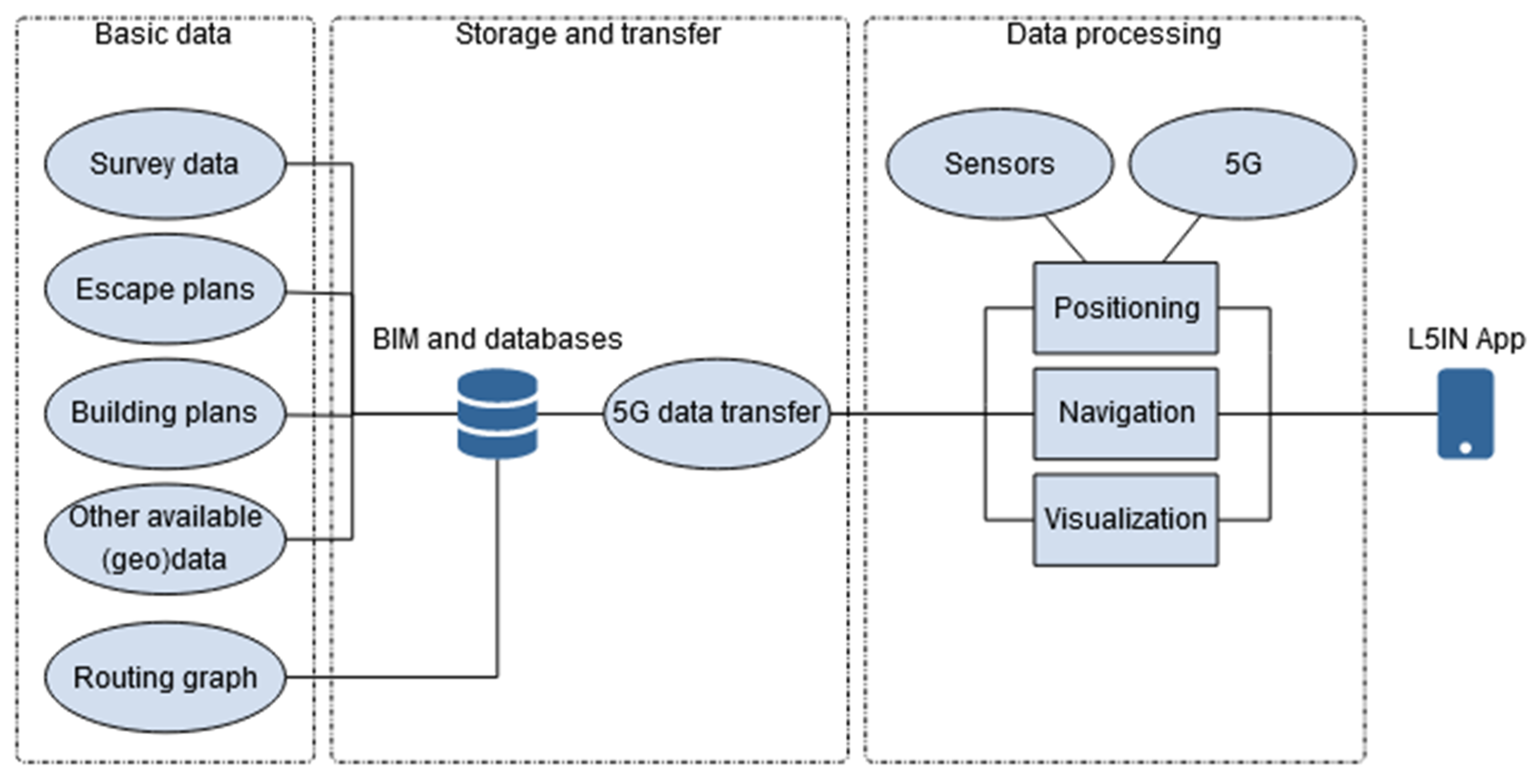
Based on the available data and the selected methods, the following structure was chosen for the navigation application (Figure 1). The data basis of indoor navigation serves, on the one hand, to create a map data set. These data can be existing building plans, building plans derived from escape and rescue plans, or other geodata. Apart from geometry, topological and semantic information also play a role. If no data are available for a building, it will be surveyed. Models were derived from these survey data, and all these data were integrated into a BIM. On the other hand, a routing graph for route calculation can form the basis as well. If necessary, this routing graph can be derived from building plans or directly from the BIM. In order to transfer the information about the locations to the navigation system, the data were stored in a database and an effective transfer format via the 5G mobile phone network to the end devices was developed. These data were used together with smartphone sensors and 5G signals for position estimation, as well as for navigation and visualization in the app.
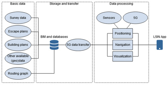
Figure 1.
Components and structure of the indoor navigation application.
In the area of digitization of the L5IN project, a first prototype for a navigation application is to be developed that can demonstrate the functionality and performance. In the first phase, a first 2D navigation model was developed with the existing data and information, containing the basic functionalities (location-to-location navigation, real-time updates, etc.). The essential basis of this prototype was the available planning fundamentals (construction plans, escape plans, etc.). For a later extension by 3D navigation, 3D models of the environment were developed with the help of a game engine based on the images. Corresponding navigation functionalities were implemented. At the end of the L5IN project, it is planned that all available software tools and class libraries will be provided. For this purpose, a corresponding application documentation is to be developed, which will also allow third parties to use it.
3. Implementation
In this section, an attempt was made to provide a current state of the project in order to show the methods implemented in the L5IN project. The goal is not to provide technical implementation details, but to demonstrate the concepts and related discussions.
3.1. PDR Positioning Using 5G
The combination of an accelerometer and a gyroscope is of particular interest for PDR. Often, these sensors are combined as three-axis sensors in a smartphone. The acceleration sensor registers the acceleration due to a gravity of 9.81 m/s2 on its three axes. This allows a tilt calculation, but step detection is also based on the registered accelerations. The three-axis gyroscope registers angular velocities. With appropriate time measurement, the relative angles of rotation in space can be determined by integration. However, these inertial sensors are subject to high measurement uncertainties, which affect the position estimation by means of PDR. In particular, the integration of the rotation rates of the gyroscope leads to drifts in the determination of direction and, therefore, also in the position.
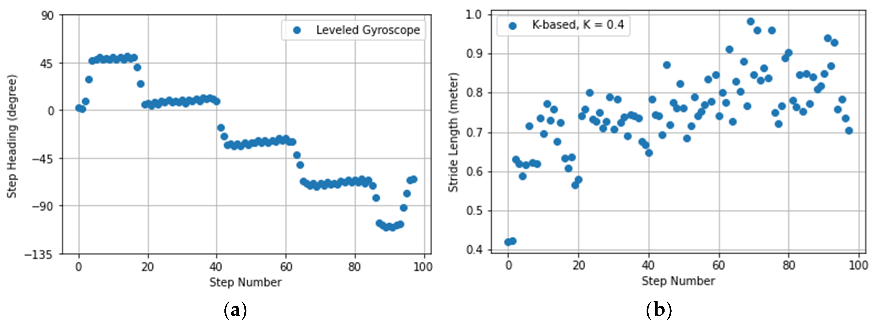
There are numerous implementation examples for the realization of PDR. The basis of PDR is a combination of a pedometer, estimated stride length, and orientation. Once a step is detected, the step length estimation should start. One can have different step length over the walking time due to environmental constraints, such as user speed and terrain conditions [31]. In this implementation, the step count and stride length are estimated by using acceleration data. The pedometer and the well-known k-based method, reproduced from [31] with K = 0.4, are used. The step orientation is calculated from the leveled gyroscope data by using the method in [32] (Figure 2).
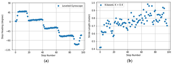
Figure 2.
Realization of pedestrian dead reckoning (PDR) elements in the reproduction of available benchmarks: (a) step heading calculation from leveled gyroscope values; (b) K-based stride length estimation.
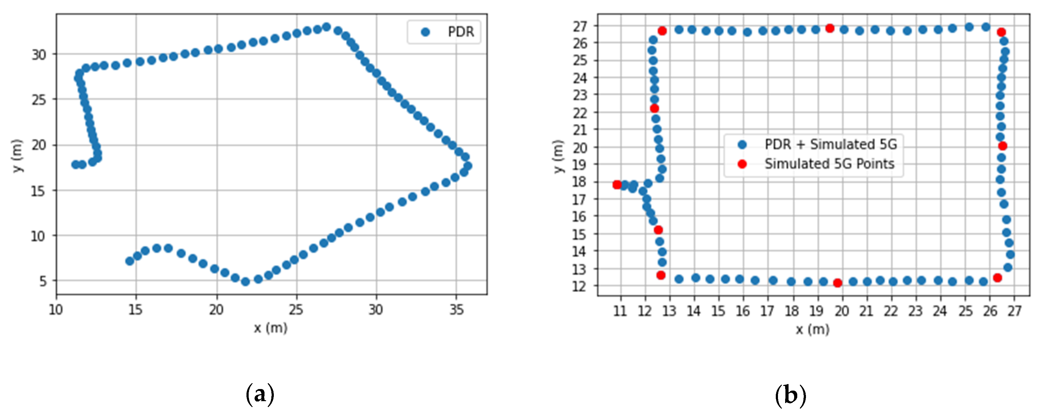
In PDR systems, it is necessary to solve the problem of inertial sensor drift. Additional constraints such as 5G reference points are needed to keep the error accumulation at a minimum. These constraints can not only determine the initial position and orientation of the device or the user, but can also provide information to keep the drift under control. The misalignment between user and the device should not be a problem any more, as the step detection and heading estimation methods can be accurately calibrated using 5G signals. In 3GPP Release 17, the aim is to generate horizontal positioning accuracy of at least one meter and better for commercial use cases, like 0.2 m for some use cases [41]. Based on that, some of the reference points are considered as simulated 5G points. Within a post-processing try, the PDR points can be projected onto the 5G reference points based on the ratio of the distance and azimuth difference between the PDR and the 5G points. Such a projection needs to wait for a 5G signal, additional to the start point, to calculate the azimuth difference and correct the heading. The simulation below was partially inspired by using the reference coordinate and corresponding time discovered by a video analysis to see the very first performance of such an idea. The results present a promising output using the 5G test network (Figure 3).
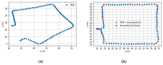
Figure 3.
5G simulation to correct the PDR coordinates: (a) implemented PDR using the abovementioned elements; (b) corrected PDR using the simulated 5G points.
3.2. 5G Campus Network Infrastructure
For the implementation in the L5IN project, a 5G non-standalone (5G NSA) campus network and an additional experimental system will be realized at HafenCity University Hamburg. Applications from the field of indoor navigation will be tested there and will serve research purposes.
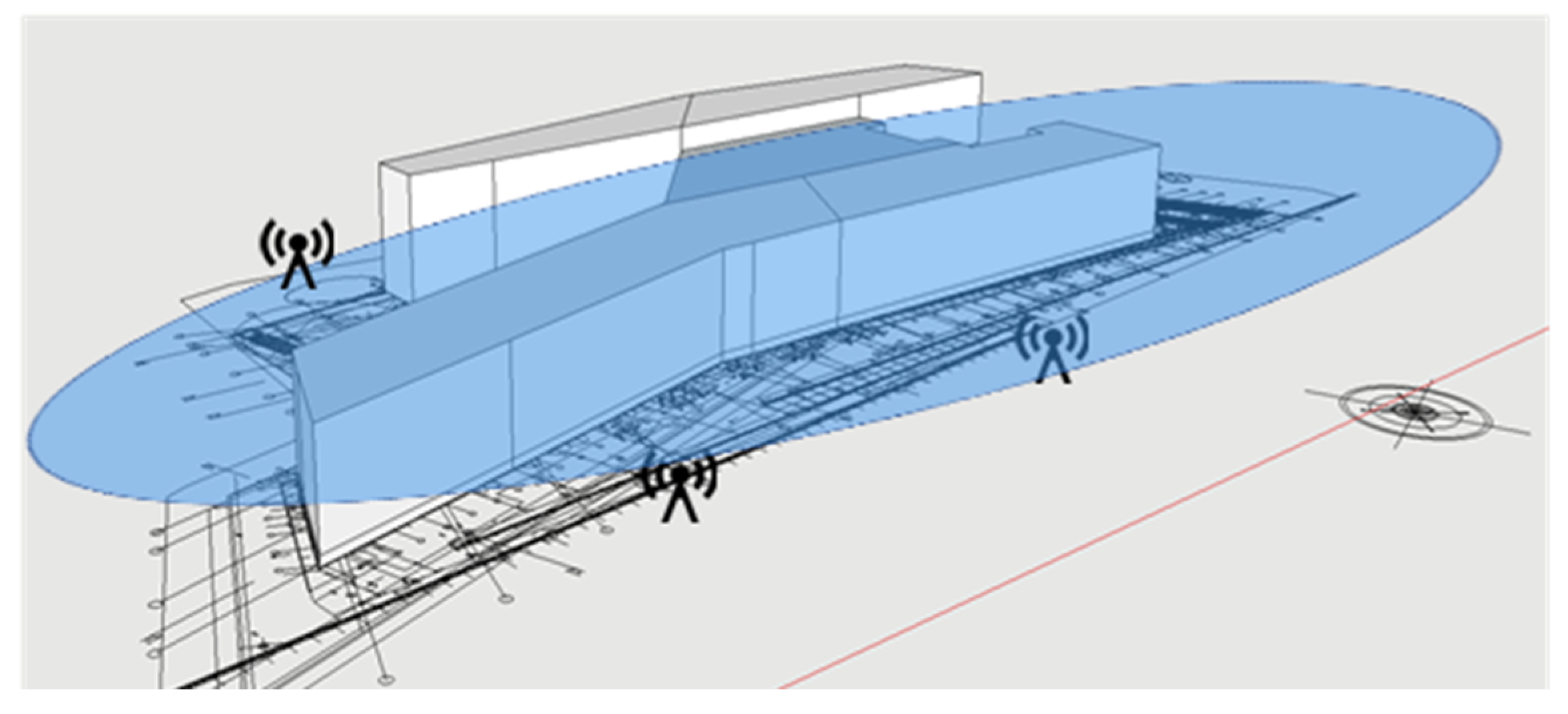
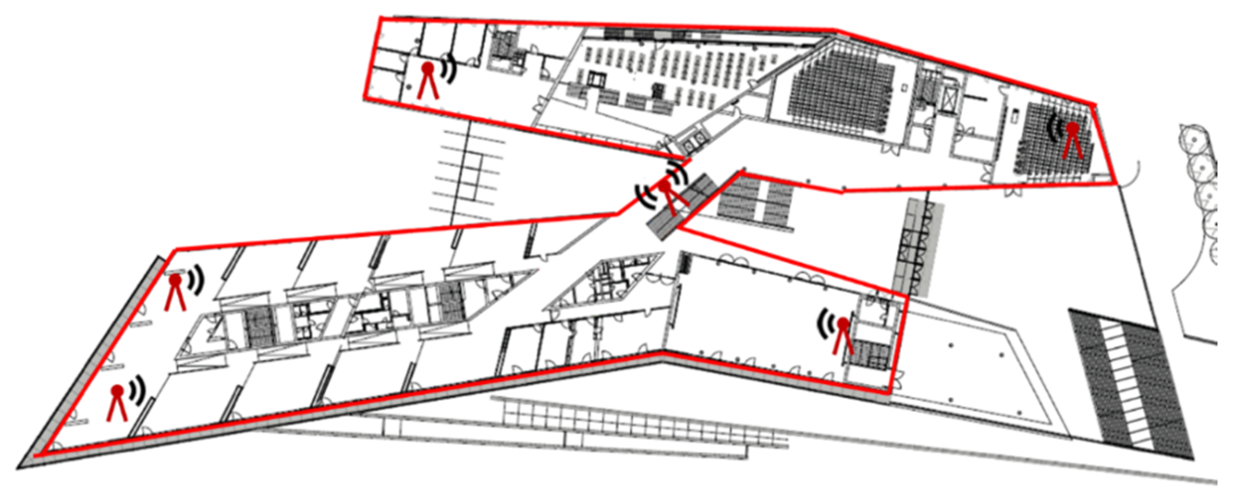
The 5G NSA network will comprise an outdoor campus network (Figure 4). Since outdoor antennas cannot guarantee coverage for every room, additional antennas will be set up indoors to create an additional indoor network (Figure 5). In this way, a greater area can be covered and the influence of the varying proportions of reinforced concrete components and lightweight walls on the quality of navigation in the interior can be investigated. To investigate the different characteristics and setups, different environments will be systematically tested. While one test floor will be characterized by large lecture halls and thin walls, the second test floor will be characterized by many small rooms and thick walls.
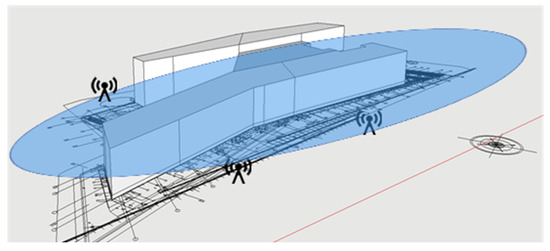
Figure 4.
Concept drawing for the outdoor antenna to provide a 5G non-standalone network.
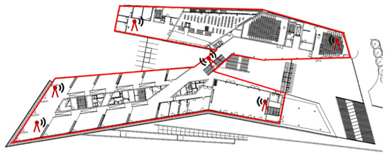
Figure 5.
Concept drawing for an additional indoor antenna to evaluate the need of indoor units in different indoor environments.
This network will use the private frequencies in band B43/N78 (3.7–3.8 GHz) with a 4G LTE anchor band. For the navigation of persons, sufficient accuracy is required for the positioning. The network data will be transmitted in real time, e.g., to change the navigation path, and the user behavior shall be analyzed.
3.3. Realization of BIM Using the Available Sources
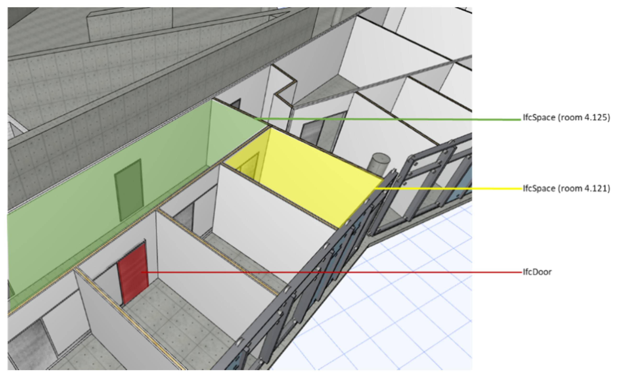
Figure 6 shows the current design status of the test environment. Only the components relevant for the use of case navigation are modeled. On the test floor, these are mainly objects of the object classes from the IFC data schema like IfcWall, IfcSlab, IfcWindow, IfcDoor, and IfcSpace classes. Figure 7 shows a section of the model with the corresponding objects. Each of the components has properties related to its material, its geometry, and its position in the structure, according to the IFC schema.

Figure 6.
Model of the prototype environment.
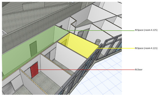
Figure 7.
Extract of the prototype environment showing the objects IfcSpace and IfcDoor.
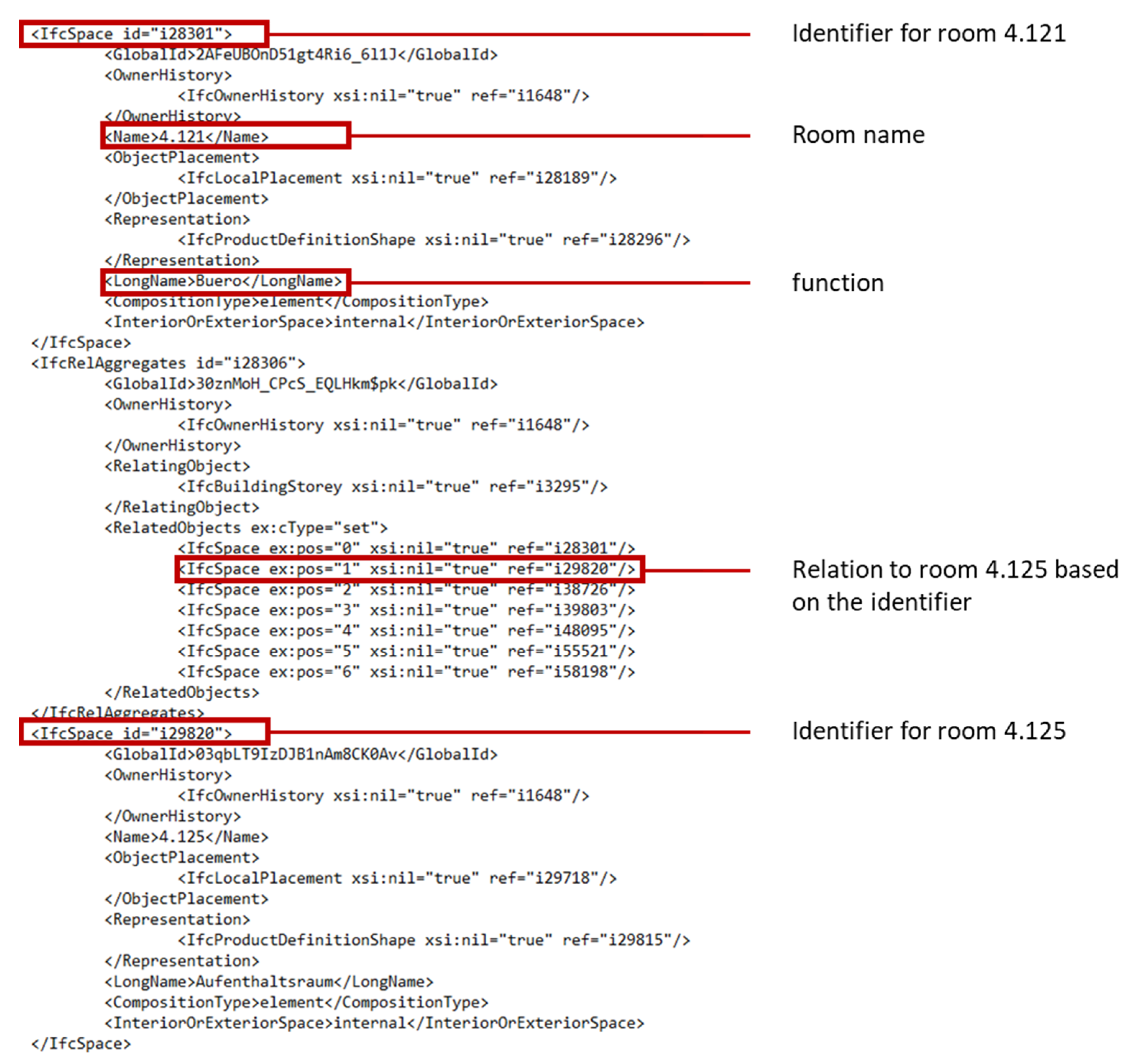
An excerpt from the IFC XML export of room 4.121 shows the mapping of topological information in the data schema, which is to be used, for example, for the generation of a routing graph (Figure 8). The room is shown here with information about its name and its use, which can be passed on to the corresponding nodes of the routing graph in further processes. The connection of the room to its surrounding objects is also shown. The topological information will also be used to enable automated generation and updating of the graph. In addition, the standardized IFC schema offers further possibilities to extend the individual rooms with appropriate information, such as accessibility in case of restricted areas, or regarding issues such as accessibility. The use of doors as a source of information will also be considered, as they can also make statements about the connected rooms due to their connecting function and are easier to handle in their geometry and location.
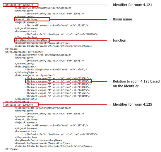
Figure 8.
Extract of the XML schema showing the relationship between IfcSpaces.
The challenges in working with BIMs include limiting the models to the necessary amount of information. In the course of model creation or the transfer of models from the planning process, the BIM has been enriched with a large amount of semantic information that is not required for the present case. For the basic application of indoor navigation, an information delivery manual has to be developed. Based on this manual, a model view definition for the export of a relevant subset of the model can be generated. Otherwise, a further conceivable way would be to filter only the relevant parts of the schema using an appropriate algorithm. Another challenge is the use of the geometric representation. As mentioned in the previous chapter, IFC SPF offers a variety of possibilities for the representation of geometric shapes. Since the navigation should be as simple as possible, it has to be worked out in the near future how the geometry can be converted and used in the JSON format.
4. Conclusions
An overview of the research of the L5IN project was given herein, describing the individual work packages and discussing the relationships between them. The aim of the L5IN project is to develop an autonomous application for indoor navigation. The workflow starts with a survey of the building and the processing of existing building plans. The geometrical, topological, and semantic data are merged into a BIM. Using this map as a basis, as well as 5G technology and smartphone sensors, positioning is carried out. The map is also used for visualization in a smartphone app. All these data are stored in a database and transmitted via the 5G network. The 5G network will be implemented in a campus solution on the premises of HafenCity University Hamburg as a prototype environment. With this holistic solution approach, it shall be shown that based on 5G technology, pedestrian indoor navigation with a standard deviation of 2–3 m and a confidence interval of 68% is possible.
5G makes indoor positioning possible anywhere and at any time, and it also plays an important role for any other positioning task. 5G positioning methods in combination with IMU sand GNSS solutions can improve the connectivity between indoor and outdoor environments. It is considered to be an infrastructure-based system, because 5G will be available to the vast majority of the population—as is planned for 2027 in the U.K., for example—while at the same time offering the possibility of providing 95% of the population with gigabit-capable networks by 2025 [41]. This amount of popularity and dependency between smartphones and 5G signal will solve the challenges that exist in typical infrastructure-based systems.
Smartphone positioning is the result of sensor fusion, 5G network signal, and plan information. Each of these elements can work more accurately using a BIM. In sensor fusion, a geomagnetic field map can be used to evaluate the 5G signal quality based on material properties. Moreover, 5G and BIM work in both data transformation and visualization tasks to enable standardization of indoor navigation. Therefore, real-time 3D navigation will be the next result of combining BIM and 5G.
Positioning is envisioned as an important element of 5G mobile networks. However, infrastructure-based methods are detrimentally affected by various factors, such as multi-path propagation and non-line-of-sight propagation (NLOS) reception. To deal with the negative influences, environmental conditions modeled in the BIM can be adopted. The BIM uses available sources such as building plans, images, and point clouds. Different data acquisition techniques will be discussed in future works. In this way, 5G positioning methods will be tested and developed within the 5G campus network. Meanwhile, positioning is supported by sensor-based and data-driven approaches, i.e., a realistic database can be established within the L5IN project.
A mobile application will be developed for both the IOS and Android platforms with an open-source license, offering a standardized form of indoor navigation. The application will guide the user with different options, such as using stairs or escalators. Both 2D and 3D visualization will be available to support users to navigate themselves using the L5IN app. Ultimately, a reliable prototype will be presented in order to take the field of indoor positioning one step further.
Author Contributions
Conceptualization, C.S., H.S. (Hossein Shoushtari), N.H. and H.S. (Harald Sternberg); methodology, C.S., H.S. (Hossein Shoushtari) and N.H.; formal analysis, C.S., H.S. (Hossein Shoushtari) and N.H; investigation, C.S., H.S. (Hossein Shoushtari) and N.H.; data curation, C.S., H.S. (Hossein Shoushtari) and N.H.; writing—original draft preparation, C.S., H.S. (Hossein Shoushtari) and N.H; writing—review and editing, C.S., H.S. (Hossein Shoushtari) and N.H.; visualization, C.S., H.S. (Hossein Shoushtari) and N.H.; supervision, H.S. (Harald Sternberg); project administration, H.S. (Harald Sternberg); funding acquisition, H.S. (Harald Sternberg) All authors have read and agreed to the published version of the manuscript.
Funding
This research and the L5IN project was funded by the Federal Ministry of Transport and Digital Infrastructure (BMVI), grant number VB5GFHAMB.
Data Availability Statement
No new data were created or analyzed in this study. Data sharing is not applicable to this article.
Conflicts of Interest
The authors declare no conflict of interest. The sponsors had no role in the design, execution, interpretation, or writing of the study.
References
- Navigation|National Geographic Society. Available online: https://www.nationalgeographic.org/encyclopedia/navigation/ (accessed on 5 November 2020).
- Google Maps’ Biggest Moments Over the Past 15 Years. Available online: https://blog.google/products/maps/look-back-15-years-mapping-world/ (accessed on 5 November 2020).
- Retscher, G. Indoor Navigation. In Encyclopedia of Geodesy; Springer International Publishing: Berlin/Heidelberg, Germany, 2016; pp. 1–7. [Google Scholar]
- Indoor Navigation—Mit WLAN Oder Bluetooth Beacons. Available online: https://www.infsoft.com/de/loesungen/anwendungen/indoor-navigation (accessed on 5 November 2020).
- Indoor Navigation Von Favendo|BLE Echtzeit-Lokalisierung. Available online: https://www.favendo.com/de/indoor-navigation (accessed on 5 November 2020).
- MapsIndoors—Indoor Navigation with Google Maps—MapsPeople. Available online: https://www.mapspeople.com/mapsindoors/ (accessed on 5 November 2020).
- Introducing the Indoor Maps Program—WWDC 2019—Videos—Apple Developer. Available online: https://developer.apple.com/videos/play/wwdc2019/245/ (accessed on 5 November 2020).
- 3rd Generation Partnership Project. Technical Specification Group Services and System Aspects—Release 14 Description (TR 21.914). 2018. Available online: https://www.3gpp.org/release-14 (accessed on 8 February 2021).
- 3rd Generation Partnership Project. Technical Specification Group Services and System Aspects; Service Requirements for the 5G System. 2020. Available online: https://www.3gpp.org/release-16 (accessed on 8 February 2021).
- 3rd Generation Partnership Project. Technical Specification Group Services and System Aspects—Release 15 Description (TR 21.915). 2019. Available online: https://www.3gpp.org/release-15 (accessed on 8 February 2021).
- Peter, M.; Fritsch, D.; Schäfer, B.; Kleusberg, A.; Bitsch Link, J.A.; Wehrle, K. Versatile Geo-Referenced Maps for Indoor Navigation of Pedestrians. In Proceedings of the 2012 International Conference on Indoor Positioning and Indoor Navigation, IPIN, Sydney, Australia, 13–15 November 2012. [Google Scholar]
- Schmitt, S.; Zech, L.; Willemsen, T.; Sternberg, H.; Kyas, M. Conditional erosion to estimate routing graph out of floor plans. In Proceedings of the 2016 International Conference on Indoor Positioning and Indoor Navigation, IPIN, Madrid, Spain, 4–7 October 2016; Institute of Electrical and Electronics Engineers Inc.: Piscataway, NJ, USA, 2016. [Google Scholar]
- Liu, L.; Li, B.; Zlatanova, S.; Liu, H. The path from bim to a 3d indoor framework—A requirement analysis. Int. Arch. Photogramm. Remote Sens. Spat. Inf. Sci. ISPRS Arch. 2018, 42, 439–442. [Google Scholar]
- Xue, F.; Lu, W. A semantic differential transaction approach to minimizing information redundancy for BIM and blockchain integration. Autom. Constr. 2020, 118, 1–28. [Google Scholar] [CrossRef]
- Index of /IFC/RELEASE/IFC4. Available online: https://standards.buildingsmart.org/IFC/RELEASE/IFC4/ (accessed on 5 November 2020).
- Rueppel, U.; Stuebbe, K.M. BIM-Based Indoor-Emergency-Navigation-System for Complex Buildings. Tsinghua Sci. Technol. 2008, 13, 362–367. [Google Scholar] [CrossRef]
- Park, J.; Cho, Y.K.; Ahn, C.R. A Wireless Tracking System Integrated with BIM for Indoor Construction Applications. In Proceedings of the Construction Research Congress 2016, San Juan, Puerto Rico, 31 May–2 June 2016; pp. 2660–2668. [Google Scholar]
- IFC Formats—BuildingSMART Technical. Available online: https://technical.buildingsmart.org/standards/ifc/ifc-formats/ (accessed on 5 November 2020).
- Lin, Y.H.; Liu, Y.S.; Gao, G.; Han, X.G.; Lai, C.Y.; Gu, M. The IFC-based path planning for 3D indoor spaces. Adv. Eng. Inform. 2013, 27, 189–205. [Google Scholar] [CrossRef]
- Xiaodong, G.; Jiwei, H.; Siyu, L.; Jianhua, L.; Mingyi, D. Indoor localization method of intelligent mobile terminal based on BIM. In Proceedings of the 2018 Ubiquitous Positioning, Indoor Navigation and Location-Based Services (UPINLBS) 2018, Wuhan, China, 22–23 March 2018; pp. 1–9. [Google Scholar]
- Gotlib, D.; Gnat, M. Spatial Database Modeling for Indoor Navigation Systems. Rep. Geod. Geoinform. 2014, 95, 49–63. [Google Scholar] [CrossRef]
- Yilmaz, A.; Gupta, A. Indoor positioning using visual and inertial sensors. In Proceedings of the 2016 IEEE SENSORS, Orlando, FL, USA, 30 October–3 November 2016. [Google Scholar]
- IFC.JSON-4. Available online: https://github.com/buildingSMART/IFC.JSON-4 (accessed on 5 November 2020).
- Technical—buildingSMART International. Available online: https://www.buildingsmart.org/standards/rooms/technical/ (accessed on 5 November 2020).
- Park, J.; Cho, Y.K.; Martinez, D. A BIM and UWB integrated Mobile Robot Navigation System for Indoor Position Tracking Applications. J. Constr. Eng. Proj. Manag. 2016, 6, 30–39. [Google Scholar] [CrossRef]
- Gu, F.; Kealy, A.; Khoshelham, K.; Shang, J. Efficient and accurate indoor localization using landmark graphs. Int. Arch. Photogramm. Remote Sens. Spat. Inf. Sci. ISPRS Arch. 2016, 41, 509–514. [Google Scholar] [CrossRef]
- All About the Sensors That Make the iPhone So Cool. Available online: https://www.lifewire.com/sensors-that-make-iphone-so-cool-2000370 (accessed on 5 November 2020).
- Chen, C.; Lu, X.; Markham, A.; Trigoni, N. IoNet: Learning to cure the curse of drift in inertial odometry. In Proceedings of the 32th AAAI Conference on Artificial Intelligence 2018, New Orleans, LA, USA, 2–7 February 2018; pp. 6468–6476. [Google Scholar]
- Park, J. Indoor Localization Using Place and Motion Signatures. Ph.D. Thesis, Massachusetts Institute of Technology, Cambridge, UK, 2013. [Google Scholar]
- Brajdic, A.; Harle, R. Walk detection and step counting on unconstrained smartphones. In Proceedings of the 2013 ACM international joint conference on Pervasive and ubiquitous computing, Zurich, Switzerland, 8–12 September 2013; pp. 225–234. [Google Scholar]
- Li, F.; Zhao, C.; Ding, G.; Gong, J.; Liu, C.; Zhao, F. A Reliable and Accurate Indoor Localization Method Using Phone Inertial Sensors. In Proceedings of the 2012 ACM Conference on Ubiquitous Computing, Pittsburgh, PA, USA, 5–8 September 2012; pp. 421–430. [Google Scholar]
- Willemsen, T. Fusionsalgorithmus zur Autonomen Positionsschätzung im Gebäude, Basierend auf MEMS-Inertialsensoren im Smartphone. Ph.D. Thesis, HafenCity University, Hamburg, Germany, 2016. [Google Scholar]
- Constandache, I.; Choudhury, R.R.; Rhee, I. Towards mobile phone localization without war-driving. In Proceedings of the 2010 Proceedings IEEE INFOCOM, San Diego, CA, USA, 14–19 March 2010. [Google Scholar]
- Lukianto, C.; Sternberg, H. STEPPING—Smartphone-Based Portable Pedestrian Indoor Navigation. Arch. Fotogram. Kartogr. I Teledetekcji 2011, 22, 311–323. [Google Scholar]
- Xiao, Z.; Wen, H.; Markham, A.; Trigoni, N. Robust Indoor Positioning With Lifelong Learning. IEEE J. Sel. Areas Commun. 2015, 33, 2287–2301. [Google Scholar] [CrossRef]
- Frassl, M. Harnessing Geomagnetic Field Disturbances for Ubiquitous Navigation. Ph.D. Thesis, Ulm University, Ulm, Germany, 2018. [Google Scholar]
- Kuang, J.; Niu, X.; Chen, X. Robust pedestrian dead reckoning based on MEMS-IMU for smartphones. Sensors 2018, 18, 1391. [Google Scholar] [CrossRef] [PubMed]
- Hoseinitabatabaei, S.A.; Gluhak, A.; Tafazolli, R.; Headley, W. Design, realization, and evaluation of uDirect-An approach for pervasive observation of user facing direction on mobile phones. IEEE Trans. Mob. Comput. 2014, 13, 1981–1994. [Google Scholar] [CrossRef]
- Roy, N.; Wang, H.; Choudhury, R.R. I am a Smartphone and I can Tell my User’s Walking Direction. In Proceedings of the 12th Annual International Conference on Mobile Systems, Applications, and Services, Bretton Woods, NH, USA, 16–19 June 2014; pp. 329–342. [Google Scholar]
- Koivisto, M.; Hakkarainen, A.; Costa, M.; Kela, P.; Leppänen, K.; Valkama, M. High-Efficiency Device Positioning and Location-Aware Communications in Dense 5G Networks. IEEE Commun. Mag. 2017, 55, 188–195. [Google Scholar] [CrossRef]
- Opportunity: Space and 5G Convergence: Transport & Logistics|ESA’s ARTES Programmes. Available online: https://artes.esa.int/news/opportunity-space-and-5g-convergence-transport-logistics (accessed on 5 November 2020).
Publisher’s Note: MDPI stays neutral with regard to jurisdictional claims in published maps and institutional affiliations. |
© 2021 by the authors. Licensee MDPI, Basel, Switzerland. This article is an open access article distributed under the terms and conditions of the Creative Commons Attribution (CC BY) license (http://creativecommons.org/licenses/by/4.0/).

