Article

Through-Wall Multi-Subject Localization and Vital Signs Monitoring Using UWB MIMO Imaging Radar

1
College of Electronic Science and Technology, National University of Defense Technology, Changsha 410073, China
2
Communication NCO Academy, Army Engineering University of PLA, Chongqing 400035, China
*
Author to whom correspondence should be addressed.
Remote Sens. 2021, 13(15), 2905; https://doi.org/10.3390/rs13152905
Submission received: 12 June 2021 / Revised: 13 July 2021 / Accepted: 19 July 2021 / Published: 23 July 2021
(This article belongs to the Special Issue Radar Signal Processing and System Design for Urban Health)

Abstract

:
Radar-based non-contact vital signs monitoring has great value in through-wall detection applications. This paper presents the theoretical and experimental study of through-wall respiration and heartbeat pattern extraction from multiple subjects. To detect the vital signs of multiple subjects, we employ a low-frequency ultra-wideband (UWB) multiple-input multiple-output (MIMO) imaging radar and derive the relationship between radar images and vibrations caused by human cardiopulmonary movements. The derivation indicates that MIMO radar imaging with the stepped-frequency continuous-wave (SFCW) improves the signal-to-noise ratio (SNR) critically by the factor of radar channel number times frequency number compared with continuous-wave (CW) Doppler radars. We also apply the three-dimensional (3-D) higher-order cumulant (HOC) to locate multiple subjects and extract the phase sequence of the radar images as the vital signs signal. To monitor the cardiopulmonary activities, we further exploit the VMD algorithm with a proposed grouping criterion to adaptively separate the respiration and heartbeat patterns. A series of experiments have validated the localization and detection of multiple subjects behind a wall. The VMD algorithm is suitable for separating the weaker heartbeat pattern from the stronger respiration pattern by the grouping criterion. Moreover, the continuous monitoring of heart rate (HR) by the MIMO radar in real scenarios shows a strong consistency with the reference electrocardiogram (ECG).

Graphical Abstract

1. Introduction

Through-wall vital signs detection and recognition are emergent technologies in post-disaster rescue, public security, and anti-terrorism reconnaissance. There are several different kinds of non-contact vital signs detection technologies. Optical sensors can not provide information behind walls and shelters. Ultrasound attenuates rapidly in air and obstacles [1]. However, through-wall radars, especially ultra-wideband (UWB) through-wall radars, have been proved to be suitable for penetration detection [2,3]. Through-wall radar utilizes the echoes of body vibrations induced by cardiopulmonary activities to obtain hidden vital signs information. It has the advantages of non-line-of-sight, non-contact, and long-distance.
In the past decades, radar-based non-contact detection of vital signs has drawn lots of attention. There are numerous studies about the detection of vital signs by continuous-wave (CW) Doppler radar, impulse radio ultra-wideband (IR-UWB) radar, and frequency-modulated continuous-wave (FMCW) radar [4]. CW Doppler radar can monitor the breathing and heartbeat of a single person, but it can not measure the location of the subject [5,6,7,8]. IR-UWB and FMCW radars exploit UWB signals to measure the range of targets, but lots of studies mainly focus on an individual subject to avoid interference issues [9,10,11,12,13,14,15,16]. However, it is quite common for multiple subjects detection in real applications. Algorithms employ blind source separation (BSS) [17], variational mode decomposition (VMD) [18], and heartbeat harmonics [19] can separate the distinguishable respiration or heartbeat signal of different subjects. However, these methods can not assign vital signs to each related subject, which needs localization and detection simultaneously [20]. High-resolution range profiles help to measure the vital signs of multiple persons [21,22,23], but it may fail for targets at the same distance. To acquire resolutions in other directions, some researchers have attempted to take advantage of multiple channel radar technology. Xiong et al. [24] developed a single-input multiple-output (SIMO) continuous wave radar system based on adaptive digital beamforming technology to concurrently detect multiple breaths at unknown locations. In addition to SIMO radar, MIMO radar also utilizes the advantages of multi-channel technology over single-channel radar, and it has become one of the current cutting-edge research topics in vital signs detection [11]. Shang et al. [25] established a 2 × 2 IR-UWB distributed MIMO radar prototype to locate multiple human targets by imaging, and estimated their respiratory rate (RR) and heartbeat rate (HR) by averaging the spectrum of the four channels. Yet this method estimated the vital signs from each channel without taking advantage of coherent processing of multiple channels. As the experiments using 24 GHz, 77 GHz [26], and 120 GHz [27] mmWave MIMO radars have shown, MIMO imaging followed by change detection has the potential to detect vital signs of multiple subjects. Although radars working at such frequency bands have a higher sensitivity for micro-motion detection, they are not suitable for through-wall detection. In general, the effectual penetration band of concrete and brick walls should not exceed 3 GHz [28]. Some research has tried to measure the RR behind a wall [29,30,31,32,33], but the chest movement estimation algorithms cannot capture heartbeats accurately.
Not only the RR and HR, but also the respiration and heartbeat intensities are significant features of the respiration and heartbeat activities. So it will be beneficial to achieve respiration and heartbeat patterns for further feature extraction and recognition. However, it is still a challenge to identify both of them for improved vital signs monitoring. For radar-based non-contact detection, the achieved vital signs signal is the superposition of both respiration and heartbeat patterns. As the respiratory vibration measured by radar is much stronger than the heartbeat, how to separate the respiration signal from the heartbeat signal becomes a problem of detecting weak signals from strong ones. In [34], the single-input single-output (SISO) radar signals are processed by the classical linear filtering algorithm, which aims to separate the respiration and heartbeat components while maintaining the signal integrity. However, the respiration spectra have potential interference on heartbeat components in the FFT-based ideal bandpass filter. The respiration harmonics affect the accuracy of HR measurement, even resulting in significant estimation errors in fast breathing cases. Table 1 lists the main properties of reported papers for vital signs monitoring using electromagnetic radar techniques.
In this paper, we employ a through-wall MIMO imaging radar transmitting UWB stepped-frequency continuous-wave (SFCW) to detect and localize multiple stationary subjects, and apply the VMD algorithm with a grouping criterion to adaptively separate the respiration and heartbeat patterns. The main contributions are as follows:
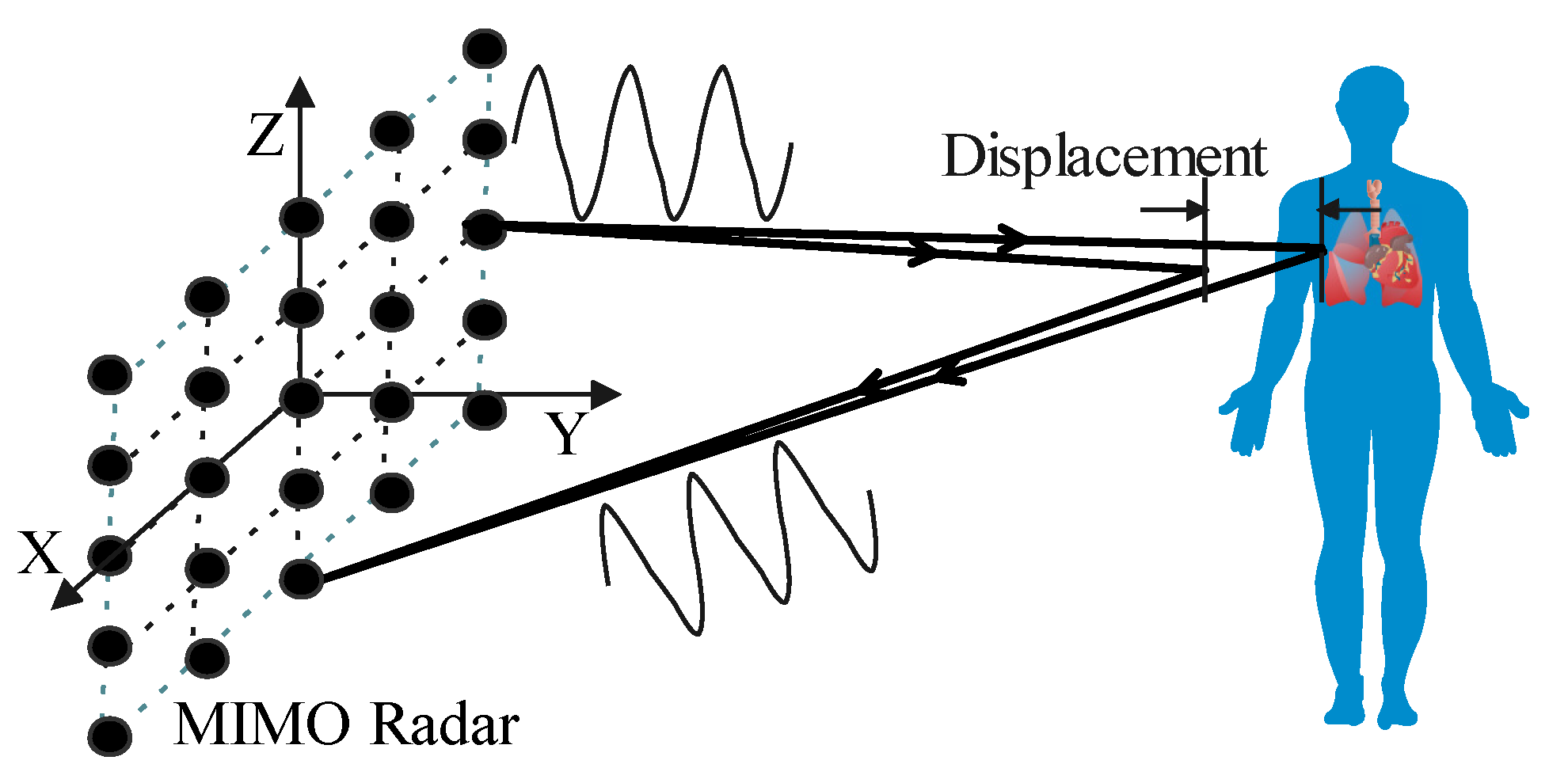
  • We derive the relationship between vital signs signal and radar image in theory. It is proved that the thorax movement caused by respiration and heartbeat is linear with the phase of the radar image. The signal-to-noise ratio (SNR) of the extracted vital signs signal is improved by the factor of radar channel number times frequency number compared with CW Doppler radars;
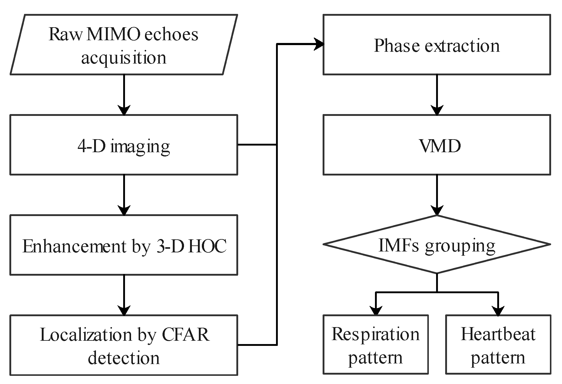
  • We develop a processing scheme for through-wall multi-subject localization and vital signs separation. To localize multiple subjects through the wall, we introduce the higher-order cumulant (HOC) for 3-D radar imaging. The HOC-based localization significantly enhances the human body by suppressing the background clutter;
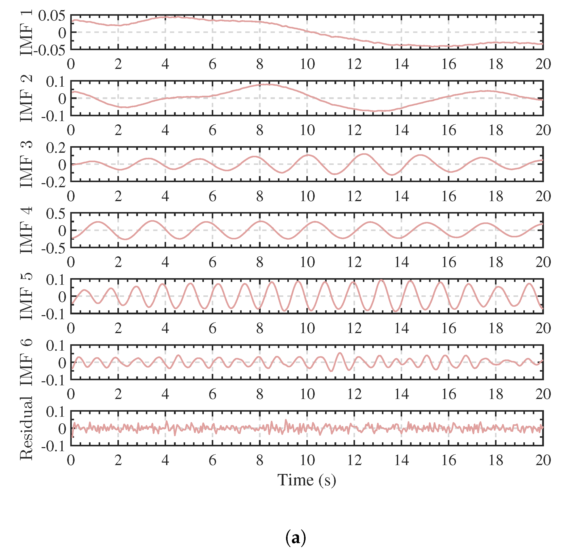
  • We apply the VMD algorithm with a new grouping criterion to adaptively separate the respiration and heartbeat patterns by combining the decomposed intrinsic mode functions (IMFs) and the residual. The grouping criterion exploits the center frequency of each mode to separate the heartbeat pattern from the respiration harmonics.
We organize the rest of this paper as follows. First, we deduce the relationship between the vital signs signal and the radar images. Then we depict the multi-subject detection and localization procedure and apply the VMD algorithm to separate respiration and heartbeat patterns. The third section shows the experimental results of different scenarios for both line-of-sight and through-wall detections. Then in the next section, we discuss the experimental results. At last, we conclude this research.

2. Materials and Methods
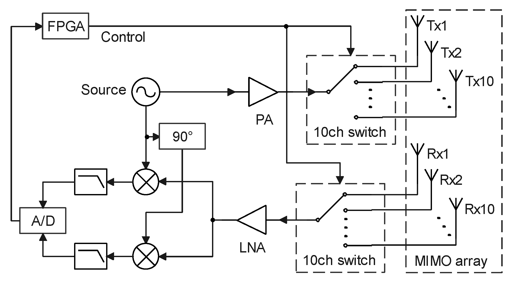
2.1. System Model

Radar-based vital signs detection takes advantage of micro-motion detection technology. The radar system receives echoes scattered from human bodies. The echoes contain motion information of inhalations and exhalations of the lungs, as well as contractions and relaxations of the heart. For typical through-wall radar, the penetration depth into human tissue is less than 10 mm [36]. Consequently, only surface movements of the thorax can be detected. Typical chest wall displacement induced by respiration ranges from 4 mm to 12 mm [37], while the one due to heartbeat lies between 0.2 mm to 0.5 mm [38]. As a result, the displacement of the chest wall identified as the vital signs signal is the superposition of the respiration pattern r r ( t ) and the heartbeat pattern r h ( t ) :
r ( t ) = r r ( t ) + r h ( t )
During radar detection, the position where the transmitted microwave hits the human body varies slightly due to the breathing and heartbeat activities. Thus, the radar receives a series of waveforms with different delays. Then the waveforms are further processed to obtain images of the chest wall at different moments. Radar images are different from one shot to the other when the subjects are alive, so change detection of the image sequence is appropriate for extracting the vital signs. The image here can be one-dimensional (1-D, also called range profile), two-dimensional (2-D), or even three-dimensional (3-D). By exploiting the SFCW UWB radar with a 2-D MIMO array, we can reconstruct 3-D images by frequency-domain back-projection (BP) algorithm. Figure 1 shows the schematic diagram of vital signs detection by MIMO radar imaging. Subjects are within the radiation range of the MIMO radar. The MIMO array transmits and receives electromagnetic waves to form images of the vital body and the background. Due to the chest vibrations, the voxels of the body are slightly different from adjacent images. So we can process the image sequence to monitor vital signs.
Using the 2-D UWB MIMO radar, we execute several measurements consecutively to form 3-D radar images. Then we obtain a series of four-dimensional (4-D) images in the space-time domain. The first three dimensions represent the X, Y, Z coordinates with the origin at the center of the MIMO array, and the fourth dimension represents the time. For the 4-D complex image, the voxel at x q = ( x q , y q , z q ) can be reconstructed by frequency-domain BP as
I ( x q , t ) = l = 1 L m = 1 N T n = 1 N R S m n ( f l ) exp ( j 2 π f l τ q m n )
where the time delay τ q m n is also called the “fast time” delay and t is called the “slow time”. L is the number of stepped frequencies and f c is the center frequency. N T is the number of transmitting elements and N R is the number of receiving elements. S m n ( f l ) is the received signal transmitted by the mth transmitting element located at x m = ( x m , y m , z m ) and received by the nth receiving element located at x n = ( x n , y n , z n ) with the lth stepped frequency f l .
For an ideal point target located at x p = ( x p , y p , z p ) , the received signal can be expressed as S m n ( f l ) = σ ( x p ) exp ( j 2 π f l R p m n / C ) where σ ( x p ) is the reflectivity of the target, C is the velocity of the electromagnetic wave, and R p m n is the round trip distance from the mth transmitting element to the target and the target to the nth receiving element. So Equation (2) can be written as
I ( x q , t ) = l = 1 L m = 1 N T n = 1 N R σ ( x p ) exp ( j 2 π f l R p m n / C ) exp ( j 2 π f l τ q m n ) = l = 1 L m = 1 N T n = 1 N R σ ( x p ) exp j γ l ( R p m n R ^ q m n )
where R q m n = C τ q m n is the round trip distance of the voxel q and γ l = 2 π f l / C is the wave number.
For the voxel where the thorax exists, there is x p = x q + r ( t ) , where r ( t ) = ( r x ( t ) , r y ( t ) , r z ( t ) ) and | | r ( t ) | | = r ( t ) is the displacement of the chest wall. Since the displacement caused by cardiopulmonary activities is far less than the radar distance, it is obvious that | | r | | 2 | | x q | | 2 . Thus, for the human subject facing to the radar array, Equation (3) can be approximated as
I ( x q , t ) = l = 1 L m = 1 N T n = 1 N R σ ( x p ) exp j γ l < x q x m , r ( t ) > | | x q x m | | 2 + < x q x n , r ( t ) > | | x q x n | | 2 N T N R l = 1 L σ ( x p ) exp j 4 π f l r ( t ) / C
where the approximation exists because of the small angle between the vibration and the illumination.
Then the summation vanishes as
I ( x q , t ) = N T N R σ ( x p ) exp j 4 π f c r ( t ) / C sin ( 2 π L Δ f r ( t ) / C ) sin ( 2 π Δ f r ( t ) / C )
Because 2 π Δ f r ( t ) / C is very small for typical through-wall radar parameters, we can simplify the denominator of the last term by small angle approximation:
I ( x q , t ) L N T N R σ ( x p ) exp j 4 π f c r ( t ) / C sin ( 2 π L Δ f r ( t ) / C ) 2 π L Δ f r ( t ) / C = L N T N R σ ( x p ) exp j 4 π f c r ( t ) / C sin c ( 2 π L Δ f r ( t ) / C )
Similarly, the sinc function is approximately equal to 1 for 2 π L Δ f r ( t ) / C 0 . Then the voxel where the chest wall exists can be derived as
I ( x q , t ) L N T N R σ ( x p ) exp j 4 π f c r ( t ) / C = L N T N R σ ( x p ) exp j 4 π f c ( r r ( t ) + r h ( t ) ) / C
There are some advantages, as we can see from Equation (7). Compared with CW Doppler radars, the image by SFCW MIMO has a gain of L N T N R on amplitude because of the coherent accumulation. As a result, the SNR improves by L N T N R for additive noise. Additionally, MIMO radar imaging eliminates the background clutter on the targets by spatial resolutions. According to the radar and array theories, CW Doppler radars do not have any spatial resolution, so the echoes entirely mix the scatterings of targets and backgrounds. SISO UWB radars can distinguish echoes of the targets at different distances because they have a range resolution. However, MIMO radars have spatial resolutions related to their array topology. So we can achieve radar images with targets and backgrounds apart.
From Equation (7), the chest wall displacement is proportion to the phase of the image voxel:
r ( t ) = Phase I ( x q , t ) · C 4 π f c
Since the phase of the voxel is linear to the vital signs signal r r ( t ) + r h ( t ) , this phase-based method avoids interference from the harmonic and intermodulation components. These components can be calculated by Bessel expansion of Equation (7). Because of the non-linear property of the exponential function, the expansion has lots of higher harmonics and mutual harmonics of r r ( t ) and r h ( t ) . The non-linearity makes the detection much more complex. However, the extracted vital signs signal based on phase is a linear combination of the respiration and heartbeat patterns, so it is convenient for further signal processing.
Compared with intensity-based change detection, the vital signs signal extracted by phase information provides the amplitude of thorax displacement. The displacement indicates the intensity of respiration and heartbeat, which shows the vital signs states for daily monitoring and post-quake rescue.
Generally, to obtain the unwrapped phase, we can apply arctangent demodulation (AD) or differentiate and cross multiply (DACM). Here we do not need to calibrate the direct current (DC) offset induced by background clutter, so it overcomes the problem of phase correction, which is significant but not easy to be accurate for CW Doppler radars [35]. In this paper we extract the unwrapped phase according to the extended DACM [39]:
Phase I ( x q , t ) = R ( t ) M ˙ ( t ) R ˙ ( t ) M ( t ) R ( t ) 2 + M ( t ) 2 d t
where R ( t ) and M ( t ) are the real and imaginary components of I ( x q , t ) , i.e., R ( t ) = Real [ I ( x q , t ) ] , M ( t ) = Imag [ I ( x q , t ) ] . R ˙ ( t ) and M ˙ ( t ) represent the derivative of R ( t ) and M ( t ) , respectively. In practice, Equation (9) can be calculated in digital domain.
It is noteworthy that the imaging process is slightly different when the wall exists. For common walls, such as break walls and wooden walls, through-wall attenuation is usually less than 5 dB for electromagnetic waves with frequency less than 3 GHz [28,40], and the wall can be equivalent to a low-pass filter with flat response, so the distortion effect of the wall can be ignored [41]. Figure 2 shows the propagation path for a pair of transmitting and receiving channel in the through-wall case. According to the equivalent propagation model of an electromagnetic wave in the air-wall-air medium [42], the “fast time” delay in Equation (2) increases by an amount related to the wall thickness d w and the relative permittivity ϵ w . Knowing the wall parameters, we can compensate the delay in Equation (3) by adding an extra distance:
Δ R ^ = d w ϵ w sin 2 θ m q cos θ m q + ϵ w sin 2 θ q n cos θ q n
to R ^ q m n , where θ m q is the incident angle on the air–wall interface from the mth transmitting element to the target point q and θ q n is the incident angle on the air–wall interface from the target point q to the nth receiving element. The incident angle is very small for MIMO radar through-wall imaging scenes, so we can approximately compensate the offset distance for multiple channels by an identical value:
Δ R ^ 2 d w ϵ w 1
As a result, the targets behind the wall are corrected to their true positions by an identical compensation for all the imaging voxels, which significantly relieves the computation burden in searching for the incident angles.

2.2. Scheme and Method

This section presents a method to locate and separate vital signs using a UWB MIMO radar. Figure 3 shows the flowchart. First, 3-D imaging is performed sequentially by the BP algorithm, and the HOC of each voxel is calculated to enhance the human targets. Then we utilize the constant false alarm rate (CFAR) to locate multiple subjects. For each detected subject, we extract its phase as the vital signs signal by the extended DACM. Finally, we apply the VMD algorithm with the proposed grouping criterion to separate the respiration and heartbeat patterns. By this method, the positions of multiple subjects can be localized in 3-D space, and the respiration and heartbeat patterns can be extracted and correctly assigned to each individual.

2.2.1. Multiple Subjects Detection and Localization

In the processing flow, we calculate the HOC of the radar images to detect vibrations of the chest wall. The fourth-order cumulant is proper for change detection, which has the potential of suppressing Gaussian noise. This statistic of the image voxel is defined as:
C 4 , I x q ( τ 1 , τ 2 , τ 3 ) = cum { I ( x q , t ) , I ( x q , t + τ 1 ) , I ( x q , t + τ 2 ) , I ( x q , t + τ 3 ) }
where the cum function is defined in [43]. For simplicity, we define the fourth-order cumulant of zero-lag C 4 , I x q ( 0 , 0 , 0 ) as the radar image cumulant H o c ( x q ) . The fourth-order cumulant is not 0 where there exists a human body, while in the background area with Gaussian noise it is 0 in theory.
In practice, the fourth-order cumulant at zero lag C 40 can be calculated efficiently in terms of moments:
C 40 = M 40 3 M 20 2
where M 40 is the fourth-order moment and M 20 is the second-order moment for zero-mean variables. On the other hand, it can be expressed in terms of excess kurtosis and variance:
C 40 = κ ν 2
where κ = M 40 / M 20 2 3 is the excess kurtosis and ν = M 20 is also known as the variance. Equation (14) shows that the fourth-order cumulant of zero-lag takes advantages of both statistics. Compared with the variance-based localization [2,44], the HOC-based method suppresses the Gaussian noise whose excess kurtosis is equal to 0. Compared with the kurtosis-based localization [45], it is much more robust by multiplying the variance. As a result, the localization based on HOC further improves the SNR, which is especially suitable for low SNR cases, such as radar vital signs detection.
By applying CFAR [46] to the radar image cumulant, we can locate the thoraxes. For a given false alarm probability P f a , the adaptive threshold is
Γ ( x q ) = ( P f a 1 / N c 1 ) x q Ω H o c ( x q )
where Ω and N c are the region and number of the reference elements, respectively. To avoid nearby interference, we can specify the nearby elements as protection elements. Then the outer elements are determined as the reference elements. Once obtaining the adaptive threshold, we compare it with each voxel. If the voxel value exceeds the threshold, there exists a target. Otherwise, there is no target. Traversing the 3-D image with a sliding window, we detect the human body occupying a connected region. Then we select the maximum element in each region to extract the vital signs.
Now, the positions of multiple subjects are determined, and the vital signs signals can be extracted by the extended DACM and correctly assigned to the respective individual.

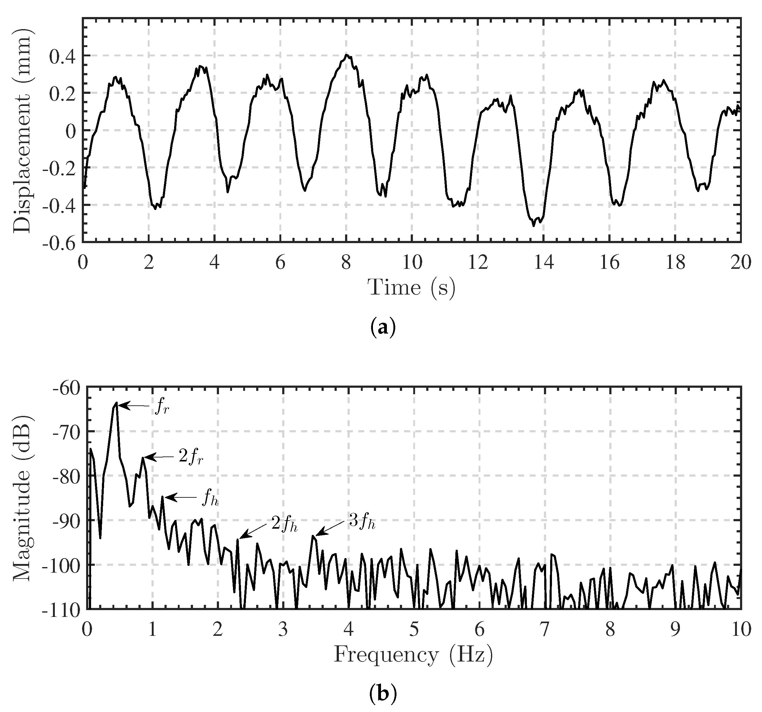
2.2.2. Respiration and Heartbeat Patterns Separation
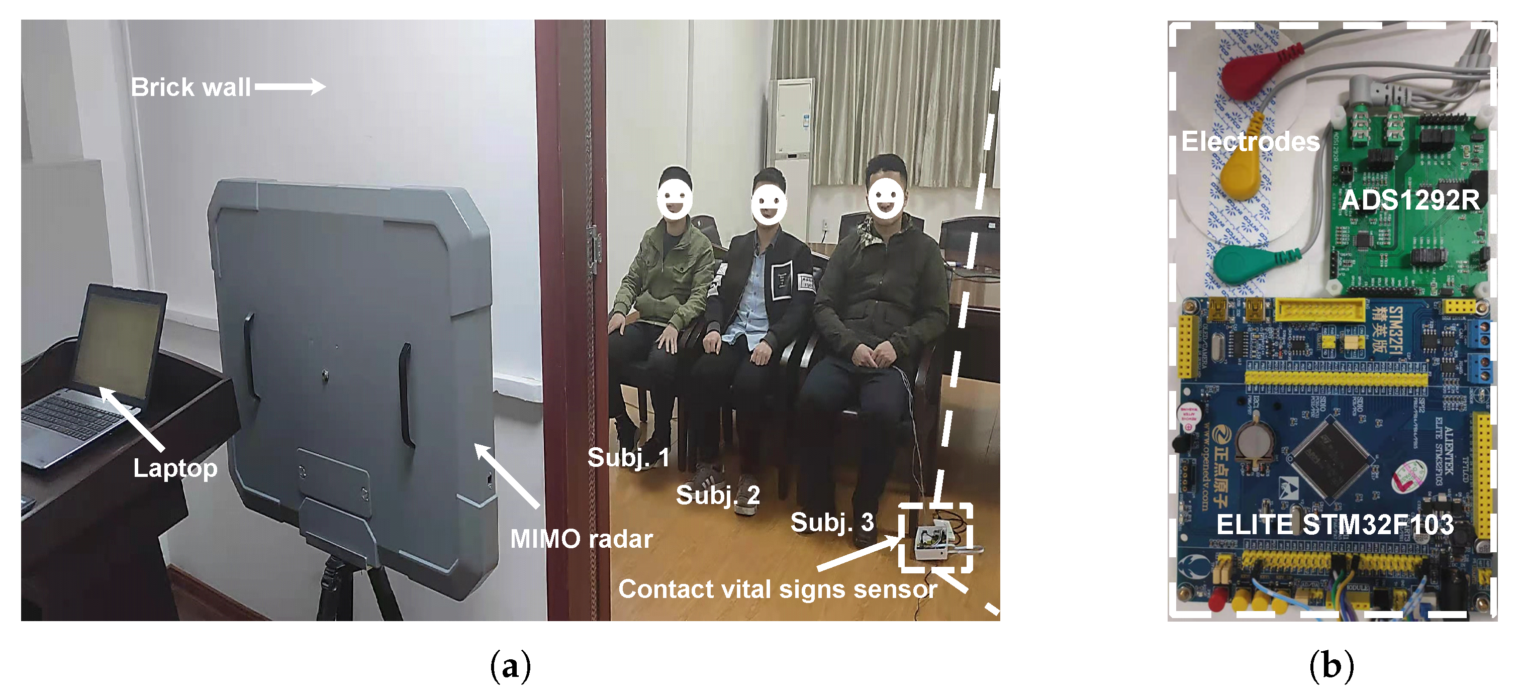
Once each vital signs signal is extracted, we separate the respiration and heartbeat components by the VMD algorithm. The VMD algorithm decomposes the input signal to its IMFs by solving a variational problem [47]. IMFs are amplitude-modulated-frequency-modulated (AM-FM) signals with limited bandwidth. For the input vital signs signal, the IMFs are components of respiration and heartbeat patterns. We group the IMFs and the residual to two sets according to the center frequency of each IMF. According to the empirical knowledge of human cardiopulmonary physiology, the heartbeat components are higher than 0.8 Hz, while the respiration components are usually lower than 0.8 Hz, except for some higher harmonics. Thus, the set with higher frequency IMFs (not respiration harmonics) and the residual reconstructs the heartbeat pattern. The other set reconstructs the respiration pattern. The residual is considered because it consists of higher frequency features of the heartbeat signal. Although we can calculate the HR without the residual, the decomposed IMFs only capture the lower frequency components of the heartbeat signal. However, as we have improved the SNR significantly by MIMO imaging, the noise in the extracted vital signs signal is suppressed, so the residual still contains lots of cardiac information, which contributes to reconstructing the heartbeat pattern.
According to the VMD algorithm, the vital signs signal is decomposed as
r ( t ) = k = 1 K I M F k ( t ) + r e s ( t )
where I M F k ( t ) is the kth IMF, K is the total number of modes, and r e s ( t ) is the residual. According to the empirical RR (0.1 Hz –0.8 Hz ), the IMFs with center frequency ω k equal to or lower than 0.8 Hz and higher than 0.1 Hz belong to the respiration pattern. We define this IMF set as L : = { k | 0.1 < ω k 0.8 } . Here we removes the IMFs lower than 0.1 Hz as the DC component. Additionally, IMFs with center frequency higher than 0.8 Hz are defined as the set H : = { k | ω k > 0.8 } . Then respiration harmonics higher than 0.8 Hz can be expressed as G : = H { k | ω k = ( i + 2 ) ω g , i N , g L } , where i is usually less than 3. So the respiration pattern is combined as
r r ( t ) = k L G I M F k ( t )
The heartbeat pattern is reconstructed as
r h ( t ) = k H G I M F k ( t ) + r e s ( t )
As a result, we separate the vital signs signal to its respiration and heartbeat patterns by VMD with the grouping criterion.

2.3. Experiments

To verify the proposed method and study the performance of the algorithm, we performed a series of experiments in real scenarios. The experiments include line-of-sight and through-wall detections of multiple subjects. Figure 4 illustrates the schematic diagram of the experiments including radar-based and contact-sensor-based vital signs measurements. The line-of-sight detection is similar to the through-wall detection but with no obstacles between the radar and the subjects. Figure 5 presents the real through-wall experiment scenario with the measurement equipment.

2.3.1. Measurement Equipment and Parameters

In this section, the vital signs monitoring system used in the experiments is introduced. As shown in Figure 5a, the vital signs monitoring system consists of a through-wall MIMO radar prototype, a contact vital signs sensor, and a laptop for signal processing. The MIMO radar prototype is a portable all-solid-state radar, which packages 10 transmitting elements and 10 receiving elements in a 90 c m × 20 c m × 70 c m box. Figure 6 depicts the block diagram of the MIMO radar system. The MIMO array has 10 × 10 = 100 virtual array elements corresponding to 100 transmitting and receiving channels. All the channels successively send and receive SFCW signals to create radar images. Thereby, 4-D information can be obtained with 3-D spatial positions and 1-D time indexes. The duration for one scan is 50 ms so the measurements run with a frame rate of 20 Hz. Table 2 lists the key parameters of the MIMO radar prototype.
The contact vital signs sensor provides reference signals, such as ECG and respiration signals, which are the gold standards for respiration and heartbeat measurements. It consists of a biological potential measurement chip (ADS1298R, Texas Instruments) module and an embedded circuit board (ELITE STM32F103, ALIENTEK). ADS1298R is used for recording ECG and respiration impedance. The embedded circuit board is used for data acquisition. Figure 5b shows the contact vital signs sensor together with three electrodes. In the experiments, the subject under test wears the three-lead electrodes linking to the contact sensor. The connected laptop deals with both the non-contact radar data and the contact sensor data. Meanwhile, it synchronizes the data with time stamps.

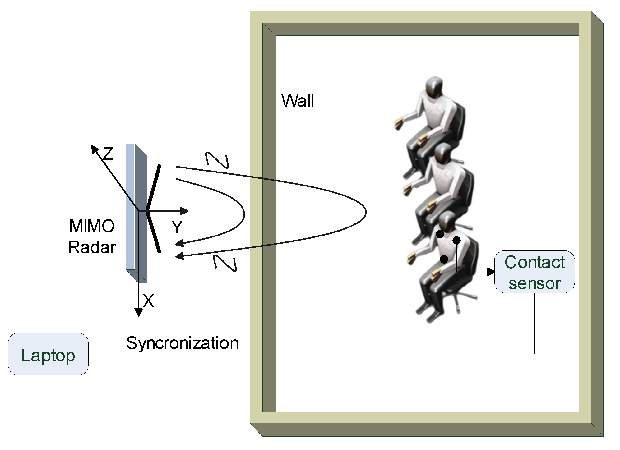
2.3.2. Measurements Setup and Scenarios

We carried out two different kinds of experiments to verify the proposed method: (1) line-of-sight multi-subject measurements; and (2) through-wall multi-subject measurements. All the experiments were implemented in an indoor office building. In each experiment, the radar was installed on a tripod and placed vertically. The MIMO array faced toward the human targets, and its center was 1.0 m above the ground. Three male adults were tested. Subject 1 is 27 years old and 1.75 m tall with a weight of 73 kg. Subject 2 is 25 years old and 1.71 m tall with a weight of 60 kg. Subject 3 is 32 years old and 1.78 m tall with a weight of 65 kg.
In the scene without a wall between the radar and the subjects, we executed the multi-subject measurements. Three human subjects sat side by side toward the radar. The distance between every two subjects was 0.5 m, and the distance between each subject and the radar was 2.5 m. One of the subjects wore the contact respiration and heartbeat sensor. The laptop recorded the radar data and the contact data concurrently.
In the case of through-wall measurements, the MIMO radar was placed 0.2 m in front of the wall, and the three subjects sat side by side facing toward the radar. The distance between every two subjects was 0.5 m, and the distance between each subject and the wall was 1.8 m. Figure 5a shows the experimental scenario of the through-wall multi-subject vital signs measurements. The wall is made of bricks with a thickness of 12 cm and a relative permittivity of 5.1. The through-wall attenuation is less than 5 dB for electromagnetic waves with frequencies lower than 3 GHz. To avoid the interference of random body motion, the persons under test in all experiments sat steadily in resting states.

3. Results

We checked three groups of experimental results. The first group shows the multi-subjects localization results in both line-of-sight and through-wall cases. The second group displays the separation results of respiration and heartbeat patterns. Then the third group assesses the monitoring performance in both cases.

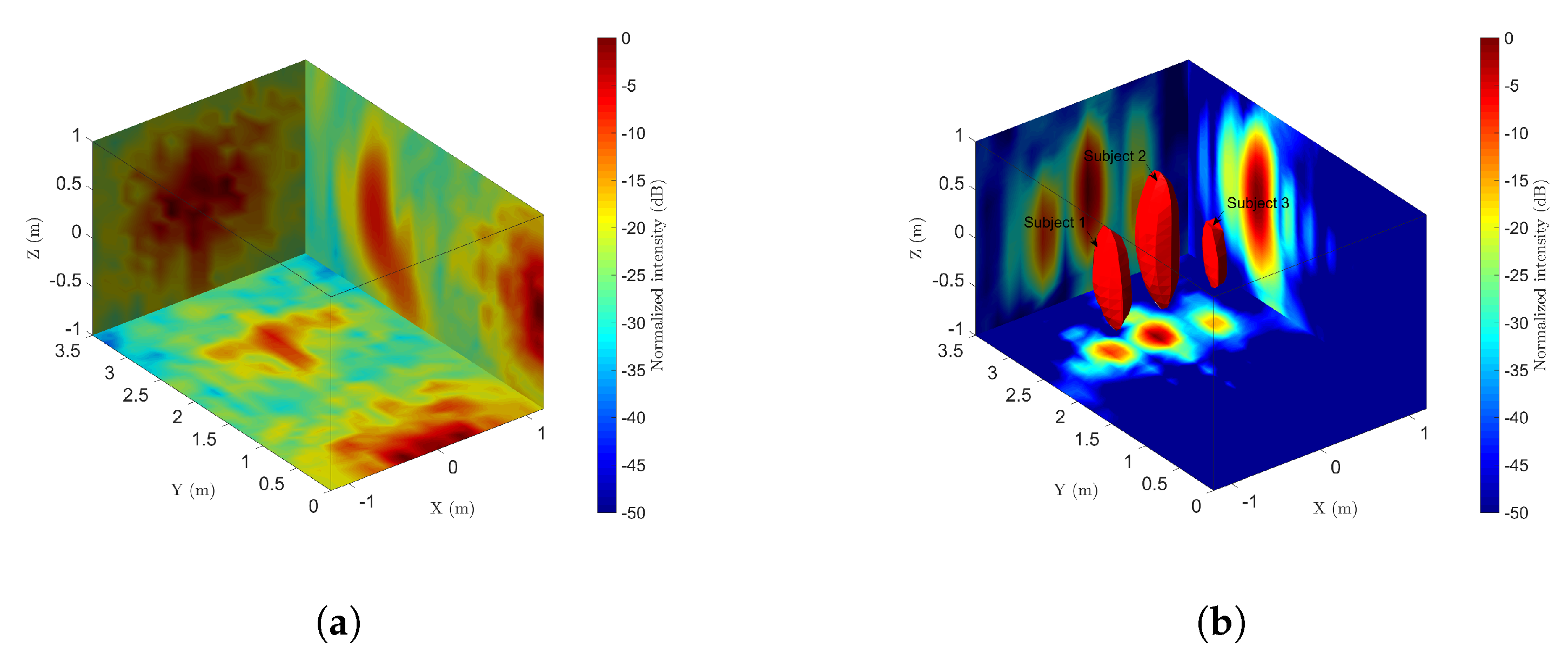
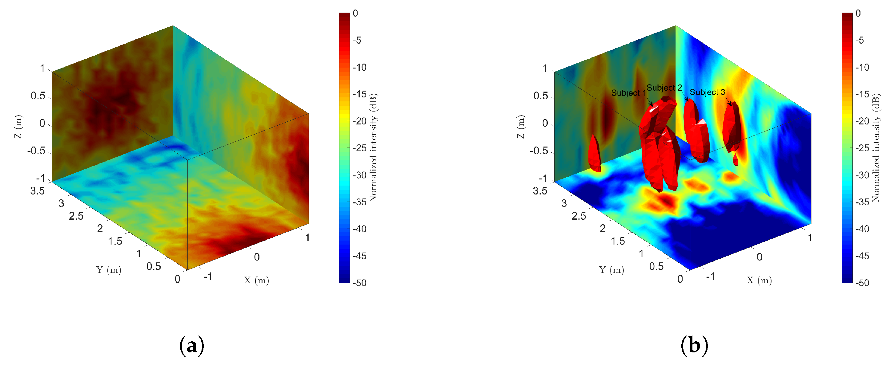
3.1. Detection and Localization Results

With high resolutions in azimuth (X-axis), range (Y-axis), and pitch (Z-axis), the 2-D UWB MIMO radar can detect multiple targets in 3-D space simultaneously. In the line-of-sight experiments, the MIMO radar recorded 10 seconds of data at first. Figure 7a shows one frame of the BP imaging results of three persons. It is difficult to identify the persons directly. However, as shown in Figure 7b, the fourth-order cumulant helps to detect and localize the human targets successfully. The voxel intensities of the cumulant reflect the vibrations of the human body caused by breathing and heartbeat activities. For a harmonic signal modeled as the vital signs signal, the fourth-order cumulant at zero lag is C 40 = 3 8 i A i 4 , where A i is the vibration amplitude of the sinusoidal component [48]. Thus, the greater the amplitude of respiration and heartbeat, the greater the absolute value of fourth-order cumulant. Figure 7b indicates that Subject 2 has heavier breathing than the other two subjects. As a result, there are three targets detected through CFAR in the fourth-order cumulant image. Then the position of each subject is determined by the strongest voxel in each connected region.
In the through-wall case, Figure 8a shows the direct 3-D BP image. Although the microwave penetrates the brick wall, the subjects are sheltered by the wall and the direct wave tailing. So it is hard to detect the subjects behind the wall. By performing the fourth-order cumulant along the slow time, the wall clutter and noise are suppressed significantly. Figure 8b shows the results of fourth-order cumulant with three subjects in the image. The 3-D shape of the cumulant is slightly distorted compared with Figure 7, but all three subjects are still revealed.
Table 3 shows the coordinates of estimated human positions in both cases. The center of the nipple line on the chest wall is measured as the true position. We also demonstrate the estimated errors, which are the coordinate offsets relative to the true position. As the vibrations exist on the whole surface of the thorax, the offsets mainly exist on the XZ-plane. The errors are smaller than the size of the thorax so that the results are acceptable. Compared with the line-of-sight localization, it has larger errors in the through-wall case because of the distortion of the image.

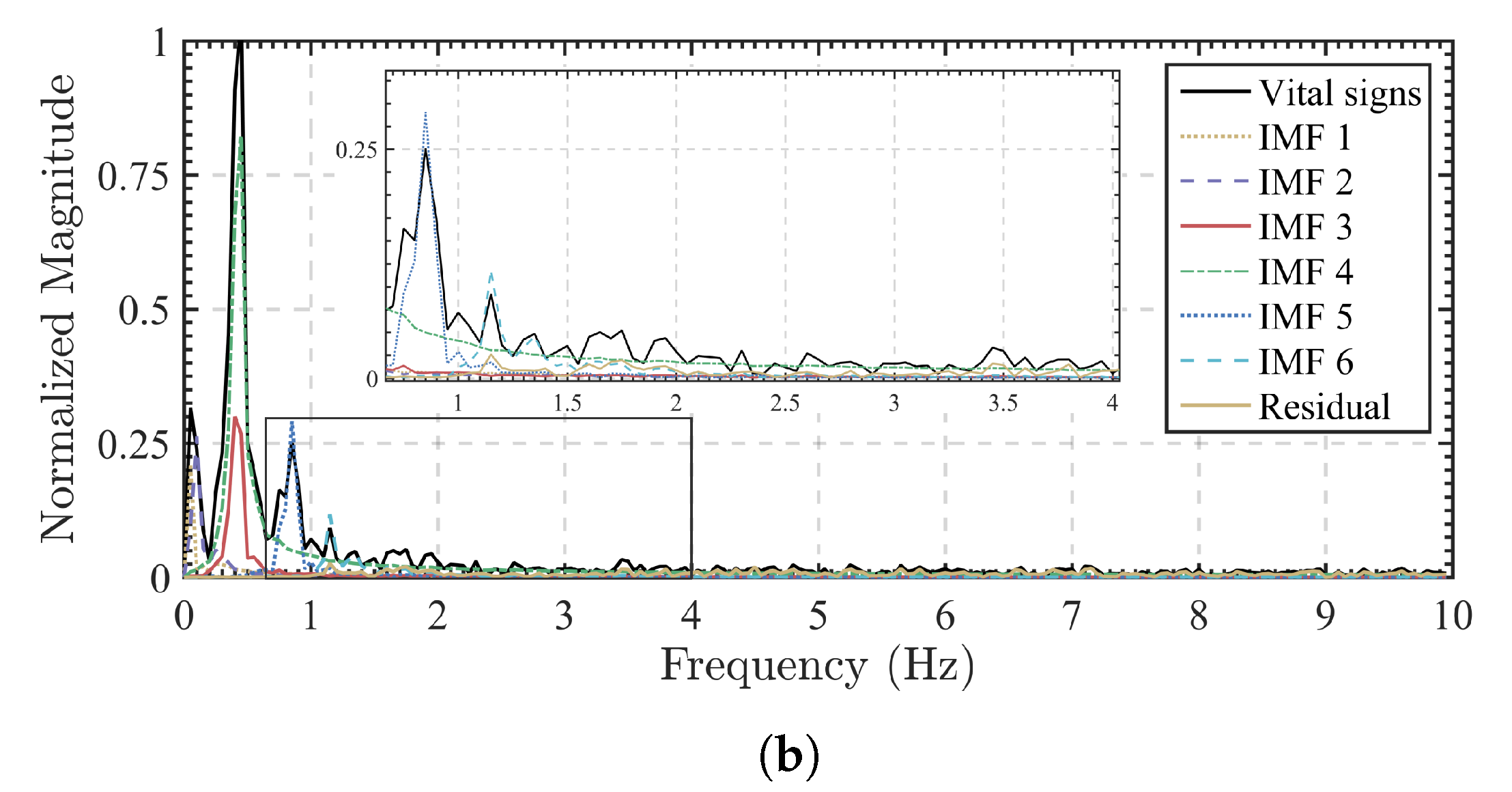
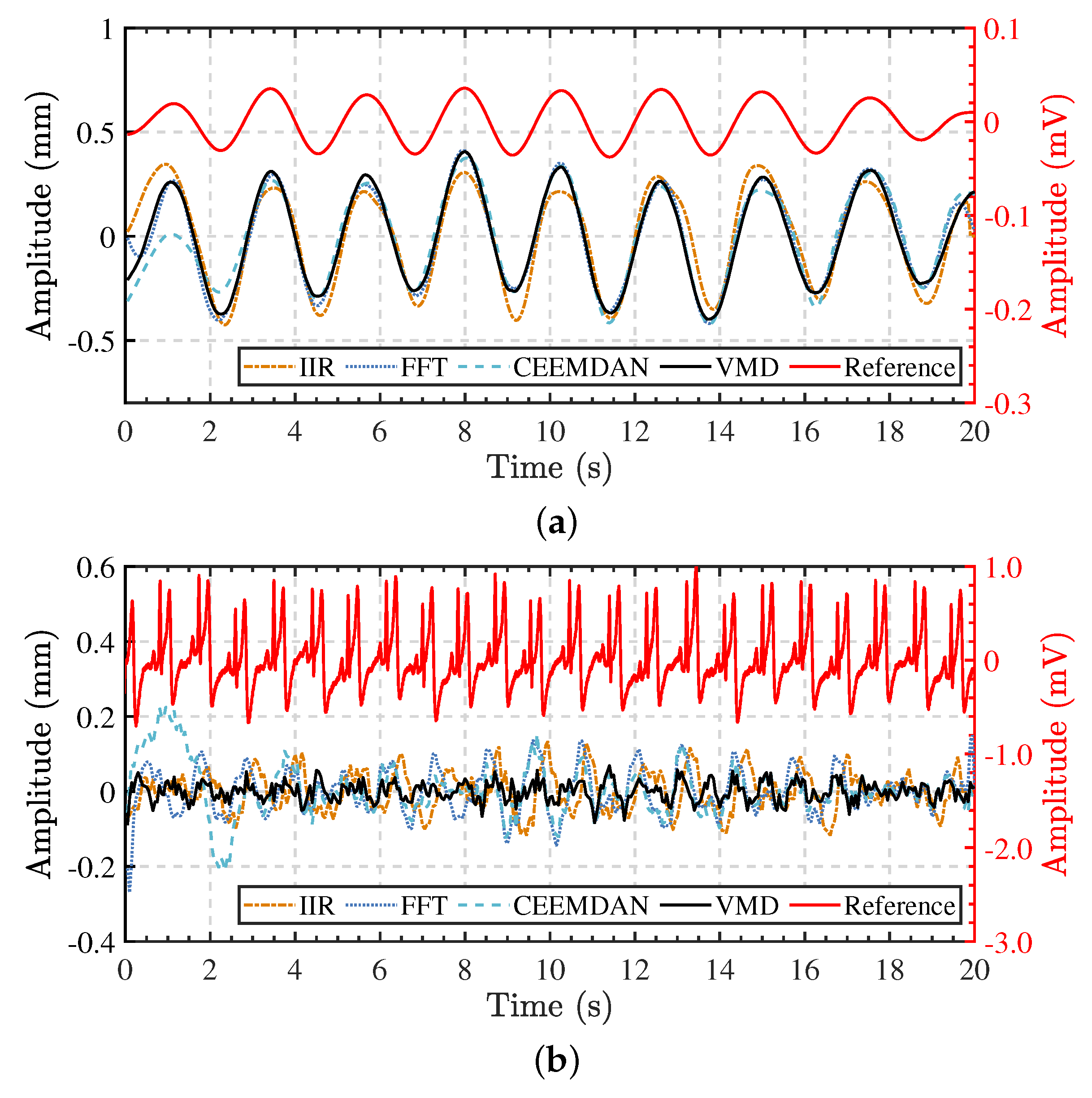
3.2. Vital Signs Separation Results

After localizing the subjects, we extract the vital signs signal for each person, respectively. Figure 9a shows the extracted vital signs signal of Subject 1 for 20 s in line-of-sight case. The peak-to-peak displacement is about 0.9 mm and the breaths are obvious. However, It is hard to identify the heartbeats in the vital signs signal. From the power spectrum magnitude in Figure 9b, the respiration fundamental frequency is about 0.425 Hz and the second harmonic is significant at 0.85 Hz. The heartbeat fundamental frequency is 1.150 Hz and it is about 20 dB lower than the respiration fundamental.
We separate the respiration and heartbeat signals by the VMD algorithm with the proposed grouping criterion and compare the results with the reference signals obtained by the contact sensor. To initialize the VMD algorithm, we set the number of modes to 6 and the moderate bandwidth constraint to 10,000. In the VMD algorithm, the number of modes is usually preset due to priori information. According to the component of the vital signs signal empirically, including 4 respiration harmonics, it works well to set the number of modes to 6. Too few modes lead to mixture of the respiration harmonics and the heartbeat fundamentals, while too many modes split the respiration and heartbeat components to artificial modes. Generally, a greater modes number is better than a smaller one but brings more complexity. We also determine the initial center frequencies to be uniformly distributed and the tolerance of convergence criterion to 10 10 .
For the vital signs signal in Figure 9, the decomposition results are shown in Figure 10a and the corresponding spectrum of each IMFs are given in Figure 10b. The center frequencies of IMF 1 and IMF 2 are lower than 0.1 Hz, so they are regarded as random body movements. IMF 3 and IMF 4 are in the respiration frequency range. IMF 5 and IMF 6 are in the heartbeat frequency range. However, IMF 5 is the second harmonic of IMF 4. According to the grouping criterion, IMF 3–5 belong to the respiration pattern, while IMF 6 and the residual term belong to the heartbeat pattern. Then the respiration and heartbeat patterns are obtained after the combination.
The respiration and heartbeat patterns are reconstructed by grouping and combining the IMFs. For the vital signs signal in Figure 9, Figure 11 shows the separated results compared with the contact sensor, as well as some other algorithms. For the VMD algorithm, the separated respiration pattern and the reference signal are highly consistent in periods. The peak-to-peak amplitude is about 0.9 mm, and the RR is about 25 breaths per minute through peak detection. It is clear to see the exhalation and inhalation and their state transition during breathing. Similarly, we compare the separated heartbeat pattern with the reference ECG signal. As shown in Figure 11b, the peak-to-peak amplitude of chest wall vibration caused by heartbeat is about 0.1 mm, and the HR is 69 bpm (1.15 Hz). The heartbeat pattern shows high similarity from one beat to another. From adjacent beats, we can obtain the instantaneous HR. The shape of each beat also shows the features of heart contraction and relaxation, which provides a high-quality signal for subsequent feature extraction.
Meanwhile, for comparison we also implement some other algorithms such as infinite impulse response (IIR) filtering, FFT-based ideal band-pass filtering [34], and complete ensemble empirical mode decomposition with adaptive noise (CEEMDAN) [49,50]. The results are shown in Figure 11. For all these algorithms, the separated respiration patterns are consistent with the reference signal. The separated heartbeat pattern by CEEMDAN has similar periods except for a bit of time at the beginning. However, the heartbeat patterns separated by IIR and FFT-based filtering show wrong results. The results can be explained according to the implementation of each algorithm. In the IIR filtering algorithm, a fourth-order IIR filter with a passband of 0.1 Hz –0.8 Hz filters the displacement signal to obtain the respiration component, and an eighth-order IIR bandpass filter with a passband of 0.8 Hz –10 Hz filters the heartbeat component out. This algorithm is simple and efficient. It is effective in situations when a person breathes slowly. When the breathing is fast, the spectrum of the respiration component exceeds the cutoff frequency so that the heartbeat component is mixed with the respiration component. In this instance, the second respiration harmonic happens to be at 0.85 Hz, so the filter regards it as a part of the heartbeat component. As a result, the real heartbeats are obscured by the respiration harmonics. The FFT-based ideal bandpass filter is a frequency-domain algorithm. Firstly we transform the extracted vital signs signal by FFT and then apply the ideal rectangular window function to the spectrum. The window cutoff frequencies are 0.1 Hz –0.8 Hz for the respiration signal and 0.8 Hz –10 Hz for the heartbeat signal. At last, the inverse FFT is applied to the filtered spectra to obtain the time-domain signals. By exploiting these operations, the heartbeat pattern can be separated from the respiration pattern. In addition to having the same problem as in the IIR filtering, this algorithm also has the disadvantage of spectrum leakage caused by FFT. The spectrum energy spreads around the true frequencies, and the rigid cutoff frequency may divide the respiration component as the heartbeat component. CEEMDAN is an improved empirical mode decomposition (EMD) algorithm to decompose signals to their IMFs. This improved EMD-based algorithm overcomes the mode mixing effect of the EMD algorithm to some extent, and it is more efficient and stable than the ensemble empirical mode decomposition (EEMD) algorithm [49]. For the parameters in the CEEMDAN, the noise standard deviation is 0.1, and the number of realizations is 100. We combine the IMFs with the prominent peak in the range of 0.1 Hz –0.8 Hz as the respiration component and the IMFs with the prominent peak in the range of 0.8 Hz –10 Hz as the heartbeat component.
As apnea may occur during vital signs monitoring, we also display the extracted vital signs signal of Subject 2, who holds his breath at the 12th second. As shown in Figure 12, the vital signs signal captures the change of breathing. Apnea reveals the heartbeat without the effect of respiration, while with normal breathing, it is hard to identify the heartbeat directly. However, by the VMD algorithm, we separate the respiration and heartbeat patterns in both conditions.
Moreover, as shown in Figure 13, we extracted the vital signs signals of the three subjects behind the wall and separated the respiration and heartbeat patterns by the proposed method. The through-wall vital signs signals are similar to the line-of-sight one in Figure 9. From the separated respiration and heartbeat patterns, it is easy to calculate the corresponding RR and HR. The amplitudes also show the intensities of the vital signs. Additionally, we can assign each respiration pattern and heartbeat pattern to the related subject. Thus, we achieve the goal to detect the vital signs of multiple subjects behind the wall.
The separated components are promising estimations of respiration and heartbeat patterns. We detect the peak intervals at each breath to monitor the RR for both radar-based and contact-sensor-based signals. To obtain the instantaneous HR by the MIMO radar, we perform short-term autocorrelation with a sliding window to calculate the heartbeat period [51]. The length of the window function is 2 s and the step is 0.1 s. The R-R peak intervals of the ECG signal provide the ground truth of HR. Figure 14 shows the RR and HR monitoring results of 40 s in both cases. The curves based on the radar are in good agreement with the reference signals. In Figure 14a, the RR values are not detected after the 12th s because the subject holds his breath, while the HR monitoring continues with correct values.
For statistical analysis, we further recorded 600 s of data for the three subjects. Table 4 shows the root mean square error (RMSE) of RR and HR of the three subjects for both line-of-sight and through-wall cases. The RMSE is defined as
R M S E = 1 N n = 1 N ( r r a d a r r r e f ) 2
where N is the number of samples, r r a d a r is the RR obtained by radar and r r e f is the reference RR for calculating the RMSE of RR. Similarly, when calculating the RMSE of HR, r r a d a r is the HR obtained by radar and r r e f is the reference HR. In each case, the RMSE of RR is lower than 2 bpm because of the high quality of the recovered respiration patterns. The RMSE of HR is higher for through-wall detection because of the wall attenuation. However, the overall performance degrades less than 2 bpm owing to the strong penetration property of the low-frequency microwave.

4. Discussion

This research presents the localization and vital signs monitoring of multiple subjects behind a wall. Theoretical derivation and experiments show that the coherent imaging method greatly improves the SNR. The HOC further suppresses the noises, which is helpful to achieve accurate micro-motion measurement in the case of low SNR, such as through-wall detection.
By radar imaging, multiple human bodies can be detected and localized. The chest wall vibrations caused by cardiopulmonary movements can be obtained by extracting the phase of the subject image. The HOC results also suggest a potential to estimate the chest shape and the posture of the human body. The vibrations caused by breathing distribute in the torso, while the vibrations caused by heartbeats not only exist on the surface of the chest but also on the head and limbs [52]. Thus, the shape of the torso or even the body can be retrieved by vibration detection. However, radar imaging with higher resolution is necessary to improve accuracy.
The vibrations contain the vital signs information of respiration and heartbeat. However, the two vital signs signals are superimposed together. Unlike extracting the respiration signal from the ECG signal, the amplitude of the respiration signal is much larger than that of the heartbeat signal. Therefore, the separation of respiration and heartbeat signals can be summarized as the problem of separating higher-frequency weaker signals from lower-frequency stronger ones. The critical problem is how to separate the heartbeat pattern from the respiration pattern without interference from respiration harmonics. Although simple and efficient, the IIR and FFT-based ideal bandpass filtering cannot effectively distinguish heartbeat patterns from respiration harmonics. When the breath is fast, the harmonics of the respiration signal are close to the heartbeat fundamental in the frequency domain. The CEEMDAN algorithm also has the potential to separate the respiration and heartbeat patterns with the proposed criterion, but the computation complexity is much higher than VMD. In our VMD algorithm, we need to determine the number of modes in advance. Too few modes will lead to the mixing of heartbeat patterns and respiration harmonics, while too many modes may produce fake IMFs. According to the waveforms of respiration and heartbeat patterns, the empirical number of modes is around 6. Different from identifying a single pattern as the respiration or heartbeat signal [50], VMD with the grouping criterion combines multiple decomposed patterns to attain respiration and heartbeat patterns, which retains the details of the heartbeat signal. The separated signals lay a good foundation for subsequent classification and recognition processing.
Due to the non-stationarity of vital signs, it is more difficult to separate respiration and heartbeat patterns when breathing changes rapidly. In the grouping criterion, we compare the central frequency of the mode with the fundamental frequency of respiration to determine which modes are respiration harmonics. When breathing changes rapidly, the central frequency of the mode containing respiration harmonics may not be equal to an integer multiple of the respiration fundamental, so it becomes more difficult to identify respiration harmonics. One solution is to expand the range of higher-order harmonic frequency. However, it may cause the heartbeat signal component to be identified as respiration harmonics. Using the idea of short-time Fourier transform (STFT) for reference, the non-stationary signal can be processed by shortening the observation time.
It is important to highlight that human behaviors have an impact on radar-based detection. Different body orientations may cause different vital signs to be extracted, but they still contain breathing and heartbeat signals. Arterial pulse have been extracted by radar-based measurements of the displacements from the back and calf of the human body [52]. Although the proportions of breathing and heartbeat signals vary for different body orientations, rhythmic components containing respiration and heartbeat information remain in the displacement signals. Moreover, random body movement may cause incorrect results of vital signs monitoring. As shown in Figure 14d, the HR values of both curves are almost the same except for 2 s after the 17th second. It is caused by a random movement of the torso. Eliminating the influence of random body movements is still a difficult problem in the radar-based vital signs monitoring application. Large body movement severely whelms the vital signs, while small body movement can be considered as a superposed low-frequency component. Fortunately for the stationary subject, the random body movement is so insignificant that it can be decomposed as IMFs with low frequencies. These effects require a further research for continuous monitoring of vital signs in different situations.

5. Conclusions

In this paper, we use a low-frequency ultra-wideband MIMO radar for through-wall vital signs localization and detection. The derivation shows the essential relationship between chest displacements and radar images. Compared with CW Doppler radars, SFCW MIMO imaging improves the SNR critically by the factor of the radar channel number times the frequency number. From successive radar imaging, we locate the multiple subjects by HOC and CFAR. Then we extract the phase of radar images as the vital signs signal. We also exploit the VMD algorithm with a grouping criterion to separate the heartbeat signal from the respiration signal. As the experimental results in different scenarios have shown, the proposed method can track multiple subjects and monitor their RR and instantaneous HR, even under the condition of through-wall detection. In some other non-contact health monitoring applications, we believe that the proposed method is also suitable for vital signs detection by mmWave radars with higher resolutions. In addition to RR and HR, as we have obtained the patterns of respiration and heartbeat, we will attempt to classify and identify the vital signs in further research.

Author Contributions

Conceptualization, Z.L. and T.J.; methodology, Z.L.; software, Y.S. and Z.L.; validation, Z.L. and Y.D.; formal analysis, Y.D.; investigation, Z.L.; resources, Y.S.; data curation, Z.L.; writing—original draft preparation, Z.L.; writing—review and editing, Z.L. and Y.D.; visualization, Z.L.; supervision, T.J.; project administration, T.J.; funding acquisition, T.J. All authors have read and agreed to the published version of the manuscript.

Funding

This research was funded by the National Natural Science Foundation of China, grant number 61971430 entitled “Study on ultra-wideband radar gait recognition technique”.

Institutional Review Board Statement

Not applicable.

Informed Consent Statement

Not applicable.

Data Availability Statement

Data sharing not applicable.

Conflicts of Interest

The authors declare no conflict of interest.

Abbreviations

The following abbreviations are used in this manuscript:
ADArctangent demodulation
BSSBlind source separation
BPBack-projection
CEEMDANComplete ensemble empirical mode decomposition with adaptive noise
CFARConstant false alarm rate
CWContinuous-wave
DACMDifferentiate and cross multiply
DCDirect Current
ECGElectrocardiogram
EMDEmpirical mode decomposition
EEMDEnsemble empirical mode decomposition
FMCWFrequency-modulated continuous-wave
HOCHigher-order cumulant
HRHeart rate
IIRInfinite impulse response
IMFIntrinsic mode function
IR-UWBImpulse radio ultra-wideband
MIMOMultiple-input multiple-output
RMSERoot mean square error
RRRespiratory rate
SFCWStepped-frequency continuous-wave
STFTShort-time Fourier transform
SIMOSingle-input multiple-output
SNRSignal-to-noise ratio
UWBUltra-wideband
VMDVariational mode decomposition

References

  1. Clemente, C.; Balleri, A.; Woodbridge, K.; Soraghan, J.J. Developments in Target Micro-Doppler Signatures Analysis: Radar Imaging, Ultrasound and through-the-Wall Radar. EURASIP J. Adv. Signal Process. 2013, 2013, 47. [Google Scholar] [CrossRef] [Green Version]
  2. Liang, S.D. Sense-through-Wall Human Detection Based on UWB Radar Sensors. Signal Process. 2016, 126, 117–124. [Google Scholar] [CrossRef]
  3. Thi Phuoc Van, N.; Tang, L.; Demir, V.; Hasan, S.F.; Duc Minh, N.; Mukhopadhyay, S. Review-Microwave Radar Sensing Systems for Search and Rescue Purposes. Sensors 2019, 19, 2879. [Google Scholar] [CrossRef] [PubMed] [Green Version]
  4. Li, C.; Lubecke, V.M.; Boric-Lubecke, O.; Lin, J. Sensing of Life Activities at the Human-Microwave Frontier. IEEE J. Microwaves 2021, 1, 66–78. [Google Scholar] [CrossRef]
  5. Li, C.; Cummings, J.; Lam, J.; Graves, E.; Wu, W. Radar Remote Monitoring of Vital Signs. IEEE Microw. Mag. 2009, 10, 47–56. [Google Scholar] [CrossRef]
  6. Li, C.; Peng, Z.; Huang, T.Y.; Fan, T.; Wang, F.K.; Horng, T.S.; Munoz-Ferreras, J.M.; Gomez-Garcia, R.; Ran, L.; Lin, J. A Review on Recent Progress of Portable Short-Range Noncontact Microwave Radar Systems. IEEE Trans. Microw. Theory Tech. 2017, 65, 1692–1706. [Google Scholar] [CrossRef]
  7. Cerasuolo, G.; Petrella, O.; Marciano, L.; Soldovieri, F.; Gennarelli, G. Metrological Characterization for Vital Sign Detection by a Bioradar. Remote Sens. 2017, 9, 996. [Google Scholar] [CrossRef] [Green Version]
  8. Will, C.; Shi, K.; Schellenberger, S.; Steigleder, T.; Michler, F.; Fuchs, J.; Weigel, R.; Ostgathe, C.; Koelpin, A. Radar-Based Heart Sound Detection. Sci. Rep. 2018, 8, 11551. [Google Scholar] [CrossRef] [PubMed] [Green Version]
  9. Lazaro, A.; Girbau, D.; Villarino, R. Analysis of Vital Signs Monitoring Using an IR-UWB Radar. Prog. Electromagn. Res. 2010, 100, 265–284. [Google Scholar] [CrossRef] [Green Version]
  10. Pisa, S.; Pittella, E.; Piuzzi, E. A Survey of Radar Systems for Medical Applications. IEEE Aerosp. Electron. Syst. Mag. 2016, 31, 64–81. [Google Scholar] [CrossRef]
  11. Cardillo, E.; Caddemi, A. A Review on Biomedical MIMO Radars for Vital Sign Detection and Human Localization. Electronics 2020, 9, 1497. [Google Scholar] [CrossRef]
  12. Adib, F.; Mao, H.; Kabelac, Z.; Katabi, D.; Miller, R.C. Smart Homes That Monitor Breathing and Heart Rate. In Proceedings of the 33rd Annual ACM Conference on Human Factors in Computing Systems-CHI ’15; ACM Press: Seoul, Korea, 2015; pp. 837–846. [Google Scholar] [CrossRef]
  13. Ha, U.; Assana, S.; Adib, F. Contactless Seismocardiography via Deep Learning Radars. In Proceedings of the 26th Annual International Conference on Mobile Computing and Networking; ACM: London, UK, 2020; pp. 1–14. [Google Scholar] [CrossRef]
  14. Xia, Z.; Shandhi, M.M.H.; Li, Y.; Inan, O.; Zhang, Y. The Delineation of Fiducial Points for Non-Contact Radar Seismocardiogram Signals without Concurrent ECG. IEEE J. Biomed. Health Inform. 2020, 1031–1040. [Google Scholar] [CrossRef] [PubMed]
  15. Xia, Z.; Shandhi, M.M.H.; Inan, O.T.; Zhang, Y. Non-Contact Sensing of Seismocardiogram Signals Using Microwave Doppler Radar. IEEE Sensors J. 2018, 18, 5956–5964. [Google Scholar] [CrossRef]
  16. Wang, D.; Yoo, S.; Cho, S.H. Experimental Comparison of IR-UWB Radar and FMCW Radar for Vital Signs. Sensors 2020, 20, 6695. [Google Scholar] [CrossRef] [PubMed]
  17. Islam, S.M.M.; Yavari, E.; Rahman, A.; Lubecke, V.M.; Boric-Lubecke, O. Separation of Respiratory Signatures for Multiple Subjects Using Independent Component Analysis with the JADE Algorithm. In Proceedings of the 2018 40th Annual International Conference of the IEEE Engineering in Medicine and Biology Society (EMBC), Honolulu, HI, USA, 18–21 July 2018; pp. 1234–1237. [Google Scholar] [CrossRef]
  18. Ding, C.; Yan, J.; Zhang, L.; Zhao, H.; Hong, H.; Zhu, X. Noncontact Multiple Targets Vital Sign Detection Based on VMD Algorithm. In Proceedings of the 2017 IEEE Radar Conference (RadarConf), Seattle, WA, USA, 8–12 May 2017; pp. 727–730. [Google Scholar] [CrossRef]
  19. Rong, Y.; Bliss, D.W. Harmonics-Based Multiple Heartbeat Detection at Equal Distance Using UWB Impulse Radar. In Proceedings of the 2018 IEEE Radar Conference (RadarConf18), Oklahoma City, OK, USA, 23–27 April 2018; pp. 1101–1105. [Google Scholar] [CrossRef]
  20. Singh, A.; Rehman, S.U.; Yongchareon, S.; Chong, P.H.J. Multi-Resident Non-Contact Vital Sign Monitoring Using Radar: A Review. IEEE Sensors J. 2021, 21, 4061–4084. [Google Scholar] [CrossRef]
  21. Lee, H.; Kim, B.H.; Park, J.K.; Yook, J.G. A Novel Vital-Sign Sensing Algorithm for Multiple Subjects Based on 24-GHz FMCW Doppler Radar. Remote Sens. 2019, 11, 1237. [Google Scholar] [CrossRef] [Green Version]
  22. Yang, Y.; Cao, J.; Liu, X.; Liu, X. Multi-Breath: Separate Respiration Monitoring for Multiple Persons with UWB Radar. In Proceedings of the 2019 IEEE 43rd Annual Computer Software and Applications Conference (COMPSAC), Milwaukee, WI, USA, 15–19 July 2019; pp. 840–849. [Google Scholar] [CrossRef]
  23. Mercuri, M.; Lorato, I.R.; Liu, Y.H.; Wieringa, F.; Hoof, C.V.; Torfs, T. Vital-Sign Monitoring and Spatial Tracking of Multiple People Using a Contactless Radar-Based Sensor. Nat. Electron. 2019, 2, 252–262. [Google Scholar] [CrossRef]
  24. Xiong, J.; Hong, H.; Zhang, H.; Wang, N.; Chu, H.; Zhu, X. Multitarget Respiration Detection With Adaptive Digital Beamforming Technique Based on SIMO Radar. IEEE Trans. Microw. Theory Tech. 2020, 68, 4814–4824. [Google Scholar] [CrossRef]
  25. Shang, X.; Liu, J.; Li, J. Multiple Object Localization and Vital Sign Monitoring Using IR-UWB MIMO Radar. IEEE Trans. Aerosp. Electron. Syst. 2020, 56, 4437–4450. [Google Scholar] [CrossRef]
  26. Walterscheid, I.; Biallawons, O.; Berens, P. Contactless Respiration and Heartbeat Monitoring of Multiple People Using a 2-D Imaging Radar. In Proceedings of the 2019 41st Annual International Conference of the IEEE Engineering in Medicine and Biology Society (EMBC), Berlin, Germany, 23–27 July 2019; pp. 3720–3725. [Google Scholar] [CrossRef]
  27. Wang, S.; Kueppers, S.; Cetinkaya, H.; Herschel, R. 3D Localization and Vital Sign Detection of Human Subjects with a 120 GHz MIMO Radar. In Proceedings of the 2019 20th International Radar Symposium (IRS), Ulm, Germany, 26–28 June 2019; pp. 1–6. [Google Scholar] [CrossRef]
  28. Yang, Y.; Fathy, A. See-Through-Wall Imaging Using Ultra Wideband Short-Pulse Radar System. In Proceedings of the 2005 IEEE Antennas and Propagation Society International Symposium, Washington, DC, USA, 3–8 July 2005; Volume 3B, pp. 334–337. [Google Scholar] [CrossRef]
  29. Liu, L.; Liu, S. Remote Detection of Human Vital Sign With Stepped-Frequency Continuous Wave Radar. IEEE J. Sel. Top. Appl. Earth Obs. Remote Sens. 2014, 7, 775–782. [Google Scholar] [CrossRef]
  30. Tan, K.; Wu, S.; Chen, J.; Xia, Z.; Guangyou, F.; Meng, S. Improved Human Respiration Detection Method via Ultra-Wideband Radar in through-Wall or Other Similar Conditions. IET Radar Sonar Navig. 2016, 10, 468–476. [Google Scholar] [CrossRef]
  31. Liang, X.; Deng, J.; Zhang, H.; Gulliver, T.A. Ultra-Wideband Impulse Radar Through-Wall Detection of Vital Signs. Sci. Rep. 2018, 8, 13367. [Google Scholar] [CrossRef] [Green Version]
  32. Jia, Y.; Guo, Y.; Yan, C.; Sheng, H.; Cui, G.; Zhong, X. Detection and Localization for Multiple Stationary Human Targets Based on Cross-Correlation of Dual-Station SFCW Radars. Remote Sens. 2019, 11, 1428. [Google Scholar] [CrossRef] [Green Version]
  33. Harikesh.; Chauhan, S.S.; Basu, A.; Abegaonkar, M.P.; Koul, S.K. Through the Wall Human Subject Localization and Respiration Rate Detection Using Multichannel Doppler Radar. IEEE Sensors J. 2020, 21, 1510–1518. [Google Scholar] [CrossRef]
  34. Antolinos, E.; García-Rial, F.; Hernández, C.; Montesano, D.; Godino-Llorente, J.I.; Grajal, J. Cardiopulmonary Activity Monitoring Using Millimeter Wave Radars. Remote Sens. 2020, 12, 2265. [Google Scholar] [CrossRef]
  35. Ren, L.; Wang, H.; Naishadham, K.; Kilic, O.; Fathy, A.E. Phase-Based Methods for Heart Rate Detection Using UWB Impulse Doppler Radar. IEEE Trans. Microw. Theory Tech. 2016, 64, 3319–3331. [Google Scholar] [CrossRef]
  36. Wu, T.; Rappaport, T.S.; Collins, C.M. The Human Body and Millimeter-Wave Wireless Communication Systems: Interactions and Implications. In Proceedings of the 2015 IEEE International Conference on Communications (ICC), London, UK, 8–12 June 2015; pp. 2423–2429. [Google Scholar] [CrossRef] [Green Version]
  37. De Groote, A.; Wantier, M.; Cheron, G.; Estenne, M.; Paiva, M. Chest Wall Motion during Tidal Breathing. J. Appl. Physiol. 1997, 83, 1531–1537. [Google Scholar] [CrossRef] [PubMed] [Green Version]
  38. Ramachandran, G.; Singh, M. Three-Dimensional Reconstruction of Cardiac Displacement Patterns on the Chest Wall during the P, QRS and T-Segments of the ECG by Laser Speckle Inteferometry. Med Biol. Eng. Comput. 1989, 27, 525–530. [Google Scholar] [CrossRef]
  39. Wang, J.; Wang, X.; Chen, L.; Huangfu, J.; Li, C.; Ran, L. Noncontact Distance and Amplitude-Independent Vibration Measurement Based on an Extended DACM Algorithm. IEEE Trans. Instrum. Meas. 2014, 63, 145–153. [Google Scholar] [CrossRef]
  40. Ferris, D.D.; Currie, N.C. Microwave and Millimeter-Wave Systems for Wall Penetration. In Proceedings of the Aerospace/Defense Sensing and Controls, Orlando, FL, USA, 7 July 1998; pp. 269–279. [Google Scholar]
  41. Shanhong, G.; Jintao, S.; Renhong, X.; Yibin, R.; Peng, L. Attenuation Characteristics of Electromagnetic Wave Penetrating Walls. High Power Laser Part. Beams 2009, 21, 113–117. [Google Scholar]
  42. Jin, T.; Chen, B.; Zhou, Z. Image-Domain Estimation of Wall Parameters for Autofocusing of Through-the-Wall SAR Imagery. IEEE Trans. Geosci. Remote Sens. 2013, 51, 8. [Google Scholar] [CrossRef]
  43. Mendel, J. Tutorial on Higher-Order Statistics (Spectra) in Signal Processing and System Theory: Theoretical Results and Some Applications. Proc. IEEE 1991, 79, 278–305. [Google Scholar] [CrossRef]
  44. Khan, F.; Cho, S. A Detailed Algorithm for Vital Sign Monitoring of a Stationary/Non-Stationary Human through IR-UWB Radar. Sensors 2017, 17, 290. [Google Scholar] [CrossRef] [Green Version]
  45. Yang, S.; Qin, H.; Liang, X.; Gulliver, T. Clutter Elimination and Harmonic Suppression of Non-Stationary Life Signs for Long-Range and Through-Wall Human Subject Detection Using Spectral Kurtosis Analysis (SKA)-Based Windowed Fourier Transform (WFT) Method. Appl. Sci. 2019, 9, 355. [Google Scholar] [CrossRef] [Green Version]
  46. Liang, F.; Qi, F.; An, Q.; Lv, H.; Chen, F.; Li, Z.; Wang, J. Detection of Multiple Stationary Humans Using UWB MIMO Radar. Sensors 2016, 16, 1922. [Google Scholar] [CrossRef] [PubMed] [Green Version]
  47. Dragomiretskiy, K.; Zosso, D. Variational Mode Decomposition. IEEE Trans. Signal Process. 2014, 62, 531–544. [Google Scholar] [CrossRef]
  48. Xu, Y.; Dai, S.; Wu, S.; Chen, J.; Fang, G. Vital Sign Detection Method Based on Multiple Higher Order Cumulant for Ultrawideband Radar. IEEE Trans. Geosci. Remote Sens. 2012, 50, 1254–1265. [Google Scholar] [CrossRef]
  49. Torres, M.E.; Colominas, M.A.; Schlotthauer, G.; Flandrin, P. A Complete Ensemble Empirical Mode Decomposition with Adaptive Noise. In Proceedings of the 2011 IEEE International Conference on Acoustics, Speech and Signal Processing (ICASSP), Prague, Czech Republic, 22–27 May 2011; pp. 4144–4147. [Google Scholar] [CrossRef]
  50. Sun, L.; Huang, S.; Li, Y.; Gu, C.; Pan, H.; Hong, H.; Zhu, X. Remote Measurement of Human Vital Signs Based on Joint-Range Adaptive EEMD. IEEE Access 2020, 8, 68514–68524. [Google Scholar] [CrossRef]
  51. Xiong, Y.; Peng, Z.; Gu, C.; Li, S.; Wang, D.; Zhang, W. Differential Enhancement Method for Robust and Accurate Heart Rate Monitoring via Microwave Vital Sign Sensing. IEEE Trans. Instrum. Meas. 2020, 69, 7108–7118. [Google Scholar] [CrossRef]
  52. Oyamada, Y.; Koshisaka, T.; Sakamoto, T. Experimental Demonstration of Accurate Noncontact Measurement of Arterial Pulse Wave Displacements Using 79-GHz Array Radar. IEEE Sensors J. 2021, 21, 9128–9137. [Google Scholar] [CrossRef]
Figure 1. Schematic diagram of vital signs detection by MIMO radar imaging.
Remotesensing 13 02905 g001
Figure 2. Propagation path for through-wall detection.
Remotesensing 13 02905 g002
Figure 3. Flowchart of the proposed method.
Remotesensing 13 02905 g003
Figure 4. Schematic diagram of through-wall multi-subject vital signs measurement.
Remotesensing 13 02905 g004
Figure 5. (a) Experiment scenario of through-wall vital signs detection. (b) Photograph of the contact vital signs sensor.
Remotesensing 13 02905 g005
Figure 6. Block diagram of the MIMO radar system.
Remotesensing 13 02905 g006
Figure 7. Line-of-sight detection results of multiple subjects. (a) Projection of the initial 3-D image. (b) Projection and CFAR detection of the fourth-order cumulant.
Remotesensing 13 02905 g007
Figure 8. Through-wall detection results of radar imaging for multiple subjects. (a) Projection of the initial 3-D image. (b) Projection and CFAR detection of the fourth-order cumulant.
Remotesensing 13 02905 g008
Figure 9. Vital signs signal (Subject 1) extracted by radar imaging. (a) vital signs signal in time domain. (b) Spectrum of the vital signs signal. The fundamental and harmonic frequencies of respiration and heartbeat are indicated.
Remotesensing 13 02905 g009
Figure 10. Vital signs signal (Subject 1) decomposited by VMD. (a) The IMFs. (b) Spectrums of the IMFs.
Remotesensing 13 02905 g010aRemotesensing 13 02905 g010b
Figure 11. Separation results of respiration and heartbeat patterns for one of the subjects (Subject 1). The red lines are the reference signals (in mV). The other ones are displacement signals (in mm) separated by different algorithms. (a) Separated respiration patterns compared with the reference respiration signal. (b) Separated heartbeat patterns compared with the reference ECG signal.
Remotesensing 13 02905 g011
Figure 12. (a) Vital signs signal and separation results of Subject 2 with apnea. (b) Zoom of the respiration and heartbeat patterns extracted with radar and its associated reference signals.
Remotesensing 13 02905 g012
Figure 13. Through-wall vital signs detection results of multiple subjects. (a) The extracted vital signs signals of the three subjects. (b) The separated respiration patterns. (c) The separated heartbeat patterns.
Remotesensing 13 02905 g013
Figure 14. RR and HR monitoring results of Subject 2 in line-of-sight and through-wall cases. (a) Line-of-sight RR monitoring with apnea from the 12th s. (b) Through-wall RR monitoring. (c) Line-of-sight HR monitoring. (d) Through-wall HR monitoring.
Remotesensing 13 02905 g014
Table 1. A research review of vital signs monitoring with electromagnetic radars.
ConfigurationWaveformFrequency (GHz)No. of SubjectsDetection Range (m)Through-WallMeasured Parameters
SISO [8]CW24.1710.2-Breathing and heart sound waveforms
SISO [14]CW5.810.5-Heart sound waveforms and HR
SISO [35]IR-UWB1.5–4.510.8-RR and HR
SISO [19]IR-UWB6.54–8.0422-RR and HR
SISO [31]IR-UWB0.413–12YesRange detection, RR and HR
SISO [12]FMCW5.46–7.2531–8YesRR and HR
SISO [21]FMCW24–24.2521.3–3-Range detection, RR and HR
SISO [23]FMCW7.3–8.0522.6–5.4-Range detection, RR and HR
SISO [34]FMCW114–13021.2–1.6-Range detection, respiration pattern, heartbeat pattern, RR and HR
SIMO (1T × 8R) [24]CW5.832-Angle detection, respiration waveform and RR
SIMO (1T × 4R) [33]CW2.4921.68–1.87YesAngle detection, respiration waveform and RR
MIMO (2T × 2R) [25]IR-UWB0.7–720.4–1.5-2-D Localization, RR and HR
MIMO (2T × 8R) [27]FMCW115–12321.8–2.3-3-D Localization, RR and HR
MIMO (10T × 10R) [This work]SFCW1.75–2.2532.0–2.5Yes3-D Localization, respiration pattern, heartbeat pattern, RR and HR
Table 2. Key parameters of the MIMO radar prototype.
ParametersValue
transmitting wave modeSFCW
center frequency2 G Hz
bandwidth500 M Hz
frequency step4 M Hz
power of transmitted signal20 dBm
frame rate20 Hz
antenna element number10 Tx, 10 Rx
array size 0.8 m × 0.6 m
antenna element gain5dB–6dB
beam width of each antenna element ( 3 dB) 88 90
Table 3. Localization results (in meters) of multiple subjects in line-of-sight and through-wall cases.
Truth (m)Estimation (m)Error (m)
Line-of-sightSubj. 1(−0.50, 2.50, −0.10)(−0.44, 2.51, −0.26)(0.06, 0.01, −0.16)
Subj. 2(0, 2.50, −0.06)(0.06, 2.51, 0.05)(0.06, 0.01, 0.11)
Subj. 3(0.50, 2.50, 0.05)(0.69, 2.52, 0.16)(0.19, 0.02, 0.11)
Through-wallSubj. 1(−0.3, 2.00, −0.10)(−0.19, 1.88, −0.26)(0.11, −0.12, −0.16)
Subj. 2(0.50, 2.00, −0.06)(0.44, 2.06, 0.16)(−0.06, 0.06, 0.22)
Subj. 3(1.00, 2.00, 0.05)(1.07, 1.97, −0.16)(0.07, −0.03, −0.21)
Table 4. RMSE (in bpm) of RR and HR monitoring in cases of line-of-sight (without wall) and through-wall (with wall) detection.
SubjectRMSE (bpm)
RR without WallRR with WallHR without WallHR with Wall
Subj. 10.85651.17572.22093.5461
Subj. 20.70581.24852.86094.0297
Subj. 30.95711.27012.80793.4779
Publisher’s Note: MDPI stays neutral with regard to jurisdictional claims in published maps and institutional affiliations.

