Article

A Method for Reducing Timing Jitter’s Impact in Through-Wall Human Detection by Ultra-Wideband Impulse Radar

1
Aerospace Information Research Institute, Chinese Academy of Sciences, Beijing 100190, China
2
Key Laboratory of Electromagnetic Radiation and Sensing Technology, Chinese Academy of Sciences, Beijing 100190, China
3
School of Electronic, Electrical and Communication Engineering, University of Chinese Academy of Sciences, Beijing 100190, China
*
Author to whom correspondence should be addressed.
Remote Sens. 2021, 13(18), 3577; https://doi.org/10.3390/rs13183577
Submission received: 28 July 2021 / Revised: 29 August 2021 / Accepted: 5 September 2021 / Published: 8 September 2021
(This article belongs to the Special Issue Radar Signal Processing and System Design for Urban Health)

Abstract

:
Ultra-wideband (UWB) impulse radar is widely used for through-wall human respiration detection due to its high range resolution and high penetration capability. UWB impulse radar emits very narrow time pulses, which can directly obtain the impulse response of the target. However, the time interval between successive pulses emitted is not ideally fixed because of timing jitter. This results in the impulse response position of the same target not being fixed, but it is related to slow-time. The clutter scattered by the stationary target becomes non-stationary clutter, which affects the accurate extraction of the human respiration signal. In this paper, we propose a method for reducing timing jitter’s impact in through-wall human detection by UWB impulse radar. After the received signal is processed by the Fast Fourier transform (FFT) in slow-time, we model the range-frequency matrix in the frequency domain as a superposition of the low-rank representation of jitter-induced clutter data and the sparse representation of human respiratory data. By only extracting the sparse component, the impact of timing jitter in human respiration detection can be reduced. Both numerical simulated data and experimental data demonstrate that our proposed method can effectively remove non-stationary clutter induced by timing jitter and improve the accuracy of the human target signal extraction.

Graphical Abstract

1. Introduction

Ultra-wideband (UWB) radar is widely used in ground-penetrating radar (GPR), through-wall imaging, post-earthquake rescue, and so on, due to its high range resolution and high penetration capability [1,2,3,4,5,6,7]. Wide bandwidth is indeed required to achieve high range resolution, and low operational frequency is desired to reduce through-wall propagation losses. Different UWB waveforms have been used in radar systems, including short impulses [8,9,10,11], pseudo-random coded signals [12,13,14,15], frequency-modulated continuous wave (FMCW) signals [16,17,18,19,20], and stepped-frequency continuous wave (SFCW) signals [21,22,23,24]. As a form of UWB signaling, UWB impulse radar radiates a very short-time duration impulse and inherently has a wide spectral band. Ultra-wideband impulse radar has been increasingly adopted by researchers for human target detection due to its simple structure, low-cost, and low power consumption [25,26,27]. UWB impulse radar detection of stationary human targets relies primarily on the chest motion caused by human respiration. The Doppler effect, resulting from respiratory motion, can be used to detect and locate human targets in non-line-of-sight (NLOS) conditions.
In microwave radar, radar signal processing is usually full of challenges, under non-ideal conditions including lower signal-to-clutter-and-noise ratio (SCNR) [28] and interference [29]. Similarly, the low SCNR is also a major problem in the respiration signal detection via UWB radar. It will lead to poor extraction accuracy of the human target signal, and even cause missed alarms and false alarms. Many methods to improve SCNR have been proposed, such as the weighted averaging method [30] and direct-sequence spread-spectrum demodulator statistics [31]. For UWB impulse radar, increasing the transmitting power of the radar is a simple and effective method. However, for pulse generators, high transmitting power will inevitably introduce large timing jitter, which yields the distortion in the time base. The issue of timing jitter has been neglected in the studies of many researchers. The time interval between successive pulses emitted varies randomly and is not ideally fixed. As a result of the jitter of transmitted pulses, clutter scattered from stationary targets, such as walls, floors, and rubble, will become non-stationary clutter that varies along the slow-time dimension, affecting the correct extraction of the respiration signal. Moreover, the very narrow pulse width of the signal makes the sensitivity to timing jitter more significant. Even a small level of timing jitter will cause SCNR to drop extremely rapidly. In the frequency domain, the non-stationary clutter occupies the same frequency band as the human respiration signal and is difficult to eliminate. The presence of non-stationary clutter caused by timing jitter will result in a rather low SCNR, causing false alarms and missed alarms. Therefore, it is necessary to reduce the impact of timing jitter and eliminate the non-stationary clutter.
Several clutter suppression methods have been presented in the literature. The range profile subtraction (RPS) method [32] achieves clutter suppression by simply subtracting each range profile from the previous one. The mean subtraction (MS) method [33] averages all acquired range profiles to obtain an estimate of the clutter, and then the estimate is subtracted from each range profile. And the linear-trend subtraction (LTS) method [34] estimates the clutter by means of a linear least-squares fit. However, the above methods are only useful for removing stationary clutter, not for removing non-stationary respiration-like clutter. The respiration detection algorithm was complemented with singular value decomposition (SVD) by Nezirovic et al. [35]. On the one hand, the respiration signal can be largely separated from the non-stationary clutter, and on the other hand, the effect of the additive white Gaussian noise (AWGN) can be reduced. However, the subspace of non-stationary clutter cannot be completely represented by the largest eigen-component, and this algorithm is limited in its effectiveness in removing non-stationary clutter. Hu et al. explored the timing jitter issue caused by the non-ideal sampling clock of the receiver [36]. They proposed a method based on interpolation and cross-correlation to combat the timing jitter. However, the precision of the compensation depends on the interpolation, and each pulse requires a cross-correlation operation with a specified pulse, increasing the complexity of the algorithm. Li et al. designed a dual-frequency UWB impulse radar to eliminate the respiration-like clutter caused by jitter and drift, taking advantage of the insensitivity of low center-frequency radar to the small chest offset [37]. This is the hardware solution and increases the complexity of the system compared to the single-frequency radar.
Recently, the mathematic theory of low-rank and sparse representation, which represents a data matrix as a sum of a low-rank matrix and a sparse matrix, has been widely applied to image denoising [38], image classification [39], batch image alignment [40], and background subtraction [41]. In this paper, we present a method for reducing timing jitter’s impact in through-wall respiration detection based on the difference of sparsity in the frequency dimension between the human respiration signal and the jitter-induced clutter. In the through-wall human respiration detection context, we regard the non-stationary clutter introduced by timing jitter as a low-rank part in the range-frequency matrix, while the human respiration signal is represented as a sparse part in the range-frequency matrix. The problem of suppressing non-stationary clutter introduced by timing jitter can be converted into an optimization problem of low-rank and sparse representation. By only extracting the sparse component in the range-frequency matrix, the impact of timing jitter in human respiration detection can be reduced. To the best of our knowledge, this is the first work to reduce the impact of timing jitter using the low-rank and sparse representation. The effectiveness of the proposed algorithm is verified by both the numerical simulated data and experimental data.
A detailed description of the proposed method for reducing timing jitter’s impact is provided in this paper. This paper is organized as follows. Section 2 analyzes the effect of timing jitter on scattered clutter from the stationary target. Section 3 details the proposed method to remove non-stationary clutter induced by timing jitter. In Section 4, the result from the numerical simulation shows the effectiveness of the proposed method. In Section 5, the experimental validation of the proposed method in realistic through-wall and through-floors situations is presented, together with the description of the radar system developed. Finally, Section 6 concludes this paper.

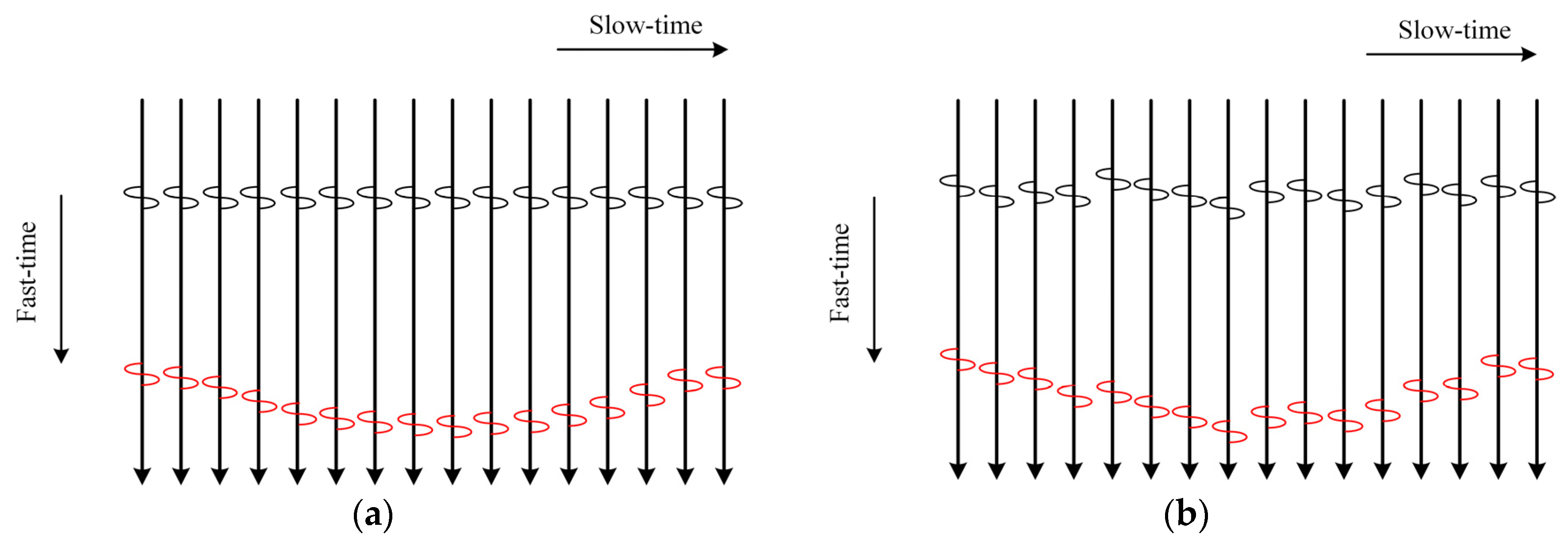
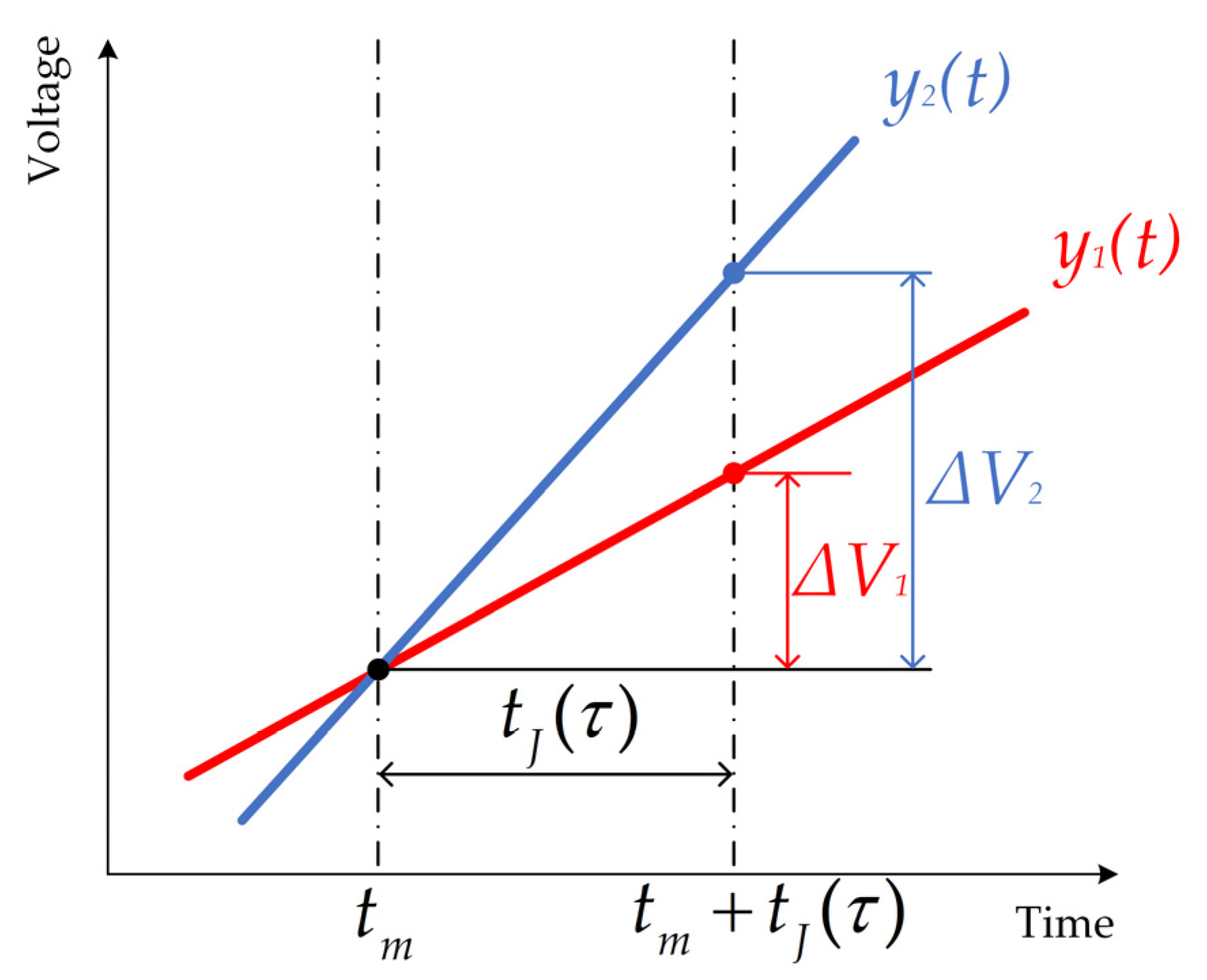
2. Timing Jitter Analysis

The Gaussian pulse emitted by the UWB impulse radar can be formulated as [42]:
x ( t ) = 1 2 π σ t e ( t 2 2 σ t 2 ) ,
where σ t is related to the pulse width.
Consider a simple situation, and assume that there is only one human target and one stationary target in the detection area. The impulse response of the UWB impulse radar can be expressed as [43]:
h ( t , τ ) = a r δ ( t t r ( τ ) ) + a s δ ( t t s ) ,
where t represents fast-time and τ represents slow-time. a s δ ( t t s ) denotes the response of the static target with propagation time t s and amplitude a s . a r δ ( t t r ( τ ) ) is the respiration response of the human target with propagation time t r ( τ ) and amplitude a r . The propagation time t r ( τ ) varies approximately as harmonic vibration due to respiration [44].
The received signal can be expressed as:
y ( t , τ ) = x ( t ) h ( t , τ ) = a r x ( t t r ( τ ) ) + a s x ( t t s )     = r ( t , τ ) + c ( t ) .
The human respiration signal is r ( t , τ ) , and c ( t ) represents the stationary target clutter which is considered constant in slow-time.
However, in a real radar system, the time interval between successive pulses emitted varies randomly and cannot be guaranteed to be ideally fixed. Due to the timing jitter, t J ( τ ) , the actual transmitted signal x J ( t , τ ) can be formulated as [45]:
x J ( t , τ ) = x ( t + t J ( τ ) ) .
Correspondingly, the received signal, y J ( t , τ ) , can be formulated as:
y J ( t , τ ) = x J ( t , τ ) h ( t , τ ) = a r x ( t t r ( τ ) + t J ( τ ) ) + a s x ( t t s + t J ( τ ) )     = r J ( t , τ ) + c J ( t , τ ) .
It is worth noting that the stationary target clutter, c J ( t , τ ) , becomes variable with slow-time, τ , due to timing jitter. Impulse responses recorded by the UWB radar for this scenario are shown in Figure 1, where the vertical axis represents the fast-time dimension of the impulse response and the horizontal axis represents the slow-time dimension. One vertical line indicates one impulse response. Waves scattered from the stationary target are illustrated by the black bipolar monopulse and waves scattered from the human target are depicted by the red bipolar monopulse. In the ideal absence of timing jitter, the clutter scattered by the stationary target creates a horizontal line parallel to the slow-time axis, which can be regarded as a time-invariant background. When timing jitter is present, impulse responses are not aligned to each other, and the time-invariant horizontal line no longer exists. As a result, the position where clutter appears in each impulse response will be random, and the clutter, like the human respiratory signal, will be related to slow-time.
Furthermore, expanding c J ( t , τ ) in Equation (5) using Taylor series around t m , and ignoring the high-order items, c J ( t , τ ) can be approximated as [46]:
c J ( t m , τ ) = a s x ( t m t s + t J ( τ ) ) a s ( x ( t m t s ) + x ( t t s ) t t = t m t J ( τ ) ) .
We denote the first-order derivative of x ( t t s ) by k ( t ) = x ( t t s ) / t , then c J ( t , τ ) can be expressed in discrete form as:
c J [ m , n ] = a s [ x ( m δ T t s ) + k ( m δ T ) t J ( n T s ) ] ,
where m = 0 , 1 , , M 1 is the fast-time sampling point and n = 0 , 1 , , N 1 is the slow-time sampling point. δ T is the fast-time sampling interval and T s is the pulse repetition time, which is also the slow-time sampling interval.
In general, timing jitter, t J ( τ ) , obeys a Gaussian random process with mean zero and standard deviation σ J [47], as:
t J ( τ ) N ( 0 , σ J 2 ) .
Thus, c J [ m , n ] also obeys the Gaussian random process in the slow-time dimension, which can be expressed as:
c J [ m , n ] N ( a s x ( m δ T t s ) , a s k ( m δ T ) 2 σ J 2 ) .
c J [ m , n ] has mean a s x ( m δ T t s ) and variation a s k ( m δ T ) 2 σ J 2 . It can be obtained that the distortion introduced by timing jitter depends on the change rate of the signal and the jitter level.
The distortion caused by timing jitter is schematically shown in Figure 2. The two solid lines indicate the sloped part of received signals y 1 ( t ) and y 2 ( t ) , with different slopes. The signals are assumed to be recorded at t m . However, due to the timing jitter, t J ( τ ) , they are recorded at t m + t J ( τ ) . In this example, for the signals y 1 ( t ) and y 2 ( t ) , the distortions it causes are Δ V 1 and Δ V 2 , respectively.
The same conclusion can be obtained that the distortion introduced by timing jitter depends on the slope of the signal and the level of timing jitter. Since UWB impulse radar transmits pulses that are narrow in time, this results in a large change rate of the transmitted signal. At the same time, to improve the SCNR, increasing the transmitted power of the radar is a simple and effective method. This in turn makes the change rate of the transmitted signal and jitter level further increase, worsening the distortion. In the frequency domain, the distortion occupies the entire frequency band and is quite large in the human respiration region. Therefore, it is difficult to perform human respiration signal extraction in the frequency domain without distortion suppression.

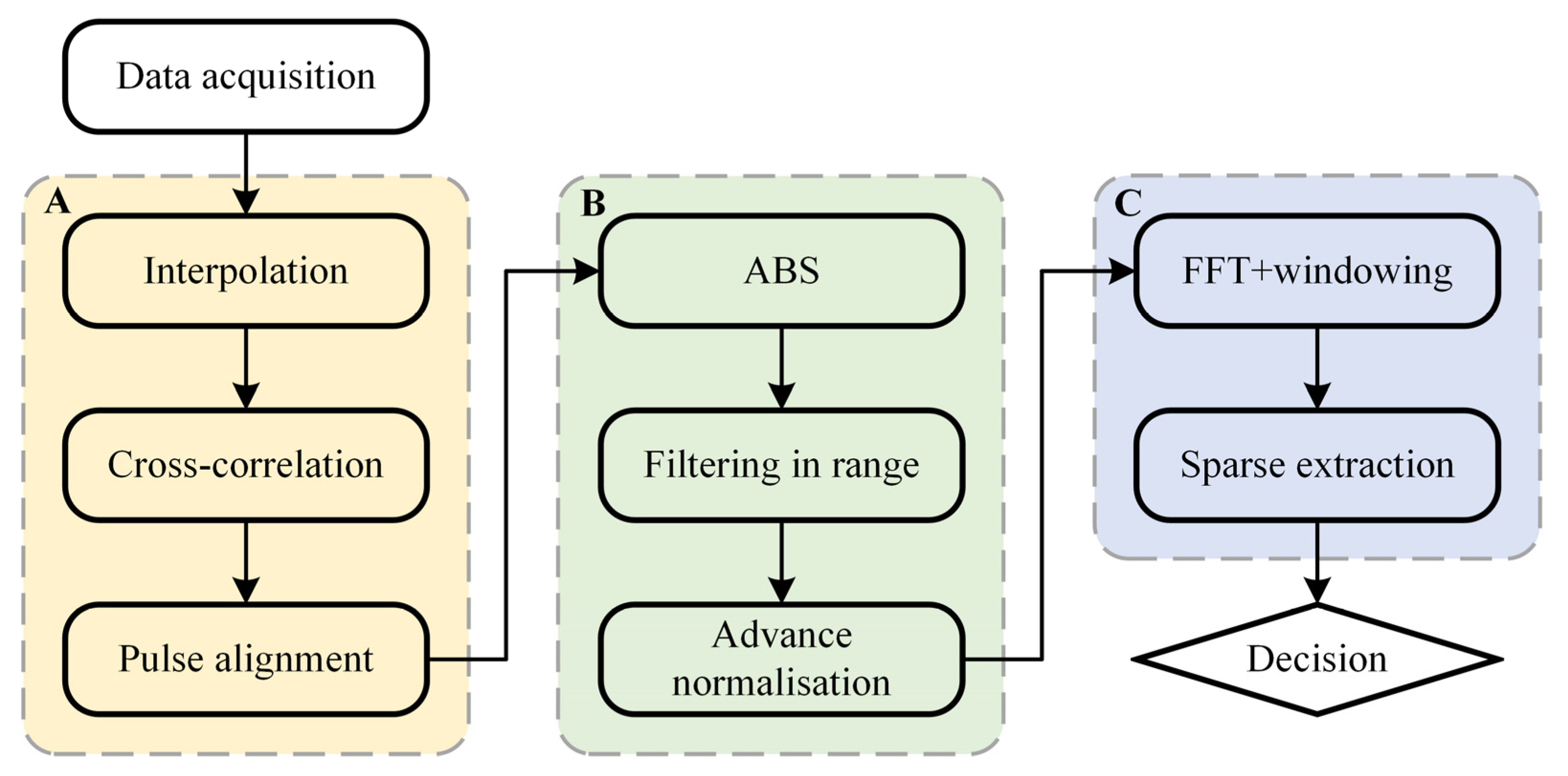
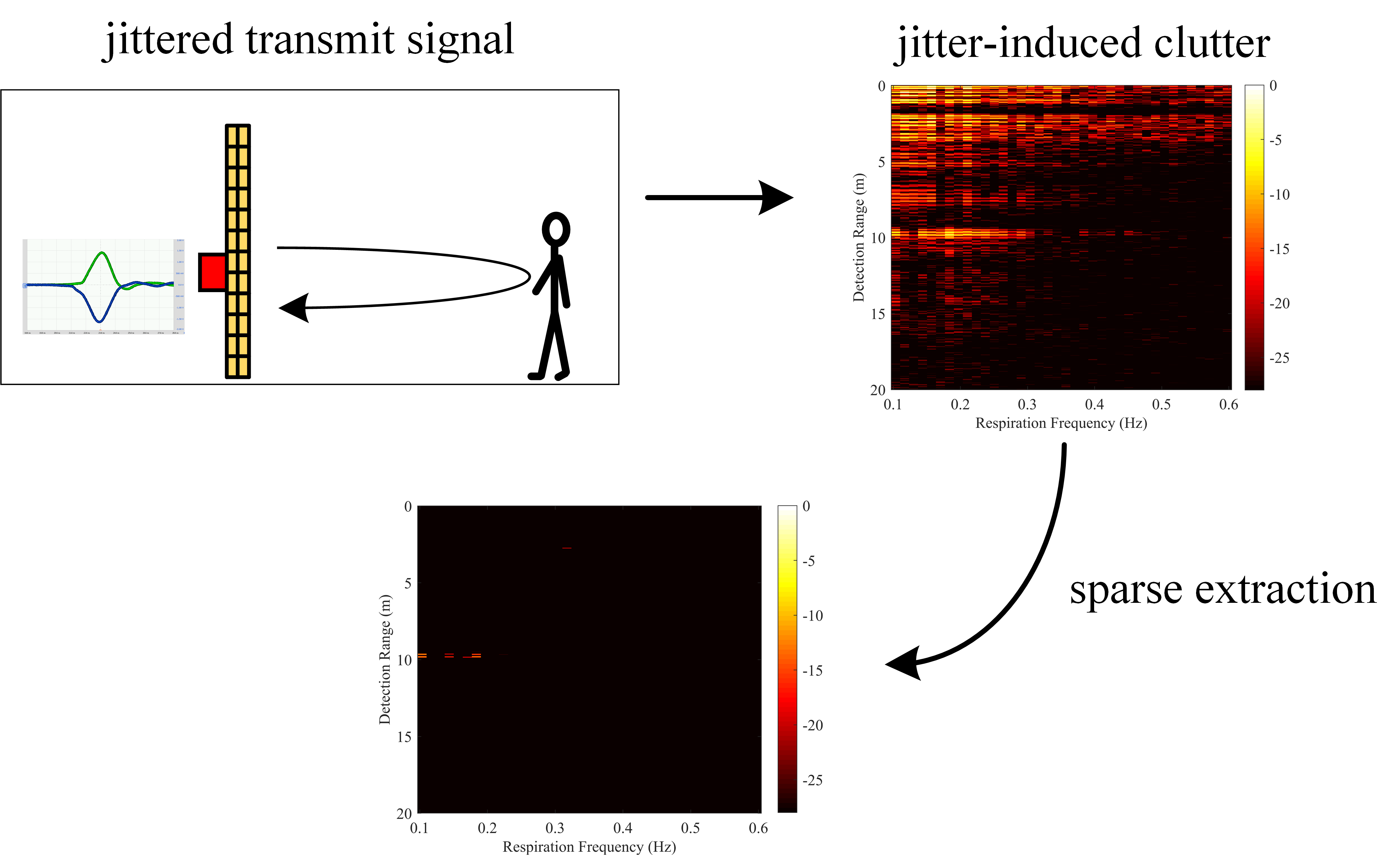
3. Proposed Method for Reducing Timing Jitter’s Impact in Through-Wall Human Detection

From the above analysis, it can be obtained that timing jitter can turn the clutter scattered from stationary targets into dynamic interference. Inspired by the recent studies in low-rank approximations, we model the range-frequency matrix in the frequency domain as a superposition of the low-rank representation of jitter-induced clutter data and the sparse representation of human respiratory data. The problem of suppressing non-stationary clutter introduced by timing jitter in human respiration detection can be converted into an optimization problem of low-rank and sparse representation. In this section, we propose a method to effectively reduce the effect of timing jitter. The flowchart of the proposed method is illustrated in Figure 3. The proposed method consists of three main steps: (A) initial compensation method in the time domain, (B) signal enhancement method, and (C) sparse component extraction method in the frequency domain. First, in step A, we use cross-correlation to correct the time offset of each impulse response, achieving initial compensation for timing jitter in the time domain. Then, in step B, we suppress background and noise signals, and enhance weak respiration signals to improve SCNR. Finally, in step C, the difference of sparsity in the frequency dimension between the human respiration signal and the jitter-induced clutter is used to accurately extract the human respiration signal in the frequency domain.

3.1. Step A: Initial Compensation Method in the Time Domain

To achieve initial compensation for timing jitter, a simple idea is to find the time offset of each impulse response and then compensate it to the correct time instant. Since the timing jitter interval is often shorter than the fast time sampling interval, interpolation is performed first to fill the gap between the two fast time sampling points. Next, we find the time offset between the two impulse responses by cross-correlation in the time domain and then align each impulse response, thus achieving initial compensation for timing jitter. Considering the computing time, we only perform the cross-correlation operation on the direct wave part of the impulse response. We choose one impulse response as a reference and denote it by y r [ m ] . y n [ m ] denotes the nth impulse response. Then, the cross-correlation function between the nth impulse response y n [ m ] and the reference response y r [ m ] can be defined as:
x c o r r n [ m ' ] = E { y n [ m 1 ] y r [ m 2 ] } ,
where 0 m 1 , m 2 M , and m ' = m 1 m 2 .
The peak position of the cross-correlation function indicates the time offset of the two impulse responses,
Δ m n = arg max m ' ( x c o r r n [ m ' ] ) .
Correspondingly, the nth impulse response is shifted by Δ m n in the fast-time dimension so that it is aligned with the reference impulse response,
y n _ a l i g n e d [ m ] = y n [ m + Δ m n ] .
Align each impulse response with the reference impulse response to achieve initial compensation for timing jitter in the time domain.

3.2. Step B: Signal Enhancement Method

3.2.1. Adaptive Background Subtraction

The strong time-invariant background usually covers the respiration signal of interest, so the background needs to be removed from the received data. The simplest method is to calculate an average impulse response from all measured impulse responses. However, this method can only be processed after the measurement is completed and cannot be operated in real time. When detecting people based on their micro-movement, respiration or cardiac activity, these reflected signals have the same time delay and are easily misinterpreted as static clutter and removed using background subtraction.
Based on the above analysis, we choose the adaptive background subtraction (ABS) method based on the exponential averaging, which replaces a scalar weighting factor α with a vector of weighting coefficient λ [48].
p n [ m ] = λ n [ m ] × p n 1 [ m ] + ( 1 λ n [ m ] ) × q n [ m ] ,
where p n [ m ] and q n [ m ] are one-dimensional vectors with the size [M × 1] and contain ‘sampled background estimate’ and ‘measured impulse response’, respectively. Thus, the new background estimate takes a fraction of the previous estimate and a fraction from the measured impulse response. The weighting coefficient has the size [M × 1] and is determined by two thresholds related to motions, and motions are automatically divided into micro- and macro-motions.

3.2.2. Filtering in Fast-Time Dimension

In order to further improve SCNR, a bandpass filter with the same bandwidth as the transmitted signal is added and performed along the fast-time dimension to filter out substantial high-frequency noise introduced by oversampling.

3.2.3. Advance Normalization

It follows from the basic radar equation that the level of signal components scattered by a target and received by the radar depends among others on the distance between transmitting antenna-target-receiving antenna. In addition, the low reflectivity of human body and high signal attenuation of obstacles make the energy of the respiration signal recorded by the radar weak.
The advance normalization (AN) method is used to enhance the weak respiration signal [49]. The basic idea of the method is to search the maximum in the interval ( t L max , t e n d ] serially, and normalize the current signal in the interval ( t L max , t N max ] , where t L max represents the propagation time instant of the last found maximum, t N max is the propagation time instant of the new found maximum, and t e n d is the last time instant of the measured impulse response.

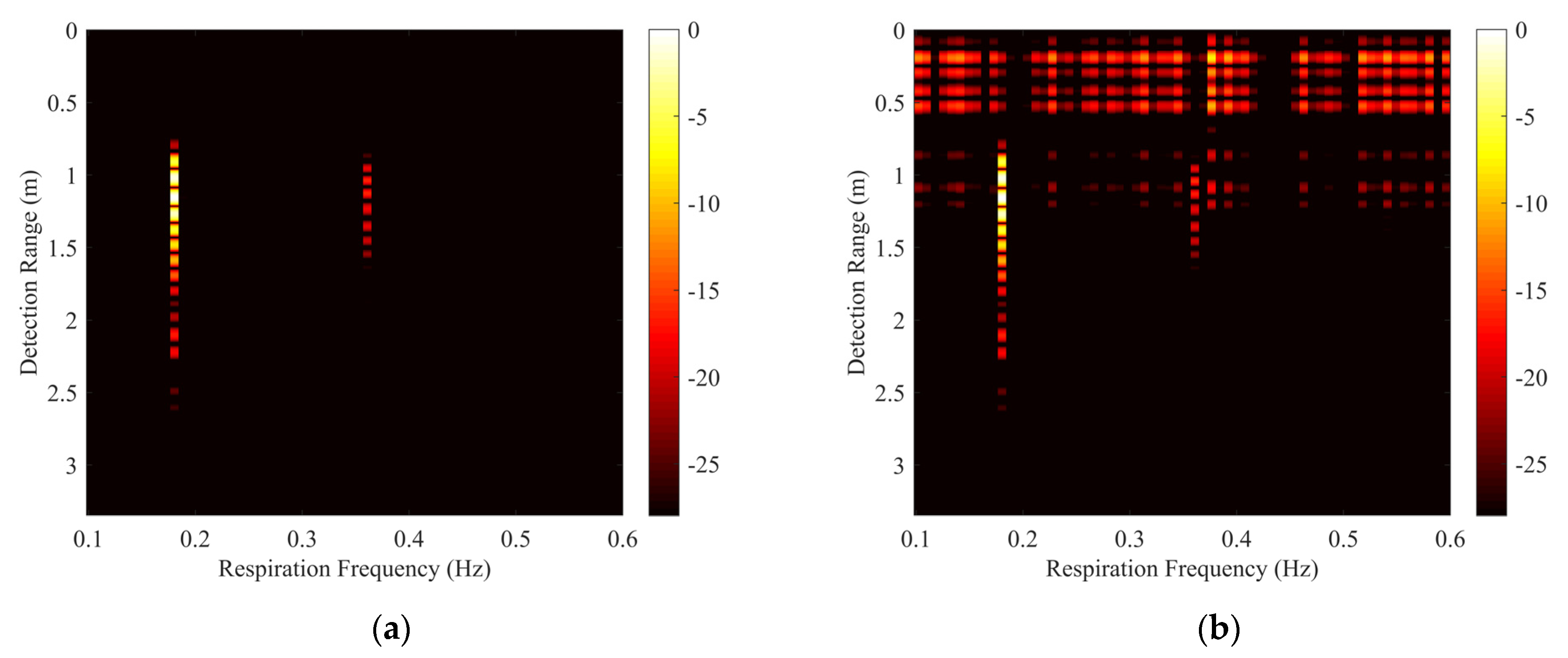
3.3. Step C: Sparse Component Extraction Method in the Frequency Domain

To extract the frequency of the respiration signal, the Fast Fourier transform (FFT) is performed in the slow-time dimension. Based on the prior knowledge of human respiration frequency, a selected frequency window ranging from 0.1 to 0.6 Hz is added to remove high-frequency components. Its resultant matrix is M × N w range-frequency matrix Y, where N w represents the number of frequency points after windowing.
In an ideal situation without timing jitter, the matrix Y will only include respiration signal:
Y = Y r e s p i r a t i o n .
With timing jitter present, not only respiration signals but also non-stationary clutter will exist in the matrix Y. The non-stationary clutter induced by timing jitter occupies the entire frequency band, and in the range-frequency matrix, it can be considered as a low-rank component. The respiration signal exhibits concentrated characteristics in both range and frequency dimensions, and it can be regarded as a sparse component relative to the whole range-frequency matrix. We model the range-frequency matrix Y as a superposition of the low-rank representation of jitter-induced clutter data and the sparse representation of human respiratory data:
Y = Y r e s p i r a t i o n + Y c l u t t e r .
Using the difference in the sparsity of the two signals in the frequency dimension, we can separate them well in the frequency domain. Low-rank and sparse representation recovers a low-rank matrix L and a sparse matrix S from a data matrix Y (Y = L + S) through the following process:
min L , S   r a n k ( L ) + λ S 0 s . t . Y = L + S .
However, Equation (16) is a highly nonconvex optimization problem with no efficient solutions. To make it become a tractable optimization problem, many methods have been presented in the literature. Robust principal component analysis (RPCA) [50] optimizes the objective function by replacing the l 0 -norm with the l 1 -norm, and the rank of L with the nuclear norm L :
min L , S   L + λ S 1 s . t . Y = L + S .
Some works have shown that the Frobenius norm based representation is more computationally efficient than nuclear norm based representation [51,52]. The objective function proposed by principal coefficients embedding (PCE) [53] is as follows:
min C , L , S   1 2 C F 2 + λ 2 S 1 2 s . t . Y = L + S , L = L C .
Robust non-negative matrix factorization (RNMF) is a novel dimensionality reduction method based on matrix factorization that can separate the low-rank and sparse parts of the data in case the data are grossly corrupted [54]. We choose RNMF to extract the sparse component. Y can be expressed as
Y = Y r e s p i r a t i o n + Y c l u t t e r S + W H .
where Y M × N w , W + M × k , H + k × N w , S M × N w , and k is the rank. The sparse respiration signal is approximated by the sparse error matrix S:
Y r e s p i r a t i o n S .
The low-rank non-stationary clutter is approximated by the product of two non-negative matrices W and H:
Y c l u t t e r W H .
We chose the square Euclidean distance between Y and S + W H to measure the approximation error in Equation (19), and added a l 1 -norm constraint on S to enhance the sparsity. Thus, Equation (19) can be formulated as an optimization problem:
min W , H , S Y W H S F 2 + λ S 1 s . t . W i j 0   and   H i j 0   for   each   i   and   j ,
where   ·   F denotes the matrix Frobenius norm, S 1 = i = 1 m j = 1 n S i j , and λ > 0 . λ is the regularization parameter, which determines the sparsity of S.
Problem (22) is separately convex for W, H, and S, so a local optimal solution can be obtained by solving a series of convex optimization problems. The values of W, H, and S are updated separately when other variables are fixed. For W and H, the optimization problems are in the form of non-negative quadratic programming, which can be solved by multiplicative updates [55].
Consider a non-negative quadratic programming problem of the following form:
min v   1 2 v T A v + b T v s . t . v i 0 ,   for   each   i ,
where A is a symmetric positive semidefinite matrix. It has been proven that the optimal solution of problem (23) can be obtained by multiplicative updates [55]:
v i b i + b i 2 + 4 ( A + v ) i ( A v ) i 2 ( A + v ) i v i .
Both A + and A represent non-negative matrices, and they are defined as follows:
A i j + = A i j ,   if   A i j 0 , 0 ,   else , A i j = A i j ,   if   A i j < 0 , 0 ,   else .
With each iteration of Equation (24), the value of the objective function will decrease.
Consider the update of H, when W and S are fixed. Y W H S F 2 of Equation (22) can be expressed as:
Y W H S F 2 = S Y + W H F 2 = trace ( S Y ) T + H T W T ( S Y + W H ) = trace ( H T W T W H ) + 2 trace ( ( S Y ) T W H ) + trace ( ( S Y ) T ( S Y ) ) .
In this way, the convex optimization problem for updating H can be expressed as:
min H   trace ( H T W T W H ) + 2 trace ( ( S Y ) T W H ) s . t . H i j 0   for   each   i   and   j .
Problem (27) can be solved using Equations (23) and (24). W T W in Equation (27) corresponds to the matrix A in problem (23). Since W is a non-negative matrix, we can obtain:
A + = A = W T W , A = 0.
The iterative update equation for H is as follows:
H i j ( W T ( S Y ) ) i j ( W T ( S Y ) ) i j 2 ( W T W H ) i j H i j .
Similarly, the update rule for W is given by:
W i j ( ( S Y ) H T ) i j ( ( S Y ) H T ) i j 2 ( W H H T ) i j W i j .
In order to ensure that the solution to the optimization problem is unique, each basis vector in W is normalized and the norms of the bases are compensated to H. Two normalization steps can be given as
W i j W i j i = 1 M W i j 2 ,
H i j H i j i = 1 M W i j 2 .
For S, the optimization problem can be solved by the soft-thresholding operator [56]. The definition of the soft-thresholding operator, T v ( · ) , is as follows:
T v ( x ) = x v ,   if   x > v , x + v ,   if   x < v , 0 ,   else ,
where x and v > 0 . Consider a l 1 -minimization problem of the following form:
min b   1 2 x b F 2 + v b 1 .
The solution b of Equation (34) can be given by T v ( x ) [56]. When W and H are fixed, the optimization problem for updating S is:
min S   Y W H S F 2 + λ S 1 .
Thus, the optimal solution to problem (35) is T λ / 2 ( Y - W H ) . The iterative update equation for the matrix S can be formulated as:
S Y W H ,
S i j S i j λ / 2 ,   if   S i j > λ / 2 , S i j + λ / 2 ,   if   S i j < λ / 2 , 0 ,   else .
Equation (37) shows that if ( λ / 2 ) > m a x i j ( Y W H ) i j , S will become a null matrix. It should be noted that, for RNMF, the regularization parameter λ is a key parameter that controls the trade-off between the low-rank component and the sparse component. When the value of λ is too large, the matrix S represents little sparse information and corrupts the respiration signal of interest. When the value of λ is too small, the matrix S contains clutter and noise, increasing the difficulty of respiration extraction. In our method, we carefully chose the value of λ that maximizes the SCNR for the UWB impulse radar prototype used and applied the same value in all experiments.

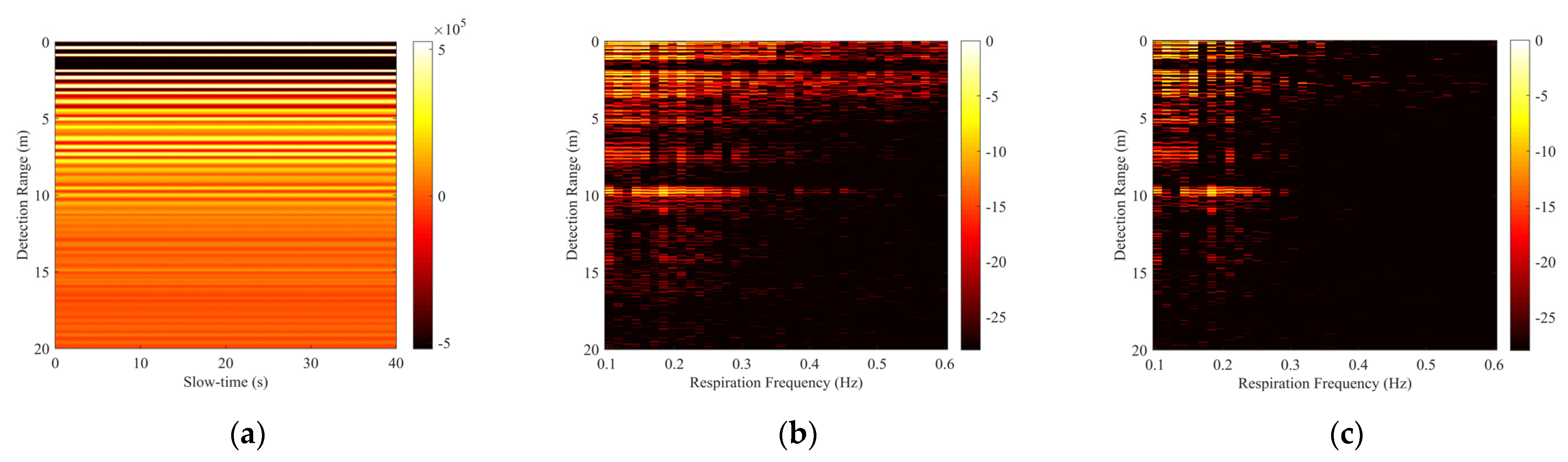
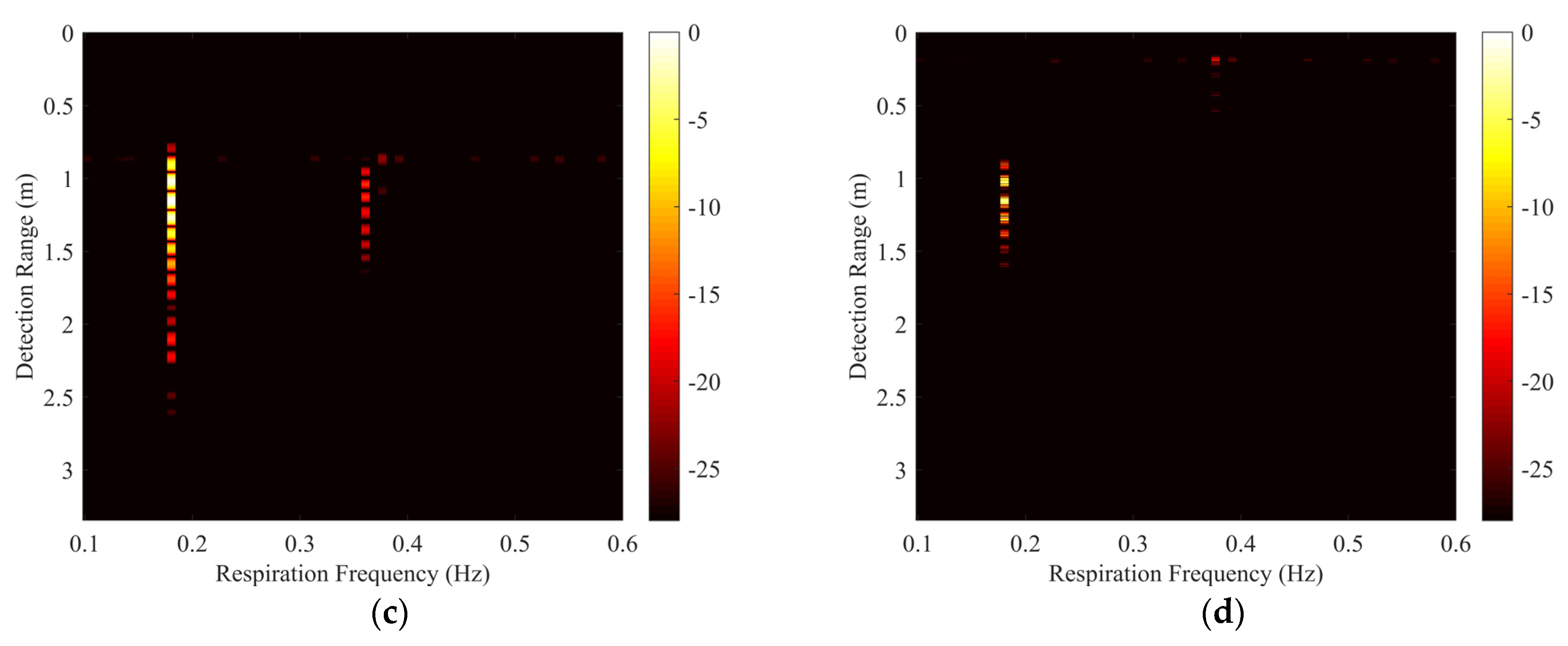
4. Numerical Simulation

Numerical simulation of a realistic through-floors respiration detection scenario has been performed using the gprMax software to validate the effectiveness of the proposed algorithm. Two floors are included in the simulation scenario, as shown in Figure 4. The floor is homogeneous and made up of a material with a relative dielectric constant of 4 and a conductivity of 0.01 S/m, and its thickness is 12 cm. The spacing between the two floors is 80 cm. We used a metal cylinder whose radius is modulated by the simple harmonic motion at 0.18 Hz to simulate the chest motion caused by human breathing. The metal cylinder is placed 15 cm above the lower floor. The antenna model was chosen from its inbuilt library as Geophysical Survey Systems, Inc. (GSSI), working at 400 MHz. Since the change of time is equivalent to the change of distance, we simulated the timing jitter of the transmitted signal by randomly varying the height of the antenna model. The distance of the antenna from the upper floor obeys a Gaussian distribution with a mean value of 15 cm and a standard deviation of 3 mm.
The direct FFT results of the raw echo signal without timing jitter and with timing jitter are shown in Figure 5a,b, respectively. From Figure 5a, we can see that the respiration signal with a Doppler frequency of 0.18 Hz and its harmonic component are included in the range-frequency matrix Y. Due to the differential effect of the antenna, the respiration signal exhibits multiple peaks in the range dimension. As can be seen in Figure 5b, in addition to the respiration signal and its harmonic component, clutter scattered by floors is also detected, which should be time-invariant but becomes non-stationary clutter due to timing jitter. The strength of the clutter scattered by the upper floor is higher than that of the clutter scattered by the lower floor. The clutter affects the extraction of the respiration signal. The non-stationary clutter induced by timing jitter occupies the entire frequency band, and in the range-frequency matrix Y, it can be considered as a low-rank component. The respiration signal exhibits concentrated characteristics in both range and frequency dimensions, and it can be regarded as a sparse component relative to the whole range-frequency matrix Y.
The proposed algorithm was compared with MS, SVD, and the method in [36]. Figure 6a–d represents the respiration detection results of MS, SVD, the method in [36], and the proposed algorithm, respectively. Unlike the traditional MS algorithm, we averaged the data in the frequency dimension instead of the slow-time dimension. The MS algorithm can suppress non-stationary clutter, but the suppression is limited and does not completely remove the clutter. The SVD algorithm eliminates the clutter by discarding the eigenvectors corresponding high-valued eigenvalues. The result indicates that the SVD algorithm also retains part of the non-stationary clutter. The method in [36] removes the jitter distortion in clutter mitigation by only aligning impulse responses in the time domain. In its result matrix, the clutter scattered by both floors is well-removed, and the respiration signal and its harmonic component are retained. Our proposed algorithm can suppress the non-stationary clutter scattered by both floors, and only the respiration signal is included in the range-frequency matrix Y. Although the extracted respiration signal is corrupted in the range dimension, its most important part is retained, and this corruption is acceptable.
We used improvement factor (IF) for quantitative analysis, which indicates the improvement of the SCNR after suppressing non-stationary clutter. IF in decibels (dB) is given as:
IF = 10 log 10 ( S C N R a f t e r / S C N R b e f o r e ) ,
where S C N R b e f o r e and S C N R a f t e r are the SCNRs of the result of respiration detection before and after applying the non-stationary clutter suppression method, respectively. The SCNR of the range-frequency matrix is defined as:
S C N R = N C p Y S Y ( p ) 2 N S p Y C Y ( p ) 2 ,
where N S and N C are the number of elements in the selected signal region Y S and clutter region Y C , respectively. Y ( p ) denotes the pth element of the matrix.
Quantitative results of different methods are compared in Table 1. The MS algorithm averaging in the frequency dimension is a little better than SVD. Both the method in [36] and our proposed method have higher scores. Although our proposed method partially corrupted the respiration signal, it still obtained the highest IF score of 13.45 dB.

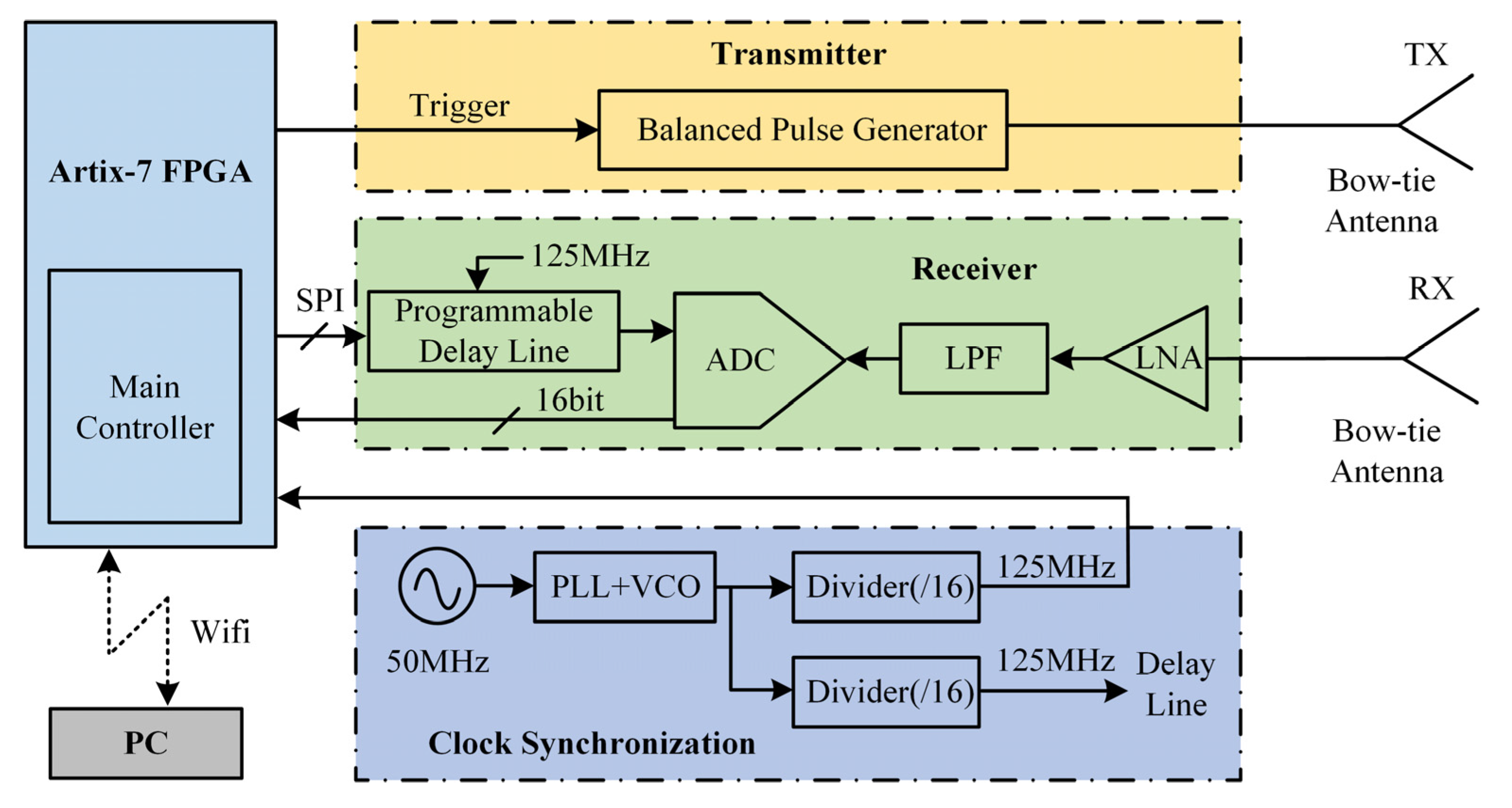
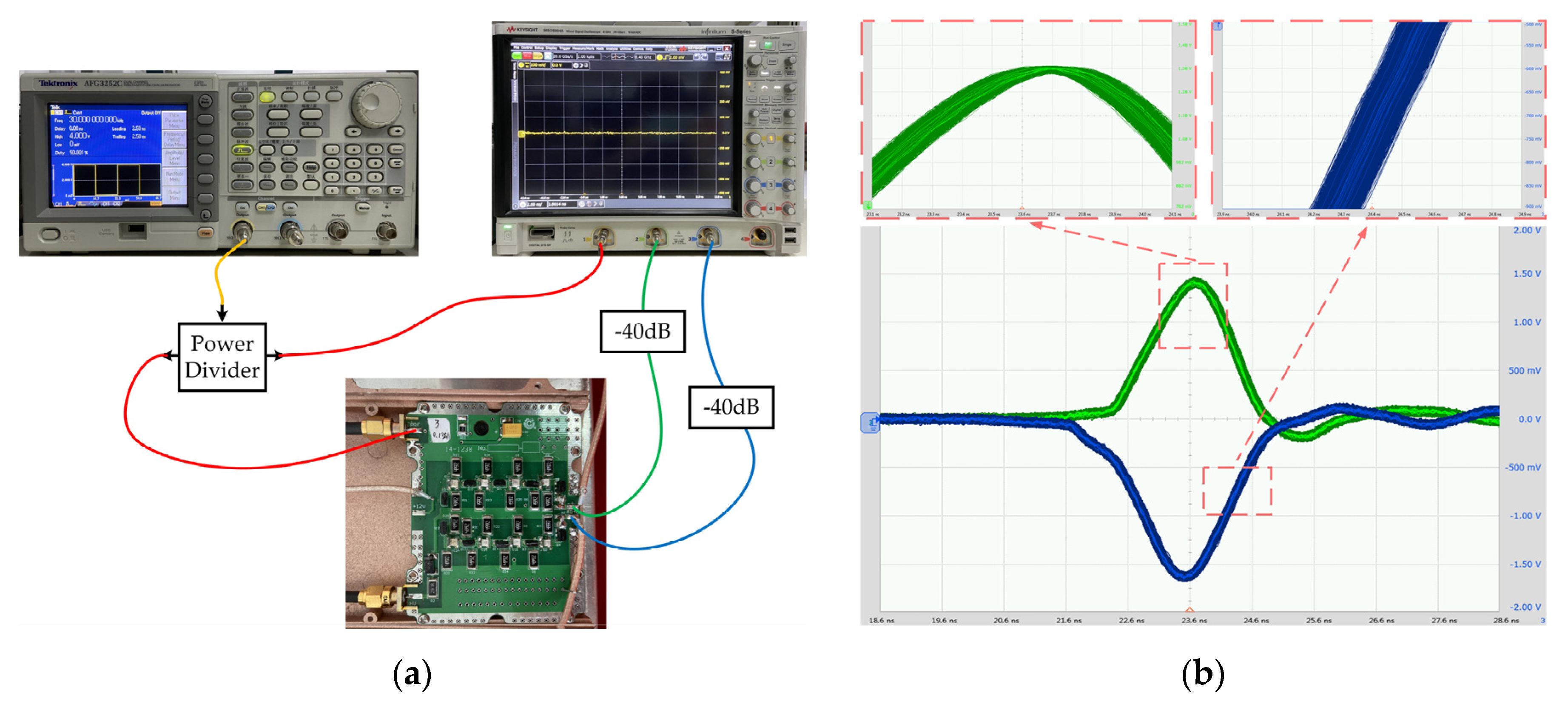
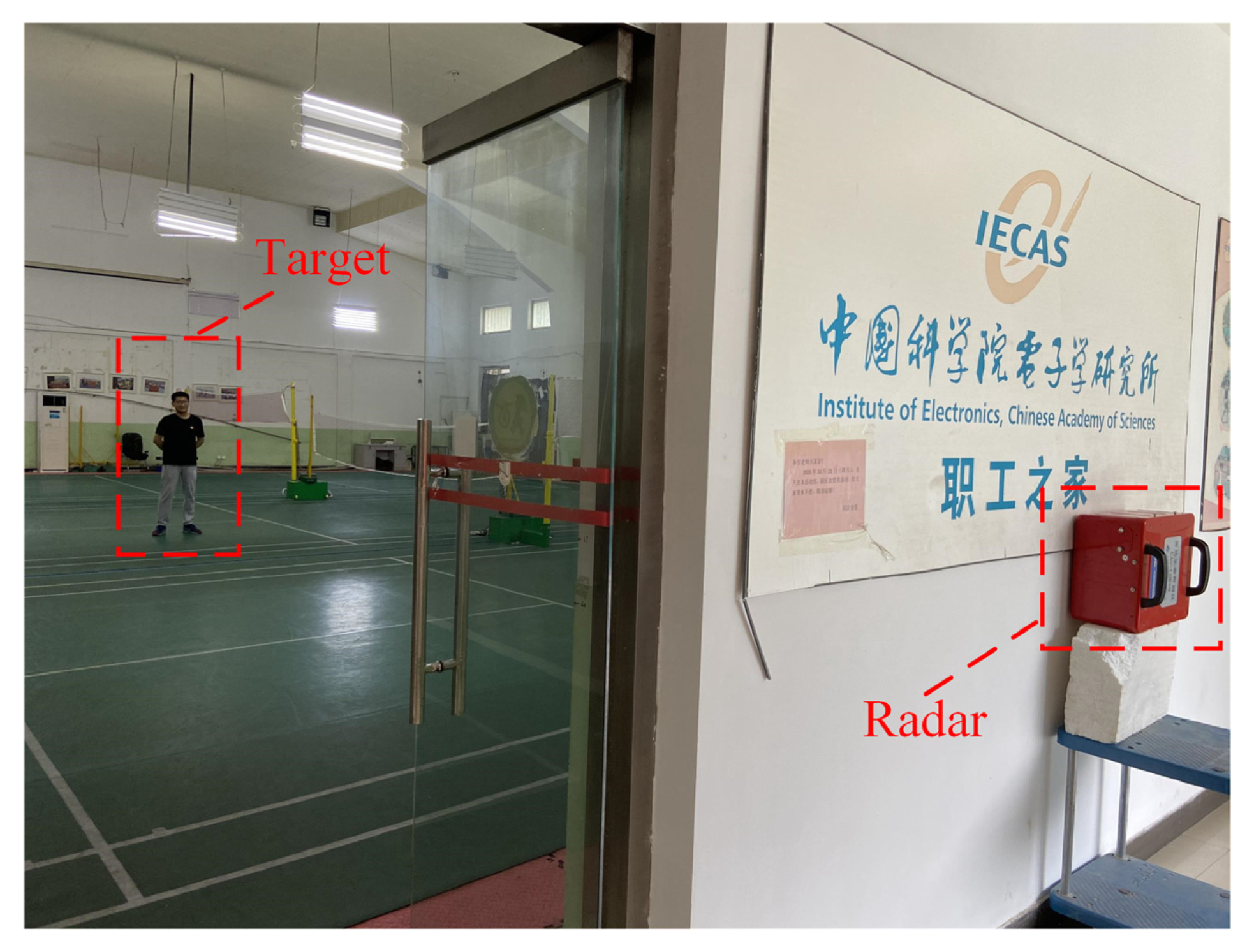
5. Experimental Verification of The Proposed Method

To validate the effectiveness of the proposed method in realistic scenarios, we used the UWB impulse radar prototype developed by ourselves to perform a series of experiments at the Aerospace Information Research Institute, Chinese Academy of Sciences.

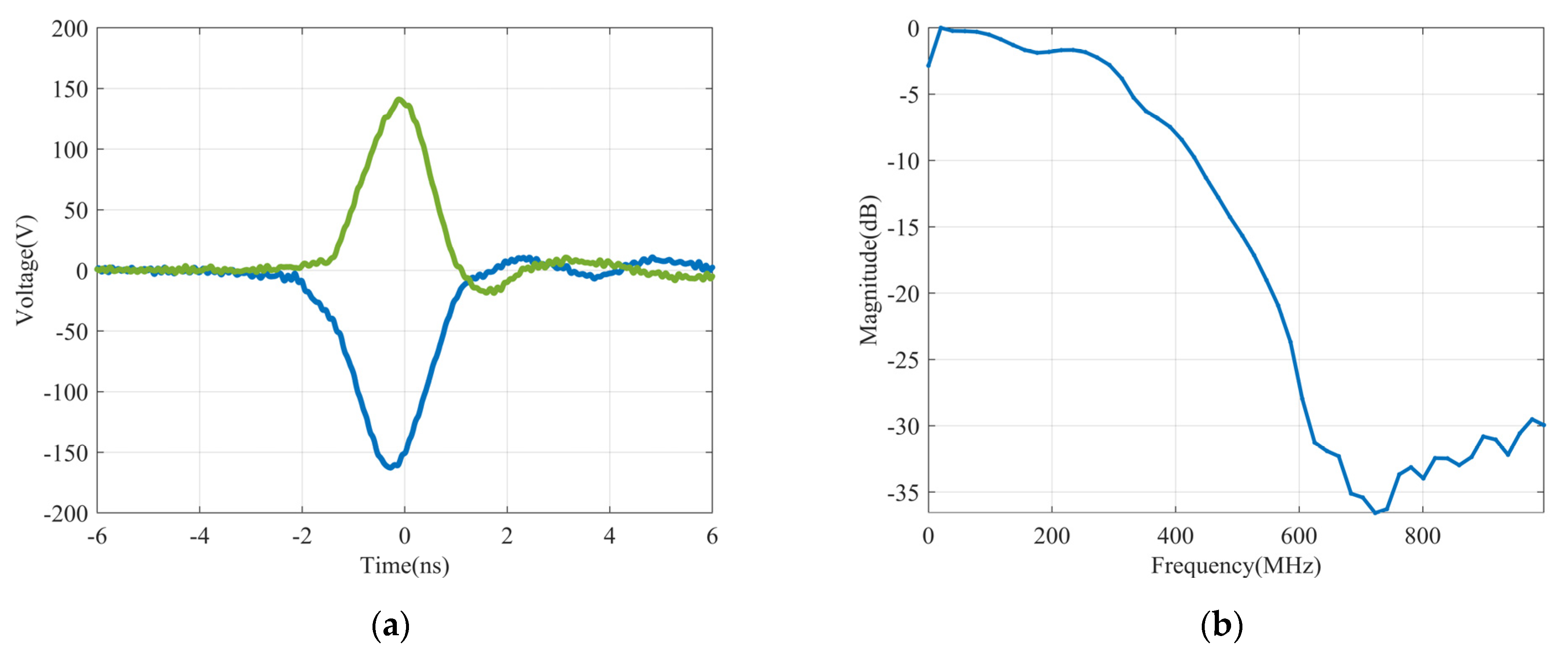
5.1. Experiment Radar System

The UWB impulse radar used consists of a pair of bow-tie antennas, a balanced pulse generator, a receiver, and a clock synchronization module, as shown in Figure 7. The balanced pulse generator is based on the avalanche transistor and Marx Bank. Marx Bank is a commonly used method of generating high-voltage impulses, whose main idea is to charge a number of capacitors in parallel and then discharge them in series. Additionally, a Xilinx Artix-7 Field Programmable Gate Array (FPGA) was used to control the entire system and provide trigger signals to the transmitter, ensuring the synchronization of the whole system by locking these signals to the common clock. At the receiver, the signal from the antenna is fed into the low noise amplifier (LNA), and the output is recorded by a 16-bit analog to digital converter (ADC) with a maximal sampling rate of 160 Mbps and a full-power bandwidth of 1.4 GHz. To reduce the system cost and improve the spurious-free dynamic range (SFDR), the equivalent-time sampling technique was adopted. One Micrel’s SY89297U programmable delay line, which can achieve a maximal delay of 5 ns with 5 ps fine increments, was used to provide a fine delay to the ADC sampling clock. A pair of folded bow-tie antennas were used for electromagnetic radiation and reception, whose basic geometry is combined by a novel acorn-shaped bent bow-tie patch and a hollowed stepped back cavity [57]. The key parameters of the UWB impulse radar used are shown in Table 2.
The output balanced pulses of the transmitter are showed in Figure 8a. The peak amplitudes of these pulses are −162 and +141 V at 50 Ω load, respectively. The power spectrum of the pulse calculated using the Fourier transform is shown in Figure 8b, normalized to the peak value. The −10 dB pulse bandwidth is 433 MHz. The timing jitter was measured using the bench shown in Figure 9a. It includes the mixed signal oscilloscope (MSO) Keysight MSOS804A (with 8 GHz bandwidth and 20 GSa/s sampling rate), the arbitrary function generator (AFG) AFG3252C from Tektronix, and a power divider. The AFG generates a periodic square signal of 32 KHz to be used as the trigger signal. The trigger signal is fed into the power divider and is split into two signals. One is used to trigger the pulse generator and the other is used to trigger the oscilloscope. The pulse generator outputs are connected to the oscilloscope after 40 dB attenuation. The jitter measurement plots for the pulses are shown in Figure 9b. Due to the large amplitude of these pulses, they inevitably have a high level of timing jitter at the same time. During the 30 min observation period, the maximum time base offset was 170 ps.

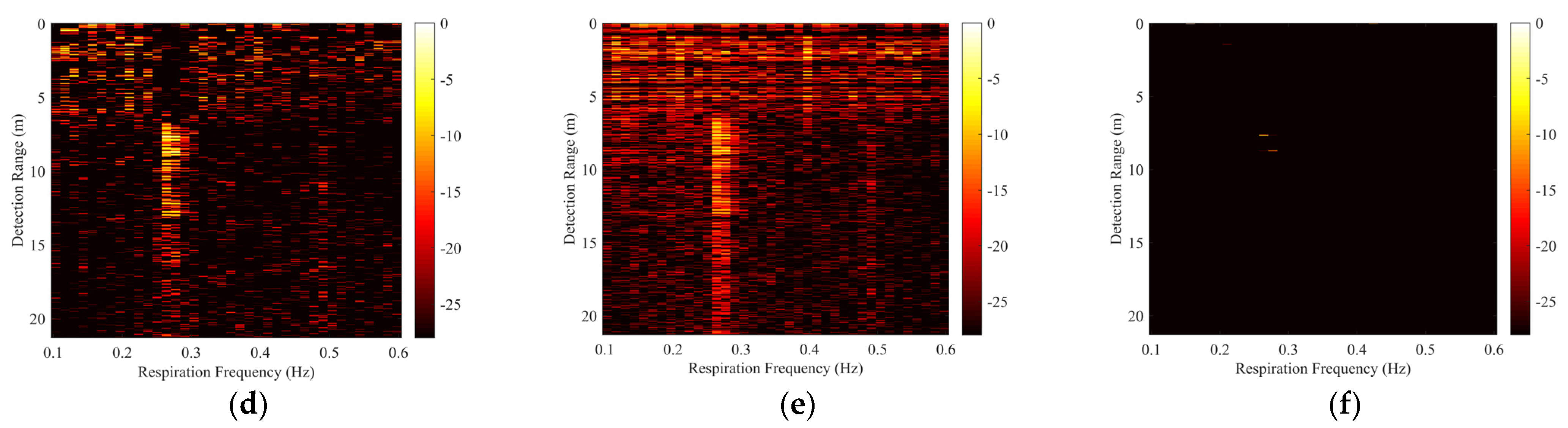
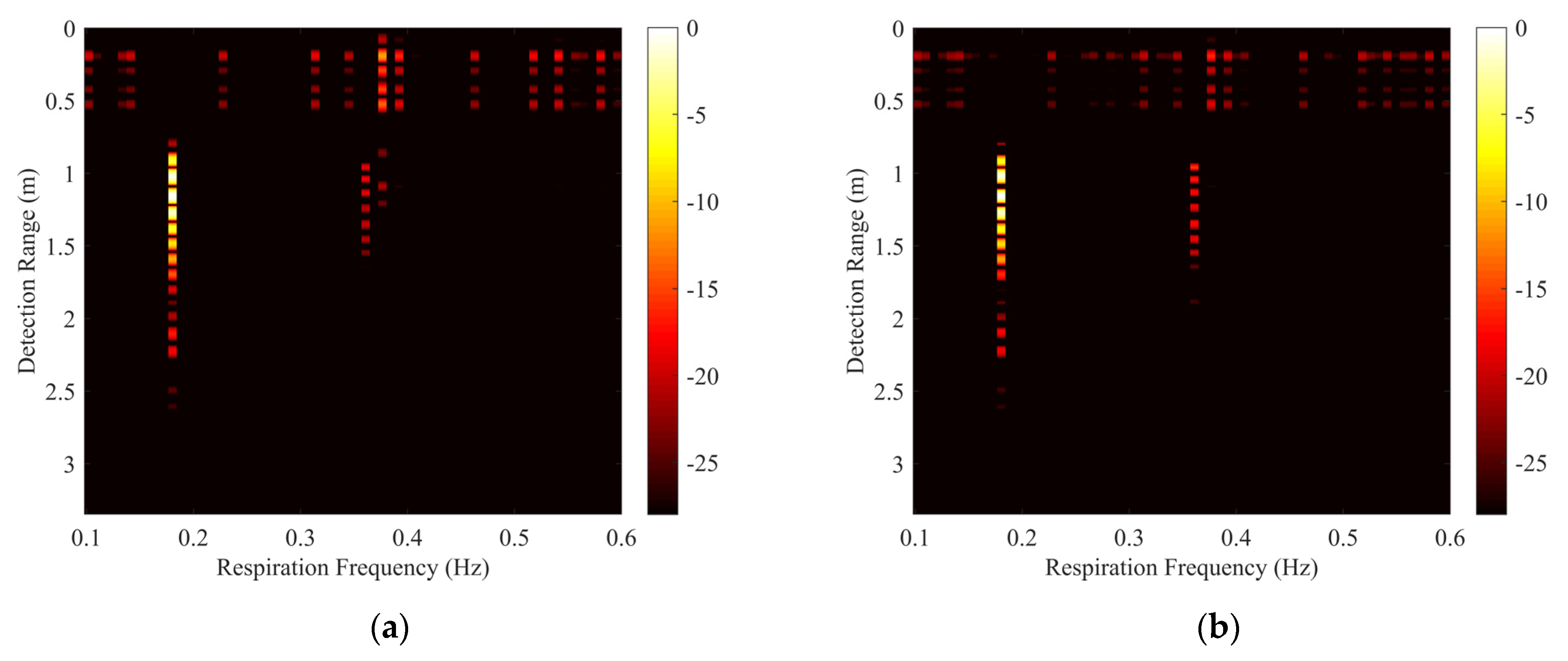
5.2. Detection Performance in Through-Wall Situation

The experiment scenario for through-wall detection is shown in Figure 10. One stationary human target is breathing steadily at 10 m from a brick wall. The thickness of the wall is 40 cm. The UWB impulse radar is placed on the other side of the wall for respiration signal detection.
Figure 11a shows the two-dimensional raw echo matrix. The vital sign signals are masked by a large amount of strong clutter and cannot be extracted directly. The range-frequency matrix Y of the received radar signal after the conventional FFT in slow-time is shown in Figure 11b. The respiration signal at 10 m becomes obvious, but there is also very strong non-stationary clutter induced by timing jitter at other distances. The respiration signal of the tested human is difficult to distinguish by automatic detection algorithms. The results processed by MS, SVD, and the method in [36] are shown in Figure 11c–e, respectively. After being processed by MS, the non-stationary clutter from the wall scattering is partially suppressed, but it is still difficult to extract the respiration signal. After being processed by SVD, the non-stationary clutter is also partially attenuated, but the remaining clutter around the respiration signal is still apparent. Different from the good performance in the simulated data, the method in [36] has very limited suppression of clutter in real data. It shows that the time offset of each impulse response is not fixed in a realistic detection scenario. There are two reasons for this result. One is that we have adopted the equivalent-time sampling technique in our developed radar system, which obtains an impulse response through multiple impulse responses, and the other is the presence of noise in the environment. The result obtained by our proposed algorithm is shown in Figure 11f. When λ is set to 0.3, the non-stationary clutter is effectively eliminated, and the human target can be easily extracted. Figure 11f shows that the range of the target is 10 m, which is consistent with the actual situation.
Table 3 lists the SCNR and IF values of the above methods. Compared with the proposed method, the performance of MS, SVD, and the method in [36] is not effective, because the IF score of the proposed non-stationary clutter suppression method is much higher than other methods. After being processed by the proposed method, the SCNR was improved by more than 20 dB.

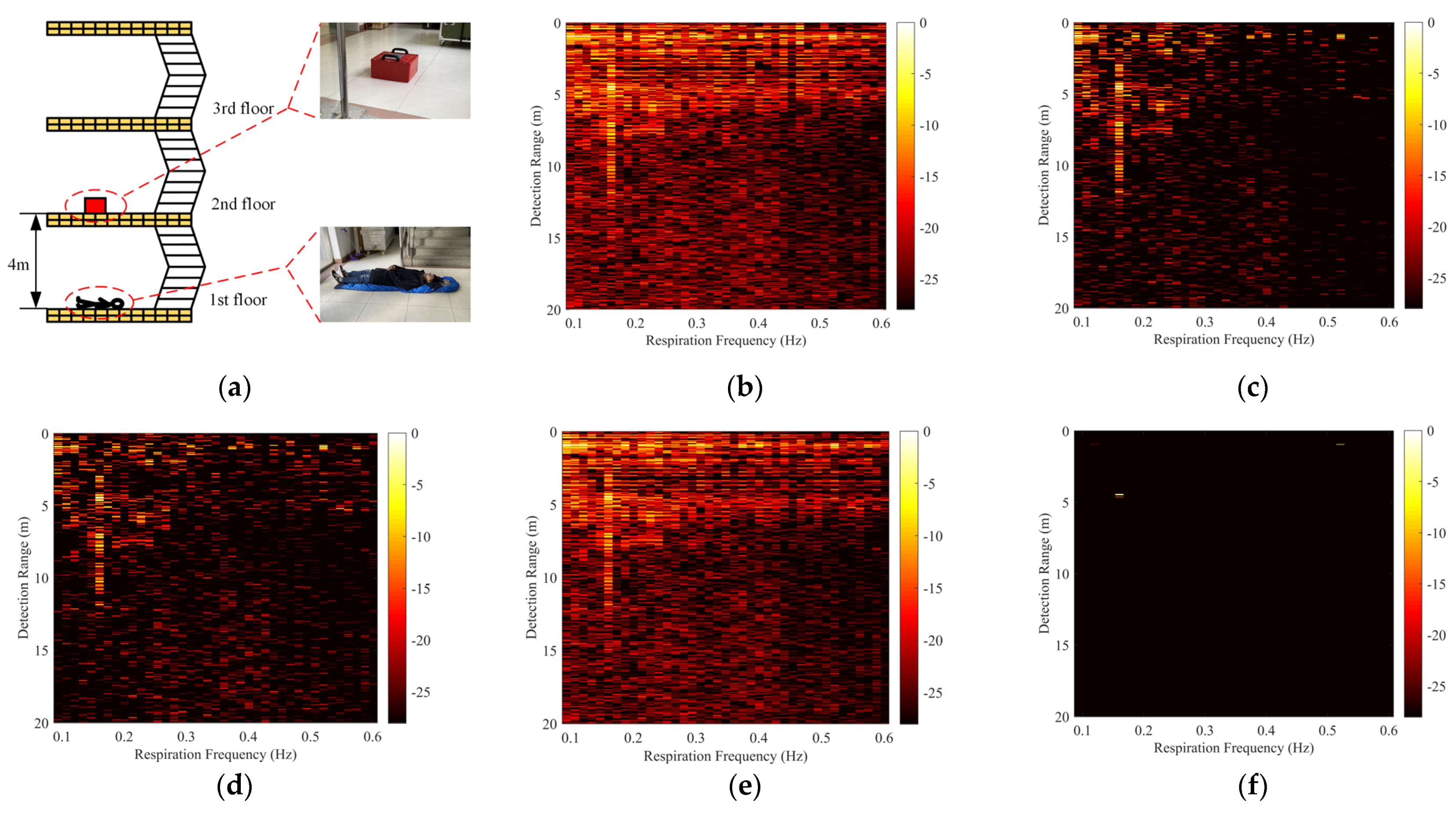
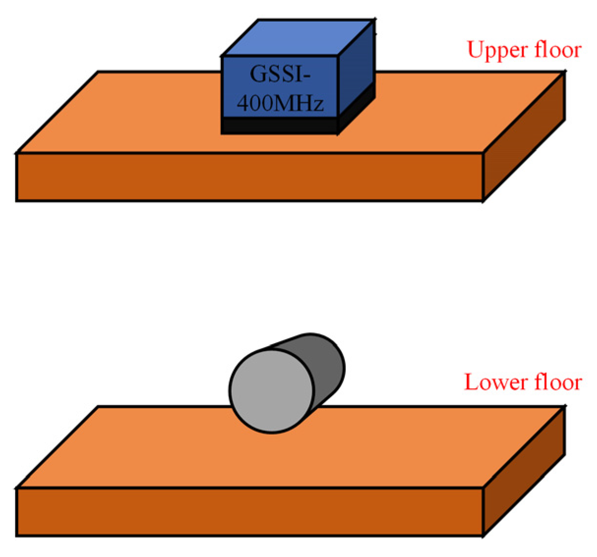
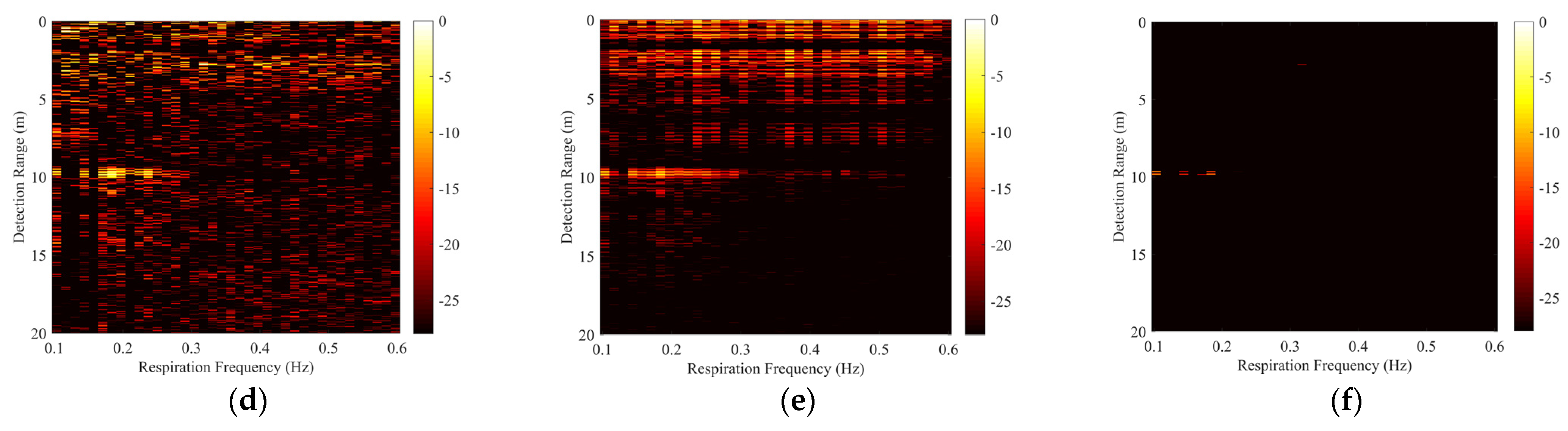
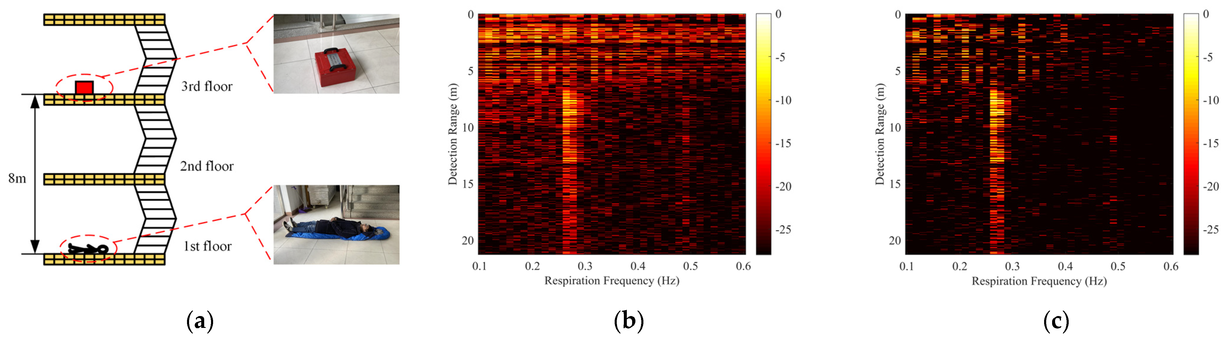
5.3. Detection Performance in Through-Floors Situation

To explore the robustness of the proposed method in different situations, the human respiration detection experiment in the through-floors situation was carried out on the stairs. The tested human was lying on the first floor and breathing steadily, and the UWB impulse radar was placed on the second or third floor, respectively. The single floor has a thickness of about 45 cm and a complex structure with internal wires. Detection scenarios are shown in Figure 12a and Figure 13a.
For the experiment through one floor, as shown in the direct FFT result in Figure 12b, strong clutter with energy comparable to that of the respiration signal was detected at 0–2 and 4–6 m respectively, and covered the whole frequency band of 0.1–0.6 Hz. It can be regarded as the non-stationary clutter introduced by timing jitter of floors’ scattering. Due to the complex experimental scenario, more clutter is also detected at long distances. It is difficult to visually distinguish the respiration signal from the non-stationary clutter. Figure 12c–f shows the range-frequency matrices obtained with different algorithms. Visually, MS, SVD, and the method in [36] cannot effectively remove non-stationary clutter, and the human respiration signal is masked by a large amount of clutter. After being processed by our proposed algorithm, the range-frequency matrix Y was ‘cleaner’, and most of the clutter was suppressed, except for a little clutter at close range. The extraction of the respiration signal with a range of 4 m and a Doppler frequency of 0.16 Hz becomes easier.
For the experiment through two floors, the energy of the human signal is very weak due to the attenuation of the two floors. In the direct FFT result, there was more non-stationary clutter interfering with the respiration signal detection, as shown in Figure 13b. Figure 13f shows that our proposed method outperformed MS, SVD, and the method in [36]. The non-stationary clutter was suppressed and the human respiration signal was retained in the range-frequency matrix Y. There are two peaks in Figure 13f, which can be explained by the multiple-path respiration responses caused by the complex structure of the stairs. It should be noted that we have not changed the value of λ , which is fixed at 0.3.
The corresponding SCNR and IF values for the two scenarios are provided in Table 4. The performance of SVD with the largest principal component removed was comparable to that of MS. The method in [36] had the worst performance. However, our proposed method also had the highest IF score.

6. Conclusions

When using the UWB impulse radar for through-wall human respiration detection, the time interval between successive pulses emitted cannot be guaranteed to be ideally fixed. This results in non-stationary clutter scattered by the stationary target, which affects the extraction of the human respiration signal. We proposed a method for reducing the impact of timing jitter. First, we used cross-correlation to correct the time offset of each impulse response, achieving initial compensation for timing jitter in the time domain. Then, we enhanced the weak respiration signal to improve SCNR. Finally, the difference of sparsity in the frequency dimension between the human respiration signal and the jitter-induced clutter was used to accurately extract the human respiration signal in the frequency domain. The results of numerical simulation and a series of experiments, including through-wall detection and through-floor detection, showed that the proposed algorithm can effectively suppress the non-stationary clutter induced by timing jitter. This will improve the performance of the UWB impulse radar in human detection under NLOS conditions.

Author Contributions

Conceptualization, C.S. and Z.-K.N.; methodology, C.S.; software, S.Y.; validation, J.P. and Z.Z.; formal analysis, C.S.; investigation, J.P.; resources, G.F.; data curation, S.Y.; writing—original draft preparation, C.S.; writing—review and editing, Z.-K.N. and J.P.; visualization, Z.Z.; supervision, S.Y.; project administration, G.F.; funding acquisition, G.F. All authors have read and agreed to the published version of the manuscript.

Funding

This work was supported in part by the National Key Research and Development Program of China under 2018YFC0810202 and in part by the National Natural Science Foundation of China under Grant 61827803.

Institutional Review Board Statement

Not applicable.

Informed Consent Statement

Not applicable.

Data Availability Statement

Data sharing is not applicable to this article.

Conflicts of Interest

The authors declare no conflict of interest.

References

  1. Liu, L.; Fang, G. A novel UWB sampling receiver and its applications for impulse GPR systems. IEEE Geosci. Remote Sens. Lett. 2010, 7, 690–693. [Google Scholar] [CrossRef]
  2. Le, C.; Dogaru, T.; Nguyen, L.; Ressler, M. Ultrawideband (UWB) radar imaging of building interior: Measurements and predictions. IEEE Trans. Geosci. Remote Sens. 2009, 47, 1409–1420. [Google Scholar] [CrossRef]
  3. Huang, Q.; Qu, L.; Wu, B.; Fang, G. UWB through-wall imaging based on compressive sensing. IEEE Trans. Geosci. Remote Sens. 2009, 48, 1408–1415. [Google Scholar] [CrossRef]
  4. Yarovoy, A.G.; Ligthart, L.P.; Matuzas, J.; Levitas, B. UWB radar for human being detection. IEEE Aerosp. Electron. Syst. Mag. 2006, 21, 10–14. [Google Scholar] [CrossRef] [Green Version]
  5. Lv, H.; Lu, G.H.; Jing, X.J.; Wang, J. A new ultra-wideband radar for detecting survivors buried under earthquake rubbles. Microw. Opt. Technol. Lett. 2010, 52, 2621–2624. [Google Scholar] [CrossRef]
  6. Vu, V.T.; Sjogren, T.K.; Pettersson, M.I.; Gustavsson, A.; Ulander, L. Detection of moving targets by focusing in UWB SAR—Theory and experimental results. IEEE Trans. Geosci. Remote Sens. 2010, 48, 3799–3815. [Google Scholar] [CrossRef]
  7. Zhuge, X.; Yarovoy, A.G. A sparse aperture MIMO-SAR-based UWB imaging system for concealed weapon detection. IEEE Trans. Geosci. Remote Sens. 2010, 49, 509–518. [Google Scholar] [CrossRef]
  8. Wu, S.; Tan, K.; Xu, Y.; Chen, J.; Meng, S.; Fang, G. A simple strategy for moving target imaging via an experimental UWB through-wall radar. In Proceedings of the 2012 14th International Conference on Ground Penetrating Radar (GPR), Shanghai, China, 4–8 June 2012; pp. 961–965. [Google Scholar]
  9. Rohman, B.P.A.; Andra, M.B.; Nishimoto, M. Through-the-Wall Human Respiration Detection Using UWB Impulse Radar on Hovering Drone. IEEE J. Sel. Top. Appl. Earth Obs. Remote Sens. 2021, 14, 6572–6584. [Google Scholar] [CrossRef]
  10. Ma, Y.; Qi, F.; Wang, P.; Liang, F.; Lv, H.; Yu, X.; Li, Z.; Xue, H.; Wang, J.; Zhang, Y. Multiscale residual attention network for distinguishing stationary humans and common animals under through-wall condition using ultra-wideband radar. IEEE Access 2020, 8, 121572–121583. [Google Scholar] [CrossRef]
  11. Shen, H.; Xu, C.; Yang, Y.; Sun, L.; Cai, Z.; Bai, L.; Clancy, E.; Huang, X. Respiration and heartbeat rates measurement based on autocorrelation using IR-UWB radar. IEEE Trans. Circuits Syst. II Express Briefs 2018, 65, 1470–1474. [Google Scholar] [CrossRef]
  12. Sachs, J.; Aftanas, M.; Crabbe, S.; Drutarovsky, M.; Klukas, R.; Kocur, D.; Nguyen, T.T.; Peyerl, P.; Rovnakova, J.; Zaikov, E. Detection and tracking of moving or trapped people hidden by obstacles using ultra-wideband pseudo-noise radar. In Proceedings of the 2008 European Radar Conference, Amsterdam, The Netherlands, 30–31 October 2008; pp. 408–411. [Google Scholar]
  13. Yan, K.; Wu, S.; Ye, S.; Fang, G. A Novel Wireless-Netted UWB Life-Detection Radar System for Quasi-Static Person Sensing. Appl. Sci. 2021, 11, 424. [Google Scholar] [CrossRef]
  14. Pan, J.; Ye, S.; Shi, C.; Yan, K.; Liu, X.; Ni, Z.; Yang, G.; Fang, G. 3D imaging of moving targets for ultra-wideband MIMO through-wall radar system. IET Radar Sonar Navigat. 2021, 15, 261–273. [Google Scholar] [CrossRef]
  15. Xia, Z.; Fang, G.; Ye, S.; Zhang, Q.; Chen, C.; Yin, H. A novel handheld pseudo random coded UWB radar for human sensing applications. IEICE Electron. Expr. 2014, 11, 20140981. [Google Scholar] [CrossRef] [Green Version]
  16. Charvat, G.L.; Kempel, L.C.; Rothwell, E.J.; Coleman, C.M.; Mokole, E. A through-dielectric radar imaging system. IEEE Trans. Antennas Propag. 2010, 58, 2594–2603. [Google Scholar] [CrossRef]
  17. Chauhan, S.S.; Basu, A.; Abegaonkar, M.P.; Koul, S.H. Through the Wall Human Subject Localization and Respiration Rate Detection Using Multichannel Doppler Radar. IEEE Sens. J. 2020, 21, 1510–1518. [Google Scholar] [CrossRef]
  18. Wang, G.; Munoz-Ferreras, J.M.; Gu, C.; Li, C.; Gomez-Garcia, R. Application of linear-frequency-modulated continuous-wave (LFMCW) radars for tracking of vital signs. IEEE Trans. Microw. Theory Tech. 2014, 62, 1387–1399. [Google Scholar] [CrossRef]
  19. Wang, G.; Gu, C.; Inoue, T.; Li, C. A hybrid FMCW-interferometry radar for indoor precise positioning and versatile life activity monitoring. IEEE Trans. Microw. Theory Tech. 2014, 62, 2812–2822. [Google Scholar] [CrossRef]
  20. Charvat, G.L.; Kempel, L.C.; Rothwell, E.J.; Coleman, C.M.; Mokole, E.L. A through-dielectric ultrawideband (UWB) switched-antenna-array radar imaging system. IEEE Trans. Antennas Propag. 2012, 60, 5495–5500. [Google Scholar] [CrossRef]
  21. Browne, K.E.; Burkholder, R.J.; Volakis, J.L. Through-wall opportunistic sensing system utilizing a low-cost flat-panel array. IEEE Trans. Antennas Propag. 2010, 59, 859–868. [Google Scholar] [CrossRef]
  22. Liu, L.; Liu, S. Remote detection of human vital sign with stepped-frequency continuous wave radar. IEEE J. Sel. Top. Appl. Earth Obs. Remote Sens. 2014, 7, 775–782. [Google Scholar] [CrossRef]
  23. Lu, B.; Song, Q.; Zhou, Z.; Wang, H. A SFCW radar for through wall imaging and motion detection. In Proceedings of the 2011 8th European Radar Conference, Manchester, UK, 12–14 October 2011; pp. 325–328. [Google Scholar]
  24. Lu, B.; Song, Q.; Zhou, Z.; Zhang, X. Detection of human beings in motion behind the wall using SAR interferogram. IEEE Geosci. Remote Sens. Lett. 2012, 9, 968–971. [Google Scholar]
  25. Lazaro, A.; Girbau, D.; Villarino, R. Analysis of vital signs monitoring using an IR-UWB radar. Progr. Electromagn. Res. 2010, 100, 265–284. [Google Scholar] [CrossRef] [Green Version]
  26. Sharafi, A.; Baboli, M.; Eshghi, M.; Ahmadian, A. Respiration-rate estimation of a moving target using impulse-based ultra wideband radars. Australas. Phys. Eng. Sci. Med. 2012, 35, 31–39. [Google Scholar] [CrossRef] [PubMed]
  27. Liu, L.; Liu, Z.; Barrowes, B.E. Through-wall bio-radiolocation with UWB impulse radar: Observation, simulation and signal extraction. IEEE J. Sel. Top. Appl. Earth Obs. Remote Sens. 2011, 4, 791–798. [Google Scholar] [CrossRef]
  28. Tigrini, A.; Mengarelli, A.; Cardarelli, S.; Fioretti, S.; Verdini, F. Improving EMG Signal Change Point Detection for Low SNR by Using Extended Teager-Kaiser Energy Operator. IEEE Trans. Med. Robot. Bionics 2020, 2, 661–669. [Google Scholar] [CrossRef]
  29. Hua, X.; Ono, Y.; Peng, L.; Cheng, Y.; Wang, H. Target Detection within Nonhomogeneous Clutter via Total Bregman Divergence-Based Matrix Information Geometry Detectors. IEEE Trans. Signal Process. 2021, 69, 4326–4340. [Google Scholar] [CrossRef]
  30. Kumaragamage, C.L.; Lithgow, B.J.; Moussavi, Z.K. Investigation of a new weighted averaging method to improve SNR of electrocochleography recordings. IEEE Trans. Biomed. Eng. 2015, 63, 340–347. [Google Scholar] [CrossRef]
  31. Boyd, S.W.; Pursley, M.B. Enhanced SNR estimates from direct-sequence spread-spectrum demodulator statistics. IEEE Commun. Lett. 2009, 13, 289–291. [Google Scholar] [CrossRef]
  32. Nezirovic, A. Stationary clutter-and linear-trend suppression in impulse-radar-based respiratory motion detection. In Proceedings of the 2011 IEEE International Conference on Ultra-Wideband (ICUWB), Bologna, Italy, 14–16 September 2011; pp. 331–335. [Google Scholar]
  33. Venkatesh, S.; Anderson, C.R.; Rivera, N.V.; Buehrer, R.M. Implementation and analysis of respiration-rate estimation using impulse-based UWB. In Proceedings of the 2005 IEEE Military Communications Conference, Atlantic City, NJ, USA, 17–20 October 2005; pp. 3314–3320. [Google Scholar]
  34. Xu, Y.; Dai, S.; Wu, S.; Chen, J.; Fang, G.Y. Vital sign detection method based on multiple higher order cumulant for ultrawideband radar. IEEE Trans. Geosci. Remote Sens. 2011, 50, 1254–1265. [Google Scholar] [CrossRef]
  35. Nezirovic, A.; Yarovoy, A.G.; Ligthart, L.P. Signal processing for improved detection of trapped victims using UWB radar. IEEE Trans. Geosci. Remote Sens. 2009, 48, 2005–2014. [Google Scholar] [CrossRef]
  36. Hu, J.; Tu, X.; Zhu, G.; Li, Y.; Zhou, Z. Coupling suppression in human target detection via impulse through wall radar. In Proceedings of the 2013 14th International Radar Symposium (IRS), Dresden, Germany, 19–21 June 2013; pp. 1008–1012. [Google Scholar]
  37. Li, Z.; Li, W.; Lv, H.; Zhang, Y.; Jing, X.; Wang, J. A novel method for respiration-like clutter cancellation in life detection by dual-frequency IR-UWB radar. IEEE Trans. Microw. Theory Tech. 2013, 61, 2086–2092. [Google Scholar] [CrossRef]
  38. Zhuang, L.; Bioucas-Dias, J.M. Fast hyperspectral image denoising and inpainting based on low-rank and sparse representations. IEEE J. Sel. Top. Appl. Earth Obs. Remote Sens. 2018, 11, 730–742. [Google Scholar] [CrossRef]
  39. Sun, W.; Yang, G.; Du, B.; Zhang, L.; Zhang, L. A sparse and low-rank near-isometric linear embedding method for feature extraction in hyperspectral imagery classification. IEEE Trans. Geosci. Remote Sens. 2017, 55, 4032–4046. [Google Scholar] [CrossRef]
  40. Peng, Y.; Ganesh, A.; Wright, J.; Xu, W.; Ma, Y. RASL: Robust alignment by sparse and low-rank decomposition for linearly correlated images. IEEE Trans. Pattern Anal. Mach. Intell. 2012, 34, 2233–2246. [Google Scholar] [CrossRef]
  41. Zheng, A.; Zou, T.; Zhao, Y.; Jiang, B.; Tang, J.; Li, C. Background subtraction with multi-scale structured low-rank and sparse factorization. Neurocomputing 2019, 328, 113–121. [Google Scholar] [CrossRef]
  42. Hu, J.; Jiang, T.; Cui, Z.; Hou, T. Design of UWB pulses based on Gaussian pulse. In Proceedings of the 2008 3rd IEEE International Conference on Nano/Micro Engineered and Molecular Systems, Sanya, China, 6–9 January 2008; pp. 651–655. [Google Scholar]
  43. Liang, X.; Zhang, H.; Fang, G.; Ye, S.; Gulliver, T. An improved algorithm for through-wall target detection using ultra-wideband impulse radar. IEEE Access 2017, 5, 22101–22118. [Google Scholar] [CrossRef]
  44. Nahar, S.; Phan, T.; Quaiyum, F.; Ren, L.; Fathy, A.E.; Kilic, O. An electromagnetic model of human vital signs detection and its experimental validation. IEEE J. Emerg. Sel. Top. Circuits Syst. 2018, 8, 338–349. [Google Scholar] [CrossRef]
  45. Kalashnikov, A.N.; Challis, R.E.; Unwin, M.E.; Holmes, A.K. Effects of frame jitter in data acquisition systems. IEEE Trans. Instrum. Meas. 2005, 54, 2177–2183. [Google Scholar] [CrossRef]
  46. Hu, J.; Zhu, G.; Jin, T.; Wang, L.; Zhou, Z. Study on timing jitter in clutter mitigation of through-wall human indication. In Proceedings of the 2013 IEEE International Conference on Ultra-Wideband (ICUWB), Sydney, Australia, 15–18 September 2013; pp. 211–214. [Google Scholar]
  47. Shinagawa, M.; Akazawa, Y.; Wakimoto, T. Jitter analysis of high-speed sampling systems. IEEE J. Solid-State Circuits 1990, 25, 220–224. [Google Scholar] [CrossRef]
  48. Zetik, R.; Crabbe, S.; Krajnak, J.; Peyerl, P.; Sachs, J.; Thoma, R. Detection and localization of persons behind obstacles using M-sequence through-the-wall radar. In Proceedings of the Sensors, and Command, Control, Communications, and Intelligence (C3I) Technologies for Homeland Security and Homeland Defense V, Orlando, FL, USA, 10 May 2006; p. 6201. [Google Scholar]
  49. Wu, S.; Yao, S.; Liu, W.; Tan, K.; Xia, Z.; Meng, S.; Chen, J.; Fang, G.; Yin, H. Study on a novel UWB linear array human respiration model and detection method. IEEE J. Sel. Top. Appl. Earth Obs. Remote Sens. 2016, 9, 125–140. [Google Scholar] [CrossRef]
  50. Yoon, Y.S.; Kim, D.; Yoon, J.; Choi, S. Iterative Robust PCA method to detect landmines in Ground Penetrating Radar. In Proceedings of the 2019 IEEE Radar Conference (RadarConf), Boston, MA, USA, 22–26 April 2019; pp. 1–6. [Google Scholar]
  51. Peng, X.; Lu, C.; Yi, Z.; Tang, H. Connections between nuclear-norm and frobenius-norm-based representations. IEEE Trans. Neural Netw. Learn. Syst. 2016, 29, 218–224. [Google Scholar] [CrossRef] [PubMed] [Green Version]
  52. Zhang, L.; Yang, M.; Feng, X. Sparse representation or collaborative representation: Which helps face recognition? In Proceedings of the 2011 International Conference on Computer Vision, Barcelona, Spain, 6–13 November 2011; pp. 471–478. [Google Scholar]
  53. Peng, X.; Lu, J.; Yi, Z.; Yan, R. Automatic subspace learning via principal coefficients embedding. IEEE Trans. Cybern. 2016, 47, 3583–3596. [Google Scholar] [CrossRef] [Green Version]
  54. Zhang, L.; Chen, Z.; Zheng, M.; He, X. Robust non-negative matrix factorization. Front. Electr. Electron. Eng. China 2011, 6, 192–200. [Google Scholar] [CrossRef]
  55. Sha, F.; Lin, Y.; Saul, L.K.; Lee, D.D. Multiplicative updates for nonnegative quadratic programming. Neural Comput. 2007, 19, 2004–2031. [Google Scholar] [CrossRef]
  56. Hale, E.T.; Yin, W.; Zhang, Y. Fixed-point continuation for l1-minimization: Methodology and convergence. SIAM J. Optim. 2008, 19, 1107–1130. [Google Scholar] [CrossRef]
  57. Yang, G.; Ye, S.; Ji, Y.; Zhang, X.; Fang, G. Radiation Enhancement of an Ultrawideband Unidirectional Folded Bowtie Antenna for GPR Applications. IEEE Access 2020, 8, 182218–182228. [Google Scholar] [CrossRef]
Figure 1. Under the condition that there is only one human target and one stationary target in the detection area, impulse responses recorded by the ultra-wideband (UWB) radar: (a) without timing jitter, and (b) with timing jitter.
Remotesensing 13 03577 g001
Figure 2. Schematic of the distortion caused by timing jitter.
Remotesensing 13 03577 g002
Figure 3. Flowchart of the proposed method.
Remotesensing 13 03577 g003
Figure 4. The simulation scenario.
Remotesensing 13 03577 g004
Figure 5. Simulated results. (a) The direct Fast Fourier transform (FFT) result of the raw echo signal without timing jitter, and (b) the direct FFT result of the raw echo signal with timing jitter.
Remotesensing 13 03577 g005
Figure 6. Results for the simulated data processed by different methods. (a) The result processed by mean subtraction (MS), (b) the result processed by singular value decomposition (SVD), (c) the result processed by the method in [36], and (d) the result processed by our method, where λ = 10.
Remotesensing 13 03577 g006aRemotesensing 13 03577 g006b
Figure 7. The blocks of the used UWB impulse radar.
Remotesensing 13 03577 g007
Figure 8. The output balanced pulses of the transmitter. (a) Measurement result in time domain, and (b) calculated power spectrum.
Remotesensing 13 03577 g008
Figure 9. Timing jitter measurement bench and results. (a) The measurement bench, and (b) the measurement results.
Remotesensing 13 03577 g009
Figure 10. The realistic through-wall detection scenario.
Remotesensing 13 03577 g010
Figure 11. Realistic through-wall detection results. (a) The raw echo matrix, (b) the direct FFT result, (c) the result processed by MS, (d) the result processed by SVD, (e) the result processed by the method in [36], and (f) the result processed by our method, where λ = 0.3.
Remotesensing 13 03577 g011aRemotesensing 13 03577 g011b
Figure 12. Realistic through-one-floor detection scenario and results. (a) The realistic through-one-floor detection scenario, (b) the direct FFT result, (c) the result processed by MS, (d) the result processed by SVD, (e) the result processed by the method in [36], and (f) the result processed by our method, where λ = 0.3.
Remotesensing 13 03577 g012
Figure 13. Realistic through-two-floors detection scenario and results. (a) The realistic through-two-floors detection scenario, (b) the direct FFT result, (c) the result processed by MS, (d) the result processed by SVD, (e) the result processed by the method in [36], and (f) the result processed by our method, where λ = 0.3.
Remotesensing 13 03577 g013aRemotesensing 13 03577 g013b
Table 1. Quantitative results of simulation.
MethodSCNRIF
FFT19.96-
MS28.038.07
SVD27.767.80
The method in [36]32.0312.07
The proposed method33.4113.45
Table 2. Parameters of the radar.
ParameterValue
Pulse waveformGaussian pulse
−10 dB bandwidth433 MHz
Amplitude of transmitted signal303 V
Pulse repeated frequency32 KHz
Average number128
Fast-time sampling rate16 GHz
Slow-time sampling rate15 Hz
Sampling points4096
Table 3. Quantitative results of the through-wall detection.
MethodSCNRIF
FFT14.34-
MS18.143.80
SVD16.321.98
The method in [36]15.010.67
The proposed method35.0820.74
Table 4. Quantitative results of the through-floors detection.
MethodThrough One FloorThrough Two Floors
SCNRIFSCNRIF
FFT13.83-12.38
MS19.625.7918.155.77
SVD18.644.8116.564.18
The method in [36]14.520.6912.980.60
The proposed method38.0124.1829.4017.02
Publisher’s Note: MDPI stays neutral with regard to jurisdictional claims in published maps and institutional affiliations.

