Through-Wall Human Pose Reconstruction via UWB MIMO Radar and 3D CNN

Abstract
1. Introduction
- A novel pose reconstruction framework is developed to solve the 3D pose reconstruction problem of occluded human targets.
- It is the first pose reconstruction approach that uses low-frequency UWB MIMO radar as the detect sensor, which has better penetrating performance; it can penetrate many materials such as curtain, wood, plastic board, brick wall and so on, making it applicable to more complex indoor scenes.
- We adopt the sequence of large-scale 2D imaging, and then fine 3D imaging to process radar signals. As compared with the method of direct 3D imaging to radar signal, our method ensures imaging efficiency and imaging quality simultaneously.
- A special 3D CNN is designed to reconstruct 3D poses from 3D images. Taking the type and characteristics of the input data into consideration, an end-to-end 3D CNN is contrived to operate supervised learning.
2. Materials
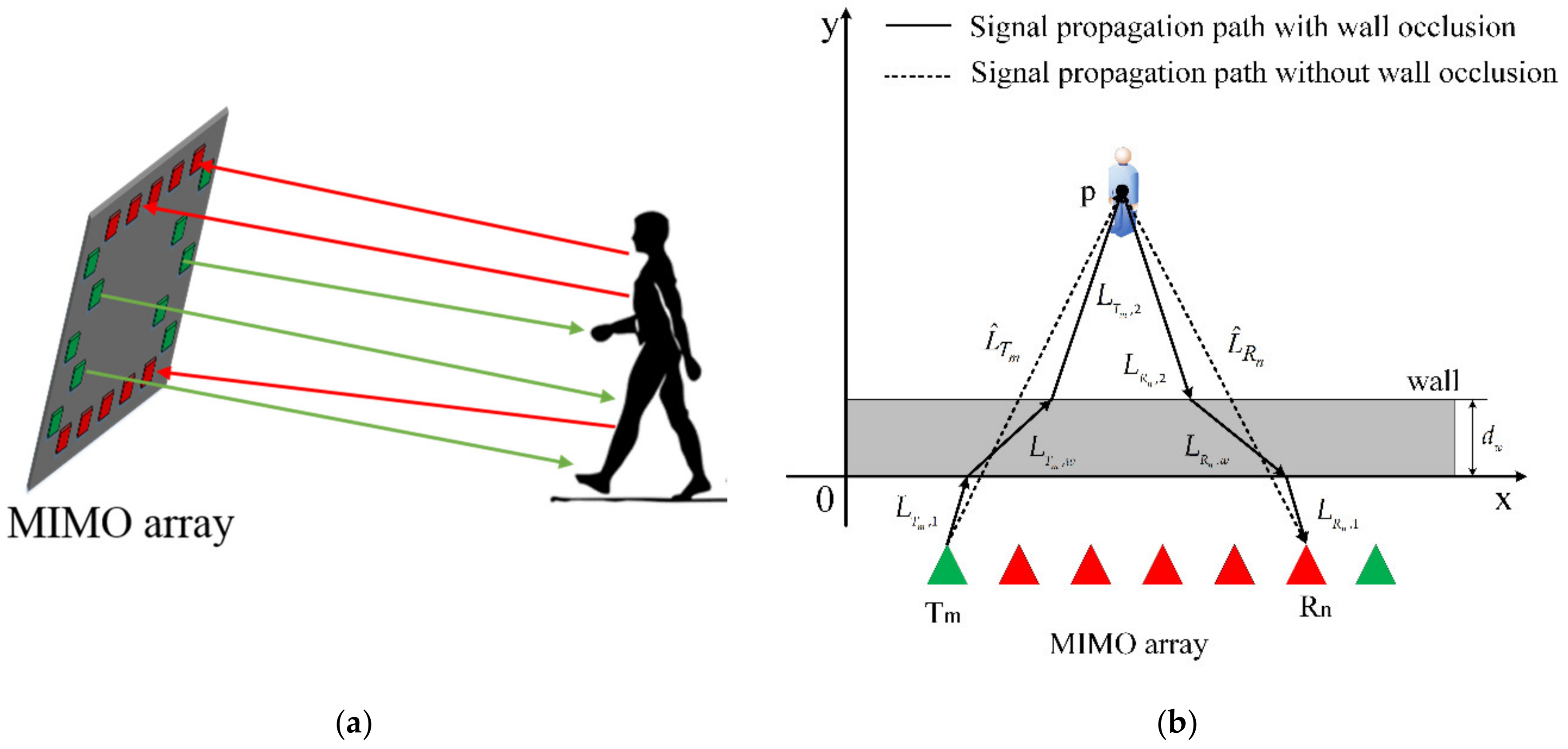
2.1. Multiple-Input Multiple-Output (MIMO) Radar through-Wall Imaging
2.1.1. MIMO Radar
2.1.2. Back-Projection Imaging of MIMO Radar
2.1.3. Through-Wall Target Imaging
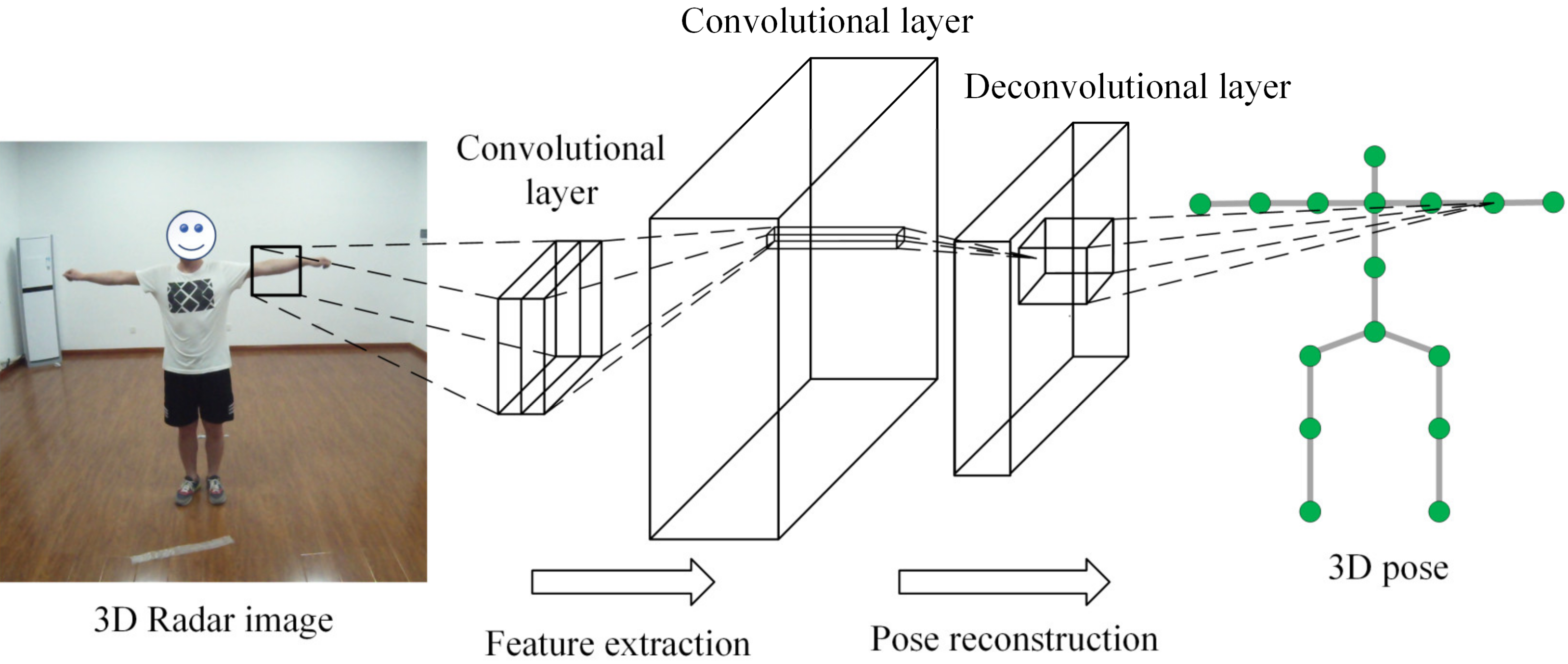
2.2. Convolutional Neural Network (CNN) for Pose Reconstruction
3. Methods
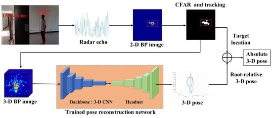
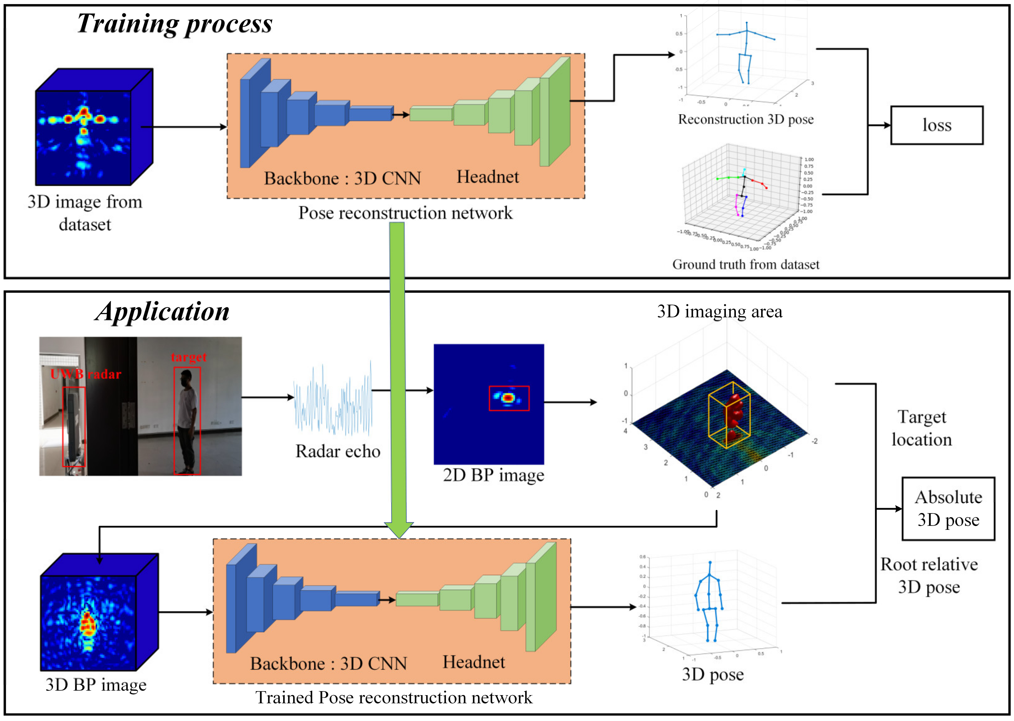
3.1. The Proposed Framework
3.2. Implementation
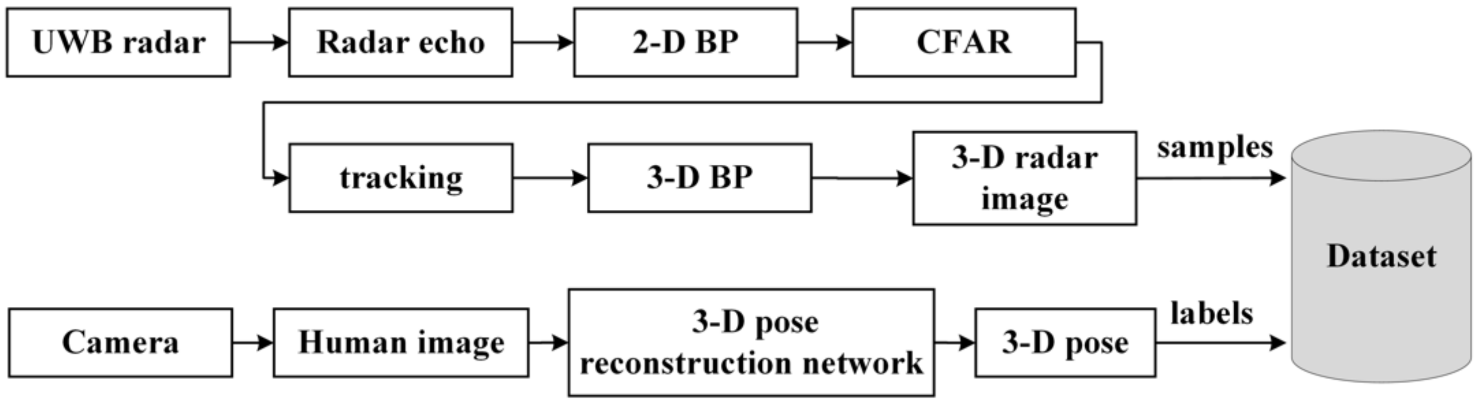
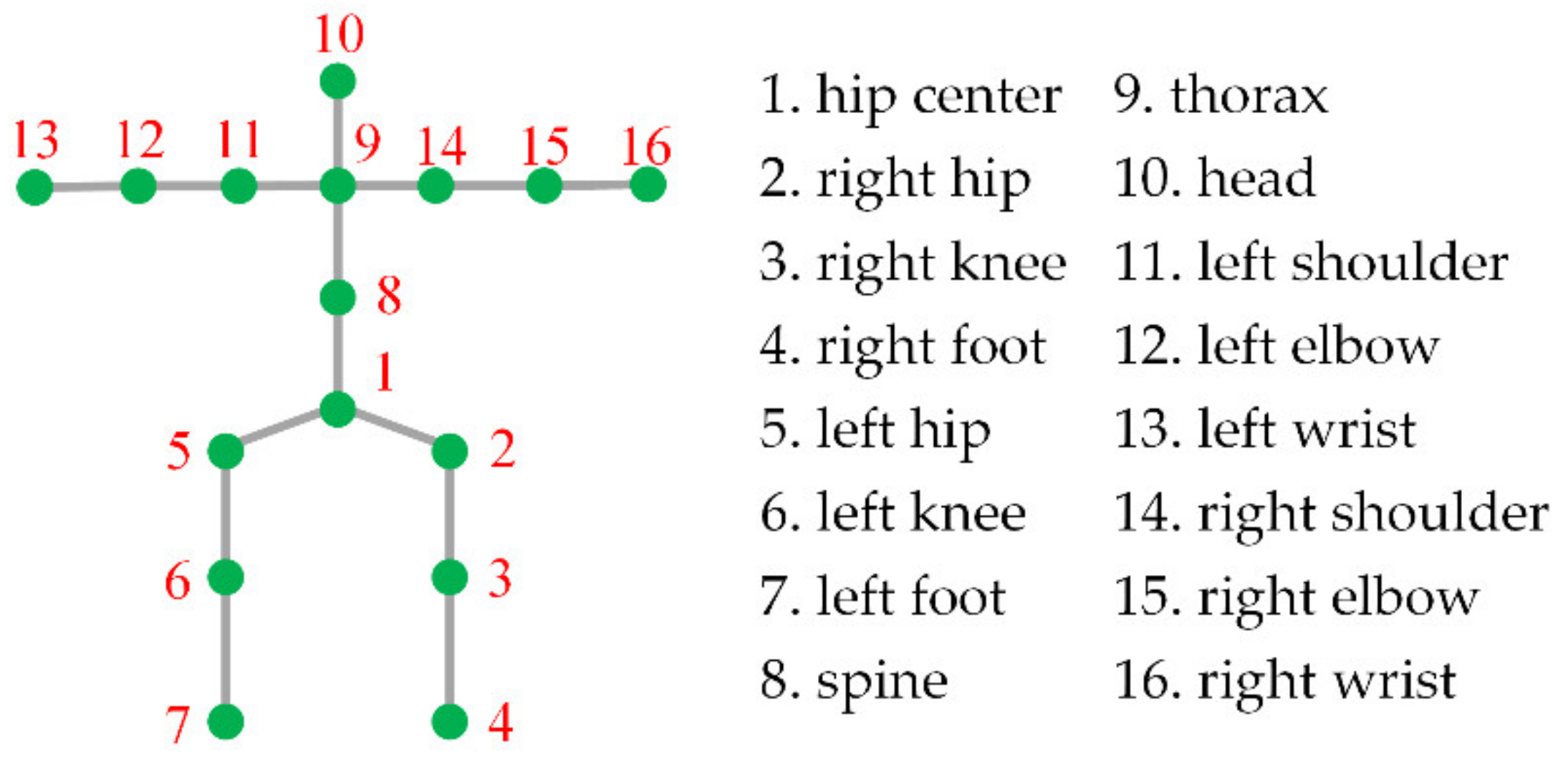
3.2.1. Dataset
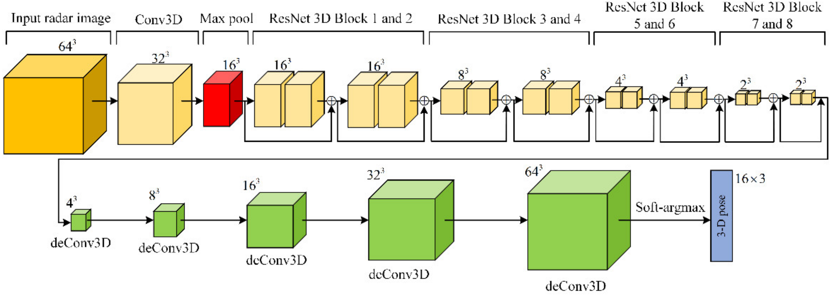
3.2.2. Network Architecture
3.2.3. Loss Function
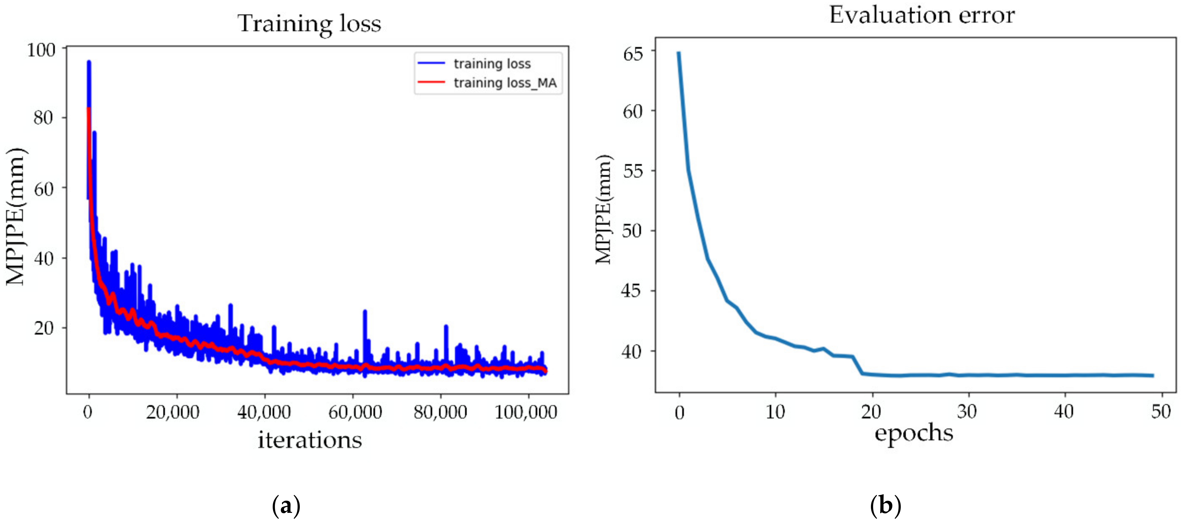
3.2.4. Training Details
4. Results
4.1. Network Evaluation
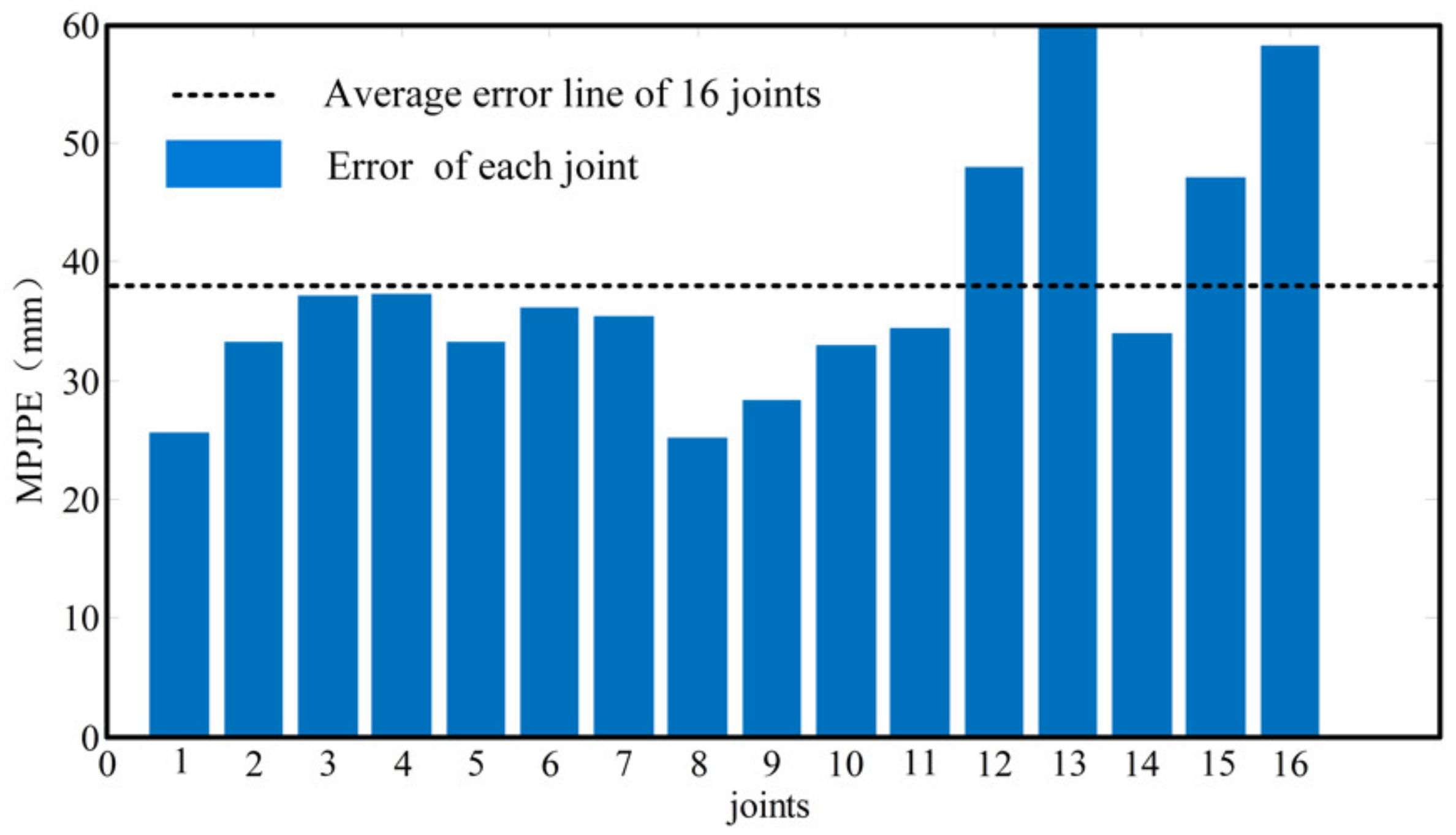
4.1.1. Test Results and Analysis
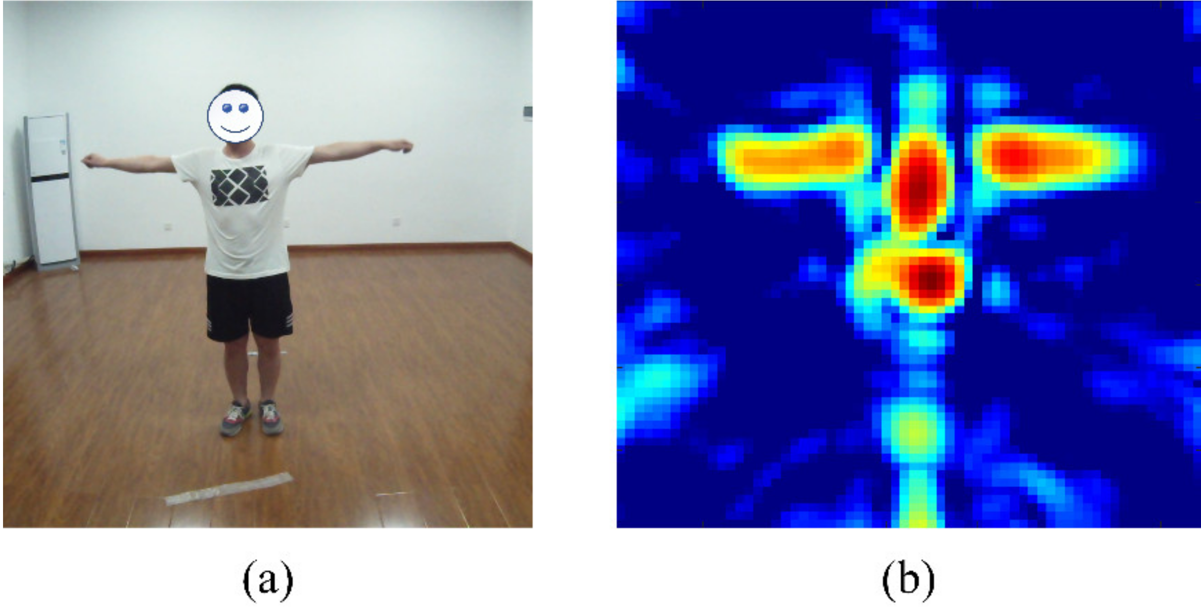
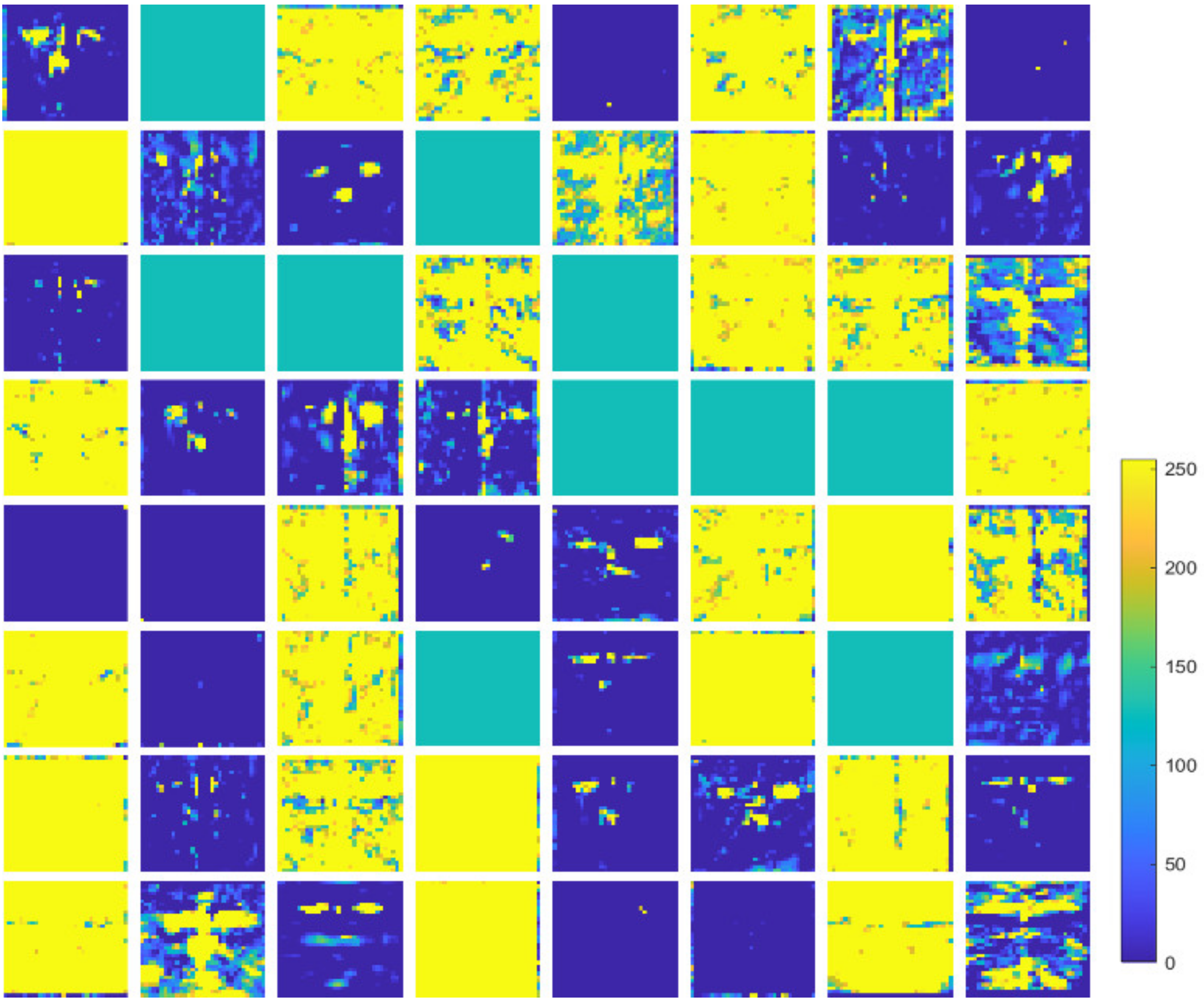
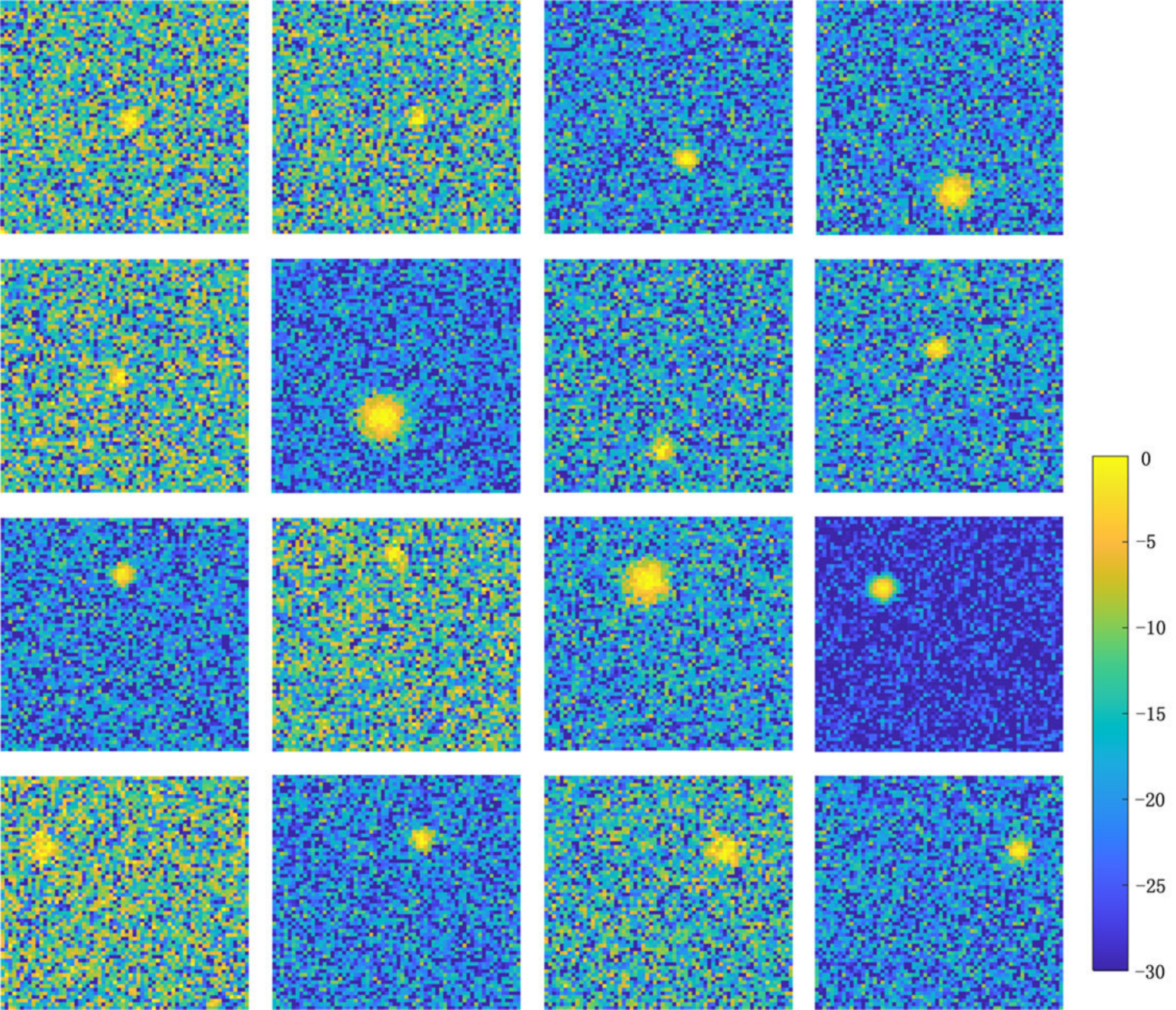
4.1.2. Feature Analysis
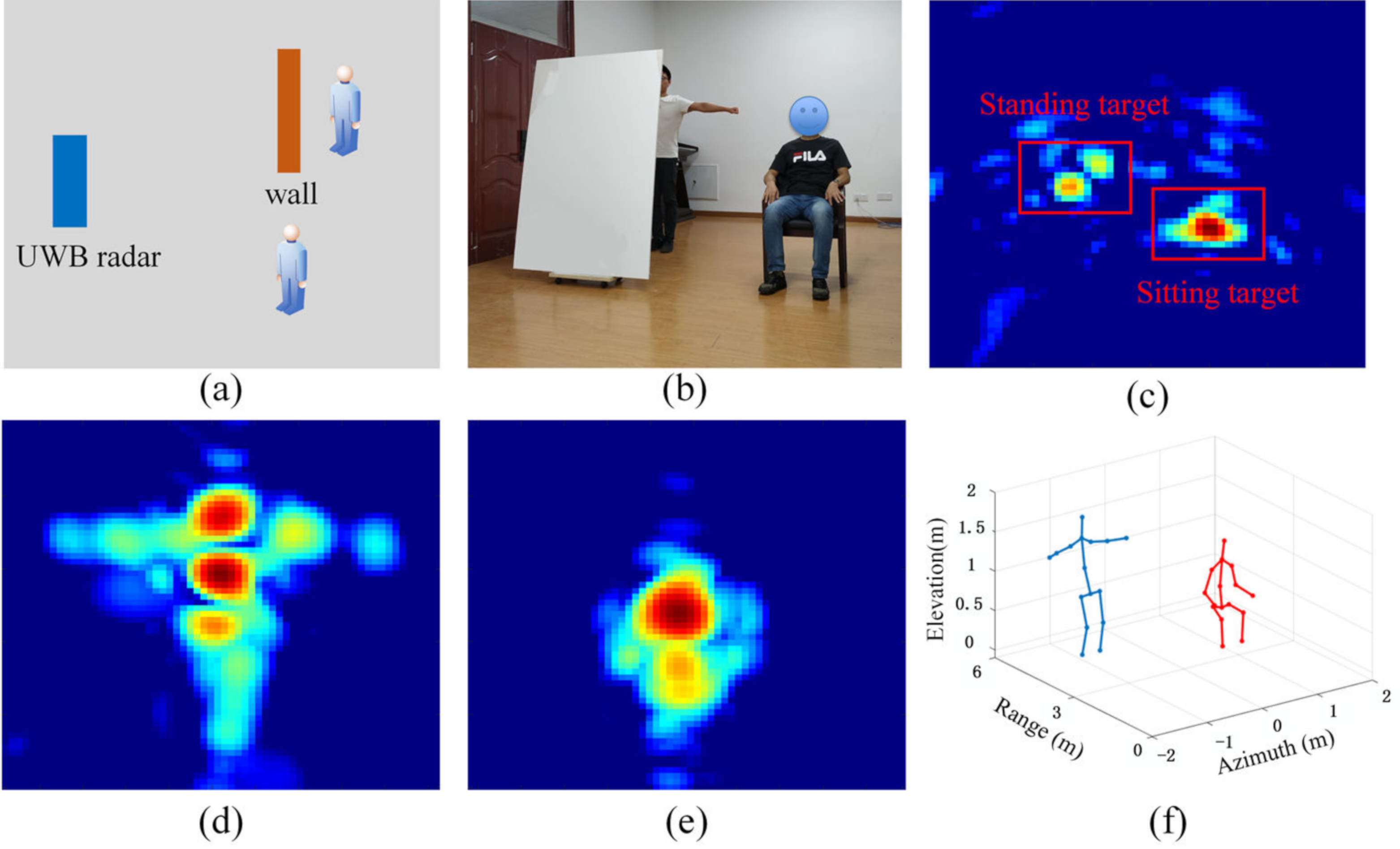
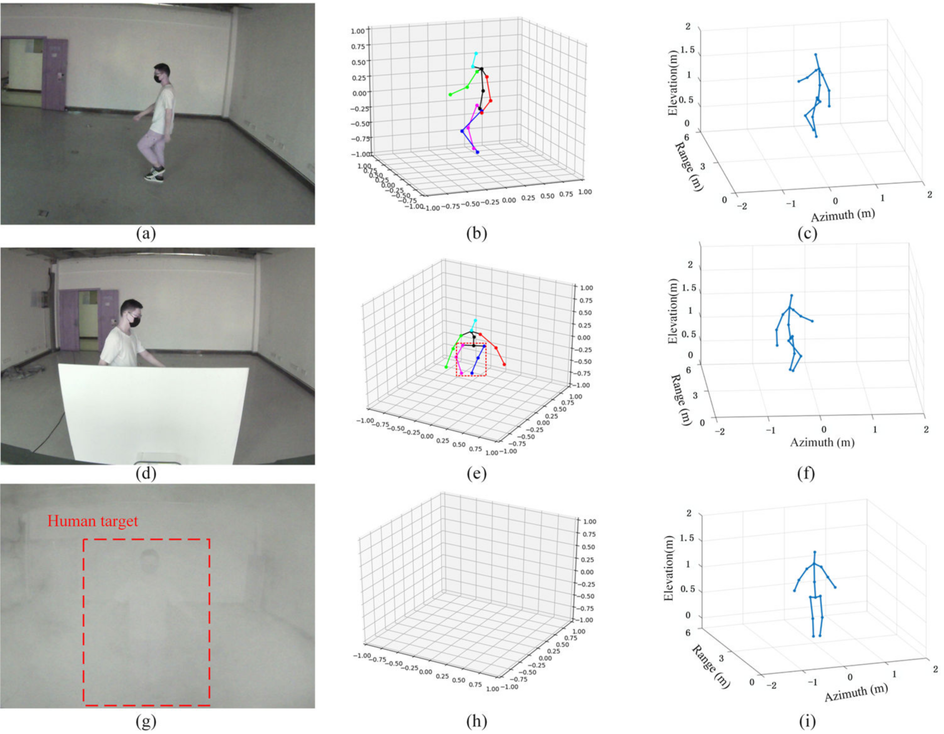
4.2. Field Experiments
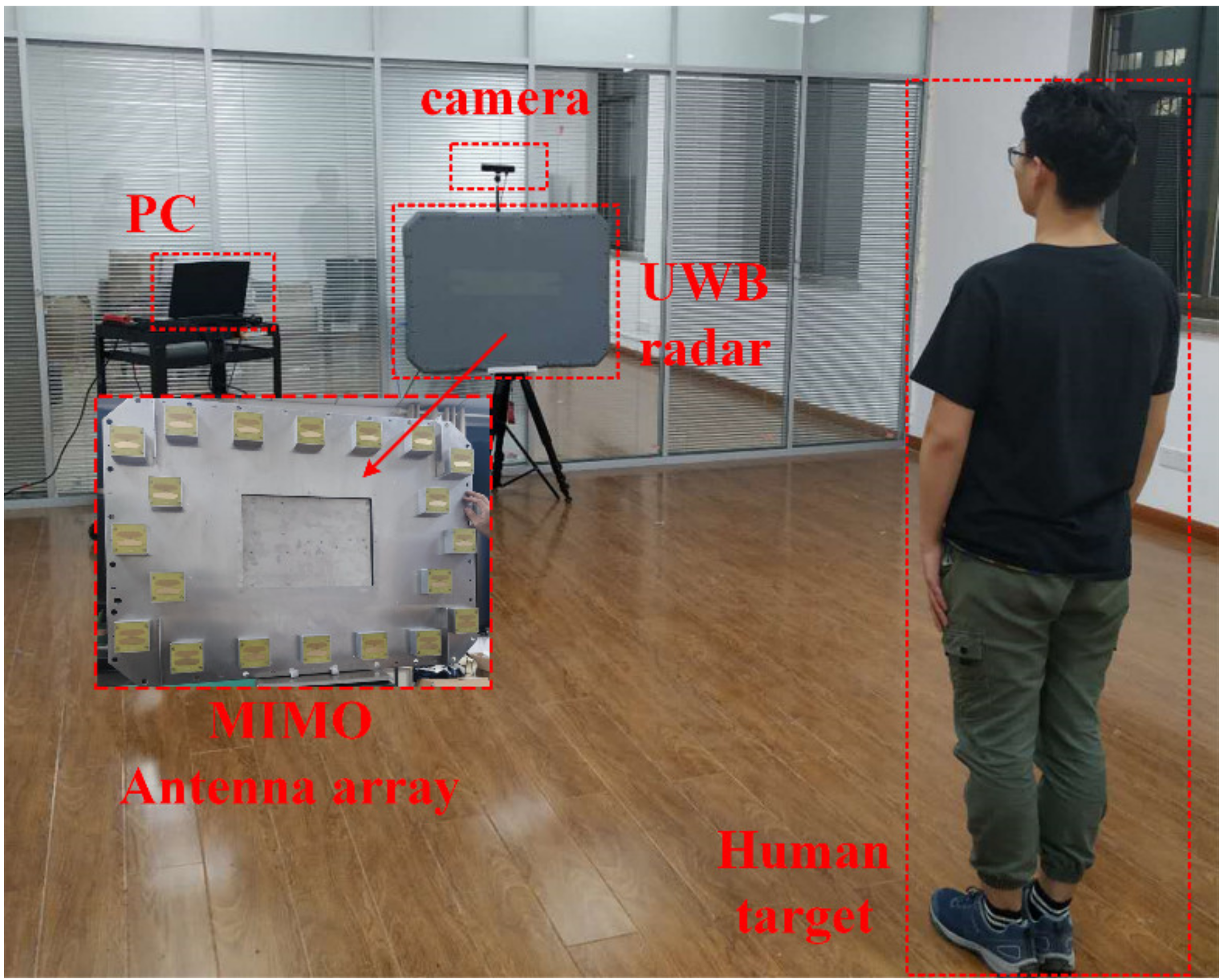
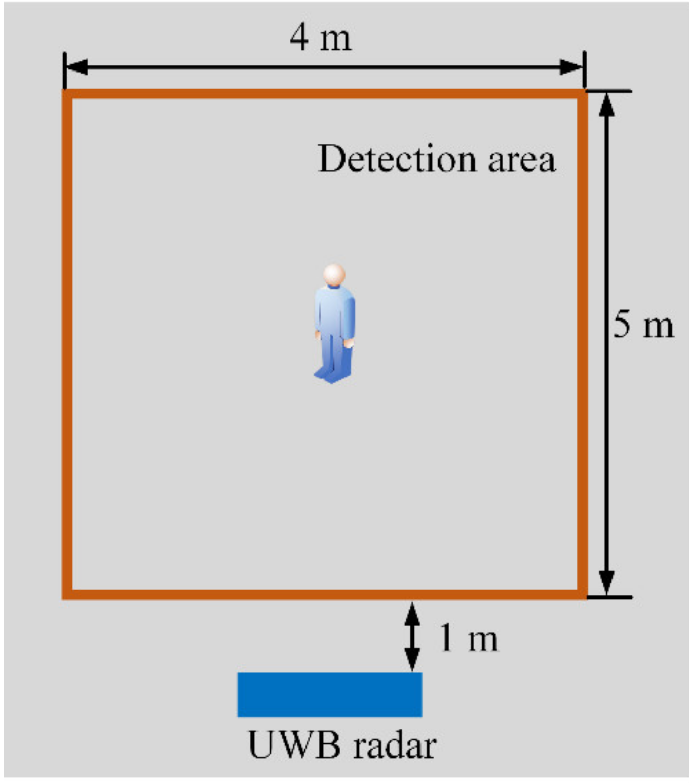
4.2.1. Experimental Setup
4.2.2. Multiple Scene Experiments
4.2.3. Comparison with Optical Method
4.2.4. Performance Comparison
4.2.5. Computation Time Analysis
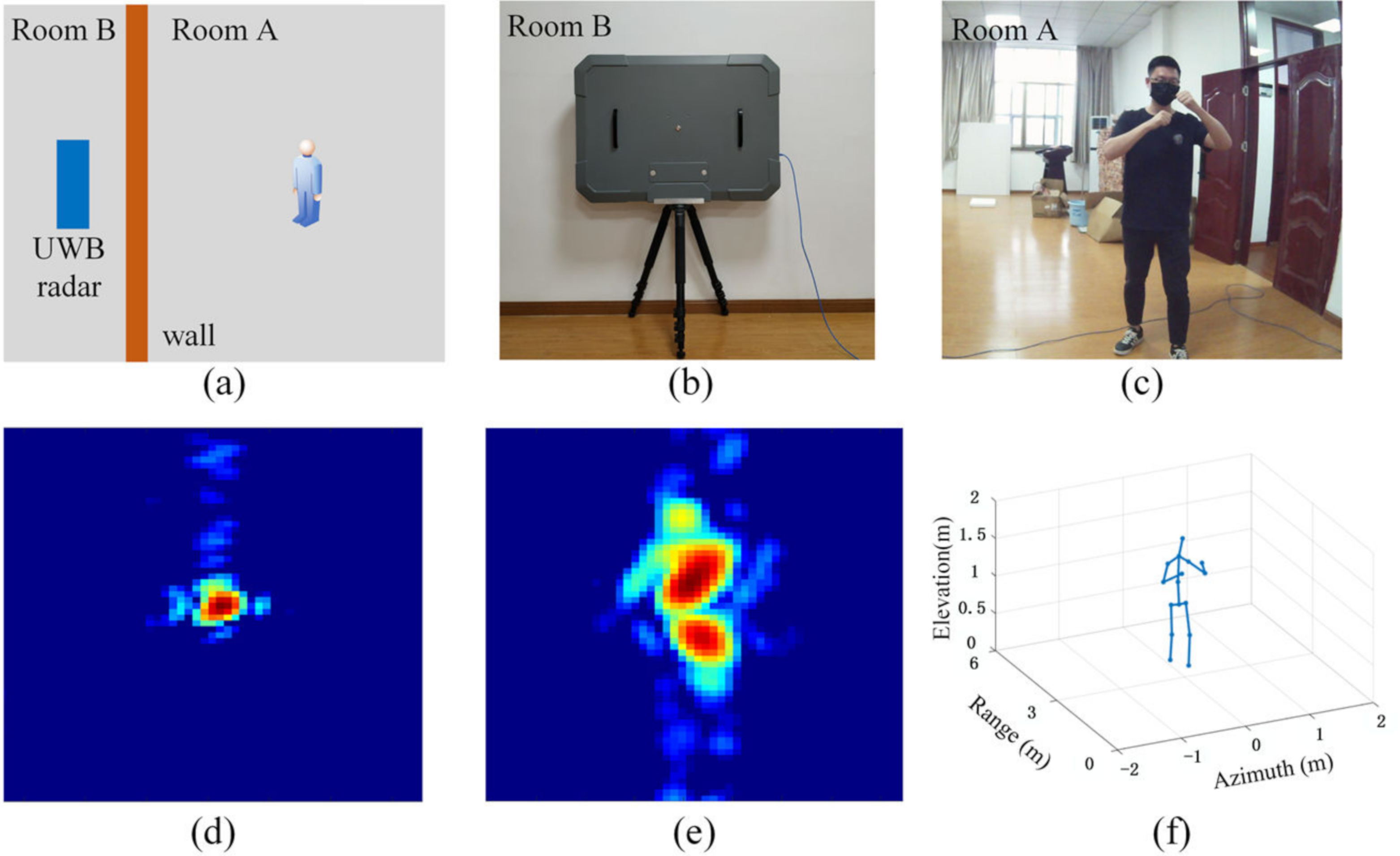
4.2.6. Through-Wall Detection Performance
5. Discussion
6. Conclusions
Author Contributions
Funding
Institutional Review Board Statement
Informed Consent Statement
Data Availability Statement
Acknowledgments
Conflicts of Interest
References
- Poppe, R.W. A survey on vision-based human action recognition. Image Vis. Comput. 2010, 28, 976–990. [Google Scholar] [CrossRef]
- Guo, Y.; He, D.; Chai, L. A Machine Vision-Based Method for Monitoring Scene-Interactive Behaviors of Dairy Calf. Animals 2020, 10, 190. [Google Scholar] [CrossRef] [PubMed]
- Costa, D.G. Visual Sensors Hardware Platforms: A Review. IEEE Sens. J. 2020, 20, 4025–4033. [Google Scholar] [CrossRef]
- Muhammad, K.; Rodrigues, J.J.P.C.; Kozlov, S.; Piccialli, F.; De Albuquerque, V.H.C. Energy-Efficient Monitoring of Fire Scenes for Intelligent Networks. IEEE Netw. 2020, 34, 108–115. [Google Scholar] [CrossRef]
- Oghaz, M.M.D.; Razaak, M.; Kerdegari, H.; Argyriou, V.; Remagnino, P. Scene and Environment Monitoring Using Aerial Imagery and Deep Learning. In Proceedings of the 2019 15th International Conference on Distributed Computing in Sensor Systems (DCOSS), Santorini, Greece, 29–31 May 2019; pp. 362–369. [Google Scholar]
- Oulton, J.A. The Global Nursing Shortage: An Overview of Issues and Actions. Policy Politics Nurs. Pract. 2006, 7, 34S–39S. [Google Scholar] [CrossRef]
- Liu, H.; Wang, L. Gesture recognition for human-robot collaboration: A review. Int. J. Ind. Ergon. 2018, 68, 355–367. [Google Scholar] [CrossRef]
- Zhang, F.; Zhu, X.; Ye, M. Fast Human Pose Estimation. In Proceedings of the 2019 IEEE/CVF Conference on Computer Vision and Pattern Recognition (CVPR), Long Beach, CA, USA, 16–20 June 2019; pp. 3512–3521. [Google Scholar]
- Gilbert, A.; Trumble, M.; Malleson, C.; Hilton, A.; Collomosse, J. Fusing Visual and Inertial Sensors with Semantics for 3D Human Pose Estimation. Int. J. Comput. Vis. 2019, 127, 381–397. [Google Scholar] [CrossRef]
- Dalal, N.; Triggs, B. Histograms of oriented gradients for human detection. In Proceedings of the IEEE International Conference on Computer Vision and Pattern Recognition (CVPR), San Diego, CA, USA, 20–26 June 2005; Volume 1, pp. 886–893. [Google Scholar]
- LeCun, Y.; Boser, B.; Denker, J.S.; Henderson, D.; Howard, R.E.; Hubbard, W.; Jackel, L.D. Backpropagation Applied to Handwritten Zip Code Recognition. Neural Comput. 1989, 1, 541–551. [Google Scholar] [CrossRef]
- Toshev, A.; Szegedy, C. DeepPose: Human Pose Estimation via Deep Neural Networks. In Proceedings of the 2014 IEEE Conference on Computer Vision and Pattern Recognition, Columbus, OH, USA, 23–28 June 2014; pp. 1653–1660. [Google Scholar]
- Cao, Z.; Simon, T.; Wei, S.-E.; Sheikh, Y. Realtime Multi-person 2D Pose Estimation Using Part Affinity Fields. In Proceedings of the 2017 IEEE Conference on Computer Vision and Pattern Recognition (CVPR), Honolulu, HI, USA, 21–26 July 2017; pp. 1302–1310. [Google Scholar]
- He, K.; Gkioxari, G.; Dollar, P.; Girshick, R. Mask R-CNN. In Proceedings of the 2017 IEEE International Conference on Computer Vision (ICCV), Venice, Italy, 22–29 October 2017; pp. 2980–2988. [Google Scholar]
- Couteaux, V.; Si-Mohamed, S.; Nempont, O.; Lefevre, T.; Popoff, A.; Pizaine, G.; Villain, N.; Bloch, I.; Cotten, A.; Boussel, L. Automatic knee meniscus tear detection and orientation classification with Mask-RCNN. Diagn. Interv. Imaging 2019, 100, 235–242. [Google Scholar] [CrossRef]
- Pishchulin, L.; Insafutdinov, E.; Tang, S.; Andres, B.; Andriluka, M.; Gehler, P.; Schiele, B. DeepCut: Joint Subset Partition and Labeling for Multi Person Pose Estimation. In Proceedings of the 2016 IEEE Conference on Computer Vision and Pattern Recognition (CVPR), Las Vegas, NV, USA, 27–30 June 2016; pp. 4929–4937. [Google Scholar]
- Chen, Y.; Wang, Z.; Peng, Y.; Zhang, Z.; Yu, G.; Sun, J. Cascaded Pyramid Network for Multi-person Pose Estimation. In Proceedings of the 2018 IEEE/CVF Conference on Computer Vision and Pattern Recognition, Salt Lake City, UT, USA, 18–22 June 2018; pp. 7103–7112. [Google Scholar]
- Fang, H.-S.; Xie, S.; Tai, Y.-W.; Lu, C. RMPE: Regional Multi-person Pose Estimation. In Proceedings of the 2017 IEEE International Conference on Computer Vision (ICCV), Venice, Italy, 22–29 October 2017; pp. 2353–2362. [Google Scholar]
- Tome, D.; Russell, C.; Agapito, L. Lifting from the Deep: Convolutional 3D Pose Estimation from a Single Image. In Proceedings of the 2017 IEEE Conference on Computer Vision and Pattern Recognition (CVPR), Honolulu, HI, USA, 21–26 July 2017; pp. 5689–5698. [Google Scholar]
- Pavlakos, G.; Zhou, X.; Derpanis, K.G.; Daniilidis, K. Coarse-to-Fine volumetric prediction for single-image 3d human pose. In Proceedings of the IEEE Conference on Computer Vision and Pattern Recognition (CVPR), Honolulu, HI, USA, 21–26 July 2017; pp. 1263–1272. [Google Scholar]
- Zhou, X.; Huang, Q.; Sun, X.; Xue, X.; Wei, Y. Towards 3D Human Pose Estimation in the Wild: A Weakly-Supervised Ap-proach. In Proceedings of the IEEE International Conference on Computer Vision, Venice, Italy, 22–29 October 2017; pp. 398–407. [Google Scholar]
- Wandt, B.; Rosenhahn, B. RepNet: Weakly Supervised Training of an Adversarial Reprojection Network for 3D Human Pose Estimation. In Proceedings of the 2019 IEEE/CVF Conference on Computer Vision and Pattern Recognition (CVPR), Long Beach, CA, USA, 16–20 June 2019; pp. 7774–7783. [Google Scholar]
- Buys, K.; Cagniart, C.; Baksheev, A.; De Laet, T.; De Schutter, J.; Pantofaru, C. An adaptable system for RGB-D based human body detection and pose estimation. J. Vis. Commun. Image Represent. 2014, 25, 39–52. [Google Scholar] [CrossRef]
- Pavllo, D.; Feichtenhofer, C.; Grangier, D.; Auli, M. 3D Human Pose Estimation in Video With Temporal Convolutions and Semi-Supervised Training. In Proceedings of the 2019 IEEE/CVF Conference on Computer Vision and Pattern Recognition (CVPR), Long Beach, CA, USA, 16–20 June 2019; pp. 7745–7754. [Google Scholar]
- Mitra, R.; Gundavarapu, N.B.; Sharma, A.; Jain, A. Multiview-Consistent Semi-Supervised Learning for 3D Human Pose Estimation. In Proceedings of the 2020 IEEE/CVF Conference on Computer Vision and Pattern Recognition (CVPR), Seattle, WA, USA, 13–19 June 2020; pp. 6906–6915. [Google Scholar]
- Lecun, Y.; Bengio, Y.; Hinton, G. Deep learning. Nature 2015, 521, 436–444. [Google Scholar] [CrossRef] [PubMed]
- Krizhevsky, A.; Sutskever, I.; Hinton, G.E. Imagenet classification with deep convolutional neural networks. In Proceedings of the Advances in neural information processing systems, Lake Tahoe, NV, USA, 3–6 December 2012; pp. 1097–1105. [Google Scholar]
- Li, J.; Zeng, Z.; Sun, J.; Liu, F. Through-Wall Detection of Human Being’s Movement by UWB Radar. IEEE Geosci. Remote Sens. Lett. 2012, 9, 1079–1083. [Google Scholar] [CrossRef]
- Du, H.; Jin, T.; Song, Y.; Dai, Y.; Li, M. A Three-Dimensional Deep Learning Framework for Human Behavior Analysis Using Range-Doppler Time Points. IEEE Geosci. Remote Sens. Lett. 2020, 17, 611–615. [Google Scholar] [CrossRef]
- Qi, F.; Lv, H.; Liang, F.; Li, Z.; Yu, X.; Wang, J. MHHT-Based Method for Analysis of Micro-Doppler Signatures for Human Finer-Grained Activity Using Through-Wall SFCW Radar. Remote Sens. 2017, 9, 260. [Google Scholar] [CrossRef]
- Zhao, M.M.; Li, T.H.; Mohammad, A.A. Through-Wall Human Pose Estimation Using Radio Signals. In Proceedings of the IEEE Computer Society Conference on Computer Vision and Pattern Recognition, Salt Lake City, UT, USA, 18–23 June 2018. [Google Scholar]
- Zhao, M.; Tian, Y.; Zhao, H.; Abu Alsheikh, M.; Li, T.; Hristov, R.; Kabelac, Z.; Katabi, D.; Torralba, A. RF-based 3D skeletons. In Proceedings of the 2018 Conference of the ACM Special Interest Group on Data Communication, Budapest, Hungary, 20–25 August 2018; pp. 267–281. [Google Scholar]
- Sengupta, A.; Jin, F.; Zhang, R.; Cao, S. mm-Pose: Real-Time Human Skeletal Posture Estimation Using mmWave Radars and CNNs. IEEE Sens. J. 2020, 20, 10032–10044. [Google Scholar] [CrossRef]
- Nag, S.; Barnes, M.A.; Payment, T.; Holladay, G. Ultrawideband through-wall radar for detecting the motion of people in real time. In Proceedings of the Radar Sensor Technology and Data Visualization, Orlando, FL, USA, 30 July 2002. [Google Scholar]
- Yarovoy, A.; Ligthart, L.; Matuzas, J.; Levitas, B. UWB radar for human being detection [same as "UWB radar for human being detection", ibid., vol. 21, n. 11, 06]. IEEE Aerosp. Electron. Syst. Mag. 2008, 23, 36–40. [Google Scholar] [CrossRef]
- Ma, Y.; Liang, F.; Wang, P.; Lv, H.; Yu, X.; Zhang, Y.; Wang, J. An Accurate Method to Distinguish Between Stationary Hu-man and Dog Targets Under Through-Wall Condition Using UWB Radar. Remote Sens. 2019, 11, 2571. [Google Scholar] [CrossRef]
- Lv, H.; Qi, F.; Zhang, Y.; Jiao, T.; Liang, F.; Li, Z.; Wang, J. Improved Detection of Human Respiration Using Data Fusion Basedon a Multistatic UWB Radar. Remote Sens. 2016, 8, 773. [Google Scholar] [CrossRef]
- Ahmad, F.; Zhang, Y.; Amin, M.G. Three-Dimensional Wideband Beamforming for Imaging Through a Single Wall. IEEE Geosci. Remote Sens. Lett. 2008, 5, 176–179. [Google Scholar] [CrossRef]
- Kong, L.; Cui, G.; Yang, X.; Yang, J. Three-dimensional human imaging for through-the-wall radar. In Proceedings of the 2009 IEEE Radar Conference, Pasadena, CA, USA, 4–8 May 2009; pp. 1–4. [Google Scholar]
- Zhao, D.; Jin, T.; Dai, Y.; Song, Y.; Su, X. A Three-Dimensional Enhanced Imaging Method on Human Body for Ultra-Wideband Multiple-Input Multiple-Output Radar. Electronics 2018, 7, 101. [Google Scholar] [CrossRef]
- Adib, F.; Hsu, C.-Y.; Mao, H.; Katabi, D.; Durand, F. Capturing the human figure through a wall. ACM Trans. Graph. 2015, 34, 1–13. [Google Scholar] [CrossRef]
- Hu, Z.; Zeng, Z.; Wang, K.; Feng, W.; Zhang, J.; Lu, Q.; Kang, X. Design and Analysis of a UWB MIMO Radar System with Miniaturized Vivaldi Antenna for Through-Wall Imaging. Remote Sens. 2019, 11, 1867. [Google Scholar] [CrossRef]
- Lu, B.; Song, Q.; Zhou, Z.; Wang, H. A SFCW radar for through wall imaging and motion detection. In Proceedings of the 2011 8th European Radar Conference, Manchester, UK, 12–14 October 2011; pp. 325–328. [Google Scholar]
- Xiong, J.; Cheng, L.; Ma, D.; Wei, J. Destination-Aided Cooperative Jamming for Dual-Hop Amplify-and-Forward MIMO Untrusted Relay Systems. IEEE Trans. Veh. Technol. 2016, 65, 7274–7284. [Google Scholar] [CrossRef]
- Martone, A.F.; Ranney, K.; Le, C. Noncoherent Approach for Through-the-Wall Moving Target Indication. IEEE Trans. Aerosp. Electron. Syst. 2014, 50, 193–206. [Google Scholar] [CrossRef]
- Setlur, P.; Alli, G.; Nuzzo, L. Multipath Exploitation in Through-Wall Radar Imaging Via Point Spread Functions. IEEE Trans. Image Process. 2013, 22, 4571–4586. [Google Scholar] [CrossRef]
- Song, Y.; Hu, J.; Chu, N.; Jin, T.; Zhang, J.; Zhou, Z. Building Layout Reconstruction in Concealed Human Target Sensing via UWB MIMO Through-Wall Imaging Radar. IEEE Geosci. Remote Sens. Lett. 2018, 15, 1199–1203. [Google Scholar] [CrossRef]
- LeCun, Y.; Bottou, L.; Bengio, Y.; Haffner, P. Gradient-based learning applied to document recognition. Proc. IEEE 1998, 86, 2278–2324. [Google Scholar] [CrossRef]
- Krizhevsky, A.; Sutskever, I.; Hinton, G.E. ImageNet classification with deep convolutional neural networks. Commun. ACM 2017, 60, 84–90. [Google Scholar] [CrossRef]
- Simonyan, K.; Zisserman, A. Very deep convolutional networks for large-scale image recognition. In Proceedings of the 3rd International Conference on Learning Representations, San Diego, CA, USA, 7–9 May 2015. [Google Scholar]
- He, K.; Zhang, X.; Ren, S.; Sun, J. Deep residual learning for image recognition. In Proceedings of the IEEE Computer Society Conference on Computer Vision and Pattern Recognition, Las Vegas, NV, USA, 27–30 June 2016; pp. 770–778. [Google Scholar]
- Neapolitan, R.E. Neural Networks and Deep Learning. In Artificial Intelligence; Sterling Publishing Co., Inc.: New York, NY, USA, 2018; pp. 389–411. [Google Scholar]
- Liu, J.; Jia, Y.; Kong, L.; Yang, X.; Liu, Q.H. MIMO through-wall radar 3-D imaging of a human body in different postures. J. Electromagn. Waves Appl. 2016, 30, 849–859. [Google Scholar] [CrossRef]
- Chen, V.C. The Micro-Doppler Effect in Radar; Artech House: Norwood, MA, USA, 2011; ISBN 9781608070572. [Google Scholar]
- Kingma, D.P.; Ba, J.L. Adam: A method for stochastic optimization. In Proceedings of the International Conference on Learning Representations (ICLR), San Diego, CA, USA, 7–9 May 2015. [Google Scholar]
- Glorot, X.; Bordes, A.; Bengio, Y. Deep sparse rectifier neural networks. J. Mach. Learn. Res. 2011, 15, 315–323. [Google Scholar]


| Input | Operator | Convolution Kernel Size | Stride | Output |
|---|---|---|---|---|
| Conv3D | 2 | |||
| Resnet 3D Block 1 and 2 | - | 1 | ||
| Resnet 3D Block 3 and 4 | - | 2 | ||
| Resnet 3D Block 5 and 6 | - | 2 | ||
| Resnet 3D Block 7 and 8 | - | 2 | ||
| DeConv3D | 2 | |||
| DeConv3D | 2 | |||
| DeConv3D | 2 | |||
| DeConv3D | 2 | |||
| DeConv3D | 2 | |||
| Conv3D | 1 | |||
| Soft-argmax | - | - |
| Methods | RF-Pose3D | mm-Pose | Our Method |
|---|---|---|---|
| Average error (mm) | 43.67 | 44.67 | 37.87 |
| Target Number | 1 | 2 | 3 | 4 | 5 | 6 | 7 | 8 |
|---|---|---|---|---|---|---|---|---|
| RF-Pose3D (s) | 2.641 | 2.641 | 2.641 | 2.641 | 2.641 | 2.641 | 2.641 | 2.641 |
| Our method (s) | 0.545 | 0.867 | 1.201 | 1.528 | 1.862 | 2.186 | 2.524 | 2.859 |
| Wall Materials | Air | Smoke | Plastic Board | Wooden Board | 24 cm Thick Brick Wall |
|---|---|---|---|---|---|
| Relative dielectric constant | 1 | 1.05~1.5 | 1.5~2 | 2.8 | 5–15 |
| Average error (mm) | 37.87 | 37.89 | 38.16 | 39.27 | 48.36 |
Publisher’s Note: MDPI stays neutral with regard to jurisdictional claims in published maps and institutional affiliations. |
© 2021 by the authors. Licensee MDPI, Basel, Switzerland. This article is an open access article distributed under the terms and conditions of the Creative Commons Attribution (CC BY) license (http://creativecommons.org/licenses/by/4.0/).
Share and Cite
Song, Y.; Jin, T.; Dai, Y.; Song, Y.; Zhou, X. Through-Wall Human Pose Reconstruction via UWB MIMO Radar and 3D CNN. Remote Sens. 2021, 13, 241. https://doi.org/10.3390/rs13020241
Song Y, Jin T, Dai Y, Song Y, Zhou X. Through-Wall Human Pose Reconstruction via UWB MIMO Radar and 3D CNN. Remote Sensing. 2021; 13(2):241. https://doi.org/10.3390/rs13020241
Chicago/Turabian StyleSong, Yongkun, Tian Jin, Yongpeng Dai, Yongping Song, and Xiaolong Zhou. 2021. "Through-Wall Human Pose Reconstruction via UWB MIMO Radar and 3D CNN" Remote Sensing 13, no. 2: 241. https://doi.org/10.3390/rs13020241
APA StyleSong, Y., Jin, T., Dai, Y., Song, Y., & Zhou, X. (2021). Through-Wall Human Pose Reconstruction via UWB MIMO Radar and 3D CNN. Remote Sensing, 13(2), 241. https://doi.org/10.3390/rs13020241