Estimating Vertical Land Motion from Remote Sensing and In-Situ Observations in the Dubrovnik Area (Croatia): A Multi-Method Case Study


Abstract
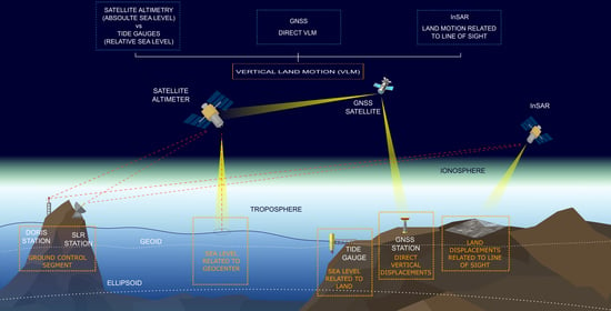
1. Introduction
2. Study Area and Previous Research
3. Data
3.1. InSAR and GNSS
GNSS Data
3.2. Sea-Level Data
4. Integrated VLM Computation Procedures
5. Results and Discussion
6. Conclusions
Author Contributions
Funding
Conflicts of Interest
References
- Lambeck, K. Geophysical Geodesy, the Slow Deformations of the Earth; Clarendon Press: Oxford, UK, 1988. [Google Scholar]
- Hamlington, B.D.; Thompson, P.; Hammond, W.C.; Blewitt, G.; Ray, R.D. Assessing the impact of vertical land motion on twentieth century global mean sea level estimates. J. Geophys. Res. Oceans 2016, 121, 4980–4993. [Google Scholar] [CrossRef]
- Hicks, S.D. Vertical crustal movements from sea level measurements along the east coast of the United States. J. Geophys. Res. 1972, 77, 5930–5934. [Google Scholar] [CrossRef]
- Holdahl, S.R.; Morrison, N.L. Regional investigations of vertical crustal movements in the US, using precise relevelings and mareograph data. Tectonophysics 1974, 23, 373–390. [Google Scholar] [CrossRef]
- Brown, L.D.; Oliver, J.E. Vertical crustal movements from leveling data and their relation to geologic structure in the eastern United States. Rev. Geophys. 1976, 14, 13–35. [Google Scholar] [CrossRef]
- Segall, P.; Davis, J.L. GPS applications for geodynamics and earthquake studies. Annu. Rev. Earth Planet Sci. 1997, 25, 301–336. [Google Scholar] [CrossRef]
- Straub, C.; Kahle, H.G. Active crustal deformation in the Marmara Sea region, NW Anatolia, inferred from GPS measurements. Geophys. Res. Lett. 1995, 22, 2533–2536. [Google Scholar] [CrossRef]
- Dixon, T.H.; Mao, A.; Bursik, M.; Heflin, M.; Langbein, J.; Stein, R.; Webb, F. Continuous monitoring of surface deformation at Long Valley Caldera, California, with GPS. J. Geophys. Res. Solid Earth 1997, 102, 12017–12034. [Google Scholar] [CrossRef]
- Simons, W.J.F.; Ambrosius, B.A.C.; Noomen, R.; Angermann, D.; Wilson, P.; Becker, M.; Vigny, C. Observing plate motions in SE Asia: Geodetic results of the GEODYSSEA project. Geophys. Res. Lett. 1999, 26, 2081–2084. [Google Scholar] [CrossRef]
- Kato, T.; Imae, M.; Sasaki, M.; Murata, M.; Kunimori, H. Application of space techniques to geodesy and geodynamics in Japan. J. Phys. Earth 1995, 43, 629–655. [Google Scholar] [CrossRef]
- Noomen, R.; Springer, T.A.; Ambrosius, B.A.C.; Herzberger, K.; Kuijper, D.C.; Mets, G.J.; Wakker, K.F. Crustal deformations in the Mediterranean area computed from SLR and GPS observations. J Geodyn. 1996, 21, 73–96. [Google Scholar] [CrossRef]
- Soudarin, L.; Crétaux, J.F.; Cazenave, A. Vertical crustal motions from the DORIS space-geodesy system. Geophys. Res. Lett. 1999, 26, 1207–1210. [Google Scholar] [CrossRef]
- Cazenave, A.; Dominh, K.; Ponchaut, F.; Soudarin, L.; Cretaux, J.F.; Le Provost, C. Sea level changes from Topex-Poseidon altimetry and tide gauges, and vertical crustal motions from DORIS. Geophys. Res. Lett. 1999, 26, 2077–2080. [Google Scholar] [CrossRef]
- Nerem, R.S.; Mitchum, G.T. Estimates of vertical crustal motion derived from differences of TOPEX/POSEIDON and tide gauge sea level measurements. Geophys. Res. Lett. 2002, 29, 40-1–40-4. [Google Scholar] [CrossRef]
- Klees, R.; Massonnet, D. Deformation measurements using SAR interferometry: potential and limitations. Geologie Mijnbouw 1998, 77, 161–176. [Google Scholar] [CrossRef]
- Shan, X.J.; Ye, H. The INSAR technique: its principle and applications to mapping the deformation field of earthquakes. Acta Seismol. Sin. 1998, 11, 759–769. [Google Scholar] [CrossRef]
- Wright, T.J.; Parsons, B.E.; Lu, Z. Toward mapping surface deformation in three dimensions using InSAR. Geophys. Res. Lett. 2004, 31, L01607. [Google Scholar] [CrossRef]
- Ferretti, A.; Savio, G.; Barzaghi, R.; Borghi, A.; Musazzi, S.; Novali, F.; Rocca, F. Submillimeter accuracy of InSAR time series: Experimental validation. IEEE Trans. Geosci. Remote Sens. 2004, 45, 1142–1153. [Google Scholar] [CrossRef]
- Fuhrmann, T.; Garthwaite, M.C. Resolving Three-Dimensional Surface Motion with InSAR: Constraints from Multi-Geometry Data Fusion. Remote Sens. 2019, 11, 241. [Google Scholar] [CrossRef]
- Jebur, M.N.; Pradhan, B.; Tehrany, M.S. Detection of vertical slope movement in highly vegetated tropical area of Gunung pass landslide, Malaysia, using L-band InSAR technique. Geosci. J. 2014, 18, 61–68. [Google Scholar] [CrossRef]
- Palanisamy Vadivel, S.K.; Kim, D.J.; Jung, J.; Cho, Y.K.; Han, K.J.; Jeong, K.Y. Sinking tide gauge revealed by space-borne InSAR: Implications for sea level acceleration at Pohang, South Korea. Remote Sens. 2019, 11, 277. [Google Scholar] [CrossRef]
- Song, X.; Jiang, Y.; Shan, X.; Gong, W.; Qu, C. A Fine Velocity and Strain Rate Field of Present-Day Crustal Motion of the Northeastern Tibetan Plateau Inverted Jointly by InSAR and GPS. Remote Sens. 2019, 11, 435. [Google Scholar] [CrossRef]
- Weiss, J.R.; Walters, R.J.; Morishita, Y.; Wright, T.J.; Lazecky, M.; Wang, H.; Yu, C. High-resolution surface velocities and strain for Anatolia from Sentinel-1 InSAR and GNSS data. Geophys. Res. Lett. 2020, 47, e2020GL087376. [Google Scholar] [CrossRef]
- Markušić, S.; Herak, M. Seismic zoning of Croatia. Nat. Hazards 2017, 18, 269–285. [Google Scholar] [CrossRef]
- U.S. Geological Survey. Earthquake Catalog. Available online: https://earthquake.usgs.gov/earthquakes/ (accessed on 14 August 2020).
- Markušić, S.; Ivančić, I.; Sović, I. The 1667 Dubrovnik earthquake–some new insights. Studia Geophys. Geod. 2017, 61, 587–600. [Google Scholar] [CrossRef]
- Pandža Bajs, I. Tourist perceived value, relationship to satisfaction, and behavioral intentions: The example of the Croatian tourist destination Dubrovnik. J. Travel Res. 2015, 54, 122–134. [Google Scholar] [CrossRef]
- Fenoglio-Marc, L.; Dietz, C.; Groten, E. Vertical land motion in the Mediterranean Sea from altimetry and tide gauge stations. Mar. Geodesy 2004, 27, 683–701. [Google Scholar] [CrossRef]
- Garcia, D.; Vigo, I.; Chao, B.F.; Martinez, M.C. Vertical crustal motion along the Mediterranean and Black Sea coast derived from ocean altimetry and tide gauge data. Pure Appl. Geophys. 2007, 164, 851–863. [Google Scholar] [CrossRef]
- Buble, G.; Bennett, R.A.; Hreinsdóttir, S. Tide gauge and GPS measurements of crustal motion and sea level rise along the eastern margin of Adria. J. Geophys. Res. Solid Earth 2010, 115. [Google Scholar] [CrossRef]
- Wöppelmann, G.; Marcos, M. Coastal sea level rise in southern Europe and the nonclimate contribution of vertical land motion. J. Geophys. Res. Oceans 2016, 117. [Google Scholar] [CrossRef]
- Santamaría-Gómez, A.; Bouin, M.N.; Collilieux, X.; Wöppelmann, G. Correlated errors in GPS position time series: Implications for velocity estimates. J. Geophys. Solid Earth 2011, 116. [Google Scholar] [CrossRef]
- Spada, G.; Stocchi, P. SELEN: A Fortran 90 program for solving the “sea-level equation”. Comput Geosci. 2011, 33, 538–562. [Google Scholar] [CrossRef]
- Fenoglio-Marc, L.; Braitenberg, C.; Tunini, L. Sea level variability and trends in the Adriatic Sea in 1993–2008 from tide gauges and satellite altimetry. Phys. Chem. Earth 2012, 40, 47–58. [Google Scholar] [CrossRef]
- Grgić, M.; Nerem, R.S.; Bašić, T. Absolute Sea Level Surface Modeling for the Mediterranean from Satellite Altimeter and Tide Gauge Measurements. Mar. Geodesy 2017, 40, 239–258. [Google Scholar] [CrossRef]
- Amante, C.; Eakins, B.W. ETOPO1 Arc-Minute Global Relief Model: Procedures, Data Sources and Analysis; NOAA Technical Memorandum NESDIS NGDC-24: Washington, DC, USA, 2009.
- Pinter, N.; Grenerczy, G. Recent advances in peri-Adriatic geodynamics and future research directions. In The Adria Microplate: GPS Geodesy, Tectonics and Hazards; Pinter, N., Grenerczy, G., Weber, J., Stein, S., Medak, D., Eds.; Springer: Dordrecht, The Netherlands, 2006; pp. 1–20. [Google Scholar]
- Farolfi, G.; Piombino, A.; Catani, F. Fusion of GNSS and Satellite Radar Interferometry: Determination of 3D Fine-Scale Map of Present-Day Surface Displacements in Italy as Expressions of Geodynamic Processes. Remote Sens. 2019, 11, 394. [Google Scholar] [CrossRef]
- Hanssen, R.F. Radar Interferometry: Data Interpretation and Error Analysis (Vol. 2); Springer Science and Business Media: Amsterdam, The Netherlands, 2001. [Google Scholar]
- Parker, A.L.; Featherstone, W.E.; Penna, N.T.; Filmer, M.S.; Garthwaite, M.C. Practical considerations before installing ground-based geodetic infrastructure for integrated InSAR and cGNSS monitoring of vertical land motion. Sensors 2017, 17, 1753. [Google Scholar] [CrossRef]
- Zerbini, S.; Richter, B.; Rocca, F.; van Dam, T.; Matonti, F. A combination of space and terrestrial geodetic techniques to monitor land subsidence: case study, the Southeastern Po Plain, Italy. J. Geophys. Res. Solid Earth 2007, 112, 1753. [Google Scholar] [CrossRef]
- Delgado Blasco, J.M.; Foumelis, M.; Stewart, C.; Hooper, A. Measuring Urban Subsidence in the Rome Metropolitan Area (Italy) with Sentinel-1 SNAP-StaMPS Persistent Scatterer Interferometry. Remote Sens. 2019, 11, 129. [Google Scholar] [CrossRef]
- Crosetto, M.; Monserrat, O.; Cuevas-González, M.; Devanthéry, N.; Crippa, B. Persistent scatterer interferometry: A review. ISPRS J. Photogramm. Remote Sens. 2016, 115, 78–89. [Google Scholar] [CrossRef]
- Bock, Y.; Wdowinski, S.; Ferretti, A.; Novali, F.; Fumagalli, A. Recent subsidence of the Venice Lagoon from continuous GPS and interferometric synthetic aperture radar. Geochem. Geophy. Geosy. 2012, 13. [Google Scholar] [CrossRef]
- Ferretti, A.; Prati, C.; Rocca, F. Permanent scatterers in SAR interferometry. IEEE Trans. Geosci. Remote Sens. 2001, 39, 8–20. [Google Scholar] [CrossRef]
- Hooper, A.; Bekaert, D.; Spaans, K.; Arikan, M. Recent advances in SAR interferometry time series analysis for measuring crustal deformation. Tectonophysics 2012, 514–517, 1–13. [Google Scholar] [CrossRef]
- Poitevin, C.; Wöppelmann, G.; Raucoules, D.; Le Cozannet, G.; Marcos, M.; Testut, L. Vertical land motion and relative sea level changes along the coastline of Brest (France) from combined space-borne geodetic methods. Remote Sens. Environ. 2019, 222, 275–285. [Google Scholar] [CrossRef]
- Aobpaet, A.; Cuenca, M.C.; Hooper, A.; Trisirisatayawong, I. InSAR time-series analysis of land subsidence in Bangkok, Thailand. Int. J. Remote Sens. 2013, 34, 2969–2982. [Google Scholar] [CrossRef]
- Chaussard, E.; Amelung, F.; Abidin, H.; Hong, S.H. Sinking cities in Indonesia: ALOS PALSAR detects rapid subsidence due to groundwater and gas extraction. Remote Sens Environ. 2013, 128, 150–161. [Google Scholar] [CrossRef]
- Parker, A.L.; Filmer, M.S.; Featherstone, W.E. First results from Sentinel-1A InSAR over Australia: Application to the Perth Basin. Remote Sens. 2017, 9, 299. [Google Scholar] [CrossRef]
- Di Lisa, M.; Ali, H.E.A.; Mazzanti, P.; Moretto, S. Inferring the Creep Settlement Behavior of Rockfill in Reclaimed Lands by Advanced SAR Interferometry and Numerical Modeling: An Example from Arabian Gulf. Remote Sens. 2020, 12, 527. [Google Scholar] [CrossRef]
- Santamaría-Gómez, A.; Bouin, M.N.; Wöppelmann, G. Improved GPS data analysis strategy for tide gauge benchmark monitoring. In Geodesy for Planet Earth; Kenyon, S., Pacino, M.C., Marti, U., Eds.; Springer: Berlin, Germany, 2012; pp. 11–18. [Google Scholar]
- Blewitt, G.; Kreemer, C.; Hammond, W.C.; Gazeaux, J. MIDAS robust trend estimator for accurate GPS station velocities without step detection. J. Geophys. Res. Solid Earth 2007, 121, 2054–2068. [Google Scholar] [CrossRef]
- Wöppelmann, G.; Marcos, M. Vertical land motion as a key to understanding sea level change and variability. Rev. Geophys. 2016, 54, 64–92. [Google Scholar] [CrossRef]
- Holgate, S.J.; Matthews, A.; Woodworth, P.L.; Rickards, L.J.; Tamisiea, M.E.; Bradshaw, E.; Pugh, J. New data systems and products at the permanent service for mean sea level. J. Coast. Res. 2012, 29, 493–504. [Google Scholar] [CrossRef]
- Carrère, L.; Lyard, F. Modeling the barotropic response of the global ocean to atmospheric wind and pressure forcing-comparisons with observations. Geophys. Res. Lett. 2003, 30. [Google Scholar] [CrossRef]
- Andersen, O.B.; Stenseng, L.; Piccioni, G.; Knudsen, P. The DTU15 MSS (mean sea surface) and DTU15LAT (lowest astronomical tide) reference surface. In Proceedings of the ESA Living Planet Symposium 2016, Prague, Czech Republic, 9–13 May 2016. [Google Scholar]
- Scharroo, R.; Leuliette, E.W.; Lillibridge, J.L.; Byrne, D.; Naeije, M.C.; Mitchum, G.T. RADS: Consistent multi-mission products. In Proceedings of the Symposium on 20 Years of Progress in Radar Altimetry, Venice, Italy, 20–28 September 2012. [Google Scholar]
- Vignudelli, S.; Kostianoy, A.G.; Cipollini, P.; Benveniste, J. Coastal Altimetry; Springer: Berlin/Heidelberg, Germany, 2011. [Google Scholar]
- State Geodetic Administration. Geoportal. Available online: https://geoportal.dgu.hr/ (accessed on 18 October 2020).


| Correction Model/Data Used | Data Limits [m] | ||
|---|---|---|---|
| Min | Max | ||
| Orbit | CNES GDR-E | - | - |
| Dry troposphere | ECMWF dry tropospheric correction | −2.40 | −2.10 |
| Wet troposphere | ECMWF wet tropospheric correction | −0.60 | 0.00 |
| Ionosphere | JPL GIM ionospheric correction | −0.40 | 0.04 |
| Atmospheric pressure forcing | MOG2D dynamic atmospheric correction | −1.00 | 1.00 |
| Ocean tide | FES2014b ocean tide | −5.00 | 5.00 |
| Load tide | FES2014b ocean tide | −0.50 | 0.50 |
| Sea state bias | CLS non-parametric sea state bias | −1.00 | 1.00 |
| Reference surface | DTU15 mean sea surface | - | - |
| Standard deviation of range | - | 0.00 | 0.10 |
| Sea-level anomaly | - | −5.00 | 5.00 |
Publisher’s Note: MDPI stays neutral with regard to jurisdictional claims in published maps and institutional affiliations. |
© 2020 by the authors. Licensee MDPI, Basel, Switzerland. This article is an open access article distributed under the terms and conditions of the Creative Commons Attribution (CC BY) license (http://creativecommons.org/licenses/by/4.0/).
Share and Cite
Grgić, M.; Bender, J.; Bašić, T. Estimating Vertical Land Motion from Remote Sensing and In-Situ Observations in the Dubrovnik Area (Croatia): A Multi-Method Case Study. Remote Sens. 2020, 12, 3543. https://doi.org/10.3390/rs12213543
Grgić M, Bender J, Bašić T. Estimating Vertical Land Motion from Remote Sensing and In-Situ Observations in the Dubrovnik Area (Croatia): A Multi-Method Case Study. Remote Sensing. 2020; 12(21):3543. https://doi.org/10.3390/rs12213543
Chicago/Turabian StyleGrgić, Marijan, Josip Bender, and Tomislav Bašić. 2020. "Estimating Vertical Land Motion from Remote Sensing and In-Situ Observations in the Dubrovnik Area (Croatia): A Multi-Method Case Study" Remote Sensing 12, no. 21: 3543. https://doi.org/10.3390/rs12213543
APA StyleGrgić, M., Bender, J., & Bašić, T. (2020). Estimating Vertical Land Motion from Remote Sensing and In-Situ Observations in the Dubrovnik Area (Croatia): A Multi-Method Case Study. Remote Sensing, 12(21), 3543. https://doi.org/10.3390/rs12213543