Article

Multidisciplinary Analysis of Ground Movements: An Underground Gas Storage Case Study

1
Department of Environment, Land and Infrastructure Engineering, Faculty of Engineering, Politecnico di Torino, Corso Duca degli Abruzzi 24, 10129 Torino, Italy
2
Stogit Division, Snam S.p.A., Piazza Santa Barbara 7, 20097 San Donato Milanese, Italy
3
e-GEOS S.p.A., Via Tiburtina 965, 00156 Roma, Italy
*
Author to whom correspondence should be addressed.
Remote Sens. 2020, 12(21), 3487; https://doi.org/10.3390/rs12213487
Submission received: 23 September 2020 / Revised: 16 October 2020 / Accepted: 20 October 2020 / Published: 23 October 2020
(This article belongs to the Special Issue Monitoring Land Subsidence Using Remote Sensing)

Abstract

:
The paper presents a multi-physics investigation of the ground movements related to the cyclical and seasonal injection and withdrawal of natural gas in/from a depleted reservoir located in the Po Plain area, Italy. Interferometric Synthetic Aperture Radar (InSAr) data (from 2003) and Global Navigation Satellite System (GNSS) data (from 2008) provided a full and coherent panorama of almost two decades of ground movement in the monitored area (more extended than the field boundary). The analysis of the acquired millimetric-scale movements together with the detailed geological analysis, both at reservoir and at regional scale, represents the focal point for understanding the investigated phenomena. Based on this information, a fully integrated and multidisciplinary geological, fluid-flow and geomechanical numerical modeling approach was developed to reproduce the main geometrical and structural features of the involved formations together with the poromechanics processes induced by the storage operations. The main achievement of the adopted methodology is a deep knowledge of the system and the involved processes, which is mandatory for the safety of the urbanized areas and the effective management of the underground resources.

1. Introduction

The ground surface movements due to anthropogenic activities, such as underground fluid production/injection, have been deeply investigated by the scientific literature [1,2,3,4], among the others, particularly in potentially critical environments such as high-urbanized areas and costal zones. In the Italian panorama, a large number of hydrocarbon fields were discovered and produced since the early 1950s onward in the Po Plain area (e.g., [5]); due to its high degree of urbanization, the area has been the focus of numerous studies [6,7,8,9,10,11], among others. The monitoring, investigation and forecasting approaches adopted for the subsidence analyses have shown a constant and continuous improvement of the technologies and methodologies to fulfill the higher and higher standards of the system safety and the social acceptance. The ground movement monitoring has improved from Global Navigation Satellite System (GNSS) to Interferometric Synthetic Aperture Radar (InSAR) technologies and the analysis of the involved multiple physical processes has improved from analytical to 3D numerical approaches.
The investigation of ground movements induced by the underground storage of natural gas (UGS) represents a specific branch of the Oil and Gas industry. During UGS activity, natural gas is stored within subsurface geological formations (i.e., depleted hydrocarbon reservoirs, aquifers, salt caverns). The UGS is a worldwide solution adopted to guarantee a real-time response to the market gas requests, a high degree of elasticity in the management of production and transport structures, and the maintenance of “strategic” reserves. Seasonal and cyclical withdrawal and injection of gas induce an alike seasonal and cyclical oscillation (subsidence/rebound) of the ground surface, the so-called “earth breathing” phenomenon [12]. The magnitude and the extension of the phenomenon together with its time of occurrence, depend on a large number of factors including: the withdrawal/injection fluid volume and the induced pressure variation, the presence of surrounding aquifers, the depth, shape and volume of the reservoir formation (and its eventual aquifer) together with its petrophysical parameters, and the geomechanical properties of the reservoir and its surrounding formations [13]. The induced ground oscillation is assimilable to a sinusoidal “signal” which can be discriminated from the background noise; the latter includes the effects of ground water production, thermic and meteoric phenomena, sediment compression due to urban settlements, naturally occurring geological processes, among others. Therefore, the quality and the accuracy of the ground monitoring information can be extremely high if suitable acquisition/interpretation techniques are adopted.
The paper presents a case study concerning the ground movements induced by an UGS field operated in a depleted gas reservoir in the Po Plain area (Northern Italy). A reliable ground movement-monitoring plan via both InSAR and GNSS technologies, and a detailed geological research, at both reservoir and regional scale, provided the key information for the set up and calibration of the geological, fluid-flow and geomechanical numerical models using the Schlumberger Petrel™ software suite. The adopted multidisciplinary simulation approach deeply investigated and reproduced the main geological and structural features of the system together with the fluid-flow and poro-mechanical process related to UGS activities; furthermore, the achieved deep knowledge of the system and the involved processes guarantees the safety of local infrastructures and surrounding environment.

2. Materials and Methods

The aim of the surface monitoring plan was the determination of the planar and vertical components of movement and of the uplift/subsidence area ascribed to UGS operations via two complementary technologies: the satellite SAR interferometry and the GNSS techniques. SAR interferometry investigated an area larger than the field area providing relative measurements of movements whereas GNSS monitoring provided punctual and absolute measurements.
The SAR interferometry is widely used to detect and monitor slow terrain movements with millimeter accuracy along the satellite line of sight (LOS), covering long-term period with frequent updates and large areas with tens of thousands of measurements per square kilometer. The SAR image phase is dependent both on the distance between the radar antenna and the ground target, and on the radiometric characteristics of the transmission medium and of the target. From a stack of interferometric phases (i.e., phase difference between two SAR acquisitions), displacement information of the observed scene is extracted [14] for a set of sparse points (Persistent Scatterers—PSs). The PSs are physical targets characterized by temporally stable backscattering properties and they are commonly found in poorly vegetated and urbanized areas [15,16,17]. The present research was developed according to the Persistent Scatterer Pairs (PSP-IFSAR) approach; it is a multi-interferogram InSAR technique for deriving dense and reliable information in a set of sparse points (PSs). The adopted PSP-IFSAR method, which integrates both ascending and descending acquisition geometries, measures the same ground deformation along two-satellite lines of sight, and, consequently, the actual vertical and East–West planar components of the movements can be determined. The North–South component cannot be derived because the SAR sensors are insensitive to the North–South displacements.
The GNSS (formerly “GPS”) is a space geodetic technique able to determine 3D coordinates of a monitoring permanent site with sub-centimeter accuracy and its over-time kinematic evolution (i.e., its velocity of movement along the planar and vertical components). This geolocation technique is based on more than one constellation of satellites (NAVSTAR for the GPS), numerous ground permanent stations receiving satellite signals and an International GNSS Service (IGS), which ensures high-quality GNSS data products (e.g., GNSS satellite ephemerides, Earth rotation parameters, velocities, etc.). For the present research, the GNSS data were processed using BERNESE software (developed by the Astronomical Institute, University of Berne, Switzerland) [18] through two different approaches (Table 1). The Network Approach adopts about nine reference stations of known coordinates, in addition to the estimating network, in order to set the terrestrial reference frame; the process uses double-differences of the GNSS observables (then a network of stations acquired simultaneously is required). The Precise Point Positioning Approach uses one-way GNSS observables; it does not require a network of stations acquiring simultaneously, but it strictly requires: GNSS data collected by the station to be estimated, precise GNSS orbits, related Earth rotation parameters, corrections for the clocks bias and drift, and specific mapping function for the atmospheric delay modeling (neutral part of the atmosphere).
The acquired and interpreted ground monitoring data were used during the back analysis of the geomechanical modeling, which represents the final step of a complete geological, fluid-flow and geomechanical numerical modeling workflow (Figure 1). The 3D numerical modeling approach was based on a coherent and full dataset, including: 3D seismic survey, primary production and storage data, well-logs, petrophysical and fluid properties; in situ Image log and MDT stress tests, deformation and strength parameters from lab tests, logs and technical literature.
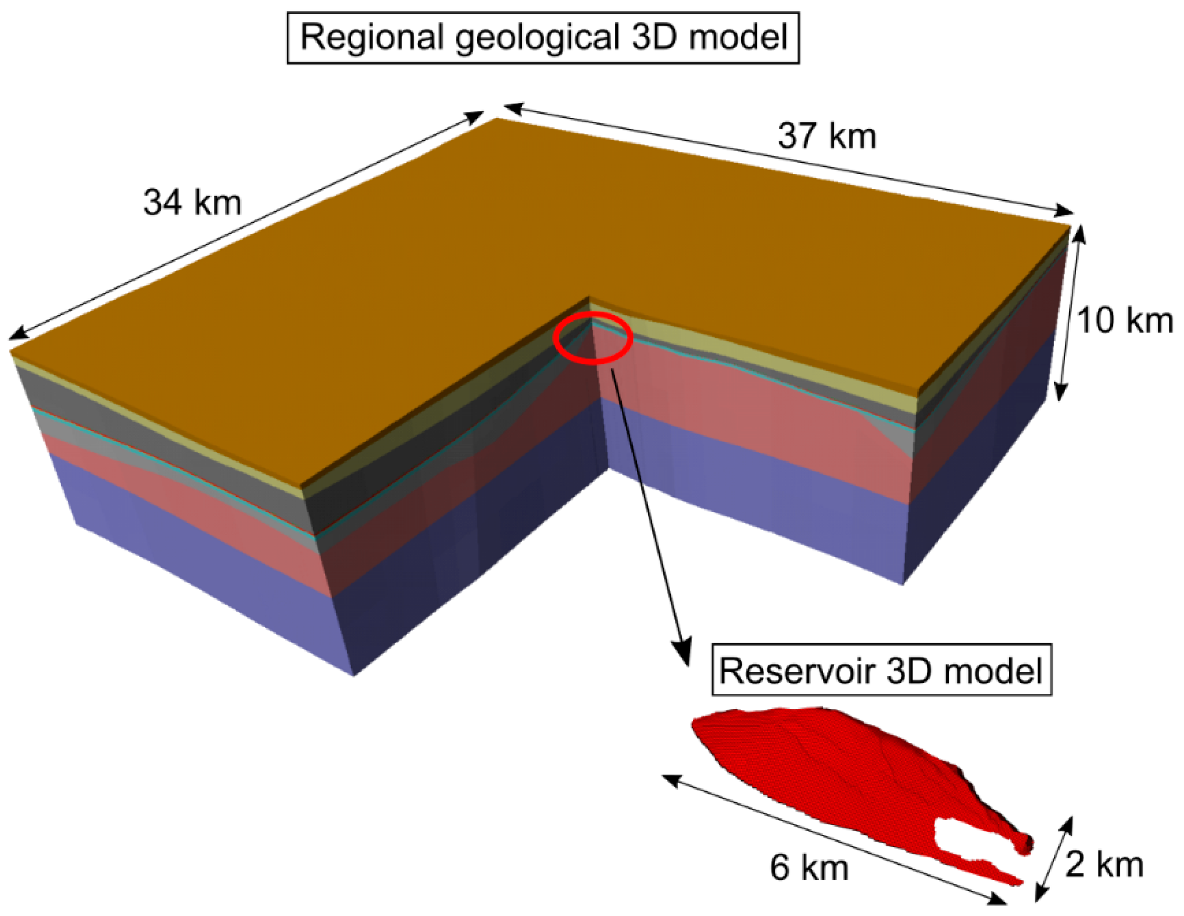
Starting from the detailed reservoir static model, describing all the main stratigraphic, structural, lithological and petrophysical characteristics of the reservoir, an extended (regional-scale) geological model was set up (around 450 103 cells). The latter effectively reproduces the main stratigraphic and structural features of the investigation domain for the ground movement analysis, which includes the reservoir itself and its surrounding formations, up to the surface (Figure 2). A multiphase flow numerical model (FDM) was then set up based on the geological model and on all the available petrophysical and fluid properties together with well completion data. The reservoir consists in sand layers characterized by 18–23% porosity and 100–300 mD (milliDarcy) permeability ranging values; the permeability anisotropy at the reservoir scale reflects the occurrence of pelitic interlayers within the reservoir. The model was then initialized and calibrated to reproduce the pressure distribution in the reservoir during more than 60 years of production and storage history, considering data from 80+ wells. The pressure distribution in the reservoir is homogeneous as the reservoir has no internal compartmentalization; the cyclical pressure variations follow the cyclical gas storage volume variations that were compared with the ground movement measures during the InSAR and GNSS analyses. The dynamic model is periodically updated at the end of each injection/withdrawal phase as new pressure data are acquired from the monitoring wells.
Finally, the ground displacement analysis was addressed via a stress–strain finite element (FEM) model, set up based on the extended geological study. The model was characterized by mechanical properties derived from lab and log data (Table 2). During the initialization phase, the initial pore pressure distribution and the original stress state were defined for all the investigated volumes according to the available data (i.e., initial static pressure, well logs and in situ tests). Dirichlet boundary conditions were imposed (i.e., zero displacement on the lateral and bottom boundaries, zero normal stress on the surface). Rock mechanics engineering analyses were developed according to the elastic-purely plastic constitutive law and adopting the Mohr–Coulomb failure criteria. As a matter of fact, different studies focused on ground subsidence induced by UGS for analogous case studies have shown the reliability of the elastic constitutive model in simulating the measured surface movement data [19,20,21]. It should be taken into consideration that the UGS-related pressure variations affect the formation both cyclically (following the withdrawal/injection phases) and in a very small time frame (5/6 moths): it clearly differs from a standard monotonic pressure decrease over some decades that typically characterizes the primary production, and the formations react accordingly. On the base of the preliminary sensitivity analysis results, the model of the case under study reacted within the elastic domain even at the end of primary production when the system experienced the maximum pressure variation. An adequate time stepping was set up accordingly for the UGS system analysis: the mechanical simulations were performed at the end of the primary production, and at the end of each production/injection period for all the InSAR monitoring time frames. Furthermore, a negligible variation of the petrophysical parameters due to pressure change was expected, in agreement with other UGS in analogous clastic formations studies [7,11,21]. Consequently, an uncoupled fluid-flow and stress–strain approach was adopted: the time and space pressure evolution represents the forcing function applied to the geomechanical model, whereas the petrophysical parameter values adopted in the fluid-flow model remain unchanged. The historical pressure evolution and the vertical ground displacement data were finally integrated in the numerical model via a back analysis approach: the adopted pseudo-elastic parameters of the reservoir and of the cap rock were fine-tuned to achieve a suitable match between simulated and measured movements. Previous experiences of the authors and the technical literature (please consider the abovementioned references) highlighted that the UGS-related ground movements for a clastic reservoir at about 1000-1500 m depth, placed in the specific geological contest under analysis (paragraphs 3.1 and 3.2), are mainly influenced by the stress–strain behavior of the gas bearing formations and, secondly, by the stress–strain behavior of the cap rock.

3. Results

3.1. Regional Geological Setting

A deep knowledge of the geological characteristics of the examined formations is fundamental for the construction of accurate and representative 3D geological models and for the interpretation of ground monitoring data. Regarding the case study, a detailed geological analysis was developed at both reservoir and regional scales and it provided insight of the internal stratigraphic–structural architecture and of the heterogeneity of the investigated volume.
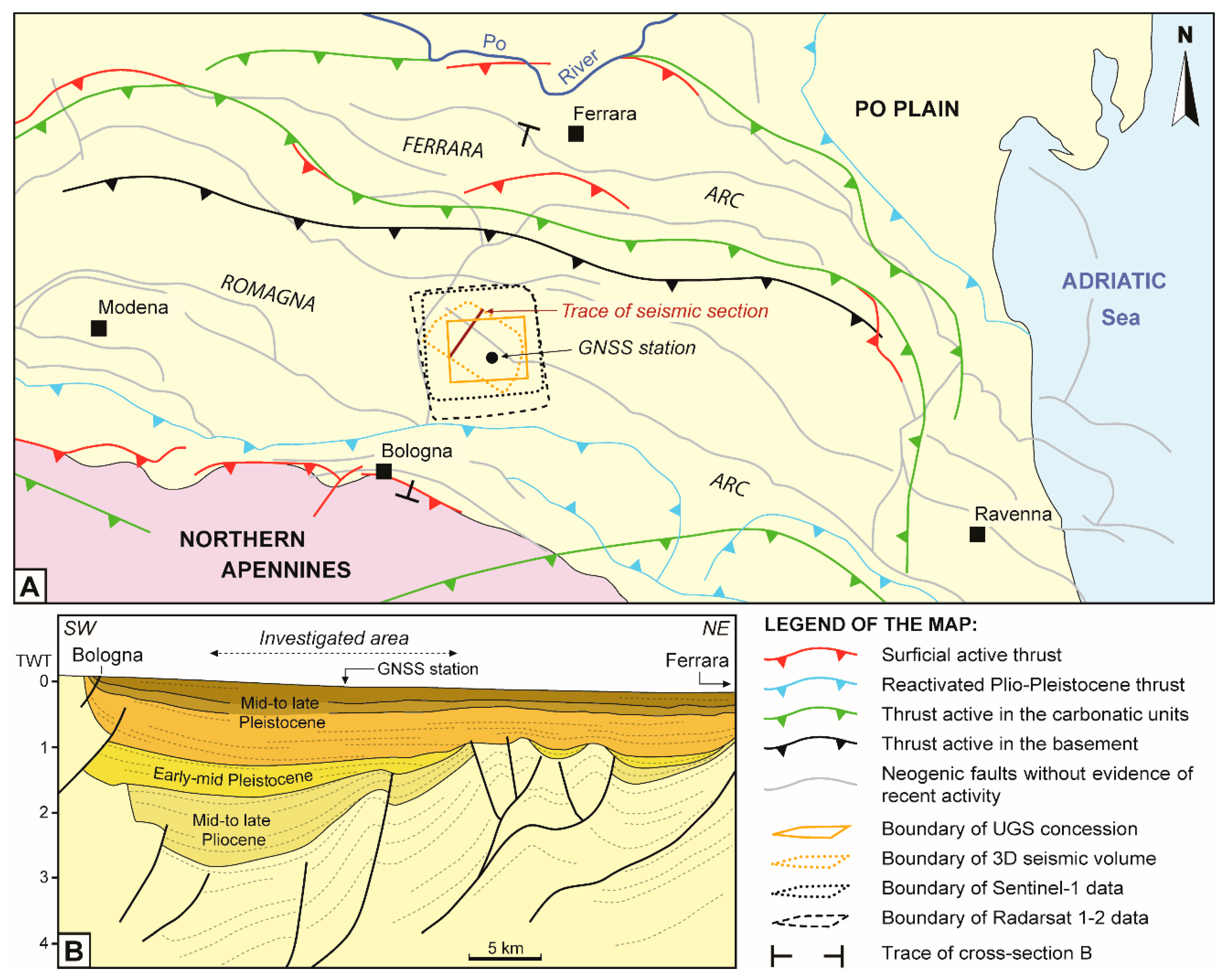
The studied UGS field is placed in the eastern Po Plain (North of Italy) (Figure 3). The Po Plain-Northern Adriatic region was extensively studied through exploration well data and 2D-3D seismic surveys acquired over the last 40 years (e.g., [22,23,24,25]). During Jurassic–Triassic time the region experienced east-west directed extensional phases which led to the formation of fault-bounded basins (e.g., [23,26]). In response to the subsequent Eurasia–Adria plate convergence, the rift-related framework was overprinted by Cenozoic compressional structures that are currently buried below the Po Plain sedimentary infill. The present-day architecture of the Po Plain is mainly the result of the Late Messinian–Pleistocene tectonic evolution; the latter led to the development of the Po Plain-Adriatic basin as a shared, complex foredeep separating the converging Southern Alpine (to the north) and Northern Apennine (to the south) chains, which locally collided in the Po Plain subsurface (e.g., [27,28]).
The buried Northern Apennines is an arc-shaped fold-and-thrust belt subdivided into three adjoining arcs named Monferrato, Emilia and Ferrara-Romagna arcs (from the west to the east, respectively) [29]. Its subsurface architecture consists of synclines and ramp anticlines associated with blind thrusts formed in response to a series of successive tectonic pulses that have led to the progressive North-Northeastward migration of the outermost thrust fronts (Figure 3). During the latest Miocene–Pliocene event, the eastern Po Plain has undergone a strong tectonic activity; the Late Pliocene–Pleistocene tectonic events led to the complete development of the outer fold and thrust system of Ferrara and to the uplift and tilting of the Bologna area [24]. The area of the UGS field is characterized by NE-verging, arcuate blind thrusts which involved the Mesozoic units, their pre-Mesozoic basement and the younger clastic infill of the Plio-Pleistocene foredeep (Figure 3). In the field area there is no evidence of the presence of thrusts dislocating the Pleistocene sediments or with reactivations during the Late Pliocene–Pleistocene times: none of the thrusts that created significant dislocation of the pre-Pliocene sequences propagated across the base of the Early Pleistocene deposits (e.g., [25,30,31]).
The Pliocene foredeep infill in the UGS field area includes the thick syntectonic, sand turbidites of the Porto Corsini Fm. (Early-Middle Pliocene) and Porto Garibaldi Fm. (Middle-Late Pliocene); meanwhile, the clay sequence of the Santerno Fm. (Pliocene–Early Pleistocene) was deposited above the submarine paleo-highs and part of the foreland and foreland ramp. Finally, the late Pliocene–Pleistocene sedimentary infill recorded the gradual transition from deep-marine to continental environment (i.e., Asti Group), through the development of the basin-scale Po Plain prograding complex as a result of the east-ward progradation of the Po River delta. The overall Plio-Quaternary clastic sequence reaches a thickness of about 7-8 km in the deepest depocentral areas of the basin [22,24,32].

3.2. UGS Gas Field Description

The investigated gas field is located approximately 20 km NE of the Bologna city (Figure 3) at an average depth of 1300 m ssl. The gas primary production started in 1956 and, after two decades, the reservoir was converted into a gas storage system. Currently the system is managed at a maximum injection pressure close to the initial pressure of the reservoir with injection and production rates in the order of 3 to 25 MSm3/d and 5 to 40 MSm3/d, respectively; 50+ wells were drilled on the trap culmination for the storage operations and pressure monitoring.
The reservoir consists of a mixed (stratigraphic–structural) trap that combines an asymmetric anticline controlled by an NE-verging, blind thrust and the deposition of sandy levels onlapping on the structural high with local pinching-out features. The pinch-out closure over the structural high defines a non-deposition area in the SE part of the field. Minor, extensional faults, sub-parallel to the trap axis, affect the axial area. Neither the stratigraphic nor the structural features produced reservoir compartmentalization.
The reservoir sequence belongs to the Porto Garibaldi Fm. (Middle-Late Pliocene) and consists of an alternance of sand layers, meter-to-decameter thick, and clay layers, 1 to 10 m of average thicknesses. The caprock consists of clay and silty-clay of the upper member of the Santerno Fm.; the latter covers the entire reservoir area with an average thickness of 130 m ensuring the complete seal of the gas trap. Downward, the Porto Garibaldi Fm. is separated from the Porto Corsini Fm. (Early-Middle Pliocene) by the Santerno Fm. lower member.
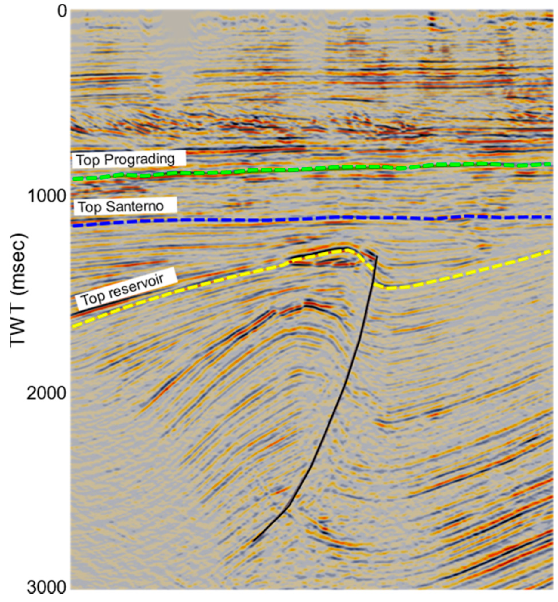
In 2011, a 3D seismic survey was acquired and processed covering the entire UGS area (Figure 3). The approximate extension of the acquisition was 11.5 km × 7 km and the investigation depth almost 12 km. The results were integrated and interpreted together with data from the existing wells. The cross-section derived from the 3D seismic volume shown in Figure 4 highlights the geometry of the trap and of the main thrust bounding the reservoir to the North. The three main marker surfaces here represented correspond to the Top reservoir (Late Pliocene), Top Santerno (Calabrian, i.e., Early Pleistocene) and Top Prograding (Middle Pleistocene). The seismic data show that the thrust that bounds the trap ends within the Santerno Fm. without reaching the Top Santerno horizon and thus not affecting the Quaternary sequence as well as none of the faults inside the seismic volume. According to the literature, it confirms the absence of evidence of recent reactivation for the Neogenic faults present in the investigated area.

3.3. Ground Surface Monitoring Results

3.3.1. SAR interferometry results

The huge archive of InSAR data (C-band) (Table 3) was analyzed via the PSP-IFSAR technique. Radarsat-1/2 data have provided a very long series of ground displacement measurements starting from 2003 with a temporal resolution of 24 days in both observation geometries. Starting from 2014, Sentinel-1 data have provided more detailed information on the last 5 years with a new acquisition every 6 days in both observation geometries. The satellite data cover an area larger than the field area, as shown in Figure 3.
Based on ascending and descending results, for each sensor, the vertical and East–West planar movements were derived. The PSP measurements of the ground movement at each acquisition date allowed the evaluation of its mean velocity (as linear trend between the first and the last acquisition of each interferometric stack) and its mean amplitude (in case of sinusoidal behavior).
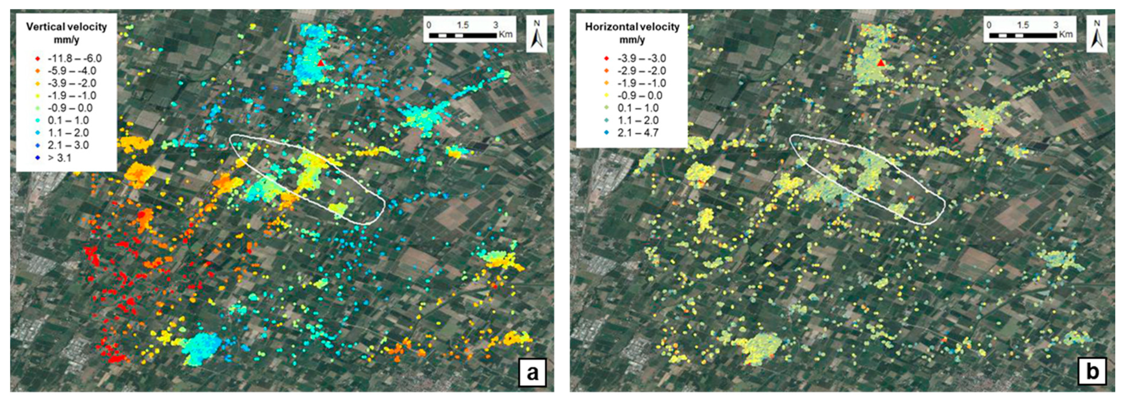
The mean velocity data show the overall stability of the field area with a slight subsidence trend; local zones with slight uplift or subsidence are evident in the vertical velocity map, with a notable subsidence phenomenon in the South–West area towards the city of Bologna (Figure 5). The mean vertical velocity in the area above the field ranges between −1.0 and −2.0 mm/year. The sub-millimetric difference between the Radarsat and Sentinel results can be attributed to the different time spans they investigated (2003–2019 vs. 2015–2019, respectively).
Figure 6 shows the Radarsat maps of the mean vertical and horizontal amplitude of the ground displacement. The well-defined area of maximum vertical amplitude is located above the center of the UGS field (Figure 6a) and it coincides with the area of minimum horizontal amplitude (Figure 6b). Instead, the areas of the maximum horizontal amplitude identify two isolated peaks in the East–West direction around the center of the reservoir; zero amplitude values are detected along the North–South direction because of the limit of the InSAR technique.
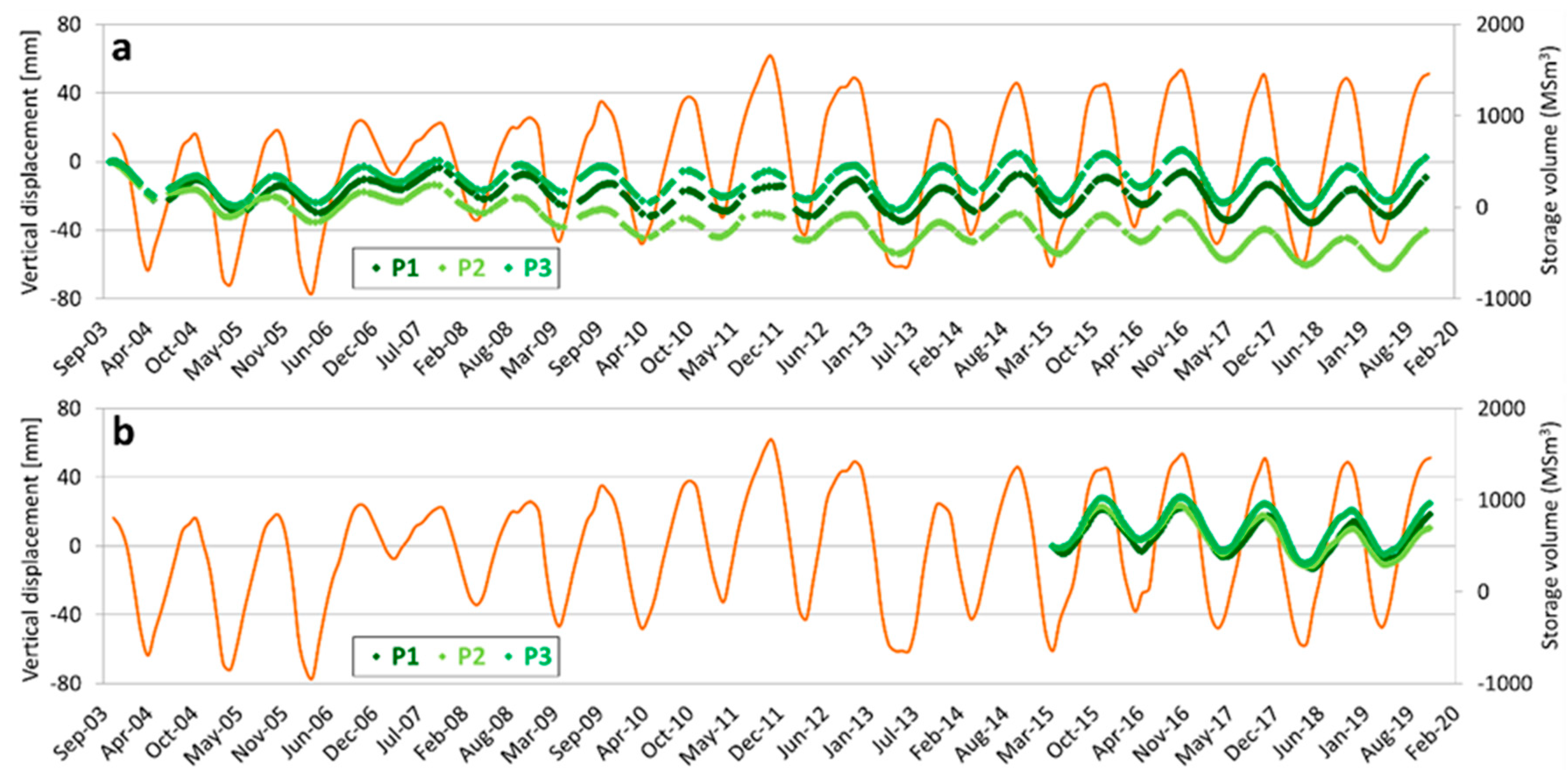
Six representative points were selected in the InSAR-monitored area within and outside the field boundary (Figure 6a): their historical displacement along the vertical and the East–West directions were compared with the curve of the storage gas cumulative volumes of the whole field. The temporal evolution of the two ground displacement components for the P1, P2, P3 internal points shows a clear sinusoidal signal with a strong correlation with the trend of the gas cumulative volume curve in terms of amplitude and periodicity (Figure 7 and Figure 8). The vertical displacement always shows the maximum and minimum peaks at the end of each injection and withdrawal period, respectively, with a delay of about 30 days, which could be attributed primarily to fluid-flow phenomena (i.e., time and space propagation of the pressure sink in the reservoir and surrounding aquifer) (Section 2. Materials and Methods).
The horizontal displacement shows alike clear sinusoidal signals: during the withdrawal periods P1-P2 points show positive trends (i.e., eastward direction) and P3 point shows negative trend (i.e., westward direction); vice versa, during the injection periods, P1-P2 points show negative trends and P3 point shows a positive one. The divergent responses can be attributed to the different locations of the points in respect to the area of maximum vertical displacement (i.e., reservoir center). The time series of the points outside the field area (P4, P5, P6) show displacement trends, oscillation characteristics and periodicity, both in vertical and horizontal directions, unrelated with the storage activity (Figure 9 and Figure 10).
Note that the Radarsat series are more sensitive to the long-term displacement trends whereas Sentinel series give a higher detail on the last monitoring years because of the different monitored time spans. The time series of the vertical displacement confirm a long-term trend of gentle surface downwarping in the field area.

3.3.2. GNSS results

The permanent GNSS station was installed at the end of 2008 in the area of the storage plant located at the south-eastern edge of the gas field (Figure 3 and Figure 6). The station was equipped with an ASHTECH UZ-12 receiver since the installation date in 2013, when it was replaced by a LEICA GR10 receiver. The GNSS antenna is a TOPCON, TPSCR4 model, with TPSH radome, dual frequency GPS (L1/L2).
The daily RINEX data of the GNSS permanent station were analyzed via the TEQC software (http://facility.unavco.org/software/teqc), an international standard for the pre-processing phase of GPS data and for the evaluation of their quality. The data quality was stated by using the TEQC parameters MP1 (multipath on L1) and MP2 (multipath on L2). Based on the values of the IGS reference stations, the values of MP1 (<0.5 m) and MP2 (<0.75 m) indicate a good quality station (Figure 11).
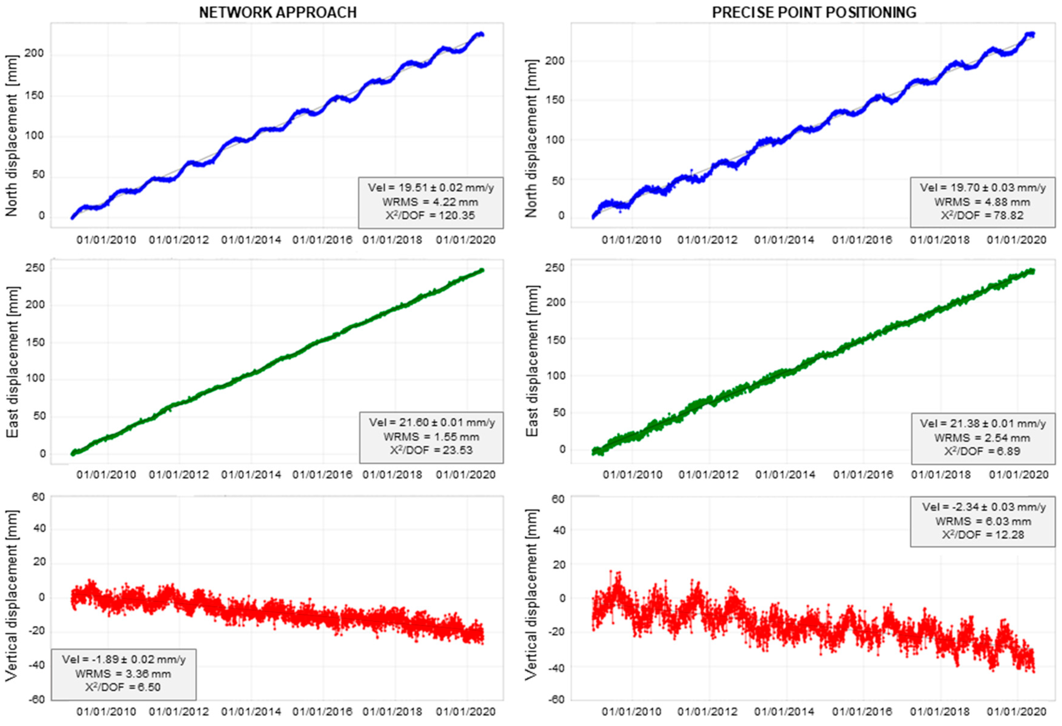
The results of the two processing approaches, the Network Approach and the Precise Point Positioning, are reported in Figure 12 in terms of coordinates time series: their consistency attests the robustness of the results. The areal and vertical trends of displacement indicate a marked NE-ward movement and a gentle subsidence of the monitored site, respectively.
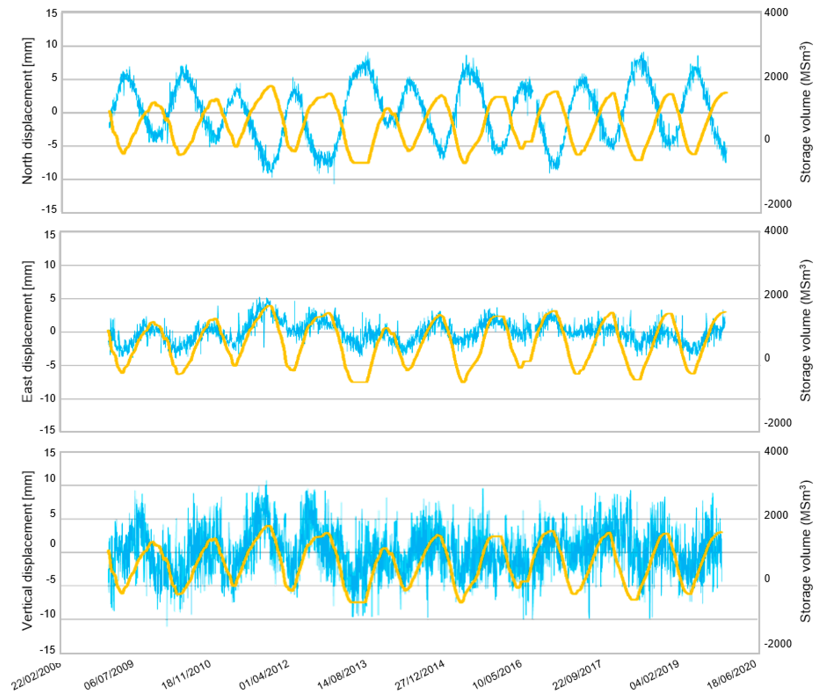
In order to discriminate the effects of the UGS activities along the three components of displacement, the signals ascribed to other known phenomena were removed. The typical seasonal signals of the GNSS time series are essentially due to load variations caused by the redistribution of fluid masses on the Earth’s surface, (e.g., [33]). It includes changes in air mass, which results in changes in surface air pressure, in ocean level due to terrestrial and solar tides, wind and pressure atmospheric, and, above all, in soil moisture (surface hydrological load). Once removed the long-term velocity from the GNSS time series, the residual time series were obtained. The latter were compared with the displacements due to changes in the surface hydrological load (the so-called “surface hydrological mass loading”) by using the data of the EOST Loading Service (http://loading.u-strasbg.fr/) and the data estimated by MERRA2 [34]. The seasonal vertical movement recorded by the GNSS station is largely due to the variation in the hydrological load (the hydrological model well followed the analytical seasonal model) and does not show an appreciable displacement-UGS correlation. On the contrary, the hydrological model does not explain the seasonal shifts observed in the planar components, attributed to the UGS activity (Figure 13). The two horizontal displacement components are seasonally dependent: during withdrawal periods the North–South component shows a positive trend (i.e., northward direction), and the East–West component shows a negative trend (i.e., westward direction), in agreement with the movement toward the peak of the maximum vertical displacement highlighted by InSAR data. On the contrary, during injection periods, the North–South component shows a negative trend, and the East–West component a positive trend. Furthermore, the main direction of planar movement is almost North–South (about N198°).

3.4. Geomechanical Simulation Results

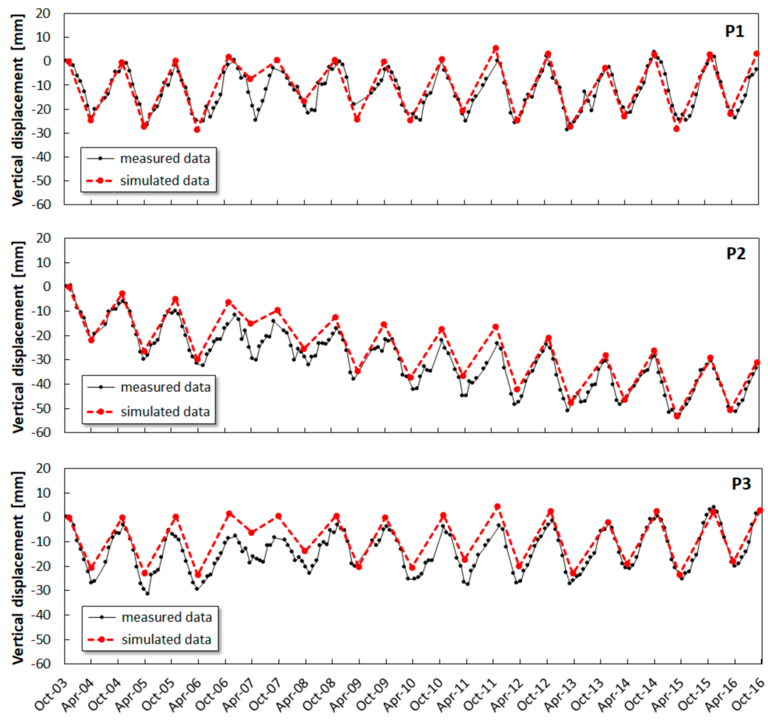
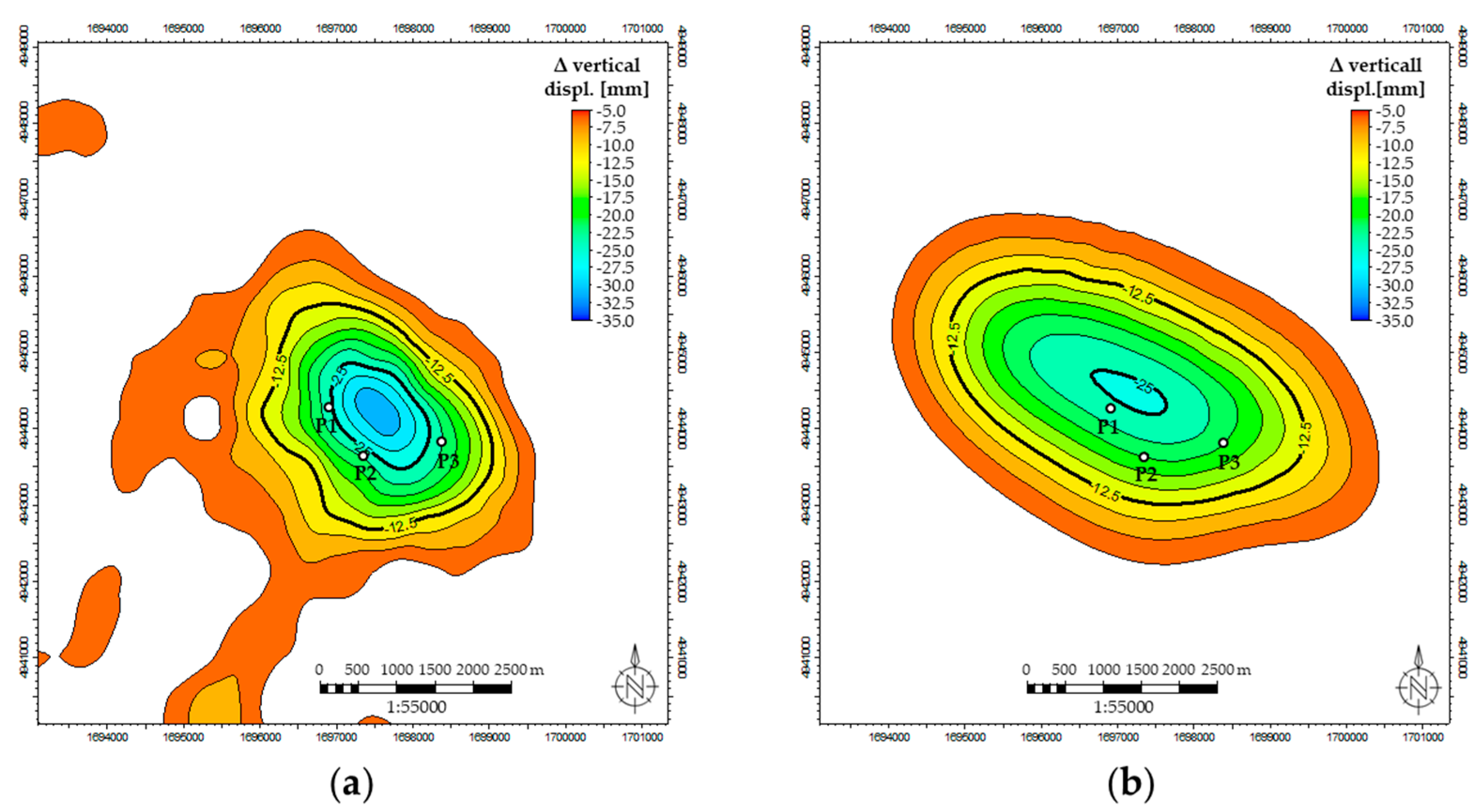
In the back-analysis phase of the mechanical model, the calibration of the pseudo-elastic parameters of the reservoir and the cap rock allowed a suitable match between the simulated vertical ground movements and the measured values discussed in the previous paragraph. Radarsat data were considered because of their longer period of acquisition. Figure 14 shows the comparison between simulated and measured values, in terms of relative variations within a single withdrawal/injection cycle, for the three points placed at surfaces within the boundary of the field (location in Figure 6) during a monitored time frame. For P2 point, a descending trend recognized by InSAR analysis, and not ascribable to UGS operations, was superimposed to the simulation results. The analysis of the InSAR data allowed the identification also of the areal extension of the ground surface cyclically affected by the UGS activities: Figure 15 shows an example of comparison between measured and simulated delta displacement maps at surface level, for a historical withdrawal period during UGS activity.

4. Discussion

4.1. Ground Monitoring Data and Comparison with UGS

Since 1950s, the eastern Po Plain area, where the studied field is located, has been experiencing a widespread and strong subsidence mainly due to anthropic causes, with a minor contribution (of a few mm/year) from ongoing natural processes (e.g., tectonics, sediment consolidation) [8,35,36]. In particular, the subsidence evolution in this region mostly depended on the groundwater pumping [8]. This phenomenon was particularly relevant in the Bologna area, where a subsidence rate in the order of several cm/year was historically measured; subsequently, the impressive subsidence reduction monitored during recent decades was a direct result of the reduction in groundwater pumping activities [36].
The huge spatial and temporal extension of the InSAR monitoring allowed the investigation, not only of the UGS field area but also of the surroundings; it ensured the consistency of the measured displacements with respect to regional trends over a large time span. The analysis and interpretation of the InSAR data have showed that:
(i)
the field area is characterized by a general long-term, gentle subsidence trend with no uplift evidence above the blind thrust, potentially ascribable to the growth of the buried anticline; a pronounced subsidence occurs in the direction of the Bologna city, outside the field area;
(ii)
the UGS activity does not affect the mean horizontal and vertical displacement velocities in the gas field area, which are coherent with the velocity range within the entire monitored domain;
(iii)
a strong correlation exists between the curve of the storage gas cumulative volumes and the historical series of the ground displacement above the reservoir, considering both the vertical and East–West planar components;
(iv)
the UGS-related, short-term, cyclical subsidence/uplift is limited to the field area; it is maximum in the center of the area while it dissipates near the field boundary.
The analysis and interpretation of the GNSS data have showed that:
(i)
the GNSS site is characterized by a long-term, gentle subsidence trend, in agreement with InSAR data;
(ii)
the estimated areal velocities are consistent with the NE-ward vergence of the Northern Apennines driven by the movement of the Eurasiatic plate (e.g., [35]);
(iii)
The short-term, seasonal vertical displacement of the GNSS station (placed close to the field boundary) is largely due to the variation in hydrological load rather than the UGS activities, resulting in the absence of an appreciable correlation between the curve of the storage gas cumulative volumes and the residual sinusoidal trend. The GNSS response is coherent with InSAR data, which show the decrease in the UGS-related cyclical vertical displacement towards the field boundary;
(iv)
a strong correlation exists between the UGS activities and the short-term, seasonal horizontal displacements; in particular, the GNSS station is more sensitive to the North–South planar component of movement due to its location at the south-eastern edge of the gas field area.
In conclusion, the integration between GNSS and InSAR data provides a full and coherent panorama of the ground movement in the monitored area.
Note that the present analysis investigated the effects of the storage activities and did not deeply analyze other variables such as seasonal temperature variations, groundwater withdrawal or large-scale natural subsidence/uplifting.

4.2. Discussion about the Geomechanical Simulation Results

The pseudo-elastic parameters adopted for the mechanical characterization of the reservoir and the cap rock were derived from laboratory tests (triaxial compression tests under isotropically consolidated undrained conditions), from the interpretation of well logs (sonic and density logs) and corroborated by data from the technical literature. The obtained Young’s modulus values differ by almost one order of magnitude: from few GPa (values from the lab data interpretation) to 8–10 GPa (values from the log data interpretation). As documented by analogous case studies reported in the technical literature [11,19], the mechanical behavior of clastic formations at a depth of around 1000–1500 m ssl could exhibit an important (non-linear) influence of the strain on the formation stiffness, especially in case of soft rocks [37,38]. Experimental values of the deformation parameters (i.e., Young’s modulus) increase as the imposed strain levels decrease from small strain (i.e., the values obtained from the stress–strain measurements in a rock mechanical test) to very small strain (i.e., values obtained from the interpretation of acoustic acquisition) [39,40]. Furthermore, if acoustic acquisitions are available at wellbore level, the scale effect can also be taken into consideration.
The discrepancy in the experimental values could generate uncertainty in defining the real deformation behavior of the formations; it is trivial to say that high variability of input parameters leads to high uncertainty in model prediction.
For the investigated case study, the real deformation behavior of the formation was identified via the back-analysis of the mechanical model. The formation stiffness that resulted from the calibration process is around three times higher than the values from lab tests, in agreement with the lithologies under analysis and with the in-situ stress condition during UGS operations [11,19]. As a theoretical explanation, during primary production, the deformation behavior of the normally consolidated formations is controlled by the loading static elastic modulus EI (in the case presented in this paper, EI are the values obtained from the lab tests). In this phase, the stress–strain path follows the critical state line (CSL). Due to the formation compaction caused by storage activities, the formations could become slightly over-consolidated and their elastic deformation response during the storage phase is usually ruled by the unloading/reloading static elastic modulus EII, around 2-4 times higher than EI.
The good match obtained between measured and simulated ground displacements assuming a constant unloading/reloading elastic modulus over almost two decades of UGS operation denotes a sound and stable system response in time.
Once calibrated, the geomechanical model represents an effective tool for forecasting future scenarios.

5. Conclusions

The paper proposes a fully-integrated and multi-physics approach for the analysis of the ground movement related to a gas storage system (eastern Po Plain area). The gas field is hosted in a clastic Pliocene sequence involved in a mixed trap. The trap combines the onlap of sand levels and a structural high associated with an NE-verging blind thrust that ends within the Pliocene sequence without propagating up to the Quaternary clastic sequence. The InSAR data excludes surface evidence of an active growth of the buried anticline during the entire monitored period.
The monitoring of the ground movements was achieved via both the SAR interferometry (PSP-IFSAR) and the GNSS continuous technologies. The two complementary technologies provided quantitative information about vertical and planar (North–South and East–West) components of the surface movements (with millimetric accuracy) and the subsidence/uplift areal extension of the UGS influence. The InSAR data measured the East–West planar and vertical components; the robustness of the adopted methodology is attested by the use of two different sensors (Radarsat-1/2 and Sentinel-1) to get independent and independently processed measures, and by the consistency of the results. On the other hand, the GNSS station measured the punctual displacement component associated with the UGS activity along the North–South direction, missed by the InSAR acquisition. The information from GNSS and InSAR data provided a full and coherent panorama of the ground movement in the monitored area: in particular, the identification of a regional trend was used for interpreting the effects of UGS operation.
The reliable ground movement monitoring plan and the detailed geological analysis, both at reservoir and regional scales, are key information for the geological, fluid-flow and geomechanical numerical simulation process. The multidisciplinary simulation approach deeply investigated and reproduced the main geological and structural features of the system together with the fluid-flow and poro-mechanical processes induced by UGS activities. In particular, almost two decades of displacement data effectively supported the calibration process of the geomechanical model, which showed a sound and stable mechanical response of the system in terms of induced subsidence/uplift for a given variation of pressure.
Furthermore, the two calibrated dynamic and geomechanical models represent the most reliable tool in forecasting the performance and in verifying the safety of the UGS system under different management conditions.

Author Contributions

All authors collaborated for the preparation of the original draft and on revising the manuscript; A.M., C.B., G.C., G.T., V.R. proposed the main structure of this study; F.T., A.M., G.C. dealt with InSAR data analysis, C.F., A.M. dealt with GNSS data analysis, C.B., G.T. dealt with seismic data analysis, G.C., V.R. dealt with geomechanical analysis. All authors have read and agreed to the published version of the manuscript.

Funding

This research received no external funding.

Acknowledgments

The authors would like to express their gratitude to two anonymous reviewers for their comments and suggestions that considerably improved the manuscript.

Conflicts of Interest

The authors declare no conflict of interest.

References

  1. Poland, J.F.; Davis, G.H. Land Subsidence Due to Withdrawal of Fluids. Rev. Eng. Geol. 1969, 2, 187–270. [Google Scholar] [CrossRef]
  2. Settari, A.; Walters, D.A.; Stright, D.H.; Aziz, K. Numerical Techniques Used for Predicting Subsidence Due to Gas Extraction in the North Adriatic Sea. Pet. Sci. Technol. 2008, 26, 1205–1223. [Google Scholar] [CrossRef]
  3. Rutqvist, J.; Vasco, D.W.; Myer, L.R. Coupled reservoir-geomechanical analysis of CO2 injection and ground deformations at In Salah, Algeria. Int. J. Greenh. Gas Control. 2010, 4, 225–230. [Google Scholar] [CrossRef] [Green Version]
  4. Giani, G.; Orsatti, S.; Peter, C.; Rocca, V. A Coupled Fluid Flow—Geomechanical Approach for Subsidence Numerical Simulation. Energies 2018, 11, 1804. [Google Scholar] [CrossRef] [Green Version]
  5. Casero, P. Structural setting of petroleum exploration plays in Italy. In Italian Geological Societ Special Volume for the 32nd IGC, 20–28 August 2004, Florence, Italy; Società geologica italiana (Italian Geological Society): Rome, Italy, 2004; pp. 188–189. [Google Scholar]
  6. Baú, D.; Gambolati, G.; Teatini, P. Residual land subsidence near abandoned gas fields raises concern over northern Adriatic coastland. EOS Trans. Am. Geoph. Union 2000, 81, 245. [Google Scholar] [CrossRef]
  7. Baú, D.; Ferronato, M.; Gambolati, G.; Teatini, P. Basin-scale compressibility of the northern Adriatic by the radioactive marker technique. Geotechnique 2002, 52, 605–616. [Google Scholar]
  8. Teatini, P.; Ferronato, M.; Gambolati, G.; Gonella, M. Groundwater pumping and land subsidence in the Emilia-Romagna coastland, Italy: Modeling the past occurrence and the future trend. Water Resour. Res. 2006, 42, 01406. [Google Scholar] [CrossRef]
  9. Dacome, M.C.; Miandro, R.; Vettorel, M.; Roncari, G. Subsidence monitoring network: An Italian example aimed at a sustainable hydrocarbon E&P activity. In Proceedings of the International Association of Hydrological Sciences (IAHS), Nagoya, Japan, 15–19 November 2015; Copernicus GmbH: Göttingen, Germany, 2015; Volume 372, pp. 379–384. [Google Scholar] [CrossRef] [Green Version]
  10. Benetatos, C.; Codegone, G.; Deangeli, C.; Giani, G.; Gotta, A.; Marzano, F.; Rocca, V.; Verga, F. Guidelines for the Study of Subsidence Triggered by Hydrocarbon Production; GEAM—Geoingegneria Ambientale e Mineraria Anno LIV: Turin, Italy, 2017; Volume 3, pp. 85–96, ISSN 11219041. [Google Scholar]
  11. Coti, C.; Rocca, V.; Sacchi, Q. Pseudo-Elastic Response of Gas Bearing Clastic Formations: An Italian Case Study. Energies 2018, 11, 2488. [Google Scholar] [CrossRef] [Green Version]
  12. Castelletto, N.; Ferronato, M.; Gambolati, G.; Janna, C.; Teatini, P.; Marzoati, D.; Cairo, E.; Colombo, D.; Feretti, A.; Bagliani, A.; et al. 3D geomechanics in UGS projects. A comprehensive study in Northern Italy. In Proceedings of the 44th US Rock Mechanics Symposium and 5th U.S.—Canada Rock Mechanics Symposium, Salt Lake City, UT, USA, 27–30 June 2010; pp. 27–30. [Google Scholar]
  13. Fjær, E.; Holt, R.; Horsrud, P.; Raaen, A.; Risnes, R. Chapter 3 Geological aspects of petroleum related rock mechanics. In Developments in Petroleum Science, 2nd ed.; Elsevier BV: Amsterdam, The Netherlands, 2008; Volume 53, pp. 103–133. [Google Scholar]
  14. Costantini, M.; Falco, S.; Malvarosa, F.; Minati, F.; Trillo, F. Method of persistent scatterer pairs (PSP) and high resolution SAR interferometry. In Proceedings of the 2009 IEEE International Geoscience and Remote Sensing Symposium (IGARSS ’09), Cape Town, South Africa, 12–17 July 2009; Volume 3, pp. 904–907. [Google Scholar]
  15. Costantini, M.; Malvarosa, F.; Minati, F.; Vecchioli, F. Multi-scale and block decomposition methods for finite difference integration and phase unwrapping of very large datasets in high resolution SAR interferometry. Geosci. Remote Sens. Symp. IEEE Int. 2012, 5574–5577. [Google Scholar] [CrossRef]
  16. Costantini, M.; Malvarosa, F.; Minati, F. A General Formulation for Redundant Integration of Finite Differences and Phase Unwrapping on a Sparse Multidimensional Domain. IEEE Trans. Geosci. Remote Sens. 2011, 50, 758–768. [Google Scholar] [CrossRef]
  17. Costantini, M.; Falco, S.; Malvarosa, F.; Minati, F.; Trillo, F.; Vecchioli, F. Persistent Scatterer Pair Interferometry: Approach and Application to COSMO-SkyMed SAR Data. IEEE J. Sel. Top. Appl. Earth Obs. Remote Sens. 2014, 7, 2869–2879. [Google Scholar] [CrossRef]
  18. Dach, R.; Lutz, S.; Walser, P.; Fridez, P. (Eds.) Bernese GNSS Software Version 5; AIUB-Astronomical Institute, University of Bern: Bern, Switzerland, 2015. [Google Scholar]
  19. Codegone, G.; Rocca, V.; Verga, F.; Coti, C. Subsidence Modeling Validation Through Back Analysis for an Italian Gas Storage Field. Geotech. Geol. Eng. 2016, 34, 1749–1763. [Google Scholar] [CrossRef]
  20. Teatini, P.; Castelletto, N.; Ferronato, M.; Gambolati, G.; Janna, C.; Cairo, E.; Marzorati, D.; Colombo, D.; Ferretti, A.; Bagliani, A.; et al. Geomechanical response to seasonal gas storage in depleted reservoirs: A case study in the Po River basin, Italy. J. Geophys. Res. Space Phys. 2011, 116. [Google Scholar] [CrossRef]
  21. Ferronato, M.; Castelletto, N.; Gambolati, G.; Janna, C.; Teatini, P. II cycle compressibility from satellite measurements. Géotechnique 2013, 63, 479–486. [Google Scholar] [CrossRef]
  22. Pieri, M.; Groppi, G. Subsurface Geological Structure of the Po Plain, Italy. In Progetto Finalizzato Geodinamica; Consiglio Nazionale Delle Ricerche: Rome, Italy, 1981; Volume 414, pp. 1–13. [Google Scholar]
  23. Fantoni, R.; Franciosi, R. Tectono-sedimentary setting of the Po Plain and Adriatic foreland. Rend. Lince 2010, 21, 197–209. [Google Scholar] [CrossRef]
  24. Ghielmi, M.; Minervini, M.; Nini, C.; Rogledi, S.; Rossi, M.; Vignolo, A. Sedimentary and tectonic evolution in the eastern Po-Plain and northern Adriatic Sea area from Messinian to Middle Pleistocene (Italy). Rend. Lince 2010, 21, 131–166. [Google Scholar] [CrossRef]
  25. Amadori, C.; Toscani, G.; Di Giulio, A.; Maesano, F.E.; D’Ambrogi, C.; Ghielmi, M.; Fantoni, R. From cylindrical to non-cylindrical foreland basin: Pliocene–Pleistocene evolution of the Po Plain–Northern Adriatic basin (Italy). Basin Res. 2019, 31, 991–1015. [Google Scholar] [CrossRef] [Green Version]
  26. Turrini, C.; Toscani, G.; Lacombe, O.; Roure, F. Influence of structural inheritance on foreland-foredeep system evolution: An example from the Po valley region (northern Italy). Mar. Pet. Geol. 2016, 77, 376–398. [Google Scholar] [CrossRef]
  27. Carminati, E.; Doglioni, C. Alps vs. Apennines: The paradigm of a tectonically asymmetric Earth. Earth-Sci. Rev. 2012, 112, 67–96. [Google Scholar] [CrossRef]
  28. Toscani, G.; Bonini, L.; Ahmad, M.I.; Di Bucci, D.; Di Giulio, A.; Seno, S.; Galuppo, C. Opposite verging chains sharing the same foreland: Kinematics and interactions through analogue models (Central Po Plain, Italy). Tectonophisics 2014, 633, 268–282. [Google Scholar] [CrossRef]
  29. Bigi, G.; Castellarin, A.; Coli, M.; Dal Piaz, G.V.; Sartori, R.; Scandone, P. Structural Model of Italy Sheet 1, 1:Progetto Finalizzato Geodinamica; Consiglio Nazionale delle Ricerche: SELCA Firenze, Italy, 1990. [Google Scholar]
  30. Boccaletti, M.; Bonini, M.; Corti, G.; Gasperini, P.; Martelli, L.; Piccardi, L.; Severi, P.; Vannucci, G. Seismotectonic Map of the Emilia-Romagna Region; Emilia-Romagna Region-SGSS and CNRIGG: Florence, Italy, 2004. [Google Scholar]
  31. Boccaletti, M.; Corti, G.; Martelli, L. Recent and active tectonics of the external zone of the Northern Apennines (Italy). Acta Diabetol. 2010, 100, 1331–1348. [Google Scholar] [CrossRef]
  32. Ghielmi, M.; Minervini, M.; Nini, C.; Rogledi, S.; Rossi, M. Late Miocene–Middle Pleistocene sequences in the Po Plain—Northern Adriatic Sea (Italy): The stratigraphic record of modification phases affecting a complex foreland basin. Mar. Pet. Geol. 2013, 42, 50–81. [Google Scholar] [CrossRef]
  33. Dong, D.; Fang, P.; Bock, Y.; Cheng, M.K.; Miyazaki, S. Anatomy of apparent seasonal variations from GPS-derived site position time series. J. Geophys. Res. Space Phys. 2002, 107, 2075. [Google Scholar] [CrossRef] [Green Version]
  34. Gelaro, R.; Mccarty, W.; Suárez, M.J.; Todling, R.; Molod, A.; Takacs, L.; Randles, C.A.; Darmenov, A.; Bosilovich, M.G.; Reichle, R.H.; et al. The Modern-Era Retrospective Analysis for Research and Applications, Version 2 (MERRA-2). J. Clim. 2017, 30, 5419–5454. [Google Scholar] [CrossRef] [PubMed]
  35. ARPAE (Agenzia Prevenzione Ambientale Energia Emilia-Romagna). Rilievo Della Subsidenza Nella Pianura Emiliano-Romagnola Seconda Fase, Bologna; ARPAE: Bologna, Italy, 2018; p. 105. [Google Scholar]
  36. Bitelli, G.; Bonsignore, F.; Del Conte, S.; Franci, F.; Lambertini, A.; Novali, F.; Severi, P.; Vittuari, L. Updating the subsidence map of Emilia-Romagna region (Italy) by integration of SAR interferometry and GNSS time series: The 2011–2016 period. Proc. IAHS 2020, 382, 39–44. [Google Scholar] [CrossRef] [Green Version]
  37. Dobereiner, L. Engineering Geology of Weak Sandstones. Ph.D. Thesis, University of London, London, UK, 1984. [Google Scholar]
  38. Kanji, M.A. Critical issues in soft rocks. J. Rock Mech. Geotech. Eng. 2014, 6, 186–195. [Google Scholar] [CrossRef] [Green Version]
  39. Marzano, F.; Pregliasco, M.; Rocca, V. Experimental characterization of the deformation behavior of a gas-bearing clastic formation: Soft or hard rocks? A case study. Géoméch. Geophys. Geo-Energy Geo-Resour. 2019, 6, 10. [Google Scholar] [CrossRef]
  40. Rocca, V.; Cannata, A.; Gotta, A. A critical assessment of the reliability of predicting subsidence phenomena induced by hydrocarbon production. Géoméch. Energy Environ. 2019, 20, 100129. [Google Scholar] [CrossRef]
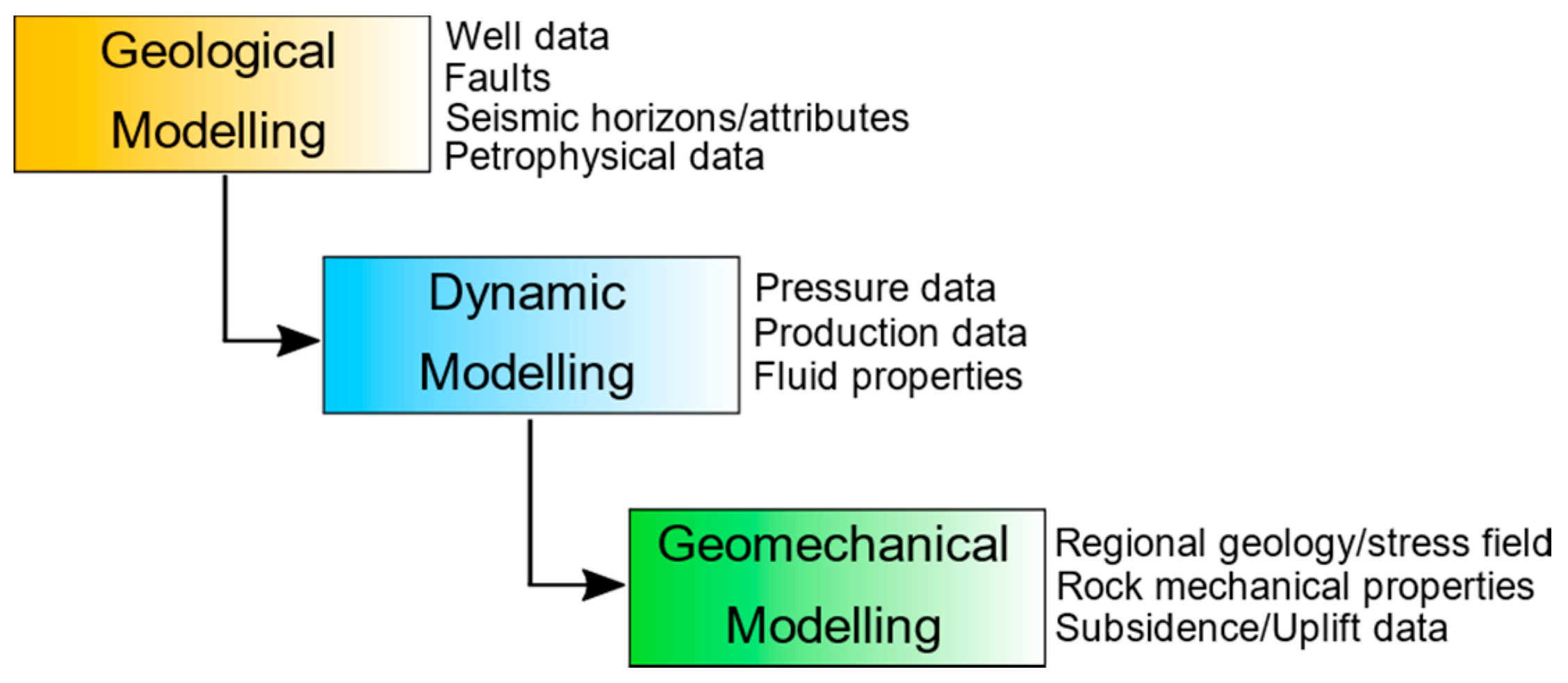
Figure 1. Schematic workflow for a complete reservoir study. Some of the basic input data used at each modeling step are listed on the right part of each box.
Remotesensing 12 03487 g001
Figure 2. 3D view of the regional geological model used for the land displacement analysis during geomechanical simulations, and of the reservoir model used for the flow simulations.
Remotesensing 12 03487 g002
Figure 3. (A) Schematic structural map of the eastern Po Plain showing the geographic area of the underground storage of natural gas (UGS) under study (B). Interpreted seismic section showing the structural–stratigraphic architecture of the buried sequence across the area of interest (modified figure from [30]).
Remotesensing 12 03487 g003
Figure 4. Cross section of the UGS area derived from the 3D seismic volume indicating the main stratigraphic horizons, the geometry of the trap and of the main thrust fault.
Remotesensing 12 03487 g004
Figure 5. Vertical (a) and horizontal (b) velocity maps calculated from Radarsat analysis and the field boundary projection on the surface (white line). The red triangle represents the reference point for Interferometric Synthetic Aperture Radar (InSAR) analysis. Positive values of the vertical and horizontal velocities mean upward and eastward movements, respectively.
Remotesensing 12 03487 g005
Figure 6. Vertical (a) and horizontal (b) displacement amplitude maps calculated from Radarsat analysis and the field boundary projection on the surface (white line). (a) Location of the GNSS station and location of the points used for the displacement time series analysis.
Remotesensing 12 03487 g006
Figure 7. Comparison between the vertical displacement of the internal points from Radarsat (a) and Sentinel (b) analysis and the curve of the field gas cumulative volumes (orange line).
Remotesensing 12 03487 g007
Figure 8. Comparison between the horizontal displacement of the internal points from Radarsat (a) and Sentinel (b) analysis and the curve of the field gas cumulative volumes (orange line).
Remotesensing 12 03487 g008
Figure 9. Time series of the vertical displacement of the external points from Radarsat analysis. The orange line represents the curve of the field gas cumulative volumes.
Remotesensing 12 03487 g009
Figure 10. Time series of the horizontal displacement of the external points from Sentinel analysis. The orange line represents the curve of the field gas cumulative volumes.
Remotesensing 12 03487 g010
Figure 11. TEQC parameters: MP1 and MP2. The increase in the values of MP1 and MP2 for a short period in June 2016 was related to activities on the building where the GNSS is placed.
Remotesensing 12 03487 g011
Figure 12. Coordinates time series along the North, East and vertical component. Positive values mean northward, eastward and upward movements, respectively.
Remotesensing 12 03487 g012
Figure 13. Residuals time series of the GNSS station after removing the linear trend (from Network Approach): light blue line: residual displacement; yellow line: the curve of the field gas cumulative volumes.
Remotesensing 12 03487 g013
Figure 14. Comparison between measured and simulated vertical movements for the internal reference points.
Remotesensing 12 03487 g014
Figure 15. Maps of measured (a) and simulated (b) land surface delta displacement within a historical withdrawal period (March-November). The geographic location of the points P1, P2, P3 is shown in Figure 6.
Remotesensing 12 03487 g015
Table 1. Main feature of the Global Navigation Satellite System (GNSS) data processing approaches. ERP: Earth rotation parameters. IGS: International GNSS Service. CLK: clock correction.
FeatureNetwork ApproachPrecise Point Positioning Approach
SoftwareBernese v. 5.2Bernese v. 5.2
Each process time spanDaily arc (daily RINEX)Daily arc (daily RINEX)
ObservablesDouble DifferenceOne-way
GNSS Ephemerides; ERPFinal IGSFinal IGS
Clock CorrectionNot strictly required (Final IGS CLK)Final IGS CLK (Mandatory)
Tropospheric ModelingNeill Mapping FunctionVienna Mapping Function (VMF)
Terrestrial Reference FrameITRF2014Forced by the Orbits
Reference Stations in the processBUCU, GRAS, GRAZ, MATE, MEDI, NOT1, SOFI, WTZR, ZIMMNo one
Table 2. Mechanical parameters used for characterizing the geomechanical model. E: Young’s Modulus; ν: Poisson’s coefficient; ρ: density; β: Biot’s coefficient; c: cohesion; φ: friction.
FormationsGeomechanical ClassesEνρβcφTensile Cut-Off
[GPa][-][g/cm3][-][105 Pa][°][105 Pa]
Alluvium10.30.392.2014384
Asti sand20.50.392.1014364
Santerno clay35.20.392.181152015
45.00.392.181152015
Santerno clay/P.to Garibaldi sand56.00.392.201123512
66.30.392.181152015
P.to Garibaldi sand78.00.392.181152015
Santerno clay89.50.392.201202420
911.00.392.201202420
1012.90.392.201202420
P.to Corsini sand1115.70.392.401103510
1219.60.392.401203520
1325.30.392.401303530
Basal formation1435.00.392.401503550
Table 3. Main characteristics of the datasets. RSAT1: Radarsat-1; RSAT2: Radarsat-2; S1: Sentinel-1.
SatelliteObservation GeometrySceneTime Interval
RSAT1Ascending right11816/10/2003–09/03/2013
RSAT1Descending right10403/10/2003–20/03/2013
RSAT2Ascending right8721/11/2012–16/10/2019
RSAT2Descending right9225/04/2013–27/10/2019
S1Ascending right22730/03/2015–29/10/2019
S1Descending right23224/10/2014–28/10/2019
Publisher’s Note: MDPI stays neutral with regard to jurisdictional claims in published maps and institutional affiliations.