An Under-Ice Hyperspectral and RGB Imaging System to Capture Fine-Scale Biophysical Properties of Sea Ice


Abstract
1. Introduction
2. Materials and Methods
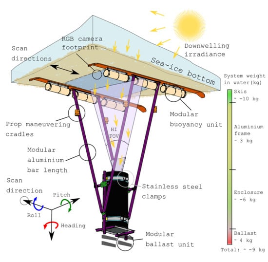
2.1. System Design and Sensors
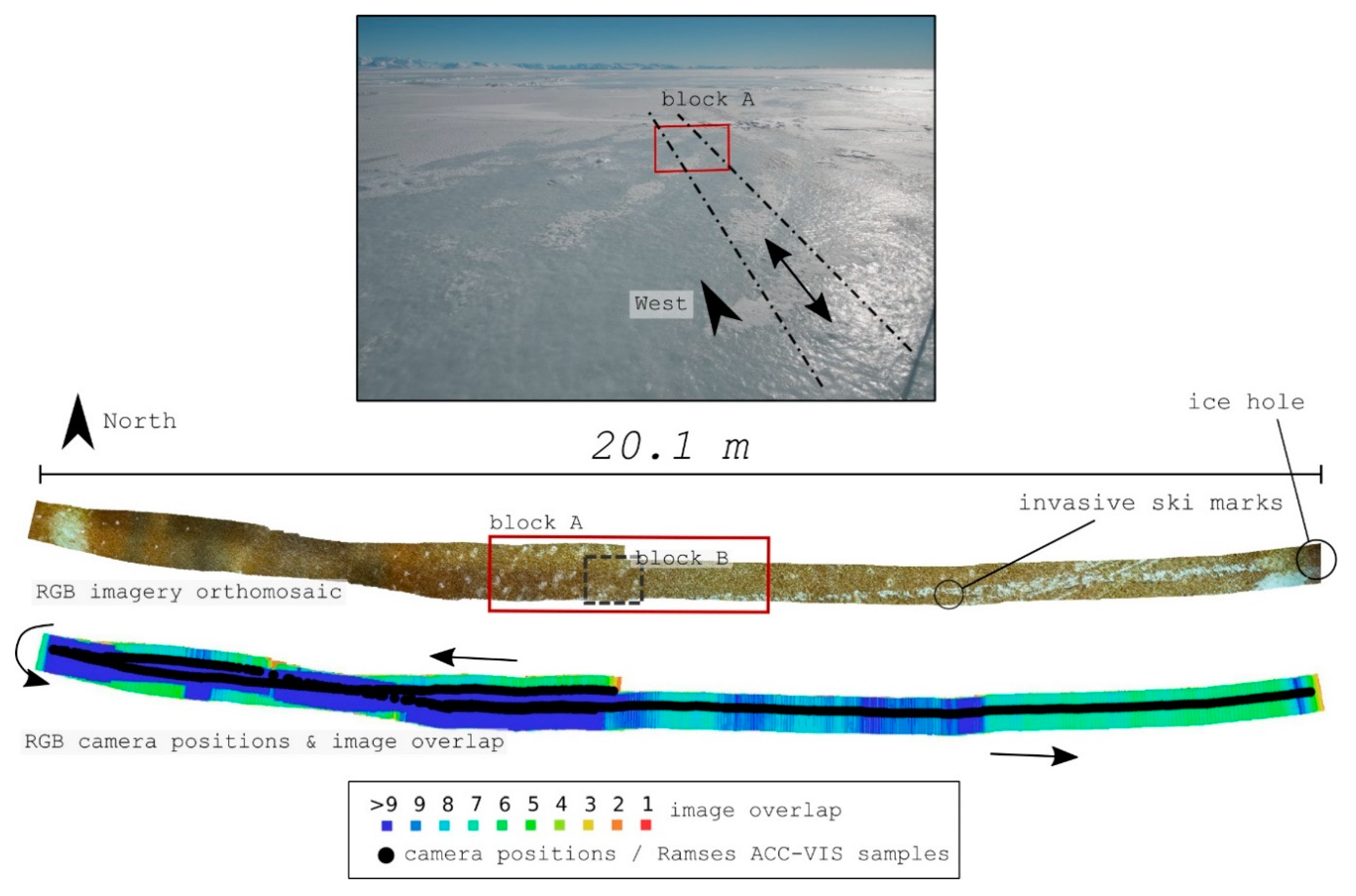
2.2. Field Site and Transect Preparation
2.3. Deployment and Data Acquisition
2.4. Data Processing
2.4.1. RGB Imagery and SfM Digital Photogrammetry
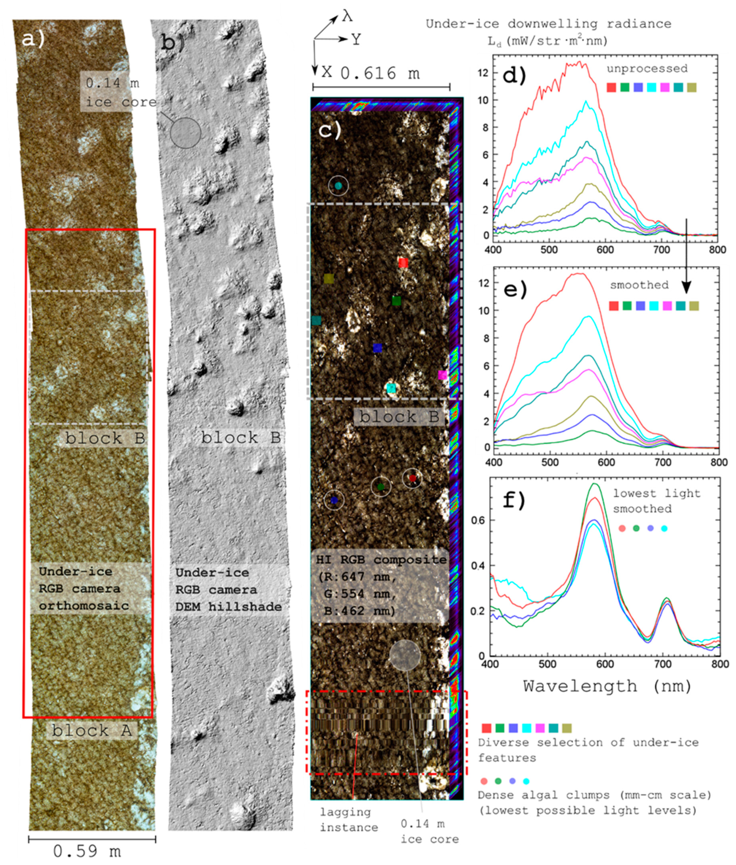
2.4.2. Hyperspectral Imaging and Radiometer Data
3. Results
3.1. Deployment and Operation Performance
3.2. RGB Imagery and Photogrammetry
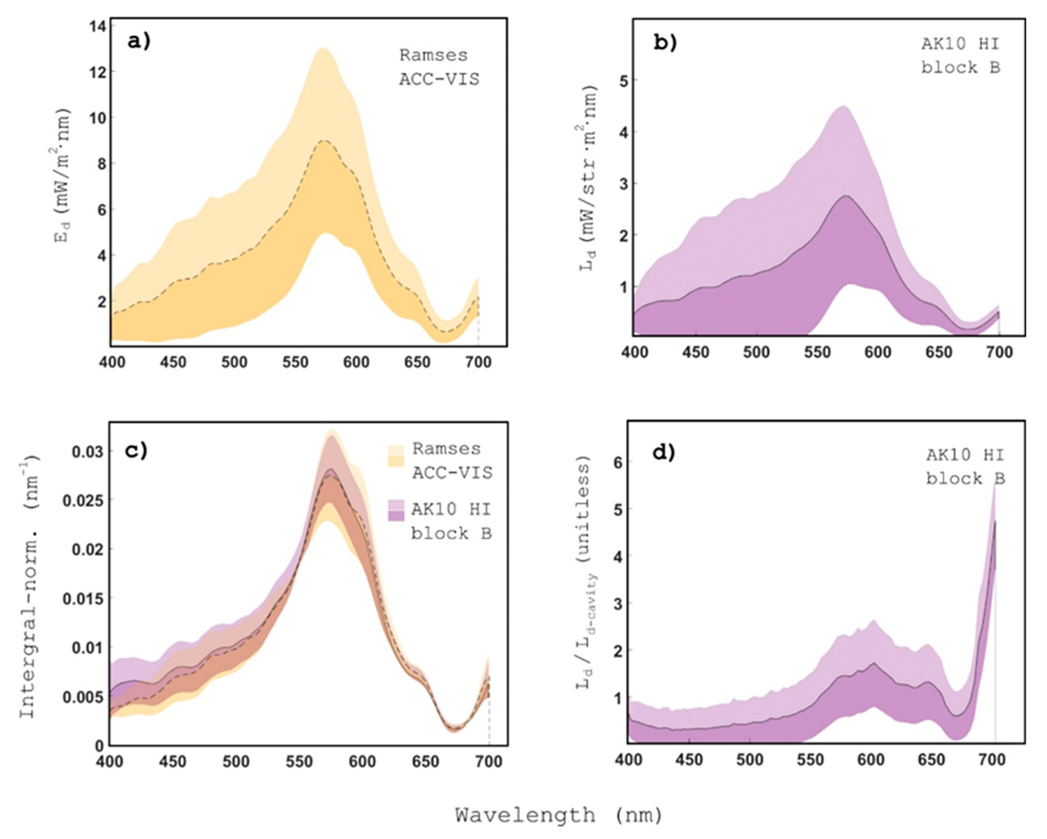
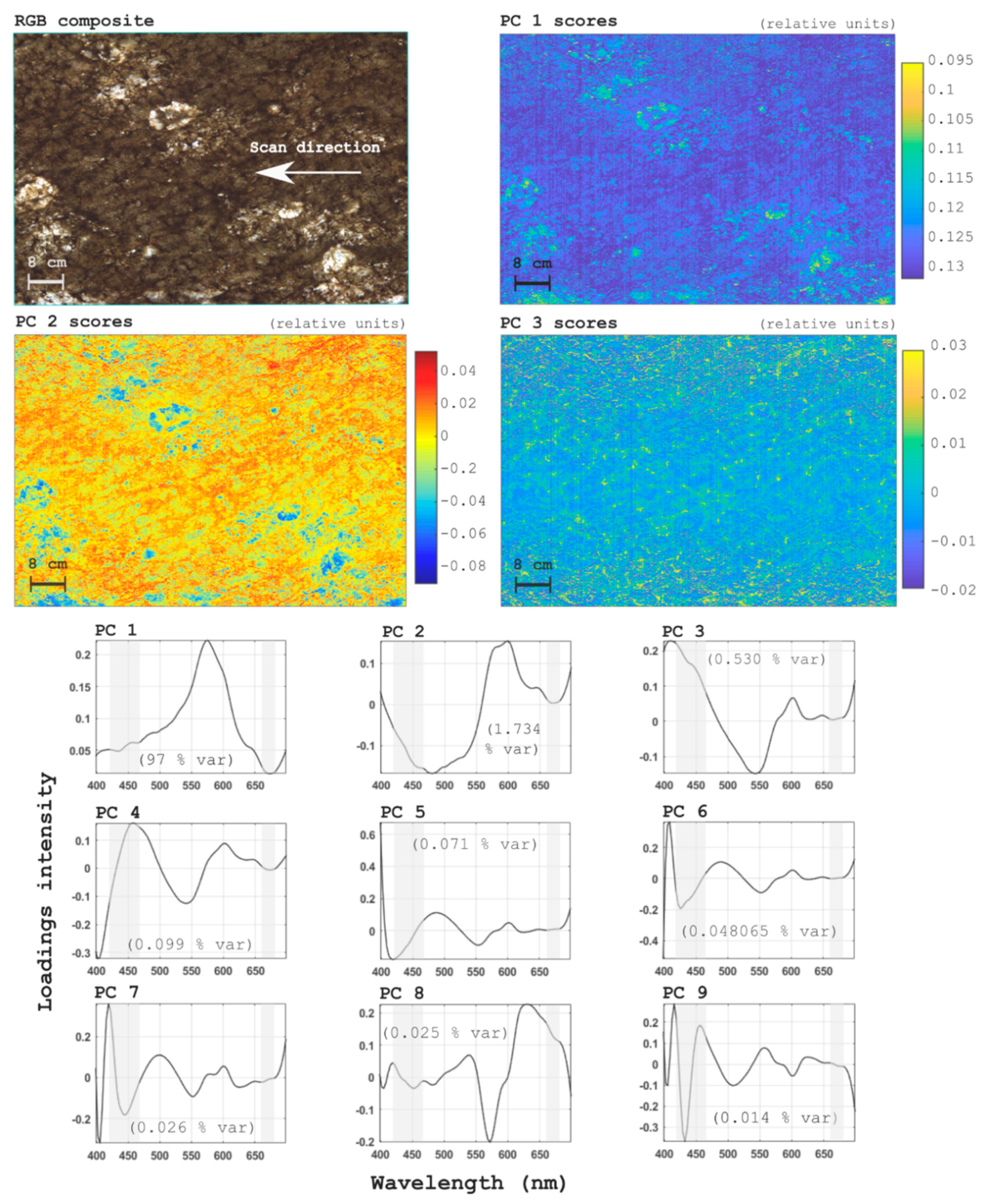
3.3. Hyperspectral Imaging and Radiometric Data
4. Discussion
4.1. Under-Ice Hyperspectral Imaging Data Quality and Processing
4.2. System Performance and Future Developments
4.3. Potential Applications of Under-Ice Hyperspectral and RGB Imaging Payloads
4.4. Caveats and Future Challenges
5. Conclusions and Outlook
Author Contributions
Funding
Acknowledgments
Conflicts of Interest
Appendix A Technical Design and Specifications

References
- Arrigo, K.R. Sea ice as a habitat for primary producers. In Sea Ice; Thomas, D.N., Ed.; John Wiley & Sons, Ltd.: Hoboken, NJ, USA, 2017; pp. 352–369. [Google Scholar]
- Kohlbach, D.; Graeve, M.; Lange, B.A.; David, C.; Schaafsma, F.L.; van Franeker, J.A.; Vortkamp, M.; Brandt, A.; Flores, H. Dependency of Antarctic zooplankton species on ice algae-produced carbon suggests a sea ice-driven pelagic ecosystem during winter. Glob. Chang. Biol. 2018, 24, 4667–4681. [Google Scholar] [CrossRef] [PubMed]
- Van Leeuwe, M.A.; Tedesco, L.; Arrigo, K.R.; Assmy, P.; Campbell, K.; Meiners, K.M.; Rintala, J.M.; Selz, V.; Thomas, D.N.; Stefels, J. Microalgal community structure and primary production in Arctic and Antarctic sea ice: A synthesis. Elem. Sci. Anthr. 2018, 6, 4. [Google Scholar] [CrossRef]
- Cimoli, E.; Meiners, K.M.; Lund-Hansen, L.C.; Lucieer, V. Spatial variability in sea-ice algal biomass: An under-ice remote sensing perspective. Adv. Polar Sci. 2017, 28, 268–296. [Google Scholar]
- Lange, B.A.; Katlein, C.; Nicolaus, M.; Peeken, I.; Flores, H. Sea ice algae chlorophyll a concentrations derived from under-ice spectral radiation profiling platforms. J. Geophys. Res. Ocean. 2016, 121, 8511–8534. [Google Scholar] [CrossRef]
- Miller, L.A.; Fripiat, F.; Else, B.G.; Bowman, J.S.; Brown, K.A.; Collins, R.E.; Ewert, M.; Fransson, A.; Gosselin, M.; Lannuzel, D.; et al. Methods for biogeochemical studies of sea ice: The state of the art, caveats, and recommendations. Elem. Sci. Anthr. 2015, 3, 000038. [Google Scholar] [CrossRef]
- Lange, B.A.; Katlein, C.; Castellani, G.; Fernández-Méndez, M.; Nicolaus, M.; Peeken, I.; Flores, H. Characterizing Spatial Variability of Ice Algal Chlorophyll a and Net Primary Production between Sea Ice Habitats Using Horizontal Profiling Platforms. Front. Mar. Sci. 2017, 4, 349. [Google Scholar] [CrossRef]
- Meiners, K.M.; Arndt, S.; Bestley, S.; Krumpen, T.; Ricker, R.; Milnes, M.; Newbery, K.; Freier, U.; Jarman, S.; King, R.; et al. Antarctic pack ice algal distribution: Floe-scale spatial variability and predictability from physical parameters. Geophys. Res. Lett. 2017, 44, 7382–7390. [Google Scholar] [CrossRef]
- Fernández-Méndez, M.; Olsen, L.M.; Kauko, H.M.; Meyer, A.; Rösel, A.; Merkouriadi, I.; Mundy, C.J.; Ehn, J.K.; Johansson, A.M.; Wagner, P.M.; et al. Algal Hot Spots in a Changing Arctic Ocean: Sea-Ice Ridges and the Snow-Ice Interface. Front. Mar. Sci. 2018, 5, 75. [Google Scholar] [CrossRef]
- Krembs, C.; Tuschling, K.; Juterzenka, K.V. The topography of the ice-water interface – its influence on the colonization of sea ice by algae. Polar Biol. 2002, 25, 106–117. [Google Scholar] [CrossRef]
- Lund-Hansen, L.C.; Hawes, I.; Nielsen, M.H.; Sorrell, B.K. Is colonization of sea ice by diatoms facilitated by increased surface roughness in growing ice crystals? Polar Biol. 2016, 40, 593–602. [Google Scholar] [CrossRef]
- Monti, D.; Legendre, L.; Therriault, J.C.; Demers, S. Horizontal distribution of sea-ice microalgae: Environmental control and spatial processes (southeastern Hudson Bay, Canada). Mar. Ecol. Prog. Ser. 1996, 133, 229–240. [Google Scholar] [CrossRef]
- Ryan, K.G.; Hegseth, E.N.; Martin, A.; Davy, S.K.; O’Toole, R.; Ralph, P.J.; McMinn, A.; Thorn, C.J. Comparison of the microalgal community within fast ice at two sites along the Ross Sea coast, Antarctica. Antarct. Sci. 2006, 18, 583. [Google Scholar] [CrossRef]
- Meiners, K.M.; Vancoppenolle, M.; Carnat, G.; Castellani, G.; Delille, B.; Delille, D.; Dieckmann, G.S.; Flores, H.; Fripiat, F.; Grotti, M.; et al. Chlorophyll- a in Antarctic Landfast Sea Ice: A First Synthesis of Historical Ice Core Data. J. Geophys. Res. Ocean. 2018, 123, 8444–8459. [Google Scholar] [CrossRef]
- Leu, E.; Mundy, C.J.; Assmy, P.; Campbell, K.; Gabrielsen, T.M.; Gosselin, M.; Juul-Pedersen, T.; Gradinger, R. Arctic spring awakening–Steering principles behind the phenology of vernal ice algal blooms. Prog. Oceanogr. 2015, 139, 151–170. [Google Scholar] [CrossRef]
- Meiners, K.M.; Vancoppenolle, M.; Thanassekos, S.; Dieckmann, G.S.; Thomas, D.N.; Tison, J.L.; Arrigo, K.R.; Garrison, D.L.; McMinn, A.; Lannuzel, D.; et al. Chlorophyll a in Antarctic sea ice from historical ice core data. Geophys. Res. Lett. 2012, 39. [Google Scholar] [CrossRef]
- Mundy, C.J.; Ehn, J.K.; Barber, D.G.; Michel, C. Influence of snow cover and algae on the spectral dependence of transmitted irradiance through Arctic landfast first-year sea ice. J. Geophys. Res. 2017, 112. [Google Scholar] [CrossRef]
- Campbell, K.; Mundy, C.J.; Barber, D.G.; Gosselin, M.; Giguère, N. Remote Estimates of Ice Algae Biomass and Their Response to Environmental Conditions during Spring Melt. ARCTIC 2014, 67, 375. [Google Scholar] [CrossRef]
- Melbourne-Thomas, J.; Meiners, K.M.; Mundy, C.J.; Schallenberg, C.; Tattersall, K.L.; Dieckmann, G.S. Algorithms to estimate Antarctic sea ice algal biomass from under-ice irradiance spectra at regional scales. Mar. Ecol. Prog. Ser. 2015, 536, 107–121. [Google Scholar] [CrossRef]
- Lund-Hansen, L.C.; Juul, T.; Eskildsen, T.D.; Hawes, I.; Sorrell, B.; Melvad, C.; Hancke, K. A low-cost remotely operated vehicle (ROV) with an optical positioning system for under-ice measurements and sampling. Cold Reg. Sci. Technol. 2018, 151, 148–155. [Google Scholar] [CrossRef]
- Van Franeker, J.A.; Flores, H.; Van Dorssen, M. The surface and under ice trawl (SUIT). Frozen Desert Alive- Role Sea Ice Pelagic Macrofauna Its Predat. Ph.D. Thesis, University of Groningen, Groningen, The Netherlands, 2009; pp. 181–188. [Google Scholar]
- Forrest, A.L.; Lund-Hansen, L.C.; Sorrell, B.K.; Bowden-Floyd, I.; Lucieer, V.; Cossu, R.; Lange, B.A.; Hawes, I. Exploring Spatial Heterogeneity of Antarctic Sea Ice Algae Using an Autonomous Underwater Vehicle Mounted Irradiance Sensor. Front. Earth Sci. 2019, 7, 1–13. [Google Scholar] [CrossRef]
- Lucieer, V.; Nau, A.; Forrest, A.; Hawes, I. Fine-Scale Sea Ice Structure Characterized Using Underwater Acoustic Methods. Remote Sens. 2016, 8, 821. [Google Scholar] [CrossRef]
- Cimoli, E.; Marcer, M.; Vandecrux, B.; Bøggild, C.E.; Williams, G.; Simonsen, S.B. Application of Low-Cost UASs and Digital Photogrammetry for High-Resolution Snow Depth Mapping in the Arctic. Remote Sens. 2017, 9, 1144. [Google Scholar] [CrossRef]
- Irvine-Fynn, T.D.L.; Sanz-Ablanedo, E.; Rutter, N.; Smith, M.W.; Chandler, J.H. Measuring glacier surface roughness using plot-scale, close-range digital photogrammetry. J. Glaciol. 2014, 60, 957–969. [Google Scholar] [CrossRef]
- Li, T.; Zhang, B.; Cheng, X.; Westoby, M.J.; Li, Z.; Ma, C.; Hui, F.; Shokr, M.; Liu, Y.; Chen, Z.; et al. Resolving Fine-Scale Surface Features on Polar Sea Ice: A First Assessment of UAS Photogrammetry Without Ground Control. Remote Sens. 2019, 11, 784. [Google Scholar] [CrossRef]
- Cimoli, E.; Lucieer, A.; Meiners, K.M.; Lund-Hansen, L.C.; Kennedy, F.; Martin, A.; McMINN, A.; Lucieer, V. Towards improved estimates of sea-ice algal biomass: Experimental assessment of hyperspectral imaging cameras for under-ice studies. Ann. Glaciol. 2017, 58, 68–77. [Google Scholar] [CrossRef]
- Aasen, H.; Honkavaara, E.; Lucieer, A.; Zarco-Tejada, P.J. Quantitative Remote Sensing at Ultra-High Resolution with UAV Spectroscopy: A Review of Sensor Technology, Measurement Procedures, and Data Correction Workflows. Remote Sens. 2018, 10, 1091. [Google Scholar] [CrossRef]
- Adão, T.; Hruška, J.; Pádua, L.; Bessa, J.; Peres, E.; Morais, R.; Sousa, J. Hyperspectral Imaging: A Review on UAV-Based Sensors, Data Processing and Applications for Agriculture and Forestry. Remote Sens. 2017, 9, 1110. [Google Scholar] [CrossRef]
- Jaud, M.; Le Dantec, N.; Ammann, J.; Grandjean, P.; Constantin, D.; Akhtman, Y.; Barbieux, K.; Allemand, P.; Delacourt, C.; Merminod, B. Direct Georeferencing of a Pushbroom, Lightweight Hyperspectral System for Mini-UAV Applications. Remote Sens. 2018, 10, 204. [Google Scholar] [CrossRef]
- Lucieer, A.; Malenovský, Z.; Veness, T.; Wallace, L. HyperUAS-Imaging Spectroscopy from a Multirotor Unmanned Aircraft System. J. Field Robot. 2014, 31, 571–590. [Google Scholar] [CrossRef]
- Chennu, A.; Färber, P.; De’ath, G.; de Beer, D.; Fabricius, K.E. A diver-operated hyperspectral imaging and topographic surveying system for automated mapping of benthic habitats. Sci. Rep. 2017, 7, 7122. [Google Scholar] [CrossRef]
- Mogstad, A.A.; Johnsen, G.; Ludvigsen, M. Shallow-Water Habitat Mapping using Underwater Hyperspectral Imaging from an Unmanned Surface Vehicle: A Pilot Study. Remote Sens. 2019, 11, 685. [Google Scholar] [CrossRef]
- Chennu, A.; Färber, P.; Volkenborn, N.; Al-Najjar, M.A.; Janssen, F.; de Beer, D.; Polerecky, L. Hyperspectral imaging of the microscale distribution and dynamics of microphytobenthos in intertidal sediments: Hyperspectral imaging of MPB biofilms. Limnol. Oceanogr. Methods 2013, 11, 511–528. [Google Scholar] [CrossRef]
- Dumke, I.; Purser, A.; Marcon, Y.; Nornes, S.M.; Johnsen, G.; Ludvigsen, M.; Søreide, F. Underwater hyperspectral imaging as an in situ taxonomic tool for deep-sea megafauna. Sci. Rep. 2018, 8, 12860. [Google Scholar] [CrossRef] [PubMed]
- Dumke, I.; Nornes, S.M.; Purser, A.; Marcon, Y.; Ludvigsen, M.; Ellefmo, S.L.; Johnsen, G.; Søreide, F. First hyperspectral imaging survey of the deep seafloor: High-resolution mapping of manganese nodules. Remote Sens. Environ. 2018, 209, 19–30. [Google Scholar] [CrossRef]
- Yeh, C.-K.; Tsai, V.J.D. Direct georeferencing of airborne pushbroom images. J. Chin. Inst. Eng. 2015, 38, 653–664. [Google Scholar] [CrossRef]
- Friedman, A.; Pizarro, O.; Williams, S.B.; Johnson-Roberson, M. Multi-Scale Measures of Rugosity, Slope and Aspect from Benthic Stereo Image Reconstructions. PLoS ONE 2012, 7, e50440. [Google Scholar] [CrossRef]
- Maas, H.-G. On the Accuracy Potential in Underwater/Multimedia Photogrammetry. Sensors 2015, 15, 18140–18152. [Google Scholar] [CrossRef]
- McCarthy, J.; Benjamin, J. Multi-image Photogrammetry for Underwater Archaeological Site Recording: An Accessible, Diver-Based Approach. J. Marit. Archaeol. 2014, 9, 95–114. [Google Scholar] [CrossRef]
- Raoult, V.; David, P.A.; Dupont, S.F.; Mathewson, C.P.; O’Neill, S.J.; Powell, N.N.; Williamson, J.E. GoProsTM as an underwater photogrammetry tool for citizen science. PeerJ 2016, 4. [Google Scholar] [CrossRef]
- Johnsen, G.; Norli, M.; Moline, M.; Robbins, I.; von Quillfeldt, C.; Sørensen, K.; Cottier, F.; Berge, J. The advective origin of an under-ice spring bloom in the Arctic Ocean using multiple observational platforms. Polar Biol. 2018, 41, 1197–1216. [Google Scholar] [CrossRef]
- Arrigo, K.R.; Brown, Z.W.; Mills, M.M. Sea ice algal biomass and physiology in the Amundsen Sea, Antarctica. Elem. Sci. Anthr. 2014, 2, 000028. [Google Scholar] [CrossRef]
- Johnsen, G.; Volent, Z.; Dierssen, H.; Pettersen, R.; Van Ardelan, M.; Søreide, F.; Fearns, P.; Ludvigsen, M.; Moline, M. Underwater hyperspectral imagery to create biogeochemical maps of seafloor properties. In Subsea Optics and Imaging; Elsevier: Amsterdam, The Netherlands, 2013; pp. 508e–540e. [Google Scholar]
- Huang, H.; Liu, L.; Ngadi, M. Recent Developments in Hyperspectral Imaging for Assessment of Food Quality and Safety. Sensors 2014, 14, 7248–7276. [Google Scholar] [CrossRef] [PubMed]
- Ramirez-Paredes, J.-P.; Lary, D.J.; Gans, N.R. Low-altitude Terrestrial Spectroscopy from a Pushbroom Sensor. J. Field Robot. 2016, 33, 837–852. [Google Scholar] [CrossRef]
- Lund-Hansen, L.C.; Hawes, I.; Sorrell, B.K.; Nielsen, M.H. Removal of snow cover inhibits spring growth of Arctic ice algae through physiological and behavioral effects. Polar Biol. 2014, 37, 471–481. [Google Scholar] [CrossRef]
- Wongpan, P.; Meiners, K.M.; Langhorne, P.J.; Heil, P.; Smith, I.J.; Leonard, G.H.; Massom, R.A.; Clementson, L.A.; Haskell, T.G. Estimation of Antarctic Land-Fast Sea Ice Algal Biomass and Snow Thickness from Under-Ice Radiance Spectra in Two Contrasting Areas. J. Geophys. Res. Ocean. 2018, 123, 1907–1923. [Google Scholar] [CrossRef]
- Morel, A.; Maritorena, S. Bio-optical properties of oceanic waters- A reappraisal. J. Geophys. Res. 2001, 106, 7163–7180. [Google Scholar] [CrossRef]
- Bryson, M.; Johnson-Roberson, M.; Pizarro, O.; Williams, S.B. Colour-Consistent Structure-from-Motion Models using Underwater Imagery. In Robotics: Science and Systems; MIT Press: Cambridge, MA, USA, 2012; pp. 1–8. [Google Scholar]
- Menna, F.; Nocerino, E.; Fassi, F.; Remondino, F. Geometric and Optic Characterization of a Hemispherical Dome Port for Underwater Photogrammetry. Sensors 2016, 16, 48. [Google Scholar] [CrossRef]
- Telem, G.; Filin, S. Photogrammetric modeling of underwater environments. ISPRS J. Photogramm. Remote Sens. 2010, 65, 433–444. [Google Scholar] [CrossRef]
- Łuczyński, T.; Pfingsthorn, M.; Birk, A. The Pinax-model for accurate and efficient refraction correction of underwater cameras in flat-pane housings. Ocean Eng. 2017, 133, 9–22. [Google Scholar] [CrossRef]
- Treibitz, T.; Schechner, Y.; Kunz, C.; Singh, H. Flat Refractive Geometry. IEEE Trans. Pattern Anal. Mach. Intell. 2012, 34, 51–65. [Google Scholar] [CrossRef]
- Shortis, M. Calibration Techniques for Accurate Measurements by Underwater Camera Systems. Sensors 2015, 15, 30810–30826. [Google Scholar] [CrossRef] [PubMed]
- Oniga, V.-E.; Pfeifer, N.; Loghin, A.-M. 3D Calibration Test-Field for Digital Cameras Mounted on Unmanned Aerial Systems (UAS). Remote Sens. 2018, 10, 2017. [Google Scholar] [CrossRef]
- Piazza, P.; Cummings, V.J.; Lohrer, D.M.; Marini, S.; Marriott, P.; Menna, F.; Nocerino, E.; Peirano, A.; Schiaparelli, S. Divers-operated underwater photogrammetry: Applications in the study of antarctic benthos. Int. Arch. Photogramm. Remote Sens. Spat. Inf. Sci. 2018, 42, 885–892. [Google Scholar] [CrossRef]
- Menna, F.; Nocerino, E.; Remondino, F. Flat versus hemispherical dome ports in underwaterphotogrammetry. Int. Arch. Photogramm. Remote Sens. Spat. Inf. Sci. 2017, 42, 481–487. [Google Scholar] [CrossRef]
- Agisoft Metashape User Manual - Professional Edition, Version 1.5. Available online: www.agisoft.com/pdf/metashape-pro_1_5_en.pdf (accessed on 2 December 2019).
- Fonstad, M.A.; Dietrich, J.T.; Courville, B.C.; Jensen, J.L.; Carbonneau, P.E. Topographic structure from motion: A new development in photogrammetric measurement. Earth Surf. Process. Landf. 2013, 38, 421–430. [Google Scholar] [CrossRef]
- Tonkin, T.N.; Midgley, N.G. Ground-Control Networks for Image Based Surface Reconstruction: An Investigation of Optimum Survey Designs Using UAV Derived Imagery and Structure-from-Motion Photogrammetry. Remote Sens. 2016, 8, 786. [Google Scholar] [CrossRef]
- Westoby, M.J.; Brasington, J.; Glasser, N.F.; Hambrey, M.J.; Reynolds, J.M. “Structure-from-Motion” photogrammetry: A low-cost, effective tool for geoscience applications. Geomorphology 2012, 179, 300–314. [Google Scholar] [CrossRef]
- Savitzky, A.; Golay, M.J. Smoothing and Differentiation of Data by Simplified Least Squares Procedures. Anal. Chem. 1964, 36, 1627–1639. [Google Scholar] [CrossRef]
- Schafer, R.W. What Is a Savitzky-Golay Filter? [Lecture Notes]. IEEE Signal Process. Mag. 2011, 28, 111–117. [Google Scholar] [CrossRef]
- Craig, S.E.; Jones, C.T.; Li, W.K.; Lazin, G.; Horne, E.; Caverhill, C.; Cullen, J.J. Deriving optical metrics of coastal phytoplankton biomass from ocean colour. Remote Sens. Environ. 2012, 119, 72–83. [Google Scholar] [CrossRef]
- Lubac, B.; Loisel, H. Variability and classification of remote sensing reflectance spectra in the eastern English Channel and southern North Sea. Remote Sens. Environ. 2007, 110, 45–58. [Google Scholar] [CrossRef]
- Amigo, J.M.; Babamoradi, H.; Elcoroaristizabal, S. Hyperspectral image analysis. A tutorial. Anal. Chim. Acta 2015, 896, 34–51. [Google Scholar] [CrossRef] [PubMed]
- Nicolaus, M.; Petrich, C.; Hudson, S.R.; Granskog, M.A. Variability of light transmission through Arctic land-fast sea ice during spring. Cryosphere 2013, 7, 977–986. [Google Scholar] [CrossRef]
- Malenovsky, Z.; Ufer, C.; Lhotáková, Z.; Clevers, J.G.; Schaepman, M.E.; Albrechtová, J.; Cudlín, P. A new hyperspectral index for chlorophyll estimation: Area under curve normalised to maximal band depth between 650-725 nm. EARSeL eProc. 2006, 5, 12. [Google Scholar]
- Malenovský, Z.; Lucieer, A.; King, D.H.; Turnbull, J.D.; Robinson, S.A. Unmanned aircraft system advances health mapping of fragile polar vegetation. Methods Ecol. Evol. 2017, 8, 1842–1857. [Google Scholar] [CrossRef]
- Kokaly, R.F.; Clark, R.N. Spectroscopic determination of leaf biochemistry using band-depth analysis of absorption features and stepwise multiple linear regression. Remote Sens. Environ. 1999, 67, 21. [Google Scholar] [CrossRef]
- Petrich, C.; Eicken, H. Overview of sea ice growth and properties. In Sea Ice; Thomas, D.N., Ed.; John Wiley & Sons, Ltd.: Chichester, UK, 2016; pp. 1–41. [Google Scholar]
- Polashenski, C.; Perovich, D.; Courville, Z. The mechanisms of sea ice melt pond formation and evolution: Mechanisms of melt pond evolution. J. Geophys. Res. Oceans 2012, 117. [Google Scholar] [CrossRef]
- Weeks, W.F.; Gow, A.J. Preferred Crystal Orientations in the Fast Ice Along the Margins of the Arctic Ocean. J. Geophys. Res. 1978, 83, 5105–5121. [Google Scholar] [CrossRef]
- Legendre, L.; Gosselin, M. In situ spectroradiometric estimation of microalgal biomass in first-year sea ice. Polar Biol. 1991, 11, 113–115. [Google Scholar] [CrossRef]
- Foglini, F.; Grande, V.; Marchese, F.; Bracchi, V.A.; Prampolini, M.; Angeletti, L.; Castellan, G.; Chimienti, G.; Hansen, I.M.; Gudmundsen, M.; et al. Application of Hyperspectral Imaging to Underwater Habitat Mapping, Southern Adriatic Sea. Sensors 2019, 19, 2261. [Google Scholar] [CrossRef]
- Kirk, J.T.O. Light and Photosynthesis in Aquatic Ecosystems, 3rd ed.; Cambridge University Press: Cambridge, UK; New York, NY, USA, 2011. [Google Scholar]
- Lund-Hansen, L.C.; Markager, S.; Hancke, K.; Stratmann, T.; Rysgaard, S.; Ramløv, H.; Sorrell, B.K. Effects of sea-ice light attenuation and CDOM absorption in the water below the Eurasian sector of central Arctic Ocean (>88°N). Polar Res. 2015, 34, 23978. [Google Scholar] [CrossRef]
- Malenovský, Z.; Homolová, L.; Zurita-Milla, R.; Lukeš, P.; Kaplan, V.; Hanuš, J.; Gastellu-Etchegorry, J.P.; Schaepman, M.E. Retrieval of spruce leaf chlorophyll content from airborne image data using continuum removal and radiative transfer. Remote Sens. Environ. 2013, 131, 85–102. [Google Scholar] [CrossRef]
- Arroyo-Mora, J.P.; Kalacska, M.; Inamdar, D.; Soffer, R.; Lucanus, O.; Gorman, J.; Naprstek, T.; Schaaf, E.S.; Ifimov, G.; Elmer, K.; et al. Implementation of a UAV–Hyperspectral Pushbroom Imager for Ecological Monitoring. Drones 2019, 3, 12. [Google Scholar] [CrossRef]
- Fang, H.; Hu, B.; Yu, Z.; Xu, H.; He, C.; Li, A.; Liu, Y. Semi-automatic geometric correction of airborne hyperspectral push-broom images using ground control points and linear features. Int. J. Remote Sens. 2018, 39, 4115–4129. [Google Scholar] [CrossRef]
- Habib, A.; Han, Y.; Xiong, W.; He, F.; Zhang, Z.; Crawford, M. Automated Ortho-Rectification of UAV-Based Hyperspectral Data over an Agricultural Field Using Frame RGB Imagery. Remote Sens. 2016, 8, 796. [Google Scholar] [CrossRef]
- Turner, D.; Lucieer, A.; Malenovský, Z.; King, D.; Robinson, S. Spatial Co-Registration of Ultra-High Resolution Visible, Multispectral and Thermal Images Acquired with a Micro-UAV over Antarctic Moss Beds. Remote Sens. 2014, 6, 4003–4024. [Google Scholar] [CrossRef]
- Marcer, M.; Stentoft, P.A.; Bjerre, E.; Cimoli, E.; Bjørk, A.; Stenseng, L.; Machguth, H. Three Decades of Volume Change of a Small Greenlandic Glacier Using Ground Penetrating Radar, Structure from Motion, and Aerial Photogrammetry. Arct. Antarct. Alp. Res. 2017, 49, 411–425. [Google Scholar] [CrossRef]
- Nicolaus, M.; Katlein, C. Mapping radiation transfer through sea ice using a remotely operated vehicle (ROV). Cryosphere 2013, 7, 763–777. [Google Scholar] [CrossRef]
- Cazenave, F.; Zook, R.; Carroll, D.; Flagg, M.; Kim, S. Development of the Rov Scini and deployment in Mcmurdo sound, Antarctica. J. Ocean Technol. 2011, 6, 20. [Google Scholar]
- Williams, G.; Maksym, T.; Wilkinson, J.; Kunz, C.; Murphy, C.; Kimball, P.; Singh, H. Thick and deformed Antarctic sea ice mapped with autonomous underwater vehicles. Nat. Geosci. 2014, 8, 61–67. [Google Scholar] [CrossRef]
- Wang, L.; Zhou, X.; Zhu, X.; Dong, Z.; Guo, W. Estimation of biomass in wheat using random forest regression algorithm and remote sensing data. Crop J. 2016, 4, 212–219. [Google Scholar] [CrossRef]
- Blondeau-Patissier, D.; Gower, J.F.R.; Dekker, A.G.; Phinn, S.R.; Brando, V.E. A review of ocean color remote sensing methods and statistical techniques for the detection, mapping and analysis of phytoplankton blooms in coastal and open oceans. Prog. Oceanogr. 2014, 123, 123–144. [Google Scholar] [CrossRef]
- Matus-Hernández, M.Á.; Hernández-Saavedra, N.Y.; Martínez-Rincón, R.O. Predictive performance of regression models to estimate Chlorophyll-a concentration based on Landsat imagery. PLoS ONE 2018, 13, e0205682. [Google Scholar] [CrossRef]
- Malenovský, Z.; Turnbull, J.D.; Lucieer, A.; Robinson, S.A. Antarctic moss stress assessment based on chlorophyll content and leaf density retrieved from imaging spectroscopy data. New Phytol. 2015, 208, 608–624. [Google Scholar] [CrossRef] [PubMed]
- Näsi, R.; Viljanen, N.; Kaivosoja, J.; Alhonoja, K.; Hakala, T.; Markelin, L.; Honkavaara, E. Estimating Biomass and Nitrogen Amount of Barley and Grass Using UAV and Aircraft Based Spectral and Photogrammetric 3D Features. Remote Sens. 2018, 10, 1082. [Google Scholar] [CrossRef]
- Shen, X.; Cao, L.; Yang, B.; Xu, Z.; Wang, G. Estimation of Forest Structural Attributes Using Spectral Indices and Point Clouds from UAS-Based Multispectral and RGB Imageries. Remote Sens. 2019, 11, 800. [Google Scholar] [CrossRef]
- Taghizadeh, M.; Gowen, A.A.; O’Donnell, C.P. Comparison of hyperspectral imaging with conventional RGB imaging for quality evaluation of Agaricus bisporus mushrooms. Biosyst. Eng. 2011, 108, 191–194. [Google Scholar] [CrossRef]
- Ambrose, W.G.; von Quillfeldt, C.; Clough, L.M.; Tilney, P.V.R.; Tucker, T. The sub-ice algal community in the Chukchi sea: Large- and small-scale patterns of abundance based on images from a remotely operated vehicle. Polar Biol. 2005, 28, 784–795. [Google Scholar] [CrossRef]
- Katlein, C.; Fernández-Méndez, M.; Wenzhöfer, F.; Nicolaus, M. Distribution of algal aggregates under summer sea ice in the Central Arctic. Polar Biol. 2015, 38, 719–731. [Google Scholar] [CrossRef]
- Jesus, B.; Mouget, J.-L.; Perkins, R.G. Detection of Diatom Xanthophyll Cycle Using Spectral Reflectance. J. Phycol. 2008, 44, 1349–1359. [Google Scholar] [CrossRef]
- Perkins, R.G.; Williamson, C.J.; Brodie, J.; Barillé, L.; Launeau, P.; Lavaud, J.; Yallop, M.L.; Jesus, B. Microspatial variability in community structure and photophysiology of calcified macroalgal microbiomes revealed by coupling of hyperspectral and high-resolution fluorescence imaging. Sci. Rep. 2016, 6, 22343. [Google Scholar] [CrossRef] [PubMed]
- Mehrubeoglu, M.; Teng, M.; Zimba, P. Resolving Mixed Algal Species in Hyperspectral Images. Sensors 2013, 14, 1–21. [Google Scholar] [CrossRef] [PubMed]
- Xi, H.; Hieronymi, M.; Röttgers, R.; Krasemann, H.; Qiu, Z. Hyperspectral Differentiation of Phytoplankton Taxonomic Groups: A Comparison between Using Remote Sensing Reflectance and Absorption Spectra. Remote Sens. 2015, 7, 14781–14805. [Google Scholar] [CrossRef]
- Blackburn, G.A. Wavelet decomposition of hyperspectral data: A novel approach to quantifying pigment concentrations in vegetation. Int. J. Remote Sens. 2007, 28, 2831–2855. [Google Scholar] [CrossRef]
- Pettersen, R.; Johnsen, G.; Bruheim, P.; Andreassen, T. Development of hyperspectral imaging as a bio-optical taxonomic tool for pigmented marine organisms. Org. Divers. Evol. 2014, 14, 237–246. [Google Scholar] [CrossRef]
- Taylor, B.B.; Taylor, M.H.; Dinter, T.; Bracher, A. Estimation of relative phycoerythrin concentrations from hyperspectral underwater radiance measurements––A statistical approach. J. Geophys. Res. Ocean. 2013, 118, 2948–2960. [Google Scholar] [CrossRef]
- Caras, T.; Karnieli, A. Ground-Level Classification of a Coral Reef Using a Hyperspectral Camera. Remote Sens. 2015, 7, 7521–7544. [Google Scholar] [CrossRef]
- Müller, S.; Vähätalo, A.V.; Uusikivi, J.; Majaneva, M.A.M.; Majaneva, S.; Autio, R.; Rintala, J.M. Primary production calculations for sea ice from bio-optical observations in the Baltic Sea. Elem Sci Anthr. 2016, 4, 000121. [Google Scholar] [CrossRef]
- Méléder, V.; Jesus, B.; Barnett, A.; Barillé, L.; Lavaud, J. Microphytobenthos primary production estimated by hyperspectral reflectance. PLoS ONE 2018, 13, e0197093. [Google Scholar] [CrossRef]
- Campbell, K.; Mundy, C.J.; Barber, D.G.; Gosselin, M. Characterizing the sea ice algae chlorophyll a–snow depth relationship over Arctic spring melt using transmitted irradiance. J. Mar. Syst. 2015, 147, 76–84. [Google Scholar] [CrossRef]
- Dustan, P.; Doherty, O.; Pardede, S. Digital Reef Rugosity Estimates Coral Reef Habitat Complexity. PLoS ONE 2013, 8, e57386. [Google Scholar] [CrossRef] [PubMed]
- Gutt, J. The occurrence of sub-ice algal aggregations off northeast Greenland. Polar Biol. 1995, 15, 247–252. [Google Scholar] [CrossRef]
- Krembs, C.; Mock, T.; Gradinger, R. A mesocosm study of physical-biological interactions in artificial sea ice: Effects of brine channel surface evolution and brine movement on algal biomass. Polar Biol. 2001, 24, 356–364. [Google Scholar] [CrossRef]
- Lange, B.A.; Michel, C.; Beckers, J.F.; Casey, J.A.; Flores, H.; Hatam, I.; Meisterhans, G.; Niemi, A.; Haas, C. Comparing Springtime Ice-Algal Chlorophyll a and Physical Properties of Multi-Year and First-Year Sea Ice from the Lincoln Sea. PLoS ONE 2015, 10, e0122418. [Google Scholar] [CrossRef]
- Hop, H.; Pavlova, O. Distribution and biomass transport of ice amphipods in drifting sea ice around Svalbard. Deep Sea Res. Part II Top. Stud. Oceanogr. 2008, 55, 2292–2307. [Google Scholar] [CrossRef]
- Werner, I. Grazing of Arctic under-ice amphipods on sea-ice algae. Mar. Ecol. Prog. Ser. 1997, 160, 93–99. [Google Scholar] [CrossRef][Green Version]
- Arrigo, K.; Dieckmann, G.; Gosselin, M.; Robinson, D.; Fritsen, C.; Sullivan, C. High resolution study of the platelet ice ecosystem in McMurdo Sound, Antarctica:biomass, nutrient, and production profiles within a dense microalgal bloom. Mar. Ecol. Prog. Ser. 1995, 127, 255–268. [Google Scholar] [CrossRef]
- Sture, Ø.; Ludvigsen, M.; Aas, L.M.S. Autonomous underwater vehicles as a platform for underwater hyperspectral imaging. In Proceedings of the OCEANS 2017-Aberdeen, Aberdeen, UK, 19–22 June 2017; pp. 1–8. [Google Scholar]
- Katlein, C.; Perovich, D.K.; Nicolaus, M. Geometric Effects of an Inhomogeneous Sea Ice Cover on the under Ice Light Field. Front. Earth Sci. 2016, 4, 1–10. [Google Scholar] [CrossRef]
- Katlein, C.; Nicolaus, M.; Petrich, C. The anisotropic scattering coefficient of sea ice. J. Geophys. Res. Ocean. 2014, 119, 842–855. [Google Scholar] [CrossRef]
- Aasen, H.; Bolten, A. Multi-temporal high-resolution imaging spectroscopy with hyperspectral 2D imagers—From theory to application. Remote Sens. Environ. 2018, 205, 374–389. [Google Scholar] [CrossRef]
- Buchhorn, M.; Raynolds, M.K.; Walker, D.A. Influence of BRDF on NDVI and biomass estimations of Alaska Arctic tundra. Environ. Res. Lett. 2016, 11, 125002. [Google Scholar] [CrossRef]
- Zhao, F.; Li, Y.; Dai, X.; Verhoef, W.; Guo, Y.; Shang, H.; Gu, X.; Huang, Y.; Yu, T.; Huang, J. Simulated impact of sensor field of view and distance on field measurements of bidirectional reflectance factors for row crops. Remote Sens. Environ. 2015, 156, 129–142. [Google Scholar] [CrossRef]
- Piazza, P.; Cummings, V.; Guzzi, A.; Hawes, I.; Lohrer, A.; Marini, S.; Marriott, P.; Menna, F.; Nocerino, E.; Peirano, A.; et al. Underwater photogrammetry in Antarctica: Long-term observations in benthic ecosystems and legacy data rescue. Polar Biol. 2019, 42, 1061–1079. [Google Scholar] [CrossRef]
- Arrigo, K.R.; Perovich, D.K.; Pickart, R.S.; Brown, Z.W.; Van Dijken, G.L.; Lowry, K.E.; Mills, M.M.; Palmer, M.A.; Balch, W.M.; Bahr, F.; et al. Massive Phytoplankton Blooms Under Arctic Sea Ice. Science 2012, 336, 1408. [Google Scholar] [CrossRef]
- Åhlén, J.; Sundgren, D.; Bengtsson, E. Application of underwater hyperspectral data for color correction purposes. Pattern Recognit. Image Anal. 2007, 17, 170–173. [Google Scholar] [CrossRef]
- Bryson, M.; Johnson-Roberson, M.; Pizarro, O.; Williams, S.B. True Color Correction of Autonomous Underwater Vehicle Imagery. J. Field Robot. 2015, 33, 853–874. [Google Scholar] [CrossRef]
- Yang, C.; Yang, D.; Cao, W.; Zhao, J.; Wang, G.; Sun, Z.; Xu, Z.; Ravi Kumar, M.S. Analysis of seagrass reflectivity by using a water column correction algorithm. Int. J. Remote Sens. 2010, 31, 4595–4608. [Google Scholar] [CrossRef]


| Sensor | Fore-Optics/Lens | Field of View (FOVh/FOVv) | Number of Spatial Pixels | Spectral Range | Spectral Resolution and FWHM |
|---|---|---|---|---|---|
| Specim AISA Kestrel 10 pushbroom sensor | aperture: F/2.4 | 40°/0.0388° in air | 2048 × 1 or 1024 × 1 (binned) | 400–1000 nm | 1.75 / 3.5 / 7 nm/pixel (depending on binning) |
| focal length: 35.375 | ∼29.88°/0.029° underwater | ||||
| Sony a6300 with Samyang AF 35 mm FE | max aperture F/2.8 | 37.2°/25.12° in air | 6000 × 4000 | Visible | RGB |
| focal length: 35 mm | ∼27.5°/18.7° underwater | ||||
| Low Light USB HD cam | focal length: 2.97 mm | 80°/64° in air | 1920 × 1080 | Visible | RGB |
| ∼57.3°/46.6° underwater | |||||
| TriOS Ramses ACC | cosine corrected diffuser | Cosine response | Point sampling | 320–950 nm | 3.3 nm/pixel |
| STS-VIS | CC-3-DA cosine corrected diffuser | Cosine response | Point sampling | 350–800 nm | 3.0 nm/pixel (50 µm slit version) |
| Other components | |||||
| Digital Processing Unit (DPU) | Used to interface and operate all internal sensors/cameras with the surface PC using VNC and has custom electronics from Specim (see Appendix A). Specifications are: Windows 7 Pro, Intel Core i5, 64 bit, 8GB RAM, PIXCI EB1 frame grabber, CameraLink converter, 500 GB HyperX SATA SSD. | ||||
| VN-100 IMU | Measures system attitude used for future geo-rectification of HI imagery (see Appendix A). Operated through the DPU via a Python script. Specifications: 0.5° Static Pitch/Roll, 1.0° Dynamic Pitch/Roll, 5°/hr Gyro In-Run Bias (typ.), 800 Hz IMU Data, ±16 g Accelerometer Range, ±2000°/sec Gyroscope Range, no GPS unit is included in this model. | ||||
| Garmin GPS 18x LVC | Used for above surface GPS lock and time-stamp synchronization (see Appendix A). Specifications: 12-channel GPS receiver tracks, up to 12 satellites, one-pulse-per-second logic-level output with a rising edge aligned to within 1 microsecond of UTC. 1 Hz, output data in NMEA 0183 format. | ||||
| Lumen Subsea Lights (LEDs) | Four units attached as external payload. Intensity manipulated from above surface using a custom build-control. Specifications: Max brightness of 1500 lumens dimmable, beam angle of 135 deg in water and color temperature of 6200 Kelvin. | ||||
© 2019 by the authors. Licensee MDPI, Basel, Switzerland. This article is an open access article distributed under the terms and conditions of the Creative Commons Attribution (CC BY) license (http://creativecommons.org/licenses/by/4.0/).
Share and Cite
Cimoli, E.; Meiners, K.M.; Lucieer, A.; Lucieer, V. An Under-Ice Hyperspectral and RGB Imaging System to Capture Fine-Scale Biophysical Properties of Sea Ice. Remote Sens. 2019, 11, 2860. https://doi.org/10.3390/rs11232860
Cimoli E, Meiners KM, Lucieer A, Lucieer V. An Under-Ice Hyperspectral and RGB Imaging System to Capture Fine-Scale Biophysical Properties of Sea Ice. Remote Sensing. 2019; 11(23):2860. https://doi.org/10.3390/rs11232860
Chicago/Turabian StyleCimoli, Emiliano, Klaus M. Meiners, Arko Lucieer, and Vanessa Lucieer. 2019. "An Under-Ice Hyperspectral and RGB Imaging System to Capture Fine-Scale Biophysical Properties of Sea Ice" Remote Sensing 11, no. 23: 2860. https://doi.org/10.3390/rs11232860
APA StyleCimoli, E., Meiners, K. M., Lucieer, A., & Lucieer, V. (2019). An Under-Ice Hyperspectral and RGB Imaging System to Capture Fine-Scale Biophysical Properties of Sea Ice. Remote Sensing, 11(23), 2860. https://doi.org/10.3390/rs11232860