1. Introduction
A significant share of global CO
2e emissions is generated by the operation of the building stock, particularly to ensure thermal comfort conditions [
1]. In the European Union, buildings are responsible for 36% of energy-related greenhouse gas emissions and are associated with 40% of final energy consumption. Climate neutrality of the EU building stock by 2050 is a core objective of EU climate and energy policy. The EU aims to transform its existing building stock into a zero-emission building stock by 2050, as part of the broader goal of climate neutrality for the entire economy [
2].
Energy renovation programs for existing buildings are being implemented worldwide with the aim of reducing the CO2e footprint associated with building operation. Such energy renovation programs are currently implemented in most EU Member States.
Energy renovation works include upgrading the building envelope, heating and ventilation systems, and/or changing energy sources. However, for older buildings, improving the building envelope is the most frequently applied and discussed approach [
3].
In countries with high seismicity, the long-term effectiveness of energy renovation programs is called into question, since a strong earthquake can severely affect existing buildings [
4]. The benefits of efforts to reduce the CO
2e footprint through energy renovation works may be reduced or even canceled, as damage to structural and non-structural components caused by seismic action will generate the need for seismic strengthening and the re-implementation of energy renovation measures. Directive (EU) 2018/844 of the European Parliament and of the Council of 30 May 2018 [
5] emphasizes that long-term renovation strategies must be adapted to account for “risks related to intense seismic activity affecting energy-efficiency renovations and the service life of buildings”. It is thus established that in high-seismicity areas, energy renovation of existing buildings should be accompanied by measures to increase seismic safety, in order to ensure a building lifespan that allows for maximizing the benefits of energy renovation.
In the development of EU and Member State public policies regarding greenhouse gas emission reductions, there is a need for results demonstrating the benefits of integrated interventions on the building stock. The design and dimensioning of energy renovation programs in seismically active countries should explicitly account for seismic risk. This has led to the development of integrated intervention programs, in which energy renovation measures are implemented simultaneously with seismic strengthening interventions. At the European level, scientific research is increasingly focused on developing technical solutions for integrated interventions combining energy renovation and seismic strengthening, as well as assessing the impact of such integrated interventions on the building stock [
4]. In parallel, recent studies investigated modern seismic retrofit technologies and materials for existing reinforced concrete and masonry buildings, focusing on strategies that enhance lateral strength, stiffness, and global ductility [
6,
7,
8,
9,
10].
Romania represents a particular case due to the specificity of the intermediate-depth Vrancea seismic source, which strongly affects more than 60% of the national territory, covering over 120,000 km2. Consequently, a large existing building stock is susceptible to seismic damage in the event of a major earthquake. This situation is practically unique within the European Union, where Member States exposed to seismic action are generally affected by shallow earthquakes over relatively limited areas, with only a small fraction of the national building stock being exposed to a single seismic source.
In Romania, energy renovation programs funded from public sources have introduced conditions regarding the level of structural safety against seismic actions, declaring ineligible those buildings that exhibit a very high susceptibility to damage under seismic actions. However, approximately 4,000,000 buildings in Romania, representing 70% of the total building stock, were constructed before 1980 and show moderate to high susceptibility to damage under strong seismic actions [
11].
Thus, the majority of Romania’s residential building stock requires interventions for both energy renovation and seismic retrofitting. While energy renovation programs are progressing, especially for multi-family buildings in large cities, seismic retrofitting programs are proceeding at a much slower pace. This raises the question of whether a major earthquake could jeopardize the achievement of the decarbonization target for the building stock by 2050, and how national intervention programs for existing buildings can be best calibrated.
In recent years, significant research efforts have focused on improving the energy performance of building, with an important literature addressing retrofit strategies at the individual building level. However, studies considering building stocks or portfolios remain limited, despite their importance for large-scale decarbonization strategies and long-term planning of renovation actions [
12,
13]. At the same time, increasing attention has been given to the integration of seismic strengthening and energy renovation measures, specific in regions exposed to both seismic risk and high energy demand. Integrated retrofit approaches are widely recognized as promising strategies capable of simultaneously improving structural safety, energy performance, and overall sustainability [
14,
15].
Nevertheless, current practices still largely address seismic and energy interventions separately, and existing retrofit programs are often implemented without a clear strategy for combining available techniques or evaluating their combined effectiveness [
16]. Although several methods and tools for integrated assessment have been proposed, they remain fragmented, lack standardization, and are rarely applied at scale [
17].
Furthermore, recent studies emphasize that retrofit interventions should be assessed within a broader life-cycle perspective, accounting not only for operational energy savings but also for construction impacts, end-of-life aspects, resilience, and social effects on occupants [
18,
19].
Despite these advances, there is still a lack of quantitative analyses comparing the CO2e impacts of different intervention strategies, such as energy renovation, proactive seismic retrofitting, and reactive post-earthquake interventions.
The research presented in this article aims to determine the CO2e footprint associated with the implementation of energy renovation works and, separately, seismic retrofitting for a set of generic buildings characteristic of Romania’s built environment, in accordance with commonly applied technical solutions for energy renovation and, separately, seismic strengthening. Given that the issues of energy and seismic vulnerability of the residential building stock are widely recognized, the Romanian government is seeking to promote national programs in which seismic strengthening and energy renovation interventions are carried out in an integrated manner. However, the planning of such programs requires technical decision-making tools to support the choice of integrated renovation. These tools should also consider the CO2e footprint associated with seismic and/or energy retrofits, as well as the impact of earthquakes on the building stock from the perspective of energy performance. The study presented in this paper can contribute to informing such decisions through global assessments of the CO2e footprint associated with strengthening works.
The evaluation of CO
2e emission values is carried out in accordance with EN 15978:2011 [
20] for upfront emissions, the product stage, and construction process stage, A1–A5. The calculated values are compared with the specific emission values associated with the construction of new buildings. Studies conducted by various authors [
21,
22] show that the CO
2e emissions associated with the construction of new residential concrete buildings are approximately 410 kg CO
2e/m
2.
2. Methodology
2.1. Seismic Retrofitting
In general, seismic retrofitting solutions for buildings differ on a case-by-case basis, being implemented in accordance with the site seismicity, structural type, construction material, and the legal status of existing buildings. In Romania, the most common structural typologies of residential buildings are [
23]:
Multi-story buildings with reinforced concrete walls, built between 1960 and 1990 based on standardized designs, consisting of monolithic or prefabricated reinforced concrete walls, reinforced concrete slabs directly supported on the walls, and continuous foundations cast in situ, typically ranging from 4 to 12 above-ground levels with a basement;
Multi-story buildings with reinforced concrete frames, constructed after 1960, composed of monolithic reinforced concrete columns and beams, concrete slabs supported on beams, and isolated monolithic reinforced concrete foundations, with a height range of 3 to 8 levels, with or without a basement;
Confined masonry structures, consisting of masonry walls confined by horizontal and vertical reinforced concrete elements, concrete slabs supported on masonry walls or beams, continuous monolithic reinforced concrete foundations, with one to four above-ground levels, with or without a basement;
Unconfined masonry structures, consisting of masonry walls, concrete or wooden floors directly supported on masonry walls, and continuous concrete or masonry foundations, with one to three above-ground levels, generally without a basement;
Adobe or other local material structures, mainly used in rural areas, typically with one above-ground level.
For the purposes of this research, multi-story buildings with reinforced concrete frames embedded within masonry, up to ten above-ground levels, built between 1920 and 1940 in major urban centers—particularly in the capital, Bucharest—are also included in the category of confined masonry structures. These buildings proved particularly vulnerable to seismic action during the 4 March 1977 earthquake. A similar approach is also included in the Romanian technical regulation for rapid visual assessment of buildings under seismic action [
24].
Considering these structural typologies, typical seismic retrofitting solutions for residential buildings are [
25]:
The design of seismic retrofitting solutions is generally carried out considering the elasto-plastic response of the retrofitted structures and following the rules for hierarchy of strength capacities to favor a controlled ductile response through bending of structural elements. The behavior factors used to determine the design seismic forces range between 2 and 4, depending on the retrofitting solution employed. Medium-strength concrete, such as class C25/30 or C30/37, is typically used, adapted to the site-specific conditions of the retrofitting works.
For this research, two seismic retrofitting scenarios were considered:
Proactive seismic retrofitting, carried out preventively before the occurrence of a major earthquake capable of severely affecting the building structure;
Reactive seismic retrofitting, performed after a major earthquake has strongly damaged the structure of a vulnerable building.
The implications of proactive seismic retrofitting in terms of decision-making for optimal allocation of funds for safeguarding existing buildings have been analyzed by several authors [
26]. The aim of this study was to quantify the specific material consumption—concrete and steel—required for structural rehabilitation in order to determine the specific CO
2e emissions for the two intervention scenarios.
Seismic retrofitting solutions with consideration of the CO
2e footprint have been analyzed by different authors [
27,
28,
29,
30]. In this study, the retrofitting solutions were designed in accordance with the technical regulations for seismic assessment and retrofitting design of buildings in Romania, P 100-3/2019 [
25], and general engineering practice, without consideration of harmonization with potential energy renovation solutions.
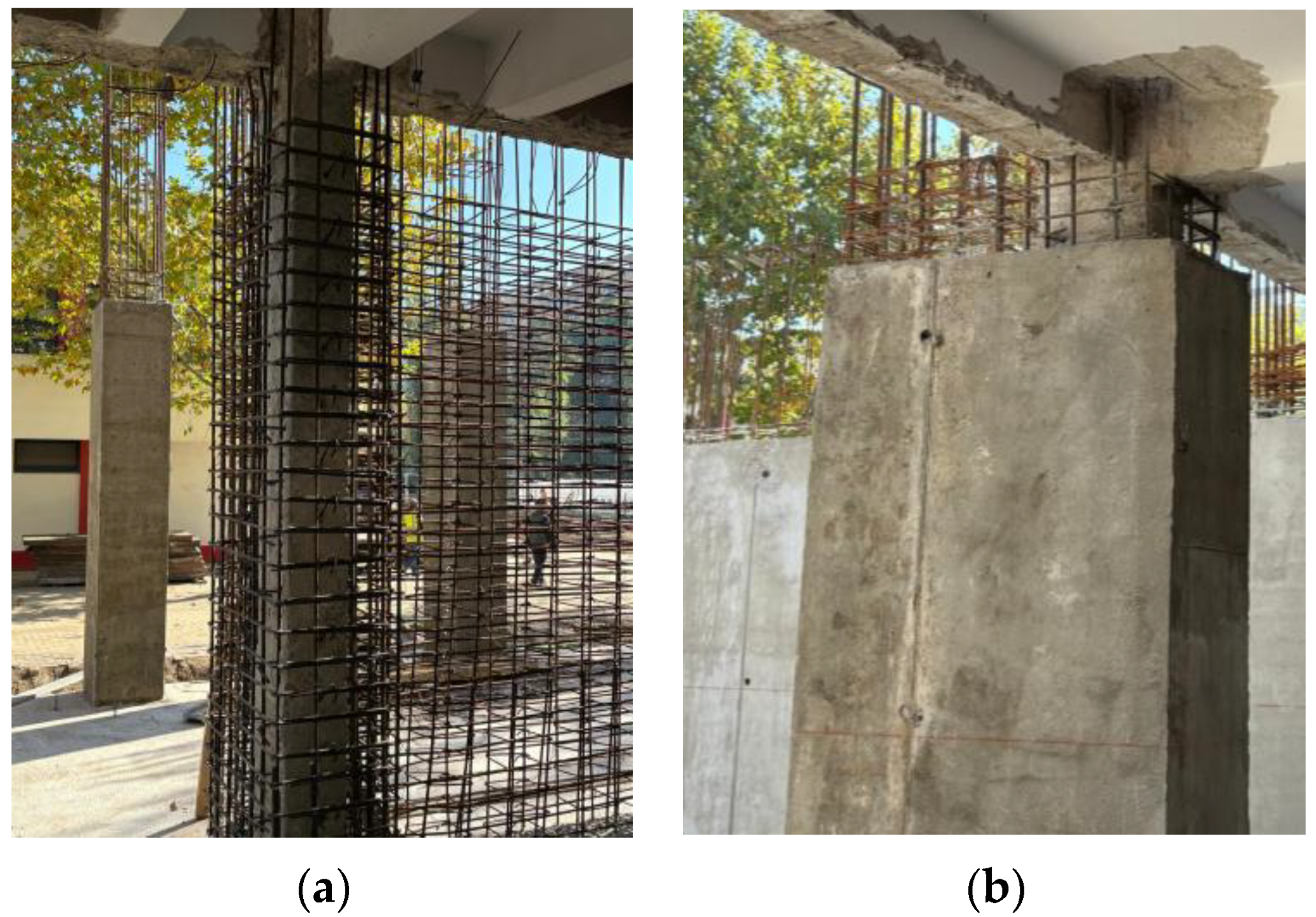
In the case of residential buildings with reinforced concrete or masonry structures, the main retrofitting solution for increasing the seismic capacity in Romania is the introduction of reinforced concrete walls. The existing structures considered in this analysis exhibit high vulnerability to seismic actions when compared to modern requirements for new buildings. For multi-story residential buildings, the following structural characteristics are outlined in this study, in direct relation with the selected retrofitting method:
- -
Large-panel prefabricated concrete buildings exhibit joint deficiencies due to the very small amount of connecting reinforcement and the poor quality of the cast-in-place concrete used in the joints.
- -
Reinforced concrete frame buildings exhibit severe stiffness deficiencies under lateral loads, which can only be compensated for by introducing structural walls that ultimately take over most of the seismic action.
- -
Buildings with monolithic reinforced concrete walls exhibit deficiencies in shear capacity as in many instances the transverse reinforcement is absent starting from the second story.
- -
Confined masonry buildings exhibit very poor material quality and pronounced structural irregularities in plan and elevation.
For these reasons, designers generally choose to strengthen such buildings by introducing a new structural system for lateral loads consisting of reinforced concrete walls. To prevent any kind of structural irregularity, the newly added walls extend from the foundation to the top of the building. It can thus be observed that the study may be considered representative at the building stock level but is less relevant for an individual building considered on its own.
For illustrative design purposes, calculations were performed for a set of four generic building types, with 2, 5, 9, and 11 stories, assuming the following:
Retrofitting is performed by introducing reinforced concrete walls, sized according to the shear resistance requirement.
The specific weight of the buildings is 14 kN/m2 for the two-story buildings and 12 kN/m2 for the others.
The behavior factor used to determine design seismic forces is 2.5 for the two-story buildings and 3.5 for the others.
The adopted values are consistent with the provisions of the national technical regulations for the design of seismic strengthening interventions [
12]. For two-story buildings, a behavior factor of 2.5 is justified by the structural configuration, characterized by relatively high strength and stiffness but limited plastic deformation capacity. Low-rise structures only rarely develop coherent plastic mechanisms that would justify the use of higher behavior factors. When a behavior factor of 2.5 is used in the evaluation of the design seismic forces, and overstrength is accounted for, the structural analysis effectively assumes, in a conservative manner, a quasi-elastic response.
In case of taller structures, a coherent plastic mechanism under the design seismic load can develop and higher redundancy is expected, justifying a higher behavior factor. Newly installed walls are likely to develop plastic hinges at their base.
It is observed that the introduction of new reinforced concrete walls increases lateral stiffness and strength, stabilizes potential story mechanisms, and enables the development of a coherent global plastic mechanism. However, the behavior factor of the strengthened structure does not reach values comparable to those of equivalent newly designed structures.
The concrete class is C25/30 for the two-story buildings and C30/37 for the others.
The overstrength of the structures relative to the seismic design requirement is 2.0 for the two-story buildings and 1.6 for the others.
Flexural overstrength is generated by longitudinal over-reinforcement and by the ratio between the ultimate and yield strength of steel in tension. In the case of long walls, the overstrength due to over-reinforcement can be controlled through appropriate detailing to values in the range of 1.2–1.3. However, the strain hardening effect of steel increases this overstrength to approximately 1.5–1.6. For walls in low-rise buildings, longitudinal reinforcement is often governed by minimal requirements, leading to higher levels of over-reinforcement. Consequently, the flexural overstrength, including the effect of steel strain hardening, typically reaches values around 2.0.
The story height is 4.20 m for the two-story buildings and 2.80 m for the others.
The SDOF–MDOF equivalence factor is 1.0 for the two-story buildings and 0.85 for the others.
This approach is consistent with the recommendation of [
31,
32], considering that the influence of the higher modes in the dynamic response of low-rise structures can be neglected.
The ratio between the lateral resistance of the existing structure and the lateral resistance requirement of an equivalent new structure is 0.45 for the two-story buildings and 0.25 for the others.
This assumption is based on the authors’ experience in assessing existing buildings in Romania constructed before 1981, which are the subject of this research. Although the design rules applied at the time were similar across all building categories, for low-rise buildings the application of minimal detailing criteria naturally results in a relative strength capacity higher than that of taller buildings. The factors presented here consider as well the evolution of seismic design requirements, expressed through the increase in design lateral loads [
33]. The higher fundamental requirements of new seismic design codes, quantified by the increase in design seismic accelerations, has resulted in much of the existing residential building stock no longer meeting current seismic protection standards.
All these values are summarized in
Table 1.
The design seismic forces were calibrated in accordance with the provisions of the Romanian Seismic Design Code, P 100-1/2013 [
31]. Regarding the seismic retrofitting targets, the following general assumptions were considered:
In the design of preventive retrofit, only 75% of the existing structure’s resistance was typically considered, in order to account for uncertainties in material properties, construction quality, degradation, and the reliability of the interaction between existing and newly added structural elements. This reduction provides a safety margin and ensures a conservative assessment of the strengthened system. Therefore, for proactive retrofitting, when determining the lateral resistance capacity of the retrofitted structure, the contribution of the existing structure was multiplied by 0.75, assuming that the existing undamaged structure can contribute significantly to the lateral resistance capacity of the retrofitted system.
In the case of reactive retrofit of damaged structures, only 15% of the original lateral strength was considered as contribution to the lateral strength of the retrofitted structure. This low ratio accounts for the significant uncertainty associated with damage extent, residual capacity, and possible hidden deterioration. This is a conservative approach that reflects the reduced reliability of the existing damaged structural system and ensures that the retrofit design does not decisively rely on compromised structural components. Therefore, for proactive retrofitting, when determining the lateral resistance capacity of the retrofitted structure, the contribution of the existing structure was multiplied by 0.15.
For proactive retrofitting, the target lateral resistance for the entire retrofitted structure is set at 65% of the value prescribed by P 100-1/2013 [
31] for equivalent newly constructed buildings. This assumption takes into account the requirements of P 100-3/2013 [
25] as well as general engineering practice, where it is not feasible to achieve the full parameters of new buildings when intervening on existing vulnerable stock, in order to limit intervention works and make them operational at the level of the existing building stock. A similar reference target of 0.60 is provided for preventive seismic retrofitting by the Italian technical regulation NTC 2018 [
34] for seismic upgrading classified as “miglioramento”. For reactive retrofitting, the lateral resistance of the retrofitted structure is assumed to be 85% of the value prescribed for new buildings; considering that intervention works are extensive and highly disruptive, the existing structure can only marginally be relied upon, and practically a new lateral system must be constructed. A value higher than 0.8 is recommended both in [
31,
34].
Based on these values, the ratio between the contribution to lateral resistance provided by the retrofitted structure and the lateral resistance required by the technical regulation P 100-1/2013 [
31] for new building structures,
, can be determined, as summarized in
Table 2.
In determining the design seismic forces, it was assumed that the fundamental vibration period of the buildings can be approximated as
, where
is the number of stories [
35]. Accordingly, all buildings have periods ranging between 0.1 s and 0.6 s. Considering that the design acceleration spectrum provided by P 100-1/2013 [
31] has control periods
of 1.0 s and 1.6 s for the seismic zones of interest, it was assumed that the amplification factor
is equal to 2.5 for all analyzed buildings.
For estimating the indicative consumption of concrete and steel for seismic retrofitting, the following simplifications were considered:
- -
Total weight of the building, W, is:
where
represents the building’s built-up area.
- -
Seismic design force, , is:
where
represents the design ground acceleration.
- -
The sum of the design shear forces in the concrete shear walls at the ground level, , is:
- -
The total area of the horizontal cross-sections of the newly introduced reinforced concrete walls, , is:
where
is the average allowable shear stress in the wall, equal to 0.67 times the square root of the characteristic compressive strength of the concrete, in accordance with the technical design regulations for reinforced concrete wall structures in Romania [
36].
The volume of the newly introduced reinforced concrete walls is equal to the cross-sectional area multiplied by the building height, i.e., the walls extend uniformly over the entire height of the building.
The percentages of horizontal and transverse reinforcement in the walls, on each face, are 0.35 for the two-story buildings and 0.55 for the multi-story buildings. These values also include concentrated reinforcement positioned at the ends of the cross-sections or at the intersections with slabs. The reinforcement percentages were established in accordance with general engineering practice and [
36].
The CO2e emissions associated with the retrofitting works were calculated based on the quantities of steel and concrete required for seismic retrofitting. For this calculation, it was assumed that in proactive retrofitting, interventions on foundations and adjacent concrete elements represent 20% of the consumption required for constructing the concrete walls. In reactive retrofitting, interventions on foundations and adjacent concrete elements are assumed to represent 60% of the consumption needed for the concrete walls.
For the CO
2e emission calculation, values of 330 kg CO
2e/m
3 of concrete and 5338 kg CO
2e/m
3 of steel were used [
37]. This calculation approach was implemented to allow the estimation of CO
2e emissions for a number of buildings representative in terms of story number, located in seismic zones characterized by different design accelerations. For the purposes of this study, the analyzed buildings are abstract entities, representative of a general typology, without reference to any specific architectural layout.
2.2. Energy Renovation
The methodology used to determine the CO2e footprint of energy renovation differs substantially from that used for seismic retrofitting. This difference arises from the fundamentally different nature of intervention solutions for energy renovation compared to those for seismic retrofitting in Romania.
In Romania, the vast majority of multi-family buildings are owned by multiple individual owners, each owning a single dwelling unit, making Romania the EU country with the highest share of the population living in privately owned housing [
38].
Considering this ownership structure and national commitments regarding the energy renovation of the building stock, intervention solutions were selected to avoid affecting the interior of dwelling units. This allows works to proceed even if not all owners have given their consent, based on the decision of the owners’ association. Energy renovation of existing buildings is mostly carried out through comprehensive interventions on the building envelope, with minor interventions on building services. Consequently, most construction works are performed on the exterior of the building or in common areas. Interventions inside apartments—for example, replacement of heating and domestic hot water systems or installation of mechanical ventilation—would likely halt the renovation programs, as obtaining consent from all owners for interior works is difficult. This particular ownership situation has led to engineering solutions adapted not only to technical realities but also to legal constraints. Interventions are always performed without affecting the functionality of the dwelling units, which can be used at full capacity during the works. This situation contrasts with seismic retrofitting, where interventions necessarily affect the interior of dwelling units and disrupt functionality in the medium term.
Implementing standardized intervention solutions for energy renovation of residential buildings at a national level is also facilitated by the fact that Romania’s urban residential stock was largely developed over a relatively short period (1960–1990) based on standardized designs. Consequently, these buildings have similar energy performance issues and require comparable intervention works.
Interventions for energy renovation of multi-family residential buildings include:
External cladding of building walls with 10 cm thick expanded polystyrene or mineral wool, followed by restoration of the protective and finishing layers;
Replacement of existing wooden double-glass windows with PVC double- or triple-glass thermally insulated windows;
Balcony closure with thermally insulated windows and PVC panels;
Installation of 15–20 cm extruded polystyrene insulation on the roof terrace above the top floor, restoration of the protective layer of the insulation using a mortar or cement-based concrete layer, and refurbishment of the waterproofing using double-layer bituminous membranes;
Thermal insulation of the attic using 10 cm extruded polystyrene and restoration of waterproofing;
Replacement of sills and window ledges with steel sheet;
Insulation of the floor above the basement using 10 cm mineral wool, together with the installation of a protective cement-based mortar layer reinforced with fiberglass mesh and a finishing layer;
Insulation of the walls and ceiling in the stairwell access hall using 10 cm thick expanded polystyrene;
Replacement of entrance doors and windows;
For buildings connected to centralized thermal energy systems, replacement of internal heat supply pipes from the building connection to the vertical risers’ separation points;
Reconstruction of perimeter sidewalks using in situ unreinforced or lightly reinforced concrete.
For this study, specific CO2e emission values were calculated based on the material consumption for energy renovation, determined according to technical design specifications for 11 multi-family buildings.
Material-specific emission values were established following [
37]. Using the bill of quantities from the renovation projects for these 11 buildings, total CO
2e emissions were determined and, by reference to the building’s gross floor area, specific emissions were calculated. These projects were previously used for energy renovation of buildings under national programs.
The calculated values account for the production of construction materials, including raw material extraction (A1), transport of raw materials (A2), and material manufacturing (A3).
The impact of transporting construction materials (A4) was estimated assuming an average transport distance of 150 km using 10 t trucks suitable for dense urban areas, with a truck load factor of 50%.
The impact of on-site installation of construction materials was estimated according to the installation method, considering three categories of work:
Light works performed manually without heavy machinery;
Moderate works requiring light machinery, with associated production and disposal of waste;
Heavy works requiring heavy machinery, lifting equipment, cranes, and generating large quantities of waste.
Depending on the work category, the CO
2e emissions associated with the materials were increased by the percentages indicated in
Table 3.
Considering the specific CO2e emissions of the constituent materials for each system used in energy renovation, the specific CO2e emissions for each system were determined individually. Taking into account their contribution to the total CO2e balance for each project, the following systems were considered in this study, identified from the analysis of the technical projects for the 11 buildings:
EPS cladding (3 cm, 5 cm, 8 cm, 10 cm, 15 cm, or 20 cm thick);
Extruded polystyrene (XPS) cladding (5 cm, 10 cm, or 15 cm thick);
Glass wool (GW) cladding (8 cm, 10 cm, or 12 cm thick);
Galvanized metal sill (60 cm, 40 cm, or 20 cm wide);
Bituminous membrane (1 or 2 layers);
Glazing (double or triple);
Autoclaved aerated concrete (AAC) brick cladding (15 cm, 25 cm, or 40 cm);
PVC sandwich panels (5 cm or 10 cm thick);
Concrete- or cement-based mortar panels (5 cm or 8 cm thick);
Transport with 10 t trucks.
For each system used, the constituent elements were considered according to the technical specifications in the projects. For example, for 10 cm thick expanded polystyrene cladding, the component parts detailed in
Table 4 were considered. For glass wool cladding, the component parts detailed in
Table 5 were considered.
The CO2e emissions for each system used in the energy renovation of a building were determined as the product of the system-specific emission values and the quantities installed for each building. The quantities installed were determined based on the technical design specifications.
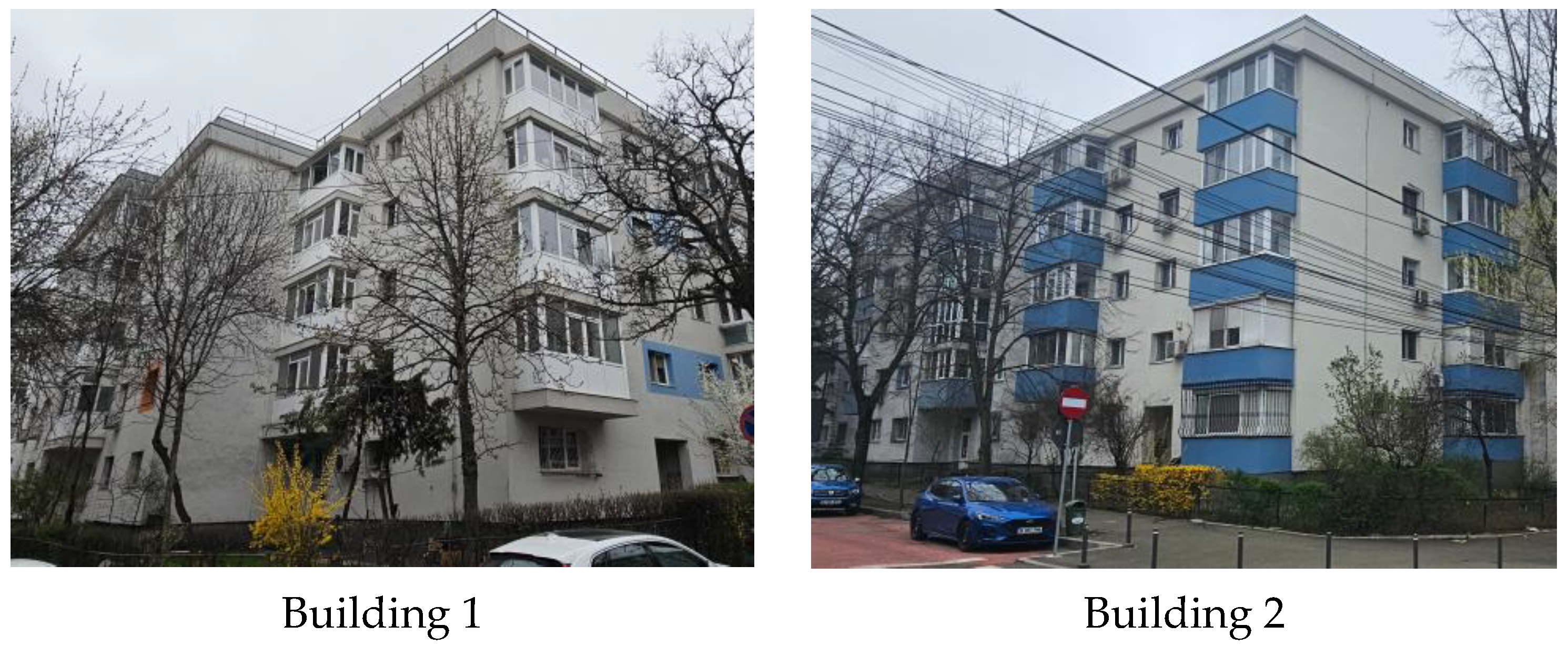
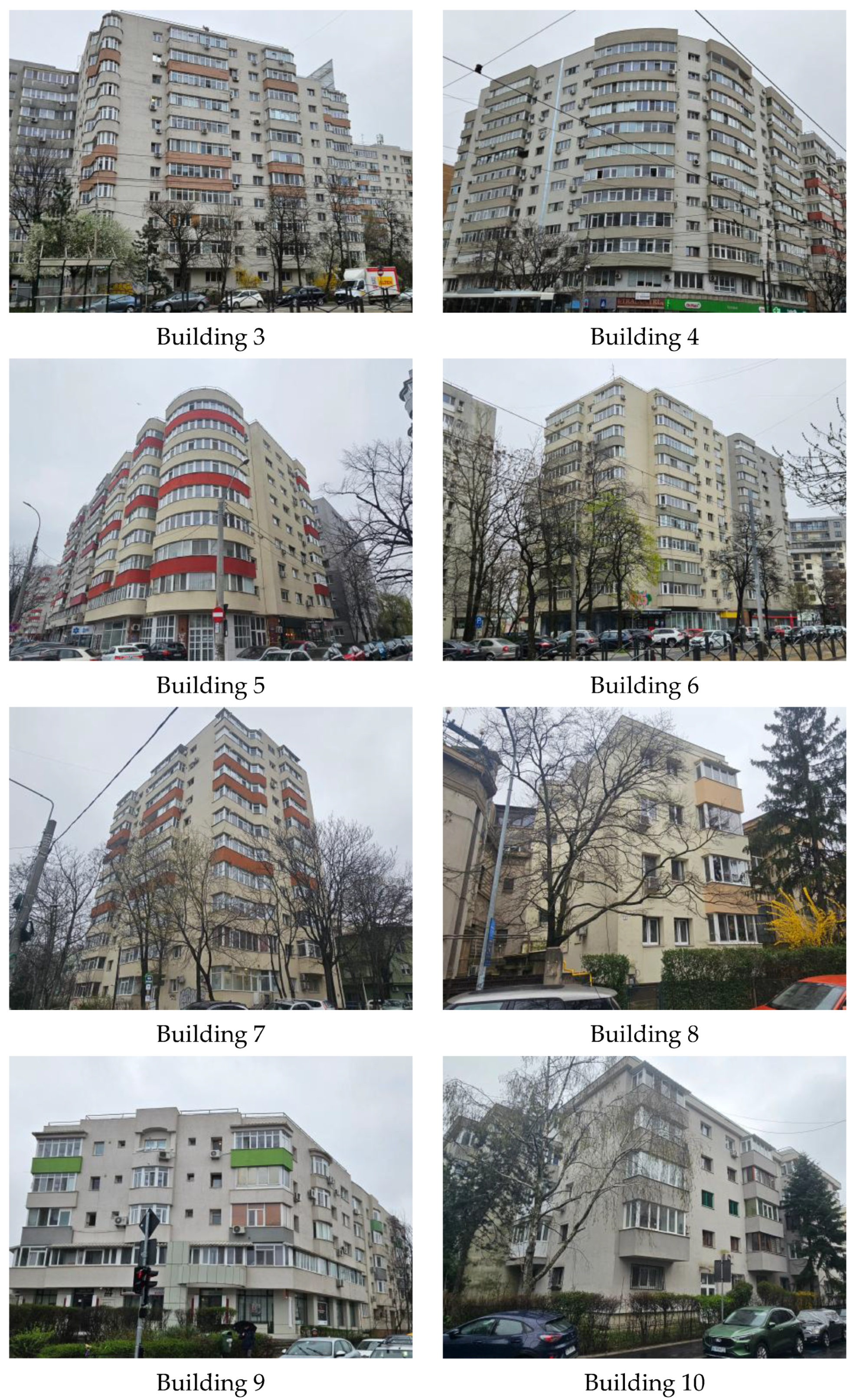
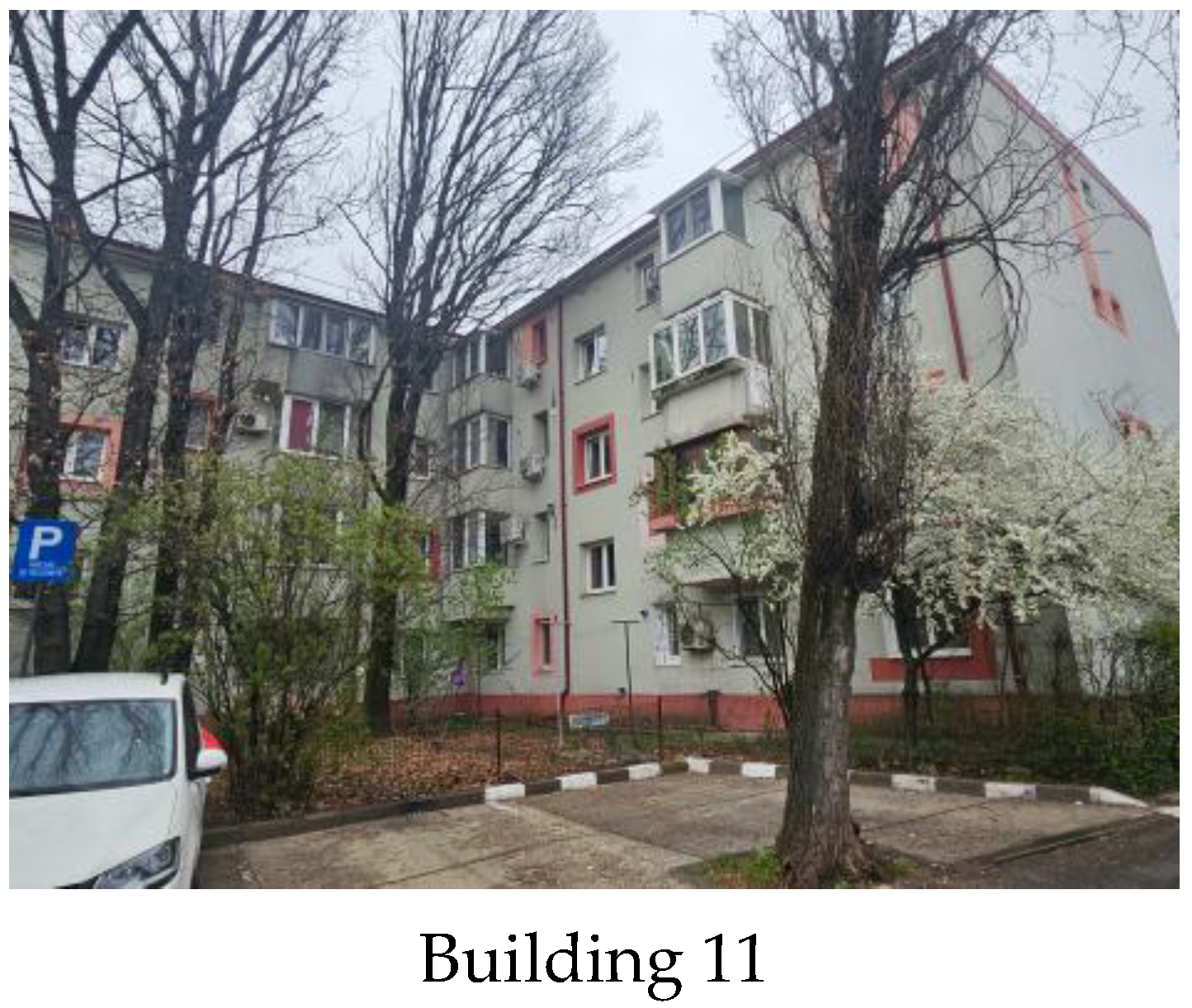
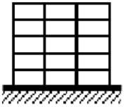
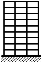
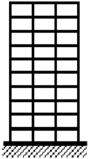
The analyzed buildings are typical residential buildings (
Figure 2), with reinforced concrete structures and envelopes consisting of either prefabricated reinforced concrete walls or masonry walls, wooden double-leaf windows, steel entrance doors with single-glass panes, and a non-trafficable roof terrace insulated with autoclaved aerated concrete. The selection of buildings was carried out so that they would be representative of the multi-family residential building stock. It should be noted that urban development in Romania that took place mainly between 1960 and 1990, during a centralized economic system in which almost all economic entities were publicly owned. Therefore, the residential buildings were constructed based on a limited number of standard design types, typically for 5-story or 9–11-story buildings, implemented nationwide. As a result, the variability of architectural and structural solutions in the residential sector is relatively low. The 11 buildings were selected to be representative of these two height categories, in the sense that their architectural and structural characteristics are found in most residential buildings constructed during that period.
A summary of the analyzed buildings is presented in
Table 6.
The chosen methodology allows the analysis of a relatively large number of buildings, which are not individualized through specific architectural projects, based on the bill of quantities from energy renovation technical specifications. The aim of this study is not to identify specific energy renovation solutions but to estimate the CO2e emissions associated with typical solutions already widely implemented in energy renovation programs. The buildings were selected to be representative of the residential building stock in urban areas and to provide an overview of the expected CO2e emissions from energy renovation of the national building stock.
Although the use of software platforms for life-cycle assessment of buildings could likely provide more accurate estimates of emissions, such platforms do not allow the methodology to be extrapolated to a very large number of buildings and require detailed architectural information, which is beyond the scope of this research.
3. Results
3.1. Seismic Strengthening
For 1000 m
2 of built-up area, considering the design acceleration values provided by P 100-1 for different seismic zones, the required areas of reinforced concrete walls to achieve the seismic retrofitting target were determined using the method described in
Section 2.1.
In the case of proactive retrofitting, the cumulative wall areas, for each calculation direction, range from 0.96 m2 for two-story buildings located in seismic zones with to 7.97 m2 for 11-story buildings in zones with . For reactive retrofitting, the wall area at the ground floor ranges from 2.40 m2 to 13.90 m2.
Considering these determined values and the additional consumption associated with interventions on foundations and existing concrete elements, the resulting specific CO
2e emissions are presented in
Table 7 for proactive retrofitting and
Table 8 for reactive retrofitting.
If, at the national level, a design acceleration value is calculated by weighting the values specified for each locality by the local population, a weighted average design acceleration of 0.27 g is obtained.
Considering that two-story buildings are single-family dwellings and buildings with more than two stories are multi-family dwellings, the specific CO
2e emission values corresponding to this design acceleration are presented in
Table 9 and
Table 10. This building classification is conventionally adopted in this study to allow the use of the results for supporting national intervention programs on the building stock, which treat multi-family and single-family buildings separately.
The values indicated in this paragraph refer only to the materials used for seismic retrofitting, either through the construction of new structural components or the jacketing of existing elements. Interventions on non-structural components, if necessary, are not considered in this study, as they are regarded as serving a purpose separate from seismic retrofitting and fall within the broader concept of functional and architectural rehabilitation.
3.2. Energy Renovation
By applying the methodology described in
Section 2.2, the specific CO
2e emissions for each system used in the energy renovation of buildings were determined. Each system was analyzed according to the design specifications used in this research. The resulting CO
2e emission values are presented in
Table 11. The values indicated in the third column represent specific CO
2e emissions, i.e., emissions normalized to the unit of measure. The unit of measure depends on the nature of the system: for surface applications, square meters were used; for linear applications, linear meters were used.
Although not directly comparable, the specific CO2e emissions for expanded polystyrene cladding are considerably lower than the values calculated for glass wool cladding. This difference is largely due to the significantly thicker mortar layer required to cover the insulation when glass wool is used. Additionally, it is observed that the installation of triple-glass windows is clearly less favorable in terms of CO2e emissions compared to using 10 cm PVC panels. This should be taken into account when insulating balconies, where there is a tendency to replace existing opaque parapets with triple-glass windows instead of using thermally insulated PVC panels.
Based on the specific CO
2e emissions for each system, the total CO
2e emission associated with the energy renovation was determined for each analyzed building.
Table 12 presents an illustrative evaluation of the contribution of each system to the total CO
2e emissions for Building 2.
Analysis of the data presented in
Table 12 shows that the largest share of CO
2e emissions required for renovating the building envelope is caused by window replacement (approximately 47%), 18% are due to waterproofing of the non-trafficable roof terrace, and 9% are associated with the protective mortar layer over the thermal insulation on the terrace. These three categories of work together account for 75% of the total CO
2e emissions for energy renovation of the envelope.
Table 13 shows the percentage contribution of each type of work.
The significant contribution of glazing to the CO2e footprint associated with building envelope rehabilitation is due to the high emission factor of glass compared to the other materials used. Furthermore, envelope rehabilitation typically involves replacing all windows and enclosing all balconies with insulating glazing. Estimates from this study indicate that, for triple-glass windows, approximately 75% of the window’s CO2e footprint is attributable to the glass itself.
The specific CO
2e emission, calculated as the total CO
2e emission in kilograms divided by the gross floor area of each building, is presented in
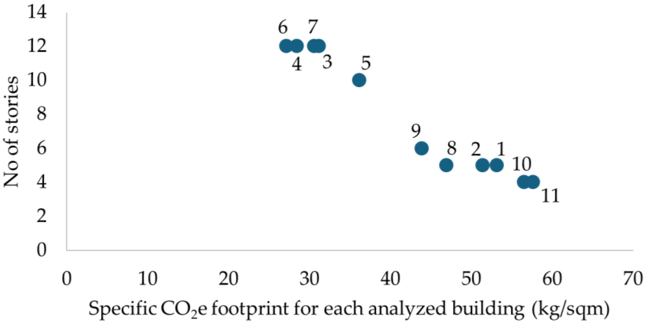
Table 14. Lower values are observed for buildings with a greater number of stories. This trend is explained by the fact that the CO
2e emissions associated with renovating the building envelope at the non-trafficable roof terrace and the floor above the basement are distributed over a larger gross floor area when calculating specific emissions for taller buildings. This trend is clearly illustrated in
Figure 3, where the determined specific emission values are plotted against the number of stories of the analyzed buildings.
4. Discussion
The evaluations carried out in this study indicate that the specific CO2e emissions generated by energy renovation range between 27 kg/m2 and 58 kg/m2. For buildings with 10–12 stories, the specific CO2e emissions vary between 27 kg/m2 and 36 kg/m2, whereas for lower buildings with 4–6 stories, they range from 44 kg/m2 to 58 kg/m2.
The calculated CO2e emissions associated with proactive seismic retrofitting range from 6 kg/m2 for two-story buildings located in low-seismicity zones to 45 kg/m2 for 11-story buildings in high-seismicity zones. In the case of reactive seismic retrofitting of buildings damaged by a major earthquake, the CO2e emissions required for structural rehabilitation alone range between 23 kg/m2 and 121 kg/m2, depending on the building height and the seismicity of the site.
For a weighted average design ground acceleration of 0.27 g, the average CO2e emissions for proactive retrofitting are 11 kg/m2 for two-story buildings and 23 kg/m2 for buildings with more than five stories. For reactive retrofitting, the specific CO2e emissions rise to 42 kg/m2 and 62 kg/m2 for the same building categories.
It is observed that proactive seismic retrofitting results in significantly lower CO2e emissions than reactive retrofitting. This trend is explained by the fact that, in proactive retrofitting, the existing structure can contribute more substantially to the lateral resistance of the retrofitted structure, as it is not yet seismically damaged, and because the target lateral resistance of the retrofitted structure relative to the requirement for new structures is lower.
For the average design acceleration value, reactive seismic retrofitting has an environmental impact comparable to that of energy renovation. However, this trend varies depending on the seismic zone. In areas with high seismicity, typically with design ground accelerations equal to or greater than 0.3 g, CO2e emissions associated with reactive retrofitting are substantially higher than those from energy renovation.
It should be noted that in current practice, while structural intervention solutions are dimensioned based on the seismicity of the site—leading to significantly different material consumptions—energy renovation solutions are more uniform, even under different climatic conditions, and are primarily determined by technical and legal constraints, as described earlier.
In the event of a strong earthquake, seismically vulnerable buildings that have not been retrofitted are expected to suffer significant damage. Most buildings will experience damage to non-structural components, including envelope elements such as non-structural walls, windows, and exterior doors. This is particularly relevant for Romania, which is exposed to intermediate-depth Vrancea seismic hazard. Such earthquakes generate large horizontal displacements at the tops of buildings, incompatible with the deformation capacity of non-structural components [
39].
Consequently, during a major earthquake, buildings that have undergone energy renovation but not seismic retrofitting will suffer damage to the rehabilitated envelope components. This can negate the benefits of energy renovation. Considering that 37–67% of the CO2e footprint associated with energy renovation is due to the installation of triple-glass PVC windows, their replacement in the event of damage leads to a substantial increase in CO2e emissions. Damage to masonry walls also necessitates repair and replacement, requiring the removal and reapplication of insulating materials and finishing layers.
Analysis of the data from this study indicates that, in seismic zones, integrated interventions combining energy renovation with proactive seismic retrofitting are recommended to minimize the CO2e footprint. CO2e emissions associated with proactive seismic retrofitting are relatively low compared to those from energy renovation. Proactive retrofitting ensures the durability of energy renovation measures after a major earthquake. In contrast, reactive seismic retrofitting has a high environmental impact, with CO2e emissions 3–4 times higher than those for proactive retrofitting.
The calculated CO2e emissions for both proactive and reactive seismic retrofitting, as well as for energy renovation, are significantly lower than those for constructing new buildings. Energy renovation generates CO2e emissions equal to 6–12% of those associated with constructing similar new buildings. For seismic retrofitting, emissions range from 2 to 12% for proactive retrofitting and 5–29% for reactive retrofitting.
It is evident that energy renovation combined with proactive seismic retrofitting represents the most advantageous solution in seismic zones in terms of reducing CO2e emissions associated with construction processes compared to replacing the buildings with new constructions.
5. Conclusions
Achieving climate neutrality targets for the residential building stock requires energy renovation of these buildings. In seismic zones, the benefits of energy renovation can be lost in the event of a major earthquake. The conclusions presented in this study refer to the analyzed buildings and are formulated with respect to the seismic protection requirements specific to Romania.
The purpose of this study is to provide an overview of the CO2e emissions associated with energy renovation and, separately, with seismic retrofitting of generic buildings representative of the existing building stock.
Proactive seismic retrofitting, carried out before structural damage occurs due to a major earthquake, has a smaller environmental footprint compared to reactive retrofitting and is therefore recommended from this perspective. The CO2e emissions associated with proactive seismic retrofitting are lower than those for energy renovation. Any CO2e savings achieved by avoiding preventive retrofitting prior to energy renovation are lost in the event of a major earthquake, as damage to the building—including both structural and non-structural components—will require reactive seismic retrofitting and repetition of energy renovation works.
Even in high-seismicity zones, replacing the existing building stock with new buildings that meet current energy and seismic performance requirements is not a viable alternative in terms of limiting CO2e emissions from construction. When independent strategies for energy renovation and seismic retrofitting are applied, the resulting CO2e emissions in the least favorable cases remain significantly lower than those associated with constructing new buildings. This proves that the rehabilitation of the existing building stock represents a sustainable alternative to full replacement of energy and seismically vulnerable buildings.
Preventive seismic retrofitting combined with energy renovation, implemented as integrated interventions, represents the most suitable approach for reducing CO2e emissions associated with building works for an individual building.
This study can be extended by scaling the data obtained for the analyzed generic buildings to the entire building stock, in order to determine the most optimal intervention strategies. This would allow informed design of national funding programs for energy renovation and seismic retrofitting. Various seismic events can be considered, along with multi-year intervention scenarios for energy renovation and seismic retrofitting, to determine the most effective strategy for reducing CO2e emissions across the building stock.
The results presented in this study are valid with respect to the analyzed data and the assumptions explicitly stated in the article; however, they are not necessarily applicable to a specific building or a particular renovation context. The findings may be integrated into building stock-level studies, but they do not provide sufficient accuracy for the detailed assessment of an individual renovation project.
The assessment carried out in this study does not address the CO2e footprint associated with building operation, either before or after the interventions. In fact, the presented values are intended to support the substantiation of life-cycle CO2e footprint assessments for existing buildings, particularly when seismic or energy retrofitting interventions are implemented. The authors intend to complement the results presented in this paper with future evaluations of CO2e emissions that also account for the operational phase of buildings.